IMPLEMENTATION OF GMSK MODULATION SCHEME WITH CHANNEL EQUALIZATION
|
|
|
- Gwen McKenzie
- 6 years ago
- Views:
Transcription
1 IMPLEMENTATION OF GMSK MODULATION SCHEME WITH CHANNEL EQUALIZATION
2 References MX589 GMSK MODEM Application Modem Techniques in Satellite Communication Practical GMSK Data Transmission GMSK MODEM Application A Real Time DSP GMSK Modem with all Digital Symbol Synchronization by Richard Paul Lambert MATLAB CODE: clear all; close all; %********************************* % Variable Definition %********************************* DRate = 1; % data rate or 1 bit in one second M = 18; % no. of sample per bit N = 36; % no. of bits for simulation [-18:18] BT = 0.5; % Bandwidth*Period (cannot change ) T = 1/DRate; % data period, i.e 1 bit in one second Ts = T/M; k=[-18:18]; % Chen's values. More than needed; % only introduces a little more delay %****************************************************************** ********************** % CONSTRUCTION OF GAUSSIAN FILTER FOLLOWED BY SHAPING OF DATA BITS USING GAUSSIAN FILTER % %****************************************************************** ********************** alpha = sqrt(log(2))/(2*pi*bt); % alpha calculated for the gaussian filter response
3 h = exp(-(k*ts).^2/(2*alpha^2*t^2))/(sqrt(2*pi)*alpha*t); % Gaussian Filter Response in time domain figure; plot(h,'*r') title('response of Gaussian Filter'); xlabel( 'Sample at Ts'); ylabel( 'Normalized Magnitude'); grid; bits = [zeros(1,36) 1 zeros(1,36) 1 zeros(1,36) -1 zeros(1,36) -1 zeros(1,36) 1 zeros(1,36) 1 zeros(1,36) 1 zeros(1,36)]; % here the data is randomly selected to be transmitted and, here 1 indicates 1 and -1 indicates % zero %************** % MODULATION % %************** m = filter(h,1,bits);% bits are passed through the all pole filter described by h, i.e bits are % shaped by gaussian filter t0=.35; % signal duration ts= ; % sampling interval fc=200; % carrier frequency kf=100; % Modulation index fs=1/ts; % sampling frequency t=[0:ts:t0]; % time vector df=0.25; % required frequency resolution int_m(1)=0; for i=1:length(t)-1 % Integral of m int_m(i+1)=int_m(i)+m(i)*ts; end tx_signal=cos(2*pi*fc*t+2*pi*kf*int_m); % Frequency Modulation (FM) is a form of angle modulation in which the instantaneous frequency % of the carrier signal is varied linearly with the baseband message signal m(t),
4 x = cos(2*pi*fc*t); y = sin(2*pi*fc*t); figure; subplot(2,1,1) stem(bits(1:250)) title('random DATA BITS,+1 FOR ONE AND -1 FOR ZERO '); grid; subplot(2,1,2) plot(m(1:250),'r') title('gaussian SHAPED TRAIN'); xlim([0 260]); figure; plot(tx_signal) title('modulated SIGNAL'); xlim([0 225]); % Channel Equalization % First, a channel simulator is designed to introduce effects common to wireless signals such as % Doppler shifts, Rayleigh fading, phase offsets, and multipath interference. These channel % conditions are used to test the performance of the system in a simulated mobile radio environment. % Second, AWGN is added in the signal. The variance of the Gaussian noise may be changed to test % the performance for different signal to noise ratios, while signal amplitude is held constant. % load 'C:\CASE\Digital_Communication\project\channel.mat' load 'channel.mat' h = channel; N1 = 700; x1 = randn(n1,1); d = filter(h,1,x1); Ord = 256; Lambda = 0.98; delta = 0.001;
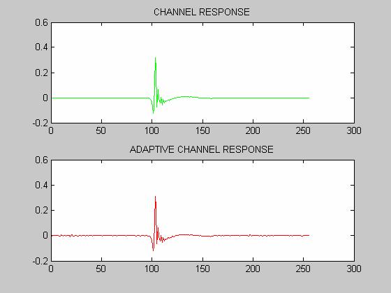
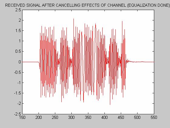
5 P = delta*eye(ord);% Create output pulse: rectangular pulse convolved with first-order % low-pass filter impulse response. w = zeros(ord,1); % adaptive equalization technique is used to cancel the effects of channel % induced effects, underneath is the code for the technique for n = Ord:N1 u = x1(n:-1:n-ord+1); pi = P*u; k = Lambda + u'*pi; K = pi/k; e(n) = d(n) - w'*u; w = w + K *e(n); PPrime = K*pi'; P = (P-PPrime)/Lambda; w_err(n) = norm(h-w); end figure; subplot(2,1,1); plot(h,'g'); title('channel RESPONSE'); subplot(2,1,2); plot(w,'r'); title('adaptive CHANNEL RESPONSE'); % now the channel effects are added to our transmitted signal rcvd_signal = conv(h,tx_signal); figure; plot(rcvd_signal); title('received SIGNAL, AFTER INDUCING CHANNEL EFFECTS'); axis([ ]) eq_signal = conv(1/w,rcvd_signal); figure; %subplot(3,1,1); plot(eq_signal,'r');
6 axis([ ]) title('received SIGNAL AFTER CANCELLING EFFECTS OF CHANNEL (EQUALIZATION DONE)'); figure; subplot(2,1,1); plot(eq_signal,'g'); title('received SIGNAL AFTER CANCELLING EFFECTS OF CHANNEL (AXIS CORRECTED)'); axis([ ]);% here the scale for the received signal is corrected subplot(2,1,2); plot(tx_signal,'r'); title('modulated SIGNAL'); %The following is the source code for a Matlab function that does one-bit diffren- %tial detection. This detection function also simulates synchronization using Gardner's %timing recovery algorithm for the case of over-sampling.it was creating %the problem thats why it has been left % num = 1; % time = 2*N+1; % T =N; % mu = 0.02; % error(1) = 0; % shift = 0; % timing_error =0; % totsteps = 0;.44 %B = fir1(32,0.18); % Demodulation eq_signal2 = eq_signal(215:460-1); eq_signal1 = eq_signal(200:460-1); EQ_SIG=awgn(eq_signal2,20); % here directly matlab function is made use of for the demodulation of the % received signal z_dir=demod(eq_sig,fc,fs,'fm',1);
7 %figure;plot(z_dir);title('signal OBTAINED FREQUENCY DEMODULATION)'); In = x.*eq_signal1; Qn = y.*eq_signal1; noisei = awgn(in,20); noiseq = awgn(qn,20); I = In + noisei; Q = Qn + noiseq; LP = fir1(32,0.18); yi = filter(lp,1,i); yq = filter(lp,1,q); figure; subplot(2,1,1); plot(yi); title('inphase COMPONENT'); xlim([0 256]); subplot(2,1,2); plot(yq,'r'); title('quadrature COMPONENT'); xlim([0 256]); Z = yi + yq*j; % OQPSK (Offset QPSK) is used to detect the signal. Giving an offset makes the phase shift of 90 % instead of 180. Therefore signal transition ( at every Tb sec) does not pass through a zero and % so no phase change occurs. demod(1:n) = imag(z(1:n)); demod(n+1:length(z)) = imag(z(n+1:length(z)).*conj(z(1:length(z)-n))); xt = -10*demod(1:N/2:length(demod)); xd = xt(4:2:length(xt)); figure; stem(xd)
8 title('demodulated SIGNAL USING OQPSK'); %m2 = conv(1/h,z_dir);figure;plot(m2)% here signal is convolved back with the inverse gaussian filter % to recover the bits figure; subplot(2,1,1);stem(z_dir,'r');title('recovered SIGNAL AFTER FREQUENCY DEMODULATION'); subplot(2,1,2);stem(bits(1:250));title('bits WHICH WERE TRANSMITTED'); %figure; %plot(demod); % while(time <=length(z)-t) % num = num+1; % samples(num) = (demod(time) >0)*2-1 % error(num) = (sign(demod(fix(time)))-sign(demod(fix(time- T))))*(demod(time-T/2)); % shift = error(num)*n*mu; % steps = fix(shift); % time = time + T-steps; % end Results:

9 figure 1 figure 2

10 figure 3 figure 4

11 figure 5 figure 6

12 fig 7 fig 8
13 fig 9 fig 10
14 IMPLEMENTATION OF GMSK RADIO MODULATION Gaussian Minimum Shift Keying (GMSK) is a digital modulation scheme commonly used in wireless, mobile communications. Advantages of using GMSK are its relatively narrow BW, constant envelope modulation, and its suitability for both coherent and non-coherent detection. GMSK is derived from MSK. MSK is a continuous phase modulation scheme where the modulated carrier contains no phase discontinuities and frequency changes occur at the carrier zero crossings. The fundamental problem with MSK is its side lobes extending well above the data rate as shown in the figure. To reduce the transmission BW required input data may be prefiltered prior to modulation using a specific form of low pass filtering. The pre-modulation low pass filter must have a narrow BW with a sharp cutoff frequency and very little offshoot in its impulse response which is characterized by a classical Gaussian distribution.
15 The amount of ISI introduced depends on the BW-time product, BT, of the Gaussian transmit filter. The premodulation Gaussian filtering introduces ISI in the transmitted signal, but it can be shown that the degradation is not severe if the 3 db-bandwidth-bit duration product (BT) of the filter is greater than 0.5. The GMSK premodulation filter has an impulse response given by h G 2 π π ( t) = exp t 2 α α 2 Where the value of alpha is calculated using the equation α = ln 2 2B = B The premodulation Gaussian filtering introduces ISI in the transmitted signal, but it can be shown that the degradation is not severe if the 3 db-bandwidth-bit duration product (BT) of the filter is greater than 0.5.
16 Gaussian Filtering: The GMSK modulation is done with the help of Gaussian shaped filter. The signal is made by convolving the bit sequence with the Gaussian Filter. The message signal is integrated to get the phase of it. Then this phase is modulated which results ultimately in a FM signal. The single output is the GMSK signal. Shaped Impulse Input "Gaussian" Gaussian Lowpass Filter Output
17 Frequency Modulation Frequency Modulation (FM) is a form of angle modulation in which the instantaneous frequency of the carrier signal is varied linearly with the baseband message signal m(t), t f s = A cos[ 2πfct + θ ( t)] = A cos[2πf t + 2πk m( η) dη] FM c c c Where kf is the frequency deviation constant (measured in units of Hz/V) The Channel: First, a channel simulator is designed to introduce effects common to wireless signals such as Doppler shifts, Rayleigh fading, phase offsets, and multipath interference. These channel conditions are used to test the performance of the system in a simulated mobile radio environment. Second, AWGN is added in the signal. The variance of the Gaussian noise may be changed to test the performance for different signal to noise ratios, while signal amplitude is held constant. Demodulation: is done by multiplying the signal with the carrier. After filtering out the carrier signal with a pair of low pass filters, only the baseband I and Q components remain.
18 Detection: OQPSK (Offset QPSK) is used to detect the signal. Giving an offset makes the phase shift of 90 instead of 180. Therefore signal transition ( at every Tb sec) does not pass through a zero and so no phase change occurs.
19 Channel Equalization Channel Equalization is to cancel the effect of the channel distortion. It removes Inter symbol interference and assist in the decision of detecting the bits. Several advanced techniques are used in the equalization of channel and most of the methods are adaptive e.g: Minimum Mean Square Method Least Square Method Recursive Least Square Least Mean Square Basic Idea
20 All the equalization filters are basically adaptive transversal filter, they are basically based on minimum mean square error i.e. J = E(e 2 ) This is basically cost function for over scenario and we have to minimize it with respect to our weights of transversal filter which are basically adapting with the help of error. J = E[(y d) 2 ] J = E[ue] And finally we get The desired Weinner Hopf equation W = R -1 r All the algorithms are basically are the version of this equation.
Revision of Wireless Channel
 Revision of Wireless Channel Quick recap system block diagram CODEC MODEM Wireless Channel Previous three lectures looked into wireless mobile channels To understand mobile communication technologies,
Wireless Communication Fading Modulation
 EC744 Wireless Communication Fall 2008 Mohamed Essam Khedr Department of Electronics and Communications Wireless Communication Fading Modulation Syllabus Tentatively Week 1 Week 2 Week 3 Week 4 Week 5
Chapter 6 Modulation Techniques for Mobile Radio
 Chapter 6. Modulation Techniques for Mobile Radio - 1-2 nd Semester, 2010 Chapter 6 Modulation Techniques for Mobile Radio Text. [1] T. S. Rappaport, Wireless Communications - Principles and Practice,
CALIFORNIA STATE UNIVERSITY, NORTHRIDGE FADING CHANNEL CHARACTERIZATION AND MODELING
 CALIFORNIA STATE UNIVERSITY, NORTHRIDGE FADING CHANNEL CHARACTERIZATION AND MODELING A graduate project submitted in partial fulfillment of the requirements For the degree of Master of Science in Electrical
MSK has three important properties. However, the PSD of the MSK only drops by 10log 10 9 = 9.54 db below its midband value at ft b = 0.
 Gaussian MSK MSK has three important properties Constant envelope (why?) Relatively narrow bandwidth Coherent detection performance equivalent to that of QPSK However, the PSD of the MSK only drops by
EENG473 Mobile Communications Module 3 : Week # (12) Mobile Radio Propagation: Small-Scale Path Loss
 Mobile Radio Propagation: Small-Scale Path Loss") EENG473 Mobile Communications Module 3 : Week # (12) Mobile Radio Propagation: Small-Scale Path Loss Introduction Small-scale fading is used to describe the rapid fluctuation of the amplitude of a radio
EENG473 Mobile Communications Module 3 : Week # (12) Mobile Radio Propagation: Small-Scale Path Loss Introduction Small-scale fading is used to describe the rapid fluctuation of the amplitude of a radio
21. Orthonormal Representation of Signals
 1. Orthonormal Representation of Signals Introduction An analogue communication system is designed for the transmission of information in analogue form. he source information is in analogue form. In practice,
ELT COMMUNICATION THEORY
 ELT 41307 COMMUNICATION THEORY Project work, Fall 2017 Experimenting an elementary single carrier M QAM based digital communication chain 1 ASSUMED SYSTEM MODEL AND PARAMETERS 1.1 SYSTEM MODEL In this
Wireless Communication: Concepts, Techniques, and Models. Hongwei Zhang
 Wireless Communication: Concepts, Techniques, and Models Hongwei Zhang http://www.cs.wayne.edu/~hzhang Outline Digital communication over radio channels Channel capacity MIMO: diversity and parallel channels
Communication Theory
 Communication Theory Adnan Aziz Abstract We review the basic elements of communications systems, our goal being to motivate our study of filter implementation in VLSI. Specifically, we review some basic
filter, followed by a second mixerdownconverter,
 G DECT Receiver for Frequency Selective Channels G. Ramesh Kumar K.Giridhar Telecommunications and Computer Networks (TeNeT) Group Department of Electrical Engineering Indian Institute of Technology, Madras
Communication Channels
 Communication Channels wires (PCB trace or conductor on IC) optical fiber (attenuation 4dB/km) broadcast TV (50 kw transmit) voice telephone line (under -9 dbm or 110 µw) walkie-talkie: 500 mw, 467 MHz
Degradation of BER by Group Delay in Digital Phase Modulation
 The Fourth Advanced International Conference on Telecommunications Degradation of BER by Group Delay in Digital Phase Modulation A.Azizzadeh 1, L.Mohammadi 1 1 Iran Telecommunication Research Center (ITRC)
Objectives. Presentation Outline. Digital Modulation Revision
 Digital Modulation Revision Professor Richard Harris Objectives To identify the key points from the lecture material presented in the Digital Modulation section of this paper. What is in the examination
Analog Communication.
 Analog Communication Vishnu N V Tele is Greek for at a distance, and Communicare is latin for to make common. Telecommunication is the process of long distance communications. Early telecommunications
Problems from the 3 rd edition
 (2.1-1) Find the energies of the signals: a) sin t, 0 t π b) sin t, 0 t π c) 2 sin t, 0 t π d) sin (t-2π), 2π t 4π Problems from the 3 rd edition Comment on the effect on energy of sign change, time shifting
DIGITAL COMMUNICATIONS SYSTEMS. MSc in Electronic Technologies and Communications
 DIGITAL COMMUNICATIONS SYSTEMS MSc in Electronic Technologies and Communications Bandpass binary signalling The common techniques of bandpass binary signalling are: - On-off keying (OOK), also known as
Wireless Channel Propagation Model Small-scale Fading
 Wireless Channel Propagation Model Small-scale Fading Basic Questions T x What will happen if the transmitter - changes transmit power? - changes frequency? - operates at higher speed? Transmit power,
WIRELESS COMMUNICATIONS PRELIMINARIES
 WIRELESS COMMUNICATIONS Preliminaries Radio Environment Modulation Performance PRELIMINARIES db s and dbm s Frequency/Time Relationship Bandwidth, Symbol Rate, and Bit Rate 1 DECIBELS Relative signal strengths
Amplitude Modulation, II
 Amplitude Modulation, II Single sideband modulation (SSB) Vestigial sideband modulation (VSB) VSB spectrum Modulator and demodulator NTSC TV signsals Quadrature modulation Spectral efficiency Modulator
Channel. Muhammad Ali Jinnah University, Islamabad Campus, Pakistan. Multi-Path Fading. Dr. Noor M Khan EE, MAJU
 Instructor: Prof. Dr. Noor M. Khan Department of Electronic Engineering, Muhammad Ali Jinnah University, Islamabad Campus, Islamabad, PAKISTAN Ph: +9 (51) 111-878787, Ext. 19 (Office), 186 (Lab) Fax: +9
Lecture 13. Introduction to OFDM
 Lecture 13 Introduction to OFDM Ref: About-OFDM.pdf Orthogonal frequency division multiplexing (OFDM) is well-known to be effective against multipath distortion. It is a multicarrier communication scheme,
Digital Modulation Schemes
 Digital Modulation Schemes 1. In binary data transmission DPSK is preferred to PSK because (a) a coherent carrier is not required to be generated at the receiver (b) for a given energy per bit, the probability
PERFORMANCE COMPARISON OF SOQPSK DETECTORS: COHERENT VS. NONCOHERENT
 PERFORMANCE COMPARISON OF SOQPSK DETECTORS: COHERENT VS. NONCOHERENT Tom Bruns L-3 Communications Nova Engineering, Cincinnati, OH ABSTRACT Shaped Offset Quadrature Shift Keying (SOQPSK) is a spectrally
Performance of Wideband Mobile Channel with Perfect Synchronism BPSK vs QPSK DS-CDMA
 Performance of Wideband Mobile Channel with Perfect Synchronism BPSK vs QPSK DS-CDMA By Hamed D. AlSharari College of Engineering, Aljouf University, Sakaka, Aljouf 2014, Kingdom of Saudi Arabia, hamed_100@hotmail.com
ECEn 665: Antennas and Propagation for Wireless Communications 131. s(t) = A c [1 + αm(t)] cos (ω c t) (9.27)
![ECEn 665: Antennas and Propagation for Wireless Communications 131. s(t) = A c [1 + αm(t)] cos (ω c t) (9.27)](/thumbs/88/116957690.jpg "ECEn 665: Antennas and Propagation for Wireless Communications 131. s(t) = A c [1 + αm(t)] cos (ω c t) (9.27)") ECEn 665: Antennas and Propagation for Wireless Communications 131 9. Modulation Modulation is a way to vary the amplitude and phase of a sinusoidal carrier waveform in order to transmit information. When
ECEn 665: Antennas and Propagation for Wireless Communications 131 9. Modulation Modulation is a way to vary the amplitude and phase of a sinusoidal carrier waveform in order to transmit information. When
Wireless Communication Systems Laboratory Lab#1: An introduction to basic digital baseband communication through MATLAB simulation Objective
 Wireless Communication Systems Laboratory Lab#1: An introduction to basic digital baseband communication through MATLAB simulation Objective The objective is to teach students a basic digital communication
Chapter 2 Channel Equalization
 Chapter 2 Channel Equalization 2.1 Introduction In wireless communication systems signal experiences distortion due to fading [17]. As signal propagates, it follows multiple paths between transmitter and
Multi-Path Fading Channel
 Instructor: Prof. Dr. Noor M. Khan Department of Electronic Engineering, Muhammad Ali Jinnah University, Islamabad Campus, Islamabad, PAKISTAN Ph: +9 (51) 111-878787, Ext. 19 (Office), 186 (Lab) Fax: +9
ECE 476/ECE 501C/CS Wireless Communication Systems Winter Lecture 6: Fading
 ECE 476/ECE 501C/CS 513 - Wireless Communication Systems Winter 2004 Lecture 6: Fading Last lecture: Large scale propagation properties of wireless systems - slowly varying properties that depend primarily
Wireless PHY: Modulation and Demodulation
 Wireless PHY: Modulation and Demodulation Y. Richard Yang 09/11/2012 Outline Admin and recap Amplitude demodulation Digital modulation 2 Admin Assignment 1 posted 3 Recap: Modulation Objective o Frequency
ECE 476/ECE 501C/CS Wireless Communication Systems Winter Lecture 6: Fading
 ECE 476/ECE 501C/CS 513 - Wireless Communication Systems Winter 2005 Lecture 6: Fading Last lecture: Large scale propagation properties of wireless systems - slowly varying properties that depend primarily
Master s Thesis Defense
 Master s Thesis Defense Comparison of Noncoherent Detectors for SOQPSK and GMSK in Phase Noise Channels Afzal Syed August 17, 2007 Committee Dr. Erik Perrins (Chair) Dr. Glenn Prescott Dr. Daniel Deavours
WIRELESS COMMUNICATION TECHNOLOGIES (16:332:546) LECTURE 5 SMALL SCALE FADING
 LECTURE 5 SMALL SCALE FADING") WIRELESS COMMUNICATION TECHNOLOGIES (16:332:546) LECTURE 5 SMALL SCALE FADING Instructor: Dr. Narayan Mandayam Slides: SabarishVivek Sarathy A QUICK RECAP Why is there poor signal reception in urban clutters?
WIRELESS COMMUNICATION TECHNOLOGIES (16:332:546) LECTURE 5 SMALL SCALE FADING Instructor: Dr. Narayan Mandayam Slides: SabarishVivek Sarathy A QUICK RECAP Why is there poor signal reception in urban clutters?
Muhammad Ali Jinnah University, Islamabad Campus, Pakistan. Fading Channel. Base Station
 Fading Lecturer: Assoc. Prof. Dr. Noor M Khan Department of Electronic Engineering, Muhammad Ali Jinnah University, Islamabad Campus, Islamabad, PAKISTAN Ph: +9 (51) 111-878787, Ext. 19 (Office), 186 (ARWiC
Objectives. Presentation Outline. Digital Modulation Lecture 03
 Digital Modulation Lecture 03 Inter-Symbol Interference Power Spectral Density Richard Harris Objectives To be able to discuss Inter-Symbol Interference (ISI), its causes and possible remedies. To be able
Lab 3.0. Pulse Shaping and Rayleigh Channel. Faculty of Information Engineering & Technology. The Communications Department
 Faculty of Information Engineering & Technology The Communications Department Course: Advanced Communication Lab [COMM 1005] Lab 3.0 Pulse Shaping and Rayleigh Channel 1 TABLE OF CONTENTS 2 Summary...
Fundamentals of Digital Communication
 Fundamentals of Digital Communication Network Infrastructures A.A. 2017/18 Digital communication system Analog Digital Input Signal Analog/ Digital Low Pass Filter Sampler Quantizer Source Encoder Channel
Mobile & Wireless Networking. Lecture 2: Wireless Transmission (2/2)
") 192620010 Mobile & Wireless Networking Lecture 2: Wireless Transmission (2/2) [Schiller, Section 2.6 & 2.7] [Reader Part 1: OFDM: An architecture for the fourth generation] Geert Heijenk Outline of Lecture
192620010 Mobile & Wireless Networking Lecture 2: Wireless Transmission (2/2) [Schiller, Section 2.6 & 2.7] [Reader Part 1: OFDM: An architecture for the fourth generation] Geert Heijenk Outline of Lecture
Project I: Phase Tracking and Baud Timing Correction Systems
 Project I: Phase Tracking and Baud Timing Correction Systems ECES 631, Prof. John MacLaren Walsh, Ph. D. 1 Purpose In this lab you will encounter the utility of the fundamental Fourier and z-transform
Microwave Seminar. Noise and Bit Error Ratio. J. Richie. Spring 2013
 Microwave Seminar Noise and Bit Error Ratio J. Richie Spring 2013 Outline Noise Noise and Equivalent Temperature Noise Figure Small Scale Fade and Multipath Impulse Response Model Types of Fading Modulation
Performance Evaluation of OFDM System with Rayleigh, Rician and AWGN Channels
 Performance Evaluation of OFDM System with Rayleigh, Rician and AWGN Channels Abstract A Orthogonal Frequency Division Multiplexing (OFDM) scheme offers high spectral efficiency and better resistance to
Subtractive Synthesis. Describing a Filter. Filters. CMPT 468: Subtractive Synthesis
 Subtractive Synthesis CMPT 468: Subtractive Synthesis Tamara Smyth, tamaras@cs.sfu.ca School of Computing Science, Simon Fraser University November, 23 Additive synthesis involves building the sound by
ECE 3500: Fundamentals of Signals and Systems (Fall 2014) Lab 4: Binary Phase-Shift Keying Modulation and Demodulation
 Lab 4: Binary Phase-Shift Keying Modulation and Demodulation") ECE 3500: Fundamentals of Signals and Systems (Fall 2014) Lab 4: Binary Phase-Shift Keying Modulation and Demodulation Files necessary to complete this assignment: none Deliverables Due: Before your assigned
ECE 3500: Fundamentals of Signals and Systems (Fall 2014) Lab 4: Binary Phase-Shift Keying Modulation and Demodulation Files necessary to complete this assignment: none Deliverables Due: Before your assigned
EE5713 : Advanced Digital Communications
 EE573 : Advanced Digital Communications Week 4, 5: Inter Symbol Interference (ISI) Nyquist Criteria for ISI Pulse Shaping and Raised-Cosine Filter Eye Pattern Error Performance Degradation (On Board) Demodulation
INTERFERENCE SELF CANCELLATION IN SC-FDMA SYSTEMS -A CAMPARATIVE STUDY
 INTERFERENCE SELF CANCELLATION IN SC-FDMA SYSTEMS -A CAMPARATIVE STUDY Ms Risona.v 1, Dr. Malini Suvarna 2 1 M.Tech Student, Department of Electronics and Communication Engineering, Mangalore Institute
Analysis of Interference & BER with Simulation Concept for MC-CDMA
 IOSR Journal of Electronics and Communication Engineering (IOSR-JECE) e-issn: 2278-2834,p- ISSN: 2278-8735.Volume 9, Issue 4, Ver. IV (Jul - Aug. 2014), PP 46-51 Analysis of Interference & BER with Simulation
CHAPTER 3 ADAPTIVE MODULATION TECHNIQUE WITH CFO CORRECTION FOR OFDM SYSTEMS
 44 CHAPTER 3 ADAPTIVE MODULATION TECHNIQUE WITH CFO CORRECTION FOR OFDM SYSTEMS 3.1 INTRODUCTION A unique feature of the OFDM communication scheme is that, due to the IFFT at the transmitter and the FFT
Mobile Communications
 Mobile Communications Wen-Shen Wuen Trans. Wireless Technology Laboratory National Chiao Tung University WS Wuen Mobile Communications 1 Outline Outline 1 Structure of Wireless Communication Link 2 Analog
The University of Texas at Austin Dept. of Electrical and Computer Engineering Final Exam
 The University of Texas at Austin Dept. of Electrical and Computer Engineering Final Exam Date: December 18, 2017 Course: EE 313 Evans Name: Last, First The exam is scheduled to last three hours. Open
SIGNALS AND SYSTEMS LABORATORY 13: Digital Communication
 SIGNALS AND SYSTEMS LABORATORY 13: Digital Communication INTRODUCTION Digital Communication refers to the transmission of binary, or digital, information over analog channels. In this laboratory you will
Modulation and Coding Tradeoffs
 0 Modulation and Coding Tradeoffs Contents 1 1. Design Goals 2. Error Probability Plane 3. Nyquist Minimum Bandwidth 4. Shannon Hartley Capacity Theorem 5. Bandwidth Efficiency Plane 6. Modulation and
ECE 476/ECE 501C/CS Wireless Communication Systems Winter Lecture 6: Fading
 ECE 476/ECE 501C/CS 513 - Wireless Communication Systems Winter 2003 Lecture 6: Fading Last lecture: Large scale propagation properties of wireless systems - slowly varying properties that depend primarily
Modern Quadrature Amplitude Modulation Principles and Applications for Fixed and Wireless Channels
 1 Modern Quadrature Amplitude Modulation Principles and Applications for Fixed and Wireless Channels W.T. Webb, L.Hanzo Contents PART I: Background to QAM 1 Introduction and Background 1 1.1 Modulation
UNIT TEST I Digital Communication
 Time: 1 Hour Class: T.E. I & II Max. Marks: 30 Q.1) (a) A compact disc (CD) records audio signals digitally by using PCM. Assume the audio signal B.W. to be 15 khz. (I) Find Nyquist rate. (II) If the Nyquist
PULSE DRIVEN GAUSSIAN MINIMUM SHIFT KEYING*
 0-7803-4902-498$1000 (c) 1998 EEE PULSE DRVEN GAUSSAN MNMUM SHFT KEYNG* Russell l% Rhodes Kenneth J Hetling Massachusetts nstitute Of Technology Lincoln Laboratory 244 wood St Lexington, MA 02173 Abstract
UTA EE5362 PhD Diagnosis Exam (Spring 2012) Communications
 Communications") EE536 Spring 013 PhD Diagnosis Exam ID: UTA EE536 PhD Diagnosis Exam (Spring 01) Communications Instructions: Verify that your exam contains 11 pages (including the cover sheet). Some space is provided
EE536 Spring 013 PhD Diagnosis Exam ID: UTA EE536 PhD Diagnosis Exam (Spring 01) Communications Instructions: Verify that your exam contains 11 pages (including the cover sheet). Some space is provided
PEAK TO AVERAGE POWER RATIO REDUCTION USING BANDWIDTH EFFICIENCY INCREASING METHOD IN OFDM SYSTEM
 www.arpapress.com/volumes/vol6issue/ijrras_6.pdf PEAK TO AVERAGE POWER RATIO REDUCTIO USIG BADWIDTH EFFICIECY ICREASIG METHOD I OFDM SYSTEM A.A. Abdul Wahab and M. F. Ain School of Electrical and Electronic
Performance Analysis of ICI in OFDM systems using Self-Cancellation and Extended Kalman Filtering
 Performance Analysis of ICI in OFDM systems using Self-Cancellation and Extended Kalman Filtering C.Satya Haritha, K.Prasad Abstract - Orthogonal Frequency Division Multiplexing (OFDM) is a multicarrier
DT Filters 2/19. Atousa Hajshirmohammadi, SFU
 1/19 ENSC380 Lecture 23 Objectives: Signals and Systems Fourier Analysis: Discrete Time Filters Analog Communication Systems Double Sideband, Sub-pressed Carrier Modulation (DSBSC) Amplitude Modulation
Digital Signal Processing Fourier Analysis of Continuous-Time Signals with the Discrete Fourier Transform
 Digital Signal Processing Fourier Analysis of Continuous-Time Signals with the Discrete Fourier Transform D. Richard Brown III D. Richard Brown III 1 / 11 Fourier Analysis of CT Signals with the DFT Scenario:
CHAPTER 5. Additional Problems (a) The AM signal is defined by st () = A c. k a A c 1
 The AM signal is defined by st () = A c. k a A c 1") CHAPTER 5 Additional Problems 5.7 (a) The AM signal is defined by st () A c ( + k a mt ()) cos( ω c k a A c + ------------ + t cos( ω c To obtain 5% modulation, we choose k a, which results in the modulated
CHAPTER 5 Additional Problems 5.7 (a) The AM signal is defined by st () A c ( + k a mt ()) cos( ω c k a A c + ------------ + t cos( ω c To obtain 5% modulation, we choose k a, which results in the modulated
Performance Analysis of Ofdm Transceiver using Gmsk Modulation Technique
 Performance Analysis of Ofdm Transceiver using Gmsk Modulation Technique Gunjan Negi Student, ECE Department GRD Institute of Management and Technology Dehradun, India negigunjan10@gmail.com Anuj Saxena
Physical Layer: Modulation, FEC. Wireless Networks: Guevara Noubir. S2001, COM3525 Wireless Networks Lecture 3, 1
 Wireless Networks: Physical Layer: Modulation, FEC Guevara Noubir Noubir@ccsneuedu S, COM355 Wireless Networks Lecture 3, Lecture focus Modulation techniques Bit Error Rate Reducing the BER Forward Error
Lecture 9: Spread Spectrum Modulation Techniques
 Lecture 9: Spread Spectrum Modulation Techniques Spread spectrum (SS) modulation techniques employ a transmission bandwidth which is several orders of magnitude greater than the minimum required bandwidth
Mobile Radio Propagation Channel Models
 Wireless Information Transmission System Lab. Mobile Radio Propagation Channel Models Institute of Communications Engineering National Sun Yat-sen University Table of Contents Introduction Propagation
Chapter 2: Wireless Transmission. Mobile Communications. Spread spectrum. Multiplexing. Modulation. Frequencies. Antenna. Signals
 Mobile Communications Chapter 2: Wireless Transmission Frequencies Multiplexing Signals Spread spectrum Antenna Modulation Signal propagation Cellular systems Prof. Dr.-Ing. Jochen Schiller, http://www.jochenschiller.de/
Project 2 - Speech Detection with FIR Filters
 Project 2 - Speech Detection with FIR Filters ECE505, Fall 2015 EECS, University of Tennessee (Due 10/30) 1 Objective The project introduces a practical application where sinusoidal signals are used to
EE4512 Analog and Digital Communications Chapter 6. Chapter 6 Analog Modulation and Demodulation
 Chapter 6 Analog Modulation and Demodulation Chapter 6 Analog Modulation and Demodulation Amplitude Modulation Pages 306-309 309 The analytical signal for double sideband, large carrier amplitude modulation
Multi-carrier Modulation and OFDM
 3/28/2 Multi-carrier Modulation and OFDM Prof. Luiz DaSilva dasilval@tcd.ie +353 896-366 Multi-carrier systems: basic idea Typical mobile radio channel is a fading channel that is flat or frequency selective
Wireless communication system based on GMSK modulation scheme
 ATTI DELLA FONDAZIONE GIORGIO RONCHI ANNO LXVI, 2011 - N. 2 COMMUNICATIONS Wireless communication system based on GMSK modulation scheme SATTAR B. SADKHAN (*), NIDAA A. ABBAS (*), M. HUTAHIT (**) SUMMARY.
UTILIZATION OF AN IEEE 1588 TIMING REFERENCE SOURCE IN THE inet RF TRANSCEIVER
 UTILIZATION OF AN IEEE 1588 TIMING REFERENCE SOURCE IN THE inet RF TRANSCEIVER Dr. Cheng Lu, Chief Communications System Engineer John Roach, Vice President, Network Products Division Dr. George Sasvari,
Self-interference Handling in OFDM Based Wireless Communication Systems
 Self-interference Handling in OFDM Based Wireless Communication Systems Tevfik Yücek yucek@eng.usf.edu University of South Florida Department of Electrical Engineering Tampa, FL, USA (813) 974 759 Tevfik
Performance analysis of BPSK system with ZF & MMSE equalization
 Performance analysis of BPSK system with ZF & MMSE equalization Manish Kumar Department of Electronics and Communication Engineering Swift institute of Engineering & Technology, Rajpura, Punjab, India
Symbol Synchronization Techniques in Digital Communications
 Rochester Institute of Technology RIT Scholar Works Theses Thesis/Dissertation Collections 5-12-2017 Symbol Synchronization Techniques in Digital Communications Mohammed Al-Hamiri mga5528@rit.edu Follow
EXPERIMENT WISE VIVA QUESTIONS
 EXPERIMENT WISE VIVA QUESTIONS Pulse Code Modulation: 1. Draw the block diagram of basic digital communication system. How it is different from analog communication system. 2. What are the advantages of
Mobile Radio Propagation: Small-Scale Fading and Multi-path
 Mobile Radio Propagation: Small-Scale Fading and Multi-path 1 EE/TE 4365, UT Dallas 2 Small-scale Fading Small-scale fading, or simply fading describes the rapid fluctuation of the amplitude of a radio
ANALOGUE TRANSMISSION OVER FADING CHANNELS
 J.P. Linnartz EECS 290i handouts Spring 1993 ANALOGUE TRANSMISSION OVER FADING CHANNELS Amplitude modulation Various methods exist to transmit a baseband message m(t) using an RF carrier signal c(t) =
CHAPTER 3 Noise in Amplitude Modulation Systems
 CHAPTER 3 Noise in Amplitude Modulation Systems NOISE Review: Types of Noise External (Atmospheric(sky),Solar(Cosmic),Hotspot) Internal(Shot, Thermal) Parameters of Noise o Signal to Noise ratio o Noise
Objectives. Presentation Outline. Digital Modulation Lecture 01
 Digital Modulation Lecture 01 Review of Analogue Modulation Introduction to Digital Modulation Techniques Richard Harris Objectives You will be able to: Classify the various approaches to Analogue Modulation
Fund. of Digital Communications Ch. 3: Digital Modulation
 Fund. of Digital Communications Ch. 3: Digital Modulation Klaus Witrisal witrisal@tugraz.at Signal Processing and Speech Communication Laboratory www.spsc.tugraz.at Graz University of Technology November
Digital Modulation Lecture 01. Review of Analogue Modulation Introduction to Digital Modulation Techniques Richard Harris
 Digital Modulation Lecture 01 Review of Analogue Modulation Introduction to Digital Modulation Techniques Richard Harris Objectives You will be able to: Classify the various approaches to Analogue Modulation
QUESTION BANK SUBJECT: DIGITAL COMMUNICATION (15EC61)
") QUESTION BANK SUBJECT: DIGITAL COMMUNICATION (15EC61) Module 1 1. Explain Digital communication system with a neat block diagram. 2. What are the differences between digital and analog communication systems?
QUESTION BANK SUBJECT: DIGITAL COMMUNICATION (15EC61) Module 1 1. Explain Digital communication system with a neat block diagram. 2. What are the differences between digital and analog communication systems?
Lecture 3: Wireless Physical Layer: Modulation Techniques. Mythili Vutukuru CS 653 Spring 2014 Jan 13, Monday
 Lecture 3: Wireless Physical Layer: Modulation Techniques Mythili Vutukuru CS 653 Spring 2014 Jan 13, Monday Modulation We saw a simple example of amplitude modulation in the last lecture Modulation how
EC6501 Digital Communication
 EC6501 Digital Communication UNIT -1 DIGITAL COMMUNICATION SYSTEMS Digital Communication system 1) Write the advantages and disadvantages of digital communication. [A/M 11] The advantages of digital communication
Class 4 ((Communication and Computer Networks))
)") Class 4 ((Communication and Computer Networks)) Lesson 5... SIGNAL ENCODING TECHNIQUES Abstract Both analog and digital information can be encoded as either analog or digital signals. The particular encoding
Class 4 ((Communication and Computer Networks)) Lesson 5... SIGNAL ENCODING TECHNIQUES Abstract Both analog and digital information can be encoded as either analog or digital signals. The particular encoding
IEEE pc-00/11. IEEE Broadband Wireless Access Working Group <http://ieee802.org/16>
 Project Title Date Submitted IEEE 802.16 Broadband Wireless Access Working Group A Brief Examination of CQPSK for CPE PHY Modulation 2000-02-17 Source Eric Jacobsen Intel 5000 W.
Chapter 4. Part 2(a) Digital Modulation Techniques
 Digital Modulation Techniques") Chapter 4 Part 2(a) Digital Modulation Techniques Overview Digital Modulation techniques Bandpass data transmission Amplitude Shift Keying (ASK) Phase Shift Keying (PSK) Frequency Shift Keying (FSK) Quadrature
Chapter 4 Part 2(a) Digital Modulation Techniques Overview Digital Modulation techniques Bandpass data transmission Amplitude Shift Keying (ASK) Phase Shift Keying (PSK) Frequency Shift Keying (FSK) Quadrature
Evaluation of channel estimation combined with ICI self-cancellation scheme in doubly selective fading channel
 ISSN (Online): 2409-4285 www.ijcsse.org Page: 1-7 Evaluation of channel estimation combined with ICI self-cancellation scheme in doubly selective fading channel Lien Pham Hong 1, Quang Nguyen Duc 2, Dung
 Modulations Analog Modulations Amplitude modulation (AM) Linear modulation Frequency modulation (FM) Phase modulation (PM) cos Angle modulation FM PM Digital Modulations ASK FSK PSK MSK MFSK QAM PAM Etc.
With a lot of material from Rich Nicholls, CTL/RCL and Kurt Sundstrom, of unknown whereabouts
 Signal Processing for OFDM Communication Systems Eric Jacobsen Minister of Algorithms, Intel Labs Communication Technology Laboratory/ Radio Communications Laboratory July 29, 2004 With a lot of material
COSC 3213: Computer Networks I: Chapter 3 Handout #4. Instructor: Dr. Marvin Mandelbaum Department of Computer Science York University Section A
 COSC 3213: Computer Networks I: Chapter 3 Handout #4 Instructor: Dr. Marvin Mandelbaum Department of Computer Science York University Section A Topics: 1. Line Coding: Unipolar, Polar,and Inverted ; Bipolar;
HW 6 Due: November 3, 10:39 AM (in class)
") ECS 332: Principles of Communications 2015/1 HW 6 Due: November 3, 10:39 AM (in class) Lecturer: Prapun Suksompong, Ph.D. Instructions (a) ONE part of a question will be graded (5 pt). Of course, you do
ECS 332: Principles of Communications 2015/1 HW 6 Due: November 3, 10:39 AM (in class) Lecturer: Prapun Suksompong, Ph.D. Instructions (a) ONE part of a question will be graded (5 pt). Of course, you do
Module 4. Signal Representation and Baseband Processing. Version 2 ECE IIT, Kharagpur
 Module 4 Signal Representation and Baseband Processing Lesson 1 Nyquist Filtering and Inter Symbol Interference After reading this lesson, you will learn about: Power spectrum of a random binary sequence;
The figures and the logic used for the MATLAB are given below.
 MATLAB FIGURES & PROGRAM LOGIC: Transmitter: The figures and the logic used for the MATLAB are given below. Binary Data Sequence: For our project we assume that we have the digital binary data stream.
Spread Spectrum (SS) is a means of transmission in which the signal occupies a
 is a means of transmission in which the signal occupies a") SPREAD-SPECTRUM SPECTRUM TECHNIQUES: A BRIEF OVERVIEW SS: AN OVERVIEW Spread Spectrum (SS) is a means of transmission in which the signal occupies a bandwidth in excess of the minimum necessary to send
SPREAD-SPECTRUM SPECTRUM TECHNIQUES: A BRIEF OVERVIEW SS: AN OVERVIEW Spread Spectrum (SS) is a means of transmission in which the signal occupies a bandwidth in excess of the minimum necessary to send
Implementation of Digital Signal Processing: Some Background on GFSK Modulation
 Implementation of Digital Signal Processing: Some Background on GFSK Modulation Sabih H. Gerez University of Twente, Department of Electrical Engineering s.h.gerez@utwente.nl Version 5 (March 9, 2016)
Frequency-Domain Channel Estimation for Single- Carrier Transmission in Fast Fading Channels
 Wireless Signal Processing & Networking Workshop Advanced Wireless Technologies II @Tohoku University 18 February, 2013 Frequency-Domain Channel Estimation for Single- Carrier Transmission in Fast Fading
A Faded-Compensation Technique for Digital Land Mobile Satellite Systems
 Title A Faded-Compensation Technique for Digital Land Mobile Satellite Systems Author(s) Lau, HK; Cheung, SW Citation International Journal of Satellite Communications and Networking, 1996, v. 14 n. 4,
Title: Pulse Amplitude Modulation.
 Title: Pulse Amplitude Modulation. AIM Write a program to take input Frequency of Message Signal and find out the Aliased and Anti-Aliased wave, and also the Carrier Signal, Message Signal and their Fourier