Binaural Hearing- Human Ability of Sound Source Localization
|
|
|
- Jessie Stewart
- 6 years ago
- Views:
Transcription

1 MEE09:07 Binaural Hearing- Human Ability of Sound Source Localization Parvaneh Parhizkari Master of Science in Electrical Engineering Blekinge Institute of Technology December 2008 Blekinge Institute of Technology School of Engineering Department of Signal Processing Supervisors: Dr. Nedelko Grbic Erik Loxbo Examiner: Dr. Nedelko Grbic Blekinge Tekniska Högskola SE Karlskrona Tel.vx Fax
2
3 Abstract The purpose of this project is to desig a systematical method in order to measure human directionality ability in horizontal plane with a single sound source. A completely virtual auditory model has been created in Matlab. The project consists of modeling binaural cues, designing digital filters, designing a test workbench, measuring listener's directionality and analyzing the data. The head related transfer function (HRTF) is computed by calculating the two most important binaural cues, interaural level difference (ILD) and interaural time difference (ITD). The platform is made in Matlab and all results have been shown by plots produced from Matlab code. The directionality test has been done with real human subjects and the results have been analyzed and presented. I
4 II
5 Table of Contents Page Abbreviation 1 Introduction 3 Background 5 1. Binaural Perception Binaural cues Interaural Time Differences Interaural Level Differences Head Related Transfer Function Minimum Audible angle Cone of Confusion The Spherical head model Modeling ITD Modeling ILD ILD Approximation in Spherical Head Model The HRTF in SHM The Virtual Auditory Model Calculating ITD Time Delay Filtering The FD-MF all pass filter Calculating ILD The Generated HRTF 32 III
6 4. The Directionality Test Work Bench and Test Equipments 4.1 The GUI Interface Test Requirements The ASIO Sound Card The Matlab Audio Processing Framework The Calibration The Test Environment The Directionality Test and The Error Calculation The Measurement Method The Test Procedure The Test Signals The Subjects The Experiment Average Directionality Error The Audiogram Data Analysis Improvement 50 -Conclusion 51 - Future Work 51 -Appendix A 53 -References 55 IV
7 Abbreviations ASIO: Audio Stream Input/ Output FD: Fractional Delay GUI: Graphic User Interface HRIR: Head Related Impulse Response HRTF: Head Related Transfer Function IID: Interaural Intensity Differences ILD: Interaural Level Differences IPD: Interaural Phase Differences ITD: Interaural Time Differences MAA: Minimum Audible Angle MF: Maximally Flat SHM: Spherical Head Model 1
8 2
9 Introduction Binaural hearing is human and other animal's ability to judge direction of a sound source. As long as man has lived on Earth he/she has been able to localize the sound source(s) by using two ears. Wide research has been done on binaural hearing in many advanced laboratories during last century. Many of them have worked with dummy heads and some of them have worked with humans. This thesis has focused on some of the recent researches and uses one of the existing models to determine a method for measuring human s directionality. The thesis scope is the horizontal plane and the binaural cues (ITD and ILD) have been simulated in azimuth. The "spherical head model" is one of the oldest and the easiest but the most powerful model that has been considered for creating the virtual auditory model. This thesis does not discuss about physiology of hearing and hearing organ. The investigated area is just between a sound source and entrance of pinna. 3
10 The assumptions are using a single sound source, working on horizontal plane in the front semicircle. We also suppose that 0 is at right ear, 180 is at left ear and 90 is in front of the head. The details of the work are discussed in following sections. In the background section there are some turnovers on recent researches. Binaural perception, binaural cues, head related transfer functions (HRTF) have been discussed in chapter 1. In chapter 2 the Spherical head model is been explained. The virtual auditory model and digital filter design and some calculations, have been put in section 3. The test workbench and the test equipment are presented in chapter 4 and chapter 5 consists of the binaural measurement and analysis of the results. 4
11 Background Lord Rayleigh (John William Strutt) found the localization process during He noted that if a sound source is in ipsilateral ear, then the head makes a shadow cast in contralateral ear. Therefore, the signal in the contralateral ear is been more attenuated than the ipsilateral one. He also noted that different parameters affect on localization at low and high frequencies. His theory was named "Duplex theory" and it is valid to now, of course with some extensions. Many models of binaural processing were created over the last century. "Spherical head model" (Lord Rayleigh, 1907 and Woodworth/Schlosberg, 1954), direct Cross-correlation of the stimuli model (Sayers and Cherry, 1957), The binaural crosscorrelation model (Jeffress, 1956), direct comparison of the amount of the left-sided and right-sided internal response to stimuli model (Bergeijk, 1962), interaural comparison auditory nerve activity model( Colburn, 1973, 1977) and many other models were created [12]. Many other researchers studied other aspects of the binaural hearing such as multi channel sound sources, moving sound sources, noise reduction and so on. Spherical Head Model (SHM) that will be presented in this project is the first binaural model and it was born in the first of the last century. Rayleigh's SHM (1907) was so simple. Woodworth 5
12 and Schlosberg (1954) calculated binaural cues in polar coordinate system [5]. Joel David Miller (2001) modeled the spherical head in Cartesian coordinate system [10]. 6
13 1. Binaural Perception 1.1 Binaural cues There are two important binaural physical cues in the horizontal plane. These two cues are: 1. Interaural time differences (delays), ITD and 2. Interaural level (intensity) differences, ILD or IID Interaural Time Differences The difference in arrival times from a sound source in ipsilateral and contralateral ear is called ITD. ITD happens because sound waves arrive to one ear earlier than another one. ITD is the dominant cue at frequencies lower than 1500 Hz. The wavelengths of frequencies lower than about 1.5 KHz are comparable with the human head size. The minimum ITD is zero and the maximum perceptible ITD is about µs. Figure 1.1 shows a simple single source spherical head model with head radius a and azimuth θ. In Rayleigh's spherical head model with a sound source at infinity, ITD has a simple explanation. He obtained the following formula for ITD: 7
14 Median Plane Horizontal plane Ipsilateral Ear θ θ θ a a lateralcontara Ear Figure 1.1- Rayleigh's spherical head model in horizontal plane a ITD ( sin) / 2 / 2 c (1) Here c is speed of sound (approximately 343 m/s) and θ is the angle between the line which has connected the sound source to the head center and the median plane in radian. With this formula the ITD is zero when the sound source is in front of the head and is 2.57a/ c, when the sound source is located at one of two ears at the sides. ITD is more sensitive in near-field (less than 1 meter source distance) than far-field. It is seen in the formula that ITD is frequency independent, but in some other binaural models it is dependent on frequency. The position of a sound source at distance dis shown in Figure 1.2. from the center of the head in a SHM has been 8
15 dis θ Ipsilateral Ear a Contaralateral Ear Vertical plane Figure 1.2- A sound source at distance dis from the center of the head in spherical head model in horizontal plane Interaural Level Differences The difference in sound pressure levels or intensities in ipsilateral and contralateral ear is called ILD or IID respectively. ILD is a dominant cue at frequencies higher than about 1500 Hz but generally affects the contralateral signals of all frequencies. ILD happens because the head makes a shadow cast in contralateral ear. The ILD dependency to frequency is illustrated in Figure 1.3. ILD is nonlinear with frequency and is strongly dependent on frequency over audible spectrum because sound waves are scattered when the head diameter is larger than the wavelengths and diffraction increases rapidly with increasing frequency. 9
16 250 Hz Head Shadow 6 KHz Figure 1.3- The head-shadow effect at high frequencies and ILD dependency to frequency and position The smallest detectable ILD is about 0.5 db, regardless of frequency. The far-field ILD doesn't exceed 5-6 db whereas the near-field ILD, for example, at 500 Hz exceeds 15 db [2]. 1.2 Head Related Transfer Function The transformation of a sound signal from a sound source to a listener's ears is called Head Related Transfer Function (HRTF) or Anatomical Transfer Function (ATF). HRTF is a function that characterizes and captures the binaural cues for sound localization. HRTF is an individual function for every person and every sound source location. It depends on frequency and azimuth 10
17 in 2 dimensional space. Using non-individual HRTF has a high measuring error and it is not as accurate as the individual type. In another phrase HRTF describes the filtering of a sound source before being received by the ears. Far-field HRTF is attenuated inversely by the range whereas in near-field, the HRTF follows the ILD changes. X() H L () H R () X L () X R () Figure 1.4-The HRTF for left and right ear As shown in Figure 1.4 the signals that are received by two ears are: X L() H L(). X( ) XR() H R(). X() 11
18 HL() and H R() are the frequency responses of the transformations for left and right ears respectively. HRTF is a frequency domain expression of the head related impulse response (HRIR). By knowing the HRTF is always possible to create binaural signals from monaural sound sources. HRTF is usually measured in far-field. HRTF in free field is a very complicate function whereas it is a simpler function in a virtual auditory model. May1994) Figure 1.5- Head related impulse response of KEMAR dummy head (The MIT Media Lab, Some HRTF measurements with dummy heads have been done in laboratories such as "The CIPIC Interface Laboratory" and "The MIT Media Lab" [17]. By putting the sound source(s) in different 12
19 places in the laboratories and recording the results using microphones, a series HRIRs have been obtained. In this project and with SHM, the HRTF is neither completely individual nor non-individual. The simulated HRTF should be regarded as an average type. It means the people who have the same head radii use the same HRTF for synthesis of binaural signals. It can be called "Average HRTF". 1.3 Minimum Audible angle In 1958, Mills obtained the MAA (Minimum Audible angle) as a function of frequency and azimuth. 1.3 Binaural Models Figure 1.3- Set of points with the same ITDsnd ILDs Figure 1.6-The minimum audible angle versus frequency, Mills (1958) 13
20 As shown in Figure 1.6 the MAA, by using headphones, is about 1 degree when the sound source is in front of head at frequency range about Hz. 1 degree MAA is proportional to smallest detectable ITD, about 10 µs. With increasing frequency the MMA increases. MAA is symmetric around model. 90 in the spherical head 1.4 Cone of Confusion Figure 1.7-Cone of confusion of azimuth The cone of confusion consists of the points that have identical ITDs and ILDs in 3D hearing space. Using only one of the cues for synthesis binaural signals in virtual auditory models causes the confusion. It doesn't usually happen in the nature because there are many other parameters for localizing the sound source(s) such as reflected sound waves from the environment and vision hearing. 14
21 2. The Spherical head model In the spherical head model (SHM) it is supposed that the head is as a sphere. All calculations of binaural cues are done under this assumption. The scattered audio signals by the head, torso, shoulders, outer ear and ear drum are ignored in binaural measurement with headphones. The SHM captures sound wave diffraction caused by the head and is a useful model for synthesizing binaural cues, ITD and ILD. The behavior of the ILD and ITD in SHM will be developed in this chapter. 2.1 Modeling ITD Figure 2.1 shows a spherical head model in horizontal plane. If the sound source is located in x, ) in Cartesian coordinates, ( ss yss the ITD has been solved by the following equations [10]: 15
22 Figure 2.1-The Spherical Head Model in horizontal plane (Joel D. Miller, 2001) L D 2 HR cos 1 ( HR/ D) AL AR L R AL AR AZ AZ 2 DLA HR* * /180 L DRA HR* * / AZ x y ss ss D.sin( ) R D.cos( ) 16
23 DLD ( x ss HR) 2 y 2 ss DRD ( x ss HR) 2 y 2 ss If the sound source is at right side Otherwise If the sound source is at left side Otherwise DL L DLA DL DLD DR L DRA DR DRD ITD abs ( DL DR ) / c (2) Woodworth and Schlosberg (1954) calculated the ITD in polar coordinate system and Joel D. Miller (2001) has solved the ITD equations in Cartesian system [10]. From (2), the ITD is a symmetrical function at the two sides, ipsilateral and contralateral. In the SHM, the ITD is strongly dependent on head radius and weakly dependent on source distance at far-field, but is frequency independent. If the absolute value of the ITD is calculated, it will be a symmetrical function at the two sides, ipsilateral and contralateral. 17
24 Figure 2.2 shows the dependency of ITD on the head radius in SHM. The source distance is 2m and the azimuth varies between 0 and 180 degrees. Changing 1 cm in the head radius causes 80 µs in the ITD in 0 or 180 degree (two sides in front of the ears). Figure 2.3 also shows the dependency of ITD to the source distance shows the dependency of ITD to the in SHM. The head radius is 9 cm. As shown in these two Figure ures the ITD is more sensitive to hr and does not change so much with the source distance. Dependency of the ITD to source distance can be described in another phrase. Figure 2.4 shows dependency of the ITD to source distance with constant azimuth angles hr=.09 m hr=.08 m hr=.1 m 500 ITD(us) Azimuth angle(degree) Figure 2.2-The ITD (µs) versus azimuth (degree) with distance source=2m and different head radii 18
25 dis= 5m dis= 2m dis= 1m 500 ITD(us) Azimuth angle Figure 2.3-The ITD (µs) versus azimuth (degree) with head radius= 9 cm and different source distances az= az=75 ITD(us) az=60 az= az= Source distance(m) Figure 2.4-The ITD (µs) versus the sound source distance (m) with different azimuth angles 19

26 2.2 Modeling ILD Figure 2.5 shows the frequency response of Rayleigh's spherical head model. It is seen in the figure that the most attenuation happens at the angles rises again at and the response That is a simple model and can fulfill ILD requirement. For the head size 9 cm, the normalized frequency μ=1 corresponds to a frequency about 607 Hz and μ=20 corresponds to frequency= Hz. The model behaves as a low pass filter for 100. Figure 2.5-The frequency response of the Rayleigh head model, μ= normalized frequency, a=head radius, c=speed of sound and f =frequency, θ=azimuth. The right ear is at θ= 0, and the left ear is at θ= 180 and θ= 90 is front of the head. 20
27 2.2.1 ILD Approximation in Spherical Head Model It is possible to model the ILD with a first order transfer function. A simple linear filter can provide a frequency response as given in Figure 2.5. It is needed to have a transfer function which changes with azimuth and frequency. One suggested transfer function is a single-pole, single-zero head shadow filter [1]: H (, ) 1 1 j 2 j 2 0 ( ) 2 (3) c. The normalized frequency corresponding to is a a 1. The coefficient is a function of θ and follows c this formula: ( ) 1 cos( ) or min ( ) (1 min ) (1 )cos( 180 ) 2 min (4) In the second row values 0. min 1 and min 150 give a good approximation of Figure 2.5 [1]. The model created from (3) and (4) is shown in Figure 2.6. In this model the response drops off with the angle 180. The case 21
28 0 is corresponding to maximum head shadow, and 2 creates 6dB amplification at high frequencies. The magnitude in Figure 2.5 generally increases with the frequency at the ipsilateral ear. It happens because at high frequencies the sound wave is reflected off the surface of the sphere back in the source direction. Amplitude response(db) az=0 az=30 az=45 az=60 az=75 az=90 az=105 az=110 az=120 az=135 az=150 az= az=180 az= µ=2fa/c Figure 2.6-ILD approximation of spherical head model, μ=2πfa/c is normalized frequency with the source distance=2m. The reflected and directed sound waves combine to generate a 6-dB boost at the ear location. By moving the sound source to the front of the head, the gain decreases [ 2]. az 0 Corresponds to the location of ipsilateral ear and az 180 corresponds to the location of contralateral ear. 22
29 2.3 The HRTF in SHM The properties of the HRTF in the horizontal plane are described by the interaural cues in the spherical head model. The amplitude of the HRTF increases in ipsilateral ear as the sound source distance decreases and decreases in contralateral ear as the source distance increases. The HRTF increases in ipsilateral ear with frequency and decreases in contralateral ear with frequency. In near-filed (< 1m) the amplitude of the HRTF varies rapidly with distance, whereas it changes slowly in the far-field (>1m). The HRTF is obtained by convolving the ILD and ITD impulse responses. 23
30 24
31 3 The Virtual Auditory Model The modeled ITD and ILD in (2) and (3) is implemented in this section. Calculating the cues for a sound source with a specified distance in a given azimuth angle and head radius is done in Matlab. Two functions have been created in order to calculate the ITDs and ILDs. The block diagram of the SHM model used in this project can be shown in Figure 3.1. The diagram consists of three main blocks: applying ITD, applying ILD and sending out binaural signals. This project has been focused on the two first blocks. The third block is a Matlab Audio Processing (MAP) framework that is explained later in this chapter. The applied ITD and ILD to input digital audio signals have been done by digital filters. The time delays from the sound source to each ear and corresponding gains have been calculated in Matlab by two functions. The pseudo-codes of these two functions are given in Appendix A. 25
32 Monoural sound source Time delay to left ear Gain to left ear Playback to left ear L Time delay to right ear Gain to right ear Playback to right ear R Applying ITD Applying ILD Sending out binaural signals Figure 3.1- The block diagram of implementing SHM 3.1 Calculating ITD The formulas yielded to (2) are the equations that have been calculated with input arguments like source distance, head radius and azimuth angle. The source distance has a constant value in the auditory model and it is 2 m. The head radii and the angles are entered by the test operator who works with a test work bench that will be described later. The Matlab function which calculates the ITD returns the time arrivals from the sound source to both ears. In Table 3.1 it is shown some time delays and ITDs with different azimuth angles. The next step is applying these time delays to the input audio signal. 26
33 Azimuth Ipsilateral delay Contralateral ITD in SHM (degree) (ms) delay (ms) (ms) Table 3.1-The ITDs in SHM model with different azimuth angles, source distance= 1 m and head radius=9 cm Time Delay Filtering As we have a virtual auditory model, input audio signal is a digital audio file. As we observed in section 2.1 the ITD is frequency independent in SHM. It means creating the time delays for a digital audio signal is not dependent on frequency. Therefore we need a digital filter which applies calculated delays for all frequencies. One of the best solutions for the goal was a fractional delay (FD) all pass filter. This filter can apply group delays in samples over 27
34 the whole audio spectrum. Among different types of FD filters, the maximally flat one could satisfy the requirements. A discrete time all-pass filter has a transfer function as below: A( z) z D( z ) a a... a z N 1 1 ( N1) N N1 1 1 ( N1 D( z) 1a z an z ) z z a N z N N (5) where N is the order of the filter and the filter coefficients a k ( k 1,2,..., N) are real. The coefficients a k can be designed for having a maximally flat group delay D with the following formula: a k ( 1) k N k N n0 D N n D N k n, k 0,1,2,..., N (6) where N k N! k!( N k )! specifies the k th binomial coefficient. The coefficient a 0 is always 1, so there is no need to normalize the coefficient vector [14]. 28
35 Thiran (1971) showed that if D N ; the roots of the denominator (poles) are within the unit circle in the complex plane. It means the filter is stable. The filter is also stable when N 1 D N. The poles are inside the unit circle and as the nominator is a mirrored version of the denominator, the zeroes are outside the unit circle. The angles of the zeroes and the poles are the same, but the radii are inverse of each others. For this reason the amplitude response of the filter is flat. It is possible to say: jn j j e D ( e ) A ( e ) j D ( e ) FD-MF Allpass (Thiran) N= Phase delays in samples Normalized frequency Figure 3.2- The group delays of N=44, Thiran FD-MF all pass filter 29
36 The group delays response of the Thiran all pass filter with the order number N=44 is shown in Figure 3.2. The group delays in samples are started at D N 0. 5 and stopped at D N The group delay response in Figure 3.2 makes a delay between 43.5 and 44.5 samples. With a Hz sample rate frequency it is possible to make a delay between ms and ms The FD-MF all pass filter For designing a filter with the transfer function in (5), we have to calculate the coefficients in (6). A Matlab code has been created to calculate the coefficients. The pseudo-code is given in Appendix A. The order of the filter depends on the needed time delay and the sampling rate, since the group delays are in samples. The order of the filter can be calculated as: N Time delay * sample rate (7) N has to be rounded to the nearest integer number. For instance to create a time delay of ms at the sampling rate Hz, the order of the filter is N=117. With this order of the filter we can make a delay over an audio signal which has been sampled at 44100Hz, between and samples. The accuracy of delaying depends on the numbers of the divided steps in this area. 30
37 The ITD in our SHM model is a symmetric function at right and left ear. For each area 0 90 and , there are 45 division equivalent to 46 tabs. Hence the delay at each area will be 11 µs. This accuracy has two advantages. The first advantage is avoiding built-in errors and the second is fulfilling the MAA. Of course we don't need this accuracy at all frequencies and all azimuth angles for achieving the MMA, but it may be useful for future work. 3.2 Calculating ILD As shown in (3), a one-pole one-zero transfer function with angle varying coefficient can satisfy the amplitude gains in the SHM. A Matlab code has created the amplitude response in Figure 2.6. The result is a vector that applies needed gain at every frequency. The transfer function is minimum phase by itself. But because of avoiding any change in time delays obtained in (5), only amplitude response has been used. The amplitude response is a vector for every azimuth angle and head radius in the far-field source distance. The pseudo-code of the function used in Matlab for realizing the transfer function in (3) is given in Appendix A. 31
38 3.3 The Generated HRTF As has been mentioned in section 1.2, the HRTF describes the filtering of a sound source before being received by the ears. The HRTF is achieved by cascading transfer functions given in (3) and (5). The HRTF is a unique function for every azimuth angle, head radius and source distance. It also varies with frequency because of the dependency on the ILD to frequency. 10 The HRTF at Ispilateral and Contralateral ear Ear, az=0 10 The HRTF at Ispilateral and Contralateral ear Ear, az= Ipsilateral ear 5 Ipsilateral ear Magnitude (db) Magnitude (db) Contralateral ear -10 Contralateral ear Normalized Frequency ( rad/sample) Normalized Frequency ( rad/sample) The HRTF at Ispilateral and Contralateral ear Ear, az= The HRTF at Ispilateral and Contralateral ear Ear, az= Magnitude (db) Ipsilateral ear Contralateral ear Magnitude (db) Normalized Frequency ( rad/sample) Normalized Frequency ( rad/sample) Figure 3.3-The HRTF amplitude response in SHM, top and left: HRTF at az=0; top and right: HRTF at az=45; bottom and left: HRTF at az=75; bottom and right: HRTF at az=90. All HRTFs have been calculates at source distance 1 m and head radius 9 cm. 32
39 Convolving the impulse response of the FD-MF all-pass filter and the impulse response of the single-pole, single-zero head shadow filter produces the HRTF. As we mentioned before the achieved HRTF is an average type. Figure 3.3 shows 4 samples of HRTFs at 4 different azimuth angles in the SHM. The angles are 0, 45, 75, and 90 degrees. At az =0 degree there is more than 20 db level differences at the two ears. At az=90 degrees there is no level differences at the two ears. 33
40 34
41 4. The Directionality Test Work Bench and Test Equipment The next step after realizing the SHM is measuring the human's directionality. A Matlab graphic user interface (GUI) program has been created in order to measure human's directionality. Some equipment have also been used for the test. 4.1 The GUI Interface The program which is designed for human's directionality test is called "Azimuth Directionality Test" and it is a test work bench that helps the operator to play binaural signals for a listener. The workbench has been designed by GUI interface in Matlab. The operator makes a "New Test" for every new listener. Then he/she chooses a test method between two choices: 10 stages and 20 stages. The number of stages shows how many binaural signals have to be played for the listeners. 35

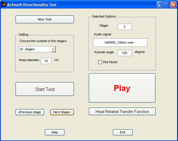
42 Figure 4.1- The "Azimuth Directionality Test" window 36
43 Entering the listener's head diameter is the next step. The operator has to measure the listener's head diameter before the test. As it was observed in above chapters all calculations are dependent the head radius. "Start test" starts the measuring with the first monaural digital audio signal at specified azimuth angle. All audio signals with pre-determined azimuth angles are in a database file. The binaural signals are played for the listener through the headphones by pressing the play button. If the pink noise checkbox is active, it means the binaural signal is in presence of noise. Finally it is possible to observe the plots of the HRTF that is corresponding the head radius and the azimuth angle. Figure 4.1 shows the appearance of the main window of the azimuth directionality test work bench. If the operator forgets entering any data, he/she receives an error message. 4.2 Test Requirements The directionality test needs some equipment. A computer, an ASIO compatible sound card and the driver software, Matlab software, calibration equipment, calculation, a test work bench and a test place. 37

44 4.2.1 The ASIO Sound Card The sound card used for sending out the binaural signals is "EDIROL UA-1EX". The sound card is an ASIO-compatible USB audio interface. It is possible to set the configuration working at 44100, 32000, and Hz sample rate. It has been designed to offer component-quality audio signals in and out of the computer. It has A/D and D/A converters. Figure 4.2 shows a UA- 1EX [15]. Figure 4.2- EDIROL UA-1EX The Matlab Audio Processing Framework The framework used in the thesis, MAP (Matlab Audio Processing), is a tool for low latency real-time audio signal processing within the Matlab environment. It has been developed by the acoustic research group at Blekinge Institute of Technology. It consists of a thin layer between any Audio Stream Input/Output (ASIO) compatible sound card and user defined scripts in Matlab. 38
.")
45 The frameworks presents sampled audio data from the sound card to the user in blocks, and the user processes the input signal to produce the output signal, which is presented to the sound card for playback. The framework is only limited by what the sound card in use can supply (for example the number of input and output channels, block size and sample rate). The framework allows development, evaluation and demonstration of algorithms in realtime within Matlab The Calibration Calibrating the headphones output has been done by the Acoustilyzer AL1. The Acoustilyzer is an audio test device with a wide range of acoustical measurement ability. The sound pressure level, speech intelligibility, and reverberation time are some of its functions [16]. Figure 4.3-The Acoustilyzer AL1 with the microphones Figure 4.3 shows an acoustilyzer AL1 with the related microphone. For calibrating the whole path from the binaural signal 39
46 generating to the headphone outputs, a 10 seconds, and 1 KHz pure tone has been generated. The audio signal had to be enough audible so the signal level at the output of every channel was 70 dba. The method was measuring the level of each channel output by the AL1 microphone when the signal was playing at 0 and 180, through a chamber. This calibration has to be repeated for every new test session and after changing every part of the test path (headphone, cables, sound card ) The Test Environment The environment was an acoustic classroom at a music house with 2-layer windows and a 2-layer door. The room was sound isolated. There was also a control room next by the classroom. The listeners sat in the classroom and the equipment were in the control room. There was an interface box between the classroom and the control room. There was also an interface box between these two rooms that had been installed on the wall. We could communicate through the interface. The binaural signals have also been played for the listeners through the interface. The room was approximately dark during the measurement. Listeners sat in the middle of the classroom, on a chair and next to a table. 40


47 Figure 4.4- The test environment. Top and left: the interface through the wall, bottom and left: a listener with headphone, window between the classroom and the control room, right: a 2-layer door. 41
48 42
49 5. The Directionality Test and The Error Calculation The last step of the project was binaural hearing measurement. The judged angles have been compared with the target angles and the judgments error have been calculated. 5.1 The Measurement Method In order to measure human's directionality tools mentioned in chapter 4, a measurement method has been designed. Listeners who wanted to discern the sound source direction had a guide semicircle shown in Figure 5.1. The Figure has divided the front semicircle into 18 partitions. The angle 0 is at the right ear and 180 is at the left ear. The listeners guessed the direction of the sound was played through the headphones. 5.2 The Test Procedure The binaural hearing test consists of two main categories of the stage numbers. It is always possible to change these numbers of stages as default. It is been determined a specified audio signal at specified direction. The number of the stages is chosen from the "azimuth directionality test" window in section 4.1 by the operator. 43
50 Figure 5.1- A semicircle of horizontal plane with 18 partitions The Test Signals The signals were combination of impulses, pure tones and speech, and in some stages in presence of pink noise. The impulses were 100 ms pure tones and the width of the pure tones was 2 seconds. The pink noise has been generated in Matlab and there were two uncorrelated random signals for two channels. The lowest frequency was 250 Hz and the highest was Hz. The sample rate frequency was Hz. 44
51 5.2.2 The Subjects The Binaural measuring test has been done in two different positions. In the first position 12 listeners participated. The population included 9 men and 3 women in the age from 21 to 62. Most of them were students in the age between 20 and 30 and and some of them had some experiences in mixing music. One of the subjects had changed his eardrum 14 years ago and he was 29 years old. One of the others was left handed and three of them wore eyeglasses. In the second test position 6 subjects participated. The population included 4 men and 2 women in age from 23 to 63. All subjects in both two experiments filled a form. The form consisted of some questions about their background ear problems and their profession. They also determined if they were left or right-handed and if they wore eyeglasses. In second position 7 listeners participated. The listeners included 2 women and 4 men in age from 21 and The Experiment Average Directionality Error The first measuring was a simple test with only linear differences in levels at the two ears without any frequency dependency and without any time arrival differences. The results are shown in Table
52 Subject Age Overall Average Error(degree) Impulses Error(degree) Continues Pure Tones Error(degree) Speech Error(degree) 1(m) (m)* (m) (m) (m) (m) (m) (f) (f) (f) (m) (m) Average Table 5.1-The results of the binaural hearing measurement with only simple differences in level without any frequency dependency and without calculating ITD, (m) =male and (f) =female. * This subject had changed his eardrum when he was 15 years old. The average errors and the errors in every category of signals have been calculated. 46
53 They heard some signals on top and behind the head through the headphones. The reason was illustrated in Figure Judged angle(degree) Targer angle(degree) Figure 5.2-The judged angles versus Target angles in test position 1 for only pure impulses Judged angle(degree) Targer angle(degree) Figure 5.3-The judged angles versus Target angles in test position1 for speech signals 47
54 Figure 5.2 and Figure 5.3 show the impulse and speech signals error for 7 listeners. The test condition was different in the second position. Both ILD and ITD in chapter 3 were used to create a binaural signal. The results are illustrated in Table 5.2. Subject Age Overall Average Error(degree) Impulses Error(degree) Continues Pure Tones Error(degree) Speech Error(degree) 1(f) (f) (m) (m) (m) (m) (m) Average Table 5.2- The results of the binaural hearing measurement with applying ILD and ITD to input digital audio signal, (m) =male and (f) =female. The subject 5 and 6 participated in both tests. The results illustrate that they have lower error in second test position The Audiogram A hearing loss test was provided for each listener by the software "Home Audiometer" and the listeners' audiograms was 48
55 obtained. The audiograms helped to find the relation between hearing loss and directionality practically. A few of the listeners had some degrees of hearing loss at high frequencies. One of them (subject 6 in Table 5.1) had a strange audiogram and could hear all frequencies at average level -18 dba. 5.4 Data Analysis The analysis of the data shows that the directionality at low frequencies is more accurate than high frequencies. It is also seen that directionality at the speech signals is much more accurate than the impulses and the pure tones. The error of the impulses is near to the overall average error and the pure tones error is much worse than the overall average error. The lowest error at speech signals is reasonable. The speech frequency band is up to 4 KHz and it can be considerable as a low frequency signal. Another reason can be the silence intervals in the speech signals. Human gets new ITD information after every silence time distance. It means the brain is updated with differences in levels and time arrivals information during listening to a speech signal. The results also show that having a good audiogram is necessary for having a good directionality, but it is not enough. The subjects who are old have noticeable directionality error. Telecommunication software and multimedia lab, Helsinki 49
56 University of Technology, has achieved 9.7 degrees average azimuth error [6]. Our test results with some basic equipment are comparable with the results obtained from an advanced laboratory. 5.5 Improvement The test procedures can be improved by changing some parts of the test. It is possible to measure directionality with presence of different kinds of noise and or stimuli. This test can also be done in an acoustic or absorbance room. The method of judging the sound source direction by listeners can be changed. There were two kinds of the guidance semicircles in the two different tests. But there are still some problems that cause built-in errors. 50
57 - Conclusion The thesis has approached to a method for measuring human ability in directionality. The directionality test was done with real human subjects. All parts of the thesis consist of studying and investigating recent models, choosing a model, implementing the model, designing GUI interface and directionality test had a one goal and it was achieving a systematical method in order to measure human ability in directionality. - Future Work Except some improvements that have been mentioned in section 5.5, the thesis can be continued by adding some other abilities. One work can be simulating a virtual room for getting online results and plotting the error results at the same time. Another work is adding other models such as pinna model, room model and inner ear model to SHM and getting more accurate results. Elevation directionality can also be added to azimuth directionality. 51
58 52
59 Appendix A: Some important functions that have been used in the virtual auditory model are explained in this section. **************************************************************************** function [h phasdelay]=fd_mf_fb(delay, sample_rate); Function FD_MF_FB designs fractional delay maximally flat allpass filter. Inputs: -delay = the delay in second that you need to create for every input audio signal - sample rate = the sample rate frequency in Hz %% delay*sample_rate must not be more than 200 outputs: - h: filter impulse response - phasdelay : group delay in samples **************************************************************************** function [direct_gain lateral_gain]=ild(az, hr) Function ILD calculates the interaural level differences in horizontal plane Inputs: - az = azimuth angle in horizontal plane and front semicircle in degree az=0 at right ear, az= 180 at left ear and az=90 in front of head - hr = Head radius in meter Outputs: - direct_gain = The filter amplitude in ipsilateral ear and it is a vector - lateral_gain = The filter amplitude in contralateral ear and it is a vector 53
60 **************************************************************************** function [direct_delay lateral_delay]=itd(az, dis, hr) Function ITD calculates the time arrivals of an audio signal from a sound source to both ears.. Inputs: - az = The angle between median plane and the line between the sound source and the center of head(degree) - dis = The distance between the sound source and the center of head(m) - hr = Head radius (m)(consider the head as a sphere) Outputs: - direct_delay = Time arrival at ipsilateral ear in sec - lateral_delay = Time arrival at contralateral ear in sec 54
61 References: [1] Brown C. P. and Duda R. O., 1998 "A structural model for binaural sound synthesis", IEEE Transaction on Speech and Audio Processing, vol. 6, No 5. [2] Brungart D. S. and Rabinowitz W. M., 1999 "Auditory localization of nearby sources. Head related transfer functions ", Acoustical Society of America. [3] Cheng C. A., 2001 " Visualization, Measurement, And Interpolation Of Head-Related Transfer Functions (HRTF S) With Applications In Electro-Acoustic Music ", Michigan University. [4] Daniel J., 2003 " Spatial Sound Encoding Including Near Field Effect: Introducing Distance Coding Filters and a Viable, New Ambisonic Format ", AES 23 rd International Conference, Copenhagen. [5] Duda R. O. and Martens W. L., 1998 "Range dependence of the response of a spherical head model". [6] Grö hn, M., Lokki, T., Savioja, L., 2001 "Using binaural hearing for localization in multimodal virtual environments", 17th International Congress on Acoustics, Rome. [7] Hartman W. M., 1999 "How we localize sound", America institute of Physics. 55
62 [8] Hartman W. M., 1983 "Localization of sound in rooms", Department of Physics, Michigan State University. [9] Hasegava H. and Matsumoto S., 1999 "Binaural sound reproduction using head-related transfer functions (HRTFs) approximated by IIR filters", IEEE TENCON. [10] Miller J. D., 2001 "Modeling interaural time difference assuming a spherical head", Musical Acoustic, Stanford University. [11] Pulkki V., Karjalainen M. and Huopaniemi J., 1999 "Analyzing virtual sound source attributes using a binaural auditory model", Helsinki University of Technology, Laboratory of Acoustic and Audio Signal Processing. [12] Stern R. N. and Trahiotis C., 1995 "Models of binaural perception", The Conference of Binaural and Spatial Hearing. [13] Visle H. and Evangelista G., 2004 "Binaural source localization", Conference of Digital Audio Effects, Naples, October 5-8. [14] Välimäki V., 1994 "Simple design of fractional delay allpass filters", Helsinki University of Technology, Laboratory of Acoustic and Audio Signal Processing. 56
63 [15] [16] [17] [18] 57
Sound Source Localization using HRTF database
 ICCAS June -, KINTEX, Gyeonggi-Do, Korea Sound Source Localization using HRTF database Sungmok Hwang*, Youngjin Park and Younsik Park * Center for Noise and Vibration Control, Dept. of Mech. Eng., KAIST,
Acoustics Research Institute
 Austrian Academy of Sciences Acoustics Research Institute Spatial SpatialHearing: Hearing: Single SingleSound SoundSource Sourcein infree FreeField Field Piotr PiotrMajdak Majdak&&Bernhard BernhardLaback
Computational Perception. Sound localization 2
 Computational Perception 15-485/785 January 22, 2008 Sound localization 2 Last lecture sound propagation: reflection, diffraction, shadowing sound intensity (db) defining computational problems sound lateralization
Auditory Localization
 Auditory Localization CMPT 468: Sound Localization Tamara Smyth, tamaras@cs.sfu.ca School of Computing Science, Simon Fraser University November 15, 2013 Auditory locatlization is the human perception
A Virtual Audio Environment for Testing Dummy- Head HRTFs modeling Real Life Situations
 A Virtual Audio Environment for Testing Dummy- Head HRTFs modeling Real Life Situations György Wersényi Széchenyi István University, Hungary. József Répás Széchenyi István University, Hungary. Summary
Intensity Discrimination and Binaural Interaction
 Technical University of Denmark Intensity Discrimination and Binaural Interaction 2 nd semester project DTU Electrical Engineering Acoustic Technology Spring semester 2008 Group 5 Troels Schmidt Lindgreen
Computational Perception /785
 Computational Perception 15-485/785 Assignment 1 Sound Localization due: Thursday, Jan. 31 Introduction This assignment focuses on sound localization. You will develop Matlab programs that synthesize sounds
A triangulation method for determining the perceptual center of the head for auditory stimuli
 A triangulation method for determining the perceptual center of the head for auditory stimuli PACS REFERENCE: 43.66.Qp Brungart, Douglas 1 ; Neelon, Michael 2 ; Kordik, Alexander 3 ; Simpson, Brian 4 1
The analysis of multi-channel sound reproduction algorithms using HRTF data
 The analysis of multichannel sound reproduction algorithms using HRTF data B. Wiggins, I. PatersonStephens, P. Schillebeeckx Processing Applications Research Group University of Derby Derby, United Kingdom
Convention Paper Presented at the 139th Convention 2015 October 29 November 1 New York, USA
 Audio Engineering Society Convention Paper Presented at the 139th Convention 2015 October 29 November 1 New York, USA 9447 This Convention paper was selected based on a submitted abstract and 750-word
University of Huddersfield Repository
 University of Huddersfield Repository Moore, David J. and Wakefield, Jonathan P. Surround Sound for Large Audiences: What are the Problems? Original Citation Moore, David J. and Wakefield, Jonathan P.
Convention Paper 9870 Presented at the 143 rd Convention 2017 October 18 21, New York, NY, USA
 Audio Engineering Society Convention Paper 987 Presented at the 143 rd Convention 217 October 18 21, New York, NY, USA This convention paper was selected based on a submitted abstract and 7-word precis
Enhancing 3D Audio Using Blind Bandwidth Extension
 Enhancing 3D Audio Using Blind Bandwidth Extension (PREPRINT) Tim Habigt, Marko Ðurković, Martin Rothbucher, and Klaus Diepold Institute for Data Processing, Technische Universität München, 829 München,
Sound source localization and its use in multimedia applications
 Notes for lecture/ Zack Settel, McGill University Sound source localization and its use in multimedia applications Introduction With the arrival of real-time binaural or "3D" digital audio processing,
PERSONALIZED HEAD RELATED TRANSFER FUNCTION MEASUREMENT AND VERIFICATION THROUGH SOUND LOCALIZATION RESOLUTION
 PERSONALIZED HEAD RELATED TRANSFER FUNCTION MEASUREMENT AND VERIFICATION THROUGH SOUND LOCALIZATION RESOLUTION Michał Pec, Michał Bujacz, Paweł Strumiłło Institute of Electronics, Technical University
Spatial Audio & The Vestibular System!
 ! Spatial Audio & The Vestibular System! Gordon Wetzstein! Stanford University! EE 267 Virtual Reality! Lecture 13! stanford.edu/class/ee267/!! Updates! lab this Friday will be released as a video! TAs
HRIR Customization in the Median Plane via Principal Components Analysis
 한국소음진동공학회 27 년춘계학술대회논문집 KSNVE7S-6- HRIR Customization in the Median Plane via Principal Components Analysis 주성분분석을이용한 HRIR 맞춤기법 Sungmok Hwang and Youngjin Park* 황성목 박영진 Key Words : Head-Related Transfer
Aalborg Universitet. Audibility of time switching in dynamic binaural synthesis Hoffmann, Pablo Francisco F.; Møller, Henrik
 Aalborg Universitet Audibility of time switching in dynamic binaural synthesis Hoffmann, Pablo Francisco F.; Møller, Henrik Published in: Journal of the Audio Engineering Society Publication date: 2005
A binaural auditory model and applications to spatial sound evaluation
 A binaural auditory model and applications to spatial sound evaluation Ma r k o Ta k a n e n 1, Ga ë ta n Lo r h o 2, a n d Mat t i Ka r ja l a i n e n 1 1 Helsinki University of Technology, Dept. of Signal
NEAR-FIELD VIRTUAL AUDIO DISPLAYS
 NEAR-FIELD VIRTUAL AUDIO DISPLAYS Douglas S. Brungart Human Effectiveness Directorate Air Force Research Laboratory Wright-Patterson AFB, Ohio Abstract Although virtual audio displays are capable of realistically
URBANA-CHAMPAIGN. CS 498PS Audio Computing Lab. 3D and Virtual Sound. Paris Smaragdis. paris.cs.illinois.
 UNIVERSITY ILLINOIS @ URBANA-CHAMPAIGN OF CS 498PS Audio Computing Lab 3D and Virtual Sound Paris Smaragdis paris@illinois.edu paris.cs.illinois.edu Overview Human perception of sound and space ITD, IID,
Robotic Spatial Sound Localization and Its 3-D Sound Human Interface
 Robotic Spatial Sound Localization and Its 3-D Sound Human Interface Jie Huang, Katsunori Kume, Akira Saji, Masahiro Nishihashi, Teppei Watanabe and William L. Martens The University of Aizu Aizu-Wakamatsu,
Spatial Audio Reproduction: Towards Individualized Binaural Sound
 Spatial Audio Reproduction: Towards Individualized Binaural Sound WILLIAM G. GARDNER Wave Arts, Inc. Arlington, Massachusetts INTRODUCTION The compact disc (CD) format records audio with 16-bit resolution
Convention Paper Presented at the 125th Convention 2008 October 2 5 San Francisco, CA, USA
 Audio Engineering Society Convention Paper Presented at the 125th Convention 2008 October 2 5 San Francisco, CA, USA The papers at this Convention have been selected on the basis of a submitted abstract
Audio Engineering Society. Convention Paper. Presented at the 129th Convention 2010 November 4 7 San Francisco, CA, USA. Why Ambisonics Does Work
 Audio Engineering Society Convention Paper Presented at the 129th Convention 2010 November 4 7 San Francisco, CA, USA The papers at this Convention have been selected on the basis of a submitted abstract
TDE-ILD-HRTF-Based 2D Whole-Plane Sound Source Localization Using Only Two Microphones and Source Counting
 TDE-ILD-HRTF-Based 2D Whole-Plane Sound Source Localization Using Only Two Microphones Source Counting Ali Pourmohammad, Member, IACSIT Seyed Mohammad Ahadi Abstract In outdoor cases, TDOA-based methods
Psychoacoustic Cues in Room Size Perception
 Audio Engineering Society Convention Paper Presented at the 116th Convention 2004 May 8 11 Berlin, Germany 6084 This convention paper has been reproduced from the author s advance manuscript, without editing,
Listening with Headphones
 Listening with Headphones Main Types of Errors Front-back reversals Angle error Some Experimental Results Most front-back errors are front-to-back Substantial individual differences Most evident in elevation
Study on method of estimating direct arrival using monaural modulation sp. Author(s)Ando, Masaru; Morikawa, Daisuke; Uno
Ando, Masaru; Morikawa, Daisuke; Uno") JAIST Reposi https://dspace.j Title Study on method of estimating direct arrival using monaural modulation sp Author(s)Ando, Masaru; Morikawa, Daisuke; Uno Citation Journal of Signal Processing, 18(4):
JAIST Reposi https://dspace.j Title Study on method of estimating direct arrival using monaural modulation sp Author(s)Ando, Masaru; Morikawa, Daisuke; Uno Citation Journal of Signal Processing, 18(4):
Analysis of Frontal Localization in Double Layered Loudspeaker Array System
 Proceedings of 20th International Congress on Acoustics, ICA 2010 23 27 August 2010, Sydney, Australia Analysis of Frontal Localization in Double Layered Loudspeaker Array System Hyunjoo Chung (1), Sang
Envelopment and Small Room Acoustics
 Envelopment and Small Room Acoustics David Griesinger Lexicon 3 Oak Park Bedford, MA 01730 Copyright 9/21/00 by David Griesinger Preview of results Loudness isn t everything! At least two additional perceptions:
Multiple Sound Sources Localization Using Energetic Analysis Method
 VOL.3, NO.4, DECEMBER 1 Multiple Sound Sources Localization Using Energetic Analysis Method Hasan Khaddour, Jiří Schimmel Department of Telecommunications FEEC, Brno University of Technology Purkyňova
Introduction. 1.1 Surround sound
 Introduction 1 This chapter introduces the project. First a brief description of surround sound is presented. A problem statement is defined which leads to the goal of the project. Finally the scope of
Binaural Hearing. Reading: Yost Ch. 12
 Binaural Hearing Reading: Yost Ch. 12 Binaural Advantages Sounds in our environment are usually complex, and occur either simultaneously or close together in time. Studies have shown that the ability to
THE DEVELOPMENT OF A DESIGN TOOL FOR 5-SPEAKER SURROUND SOUND DECODERS
 THE DEVELOPMENT OF A DESIGN TOOL FOR 5-SPEAKER SURROUND SOUND DECODERS by John David Moore A thesis submitted to the University of Huddersfield in partial fulfilment of the requirements for the degree
THE TEMPORAL and spectral structure of a sound signal
 IEEE TRANSACTIONS ON SPEECH AND AUDIO PROCESSING, VOL. 13, NO. 1, JANUARY 2005 105 Localization of Virtual Sources in Multichannel Audio Reproduction Ville Pulkki and Toni Hirvonen Abstract The localization
Ivan Tashev Microsoft Research
 Hannes Gamper Microsoft Research David Johnston Microsoft Research Ivan Tashev Microsoft Research Mark R. P. Thomas Dolby Laboratories Jens Ahrens Chalmers University, Sweden Augmented and virtual reality,
Audio Engineering Society. Convention Paper. Presented at the 131st Convention 2011 October New York, NY, USA
 Audio Engineering Society Convention Paper Presented at the 131st Convention 2011 October 20 23 New York, NY, USA This Convention paper was selected based on a submitted abstract and 750-word precis that
A CLOSER LOOK AT THE REPRESENTATION OF INTERAURAL DIFFERENCES IN A BINAURAL MODEL
 9th INTERNATIONAL CONGRESS ON ACOUSTICS MADRID, -7 SEPTEMBER 7 A CLOSER LOOK AT THE REPRESENTATION OF INTERAURAL DIFFERENCES IN A BINAURAL MODEL PACS: PACS:. Pn Nicolas Le Goff ; Armin Kohlrausch ; Jeroen
3D Sound Simulation over Headphones
 Lorenzo Picinali (lorenzo@limsi.fr or lpicinali@dmu.ac.uk) Paris, 30 th September, 2008 Chapter for the Handbook of Research on Computational Art and Creative Informatics Chapter title: 3D Sound Simulation
INVESTIGATING BINAURAL LOCALISATION ABILITIES FOR PROPOSING A STANDARDISED TESTING ENVIRONMENT FOR BINAURAL SYSTEMS
 20-21 September 2018, BULGARIA 1 Proceedings of the International Conference on Information Technologies (InfoTech-2018) 20-21 September 2018, Bulgaria INVESTIGATING BINAURAL LOCALISATION ABILITIES FOR
The psychoacoustics of reverberation
 The psychoacoustics of reverberation Steven van de Par Steven.van.de.Par@uni-oldenburg.de July 19, 2016 Thanks to Julian Grosse and Andreas Häußler 2016 AES International Conference on Sound Field Control
Direction-Dependent Physical Modeling of Musical Instruments
 15th International Congress on Acoustics (ICA 95), Trondheim, Norway, June 26-3, 1995 Title of the paper: Direction-Dependent Physical ing of Musical Instruments Authors: Matti Karjalainen 1,3, Jyri Huopaniemi
Binaural hearing. Prof. Dan Tollin on the Hearing Throne, Oldenburg Hearing Garden
 Binaural hearing Prof. Dan Tollin on the Hearing Throne, Oldenburg Hearing Garden Outline of the lecture Cues for sound localization Duplex theory Spectral cues do demo Behavioral demonstrations of pinna
Audio Engineering Society. Convention Paper. Presented at the 124th Convention 2008 May Amsterdam, The Netherlands
 Audio Engineering Society Convention Paper Presented at the 124th Convention 2008 May 17 20 Amsterdam, The Netherlands The papers at this Convention have been selected on the basis of a submitted abstract
Convention e-brief 400
 Audio Engineering Society Convention e-brief 400 Presented at the 143 rd Convention 017 October 18 1, New York, NY, USA This Engineering Brief was selected on the basis of a submitted synopsis. The author
PERSONAL 3D AUDIO SYSTEM WITH LOUDSPEAKERS
 PERSONAL 3D AUDIO SYSTEM WITH LOUDSPEAKERS Myung-Suk Song #1, Cha Zhang 2, Dinei Florencio 3, and Hong-Goo Kang #4 # Department of Electrical and Electronic, Yonsei University Microsoft Research 1 earth112@dsp.yonsei.ac.kr,
Reproduction of Surround Sound in Headphones
 Reproduction of Surround Sound in Headphones December 24 Group 96 Department of Acoustics Faculty of Engineering and Science Aalborg University Institute of Electronic Systems - Department of Acoustics
THE MATLAB IMPLEMENTATION OF BINAURAL PROCESSING MODEL SIMULATING LATERAL POSITION OF TONES WITH INTERAURAL TIME DIFFERENCES
 THE MATLAB IMPLEMENTATION OF BINAURAL PROCESSING MODEL SIMULATING LATERAL POSITION OF TONES WITH INTERAURAL TIME DIFFERENCES J. Bouše, V. Vencovský Department of Radioelectronics, Faculty of Electrical
MANY emerging applications require the ability to render
 IEEE TRANSACTIONS ON MULTIMEDIA, VOL. 6, NO. 4, AUGUST 2004 553 Rendering Localized Spatial Audio in a Virtual Auditory Space Dmitry N. Zotkin, Ramani Duraiswami, Member, IEEE, and Larry S. Davis, Fellow,
BINAURAL RECORDING SYSTEM AND SOUND MAP OF MALAGA
 EUROPEAN SYMPOSIUM ON UNDERWATER BINAURAL RECORDING SYSTEM AND SOUND MAP OF MALAGA PACS: Rosas Pérez, Carmen; Luna Ramírez, Salvador Universidad de Málaga Campus de Teatinos, 29071 Málaga, España Tel:+34
On distance dependence of pinna spectral patterns in head-related transfer functions
 On distance dependence of pinna spectral patterns in head-related transfer functions Simone Spagnol a) Department of Information Engineering, University of Padova, Padova 35131, Italy spagnols@dei.unipd.it
ORIENTATION IN SIMPLE VIRTUAL AUDITORY SPACE CREATED WITH MEASURED HRTF
 ORIENTATION IN SIMPLE VIRTUAL AUDITORY SPACE CREATED WITH MEASURED HRTF F. Rund, D. Štorek, O. Glaser, M. Barda Faculty of Electrical Engineering Czech Technical University in Prague, Prague, Czech Republic
Binaural Audio Project
 UNIVERSITY OF EDINBURGH School of Physics and Astronomy Binaural Audio Project Roberto Becerra MSc Acoustics and Music Technology S1034048 s1034048@sms.ed.ac.uk 17 March 11 ABSTRACT The aim of this project
Sound localization Sound localization in audio-based games for visually impaired children
 Sound localization Sound localization in audio-based games for visually impaired children R. Duba B.W. Kootte Delft University of Technology SOUND LOCALIZATION SOUND LOCALIZATION IN AUDIO-BASED GAMES
Evaluation of a new stereophonic reproduction method with moving sweet spot using a binaural localization model
 Evaluation of a new stereophonic reproduction method with moving sweet spot using a binaural localization model Sebastian Merchel and Stephan Groth Chair of Communication Acoustics, Dresden University
Proceedings of Meetings on Acoustics
 Proceedings of Meetings on Acoustics Volume 1, 21 http://acousticalsociety.org/ ICA 21 Montreal Montreal, Canada 2 - June 21 Psychological and Physiological Acoustics Session appb: Binaural Hearing (Poster
Virtual Acoustic Space as Assistive Technology
 Multimedia Technology Group Virtual Acoustic Space as Assistive Technology Czech Technical University in Prague Faculty of Electrical Engineering Department of Radioelectronics Technická 2 166 27 Prague
DISTANCE CODING AND PERFORMANCE OF THE MARK 5 AND ST350 SOUNDFIELD MICROPHONES AND THEIR SUITABILITY FOR AMBISONIC REPRODUCTION
 DISTANCE CODING AND PERFORMANCE OF THE MARK 5 AND ST350 SOUNDFIELD MICROPHONES AND THEIR SUITABILITY FOR AMBISONIC REPRODUCTION T Spenceley B Wiggins University of Derby, Derby, UK University of Derby,
Sound Radiation Characteristic of a Shakuhachi with different Playing Techniques
 Sound Radiation Characteristic of a Shakuhachi with different Playing Techniques T. Ziemer University of Hamburg, Neue Rabenstr. 13, 20354 Hamburg, Germany tim.ziemer@uni-hamburg.de 549 The shakuhachi,
HRTF adaptation and pattern learning
 HRTF adaptation and pattern learning FLORIAN KLEIN * AND STEPHAN WERNER Electronic Media Technology Lab, Institute for Media Technology, Technische Universität Ilmenau, D-98693 Ilmenau, Germany The human
ROOM AND CONCERT HALL ACOUSTICS MEASUREMENTS USING ARRAYS OF CAMERAS AND MICROPHONES
 ROOM AND CONCERT HALL ACOUSTICS The perception of sound by human listeners in a listening space, such as a room or a concert hall is a complicated function of the type of source sound (speech, oration,
We are IntechOpen, the world s leading publisher of Open Access books Built by scientists, for scientists. International authors and editors
 We are IntechOpen, the world s leading publisher of Open Access books Built by scientists, for scientists 3,700 108,500 1.7 M Open access books available International authors and editors Downloads Our
ROOM SHAPE AND SIZE ESTIMATION USING DIRECTIONAL IMPULSE RESPONSE MEASUREMENTS
 ROOM SHAPE AND SIZE ESTIMATION USING DIRECTIONAL IMPULSE RESPONSE MEASUREMENTS PACS: 4.55 Br Gunel, Banu Sonic Arts Research Centre (SARC) School of Computer Science Queen s University Belfast Belfast,
University of Huddersfield Repository
 University of Huddersfield Repository Lee, Hyunkook Capturing and Rendering 360º VR Audio Using Cardioid Microphones Original Citation Lee, Hyunkook (2016) Capturing and Rendering 360º VR Audio Using Cardioid
Speech Compression. Application Scenarios
 Speech Compression Application Scenarios Multimedia application Live conversation? Real-time network? Video telephony/conference Yes Yes Business conference with data sharing Yes Yes Distance learning
Final Exam Study Guide: Introduction to Computer Music Course Staff April 24, 2015
 Final Exam Study Guide: 15-322 Introduction to Computer Music Course Staff April 24, 2015 This document is intended to help you identify and master the main concepts of 15-322, which is also what we intend
Modeling Head-Related Transfer Functions Based on Pinna Anthropometry
 Second LACCEI International Latin American and Caribbean Conference for Engineering and Technology (LACCEI 24) Challenges and Opportunities for Engineering Education, Research and Development 2-4 June
SOUND 1 -- ACOUSTICS 1
 SOUND 1 -- ACOUSTICS 1 SOUND 1 ACOUSTICS AND PSYCHOACOUSTICS SOUND 1 -- ACOUSTICS 2 The Ear: SOUND 1 -- ACOUSTICS 3 The Ear: The ear is the organ of hearing. SOUND 1 -- ACOUSTICS 4 The Ear: The outer ear
III. Publication III. c 2005 Toni Hirvonen.
 III Publication III Hirvonen, T., Segregation of Two Simultaneously Arriving Narrowband Noise Signals as a Function of Spatial and Frequency Separation, in Proceedings of th International Conference on
THE PERCEPTION OF ALL-PASS COMPONENTS IN TRANSFER FUNCTIONS
 PACS Reference: 43.66.Pn THE PERCEPTION OF ALL-PASS COMPONENTS IN TRANSFER FUNCTIONS Pauli Minnaar; Jan Plogsties; Søren Krarup Olesen; Flemming Christensen; Henrik Møller Department of Acoustics Aalborg
Sound Processing Technologies for Realistic Sensations in Teleworking
 Sound Processing Technologies for Realistic Sensations in Teleworking Takashi Yazu Makoto Morito In an office environment we usually acquire a large amount of information without any particular effort
I R UNDERGRADUATE REPORT. Stereausis: A Binaural Processing Model. by Samuel Jiawei Ng Advisor: P.S. Krishnaprasad UG
 UNDERGRADUATE REPORT Stereausis: A Binaural Processing Model by Samuel Jiawei Ng Advisor: P.S. Krishnaprasad UG 2001-6 I R INSTITUTE FOR SYSTEMS RESEARCH ISR develops, applies and teaches advanced methodologies
3D Sound System with Horizontally Arranged Loudspeakers
 3D Sound System with Horizontally Arranged Loudspeakers Keita Tanno A DISSERTATION SUBMITTED IN FULFILLMENT OF THE REQUIREMENTS FOR THE DEGREE OF DOCTOR OF PHILOSOPHY IN COMPUTER SCIENCE AND ENGINEERING
3D sound image control by individualized parametric head-related transfer functions
 D sound image control by individualized parametric head-related transfer functions Kazuhiro IIDA 1 and Yohji ISHII 1 Chiba Institute of Technology 2-17-1 Tsudanuma, Narashino, Chiba 275-001 JAPAN ABSTRACT
SOPA version 2. Revised July SOPA project. September 21, Introduction 2. 2 Basic concept 3. 3 Capturing spatial audio 4
 SOPA version 2 Revised July 7 2014 SOPA project September 21, 2014 Contents 1 Introduction 2 2 Basic concept 3 3 Capturing spatial audio 4 4 Sphere around your head 5 5 Reproduction 7 5.1 Binaural reproduction......................
Spatial audio is a field that
 [applications CORNER] Ville Pulkki and Matti Karjalainen Multichannel Audio Rendering Using Amplitude Panning Spatial audio is a field that investigates techniques to reproduce spatial attributes of sound
396 IEEE TRANSACTIONS ON AUDIO, SPEECH, AND LANGUAGE PROCESSING, VOL. 19, NO. 2, FEBRUARY 2011
 396 IEEE TRANSACTIONS ON AUDIO, SPEECH, AND LANGUAGE PROCESSING, VOL. 19, NO. 2, FEBRUARY 2011 Obtaining Binaural Room Impulse Responses From B-Format Impulse Responses Using Frequency-Dependent Coherence
6-channel recording/reproduction system for 3-dimensional auralization of sound fields
 Acoust. Sci. & Tech. 23, 2 (2002) TECHNICAL REPORT 6-channel recording/reproduction system for 3-dimensional auralization of sound fields Sakae Yokoyama 1;*, Kanako Ueno 2;{, Shinichi Sakamoto 2;{ and
AN AUDITORILY MOTIVATED ANALYSIS METHOD FOR ROOM IMPULSE RESPONSES
 Proceedings of the COST G-6 Conference on Digital Audio Effects (DAFX-), Verona, Italy, December 7-9,2 AN AUDITORILY MOTIVATED ANALYSIS METHOD FOR ROOM IMPULSE RESPONSES Tapio Lokki Telecommunications
Proceedings of Meetings on Acoustics
 Proceedings of Meetings on Acoustics Volume 19, 2013 http://acousticalsociety.org/ ICA 2013 Montreal Montreal, Canada 2-7 June 2013 Architectural Acoustics Session 1pAAa: Advanced Analysis of Room Acoustics:
Improving room acoustics at low frequencies with multiple loudspeakers and time based room correction
 Improving room acoustics at low frequencies with multiple loudspeakers and time based room correction S.B. Nielsen a and A. Celestinos b a Aalborg University, Fredrik Bajers Vej 7 B, 9220 Aalborg Ø, Denmark
Jason Schickler Boston University Hearing Research Center, Department of Biomedical Engineering, Boston University, Boston, Massachusetts 02215
 Spatial unmasking of nearby speech sources in a simulated anechoic environment Barbara G. Shinn-Cunningham a) Boston University Hearing Research Center, Departments of Cognitive and Neural Systems and
Effects of Reverberation on Pitch, Onset/Offset, and Binaural Cues
 Effects of Reverberation on Pitch, Onset/Offset, and Binaural Cues DeLiang Wang Perception & Neurodynamics Lab The Ohio State University Outline of presentation Introduction Human performance Reverberation
Audio Engineering Society. Convention Paper. Presented at the 115th Convention 2003 October New York, New York
 Audio Engineering Society Convention Paper Presented at the 115th Convention 2003 October 10 13 New York, New York This convention paper has been reproduced from the author's advance manuscript, without
NAME STUDENT # ELEC 484 Audio Signal Processing. Midterm Exam July Listening test
 NAME STUDENT # ELEC 484 Audio Signal Processing Midterm Exam July 2008 CLOSED BOOK EXAM Time 1 hour Listening test Choose one of the digital audio effects for each sound example. Put only ONE mark in each
APPLICATIONS OF A DIGITAL AUDIO-SIGNAL PROCESSOR IN T.V. SETS
 Philips J. Res. 39, 94-102, 1984 R 1084 APPLICATIONS OF A DIGITAL AUDIO-SIGNAL PROCESSOR IN T.V. SETS by W. J. W. KITZEN and P. M. BOERS Philips Research Laboratories, 5600 JA Eindhoven, The Netherlands
SOPA version 3. SOPA project. July 22, Principle Introduction Direction of propagation Speed of propagation...
 SOPA version 3 SOPA project July 22, 2015 Contents 1 Principle 2 1.1 Introduction............................ 2 1.2 Direction of propagation..................... 3 1.3 Speed of propagation.......................
Virtual Sound Source Positioning and Mixing in 5.1 Implementation on the Real-Time System Genesis
 Virtual Sound Source Positioning and Mixing in 5 Implementation on the Real-Time System Genesis Jean-Marie Pernaux () Patrick Boussard () Jean-Marc Jot (3) () and () Steria/Digilog SA, Aix-en-Provence
Proceedings of Meetings on Acoustics
 Proceedings of Meetings on Acoustics Volume 19, 213 http://acousticalsociety.org/ ICA 213 Montreal Montreal, Canada 2-7 June 213 Signal Processing in Acoustics Session 2aSP: Array Signal Processing for
19 th INTERNATIONAL CONGRESS ON ACOUSTICS MADRID, 2-7 SEPTEMBER 2007 VIRTUAL AUDIO REPRODUCED IN A HEADREST
 19 th INTERNATIONAL CONGRESS ON ACOUSTICS MADRID, 2-7 SEPTEMBER 2007 VIRTUAL AUDIO REPRODUCED IN A HEADREST PACS: 43.25.Lj M.Jones, S.J.Elliott, T.Takeuchi, J.Beer Institute of Sound and Vibration Research;
4.5 Fractional Delay Operations with Allpass Filters
 158 Discrete-Time Modeling of Acoustic Tubes Using Fractional Delay Filters 4.5 Fractional Delay Operations with Allpass Filters The previous sections of this chapter have concentrated on the FIR implementation
Measuring impulse responses containing complete spatial information ABSTRACT
 Measuring impulse responses containing complete spatial information Angelo Farina, Paolo Martignon, Andrea Capra, Simone Fontana University of Parma, Industrial Eng. Dept., via delle Scienze 181/A, 43100
Auditory Distance Perception. Yan-Chen Lu & Martin Cooke
 Auditory Distance Perception Yan-Chen Lu & Martin Cooke Human auditory distance perception Human performance data (21 studies, 84 data sets) can be modelled by a power function r =kr a (Zahorik et al.
FIR/Convolution. Visulalizing the convolution sum. Convolution
 FIR/Convolution CMPT 368: Lecture Delay Effects Tamara Smyth, tamaras@cs.sfu.ca School of Computing Science, Simon Fraser University April 2, 27 Since the feedforward coefficient s of the FIR filter are
3D audio overview : from 2.0 to N.M (?)
") 3D audio overview : from 2.0 to N.M (?) Orange Labs Rozenn Nicol, Research & Development, 10/05/2012, Journée de printemps de la Société Suisse d Acoustique "Audio 3D" SSA, AES, SFA Signal multicanal 3D
3D audio overview : from 2.0 to N.M (?) Orange Labs Rozenn Nicol, Research & Development, 10/05/2012, Journée de printemps de la Société Suisse d Acoustique "Audio 3D" SSA, AES, SFA Signal multicanal 3D
Creating three dimensions in virtual auditory displays *
 Salvendy, D Harris, & RJ Koubek (eds.), (Proc HCI International 2, New Orleans, 5- August), NJ: Erlbaum, 64-68. Creating three dimensions in virtual auditory displays * Barbara Shinn-Cunningham Boston
c 2014 Michael Friedman
 c 2014 Michael Friedman CAPTURING SPATIAL AUDIO FROM ARBITRARY MICROPHONE ARRAYS FOR BINAURAL REPRODUCTION BY MICHAEL FRIEDMAN THESIS Submitted in partial fulfillment of the requirements for the degree
Week 1. Signals & Systems for Speech & Hearing. Sound is a SIGNAL 3. You may find this course demanding! How to get through it:
 Signals & Systems for Speech & Hearing Week You may find this course demanding! How to get through it: Consult the Web site: www.phon.ucl.ac.uk/courses/spsci/sigsys (also accessible through Moodle) Essential
IMPROVED COCKTAIL-PARTY PROCESSING
 IMPROVED COCKTAIL-PARTY PROCESSING Alexis Favrot, Markus Erne Scopein Research Aarau, Switzerland postmaster@scopein.ch Christof Faller Audiovisual Communications Laboratory, LCAV Swiss Institute of Technology