Industrial Miniature Circuit-Breakers S 220 series
|
|
|
- Winifred Harrell
- 6 years ago
- Views:
Transcription


1 Technical Data System pro M Industrial Miniature Circuit-Breakers System pro M 1
2 When connecting aluminum conductors, ensure that the contact surfaces of the conductors are cleaned, brushed and greased. For finely stranded conductors, use a connector sleeve for best results. Standard Terms for Delivery and Sale For domestic business, the Standard Terms for the Supply of Products and Services of the Electrical Industry (ABB Form 2292) shall apply in connection with the Standard Sale Terms (ABB Form 2327) in their then applicable version. For foreign business, the Standard Terms for the Supply of Products and Services of the Electrical Industry (ABB Form 2293 German/English, or ABB Form 2294 German/ French) shall apply in connection with the Standard Sales Terms (ABB Form 2381 English) in their then applicable version. Warranty We assume warranty in accordance with the standard sale and delivery terms. Complaints shall be made in writing within eight days following receipt of the goods. Technical information is not binding and subject to change without notice. 2
3 Content page Technical features Description... 4 Technical data... 5 Tripping behavior... 6 Short-circuit capacity... 6 Current-carrying capacity depending on the ambient temperature... 7 Mutual thermal influence... 7 Maximum back-up protection, overload selectivity and short-circuit selectivity. 8 Selection tables Miniature circuit-breakers S Auxiliary switches S 220-H Accessories Installation materials Accessories Busbars Technical data, current-carrying capacity Busbars Selection table Busbars Installation parts Installation and operation instructions Practical examples Installation and wiring diagrams Dimensions Drawings and tables
4 Special features for operating voltage up to 690 V AC disconnector abilities according to DIN VDE 0660 Part 107, IEC surge withstand capability Uimp (1.2/50): 4 kv can be used as main circuit breaker according to DIN VDE 0660 Part 101, IEC through individual position indication for each pole, red = ON, green = OFF comprehensive protection against electric shock locking device available as accessory General 1. Description The S 220 industrial miniature circuit-breaker has a current-limiting effect. Each pole contains two different trip releases acting on the joint contact mechanism: 2. Task 1. the delayed, thermal trip release for overcurrent protection, 2. the electro-magnetic instantaneous release for short-circuit protection. Protection against excessive temperature rises of electric items in the case of overcurrents, caused by overload, short circuit or earth-fault current. Resistance against electric shock in the case of excessive touch voltage caused by insulation fault if assigned and installed according to DIN VDE 0100, IEC Application In installation, switch, controlling and measuring units for commerical and industrial apparatus up to 690 V AC (UL/CSA approval up to 600 V AC as supplementary protector). 4. K-type characteristic for line and device protection Operating current 0.2 to 63 A, in 19 grades. Motor protection is reached selecting the operating current appropriate for the individual motor data. The electromagnetic trip releases are calibrated to avoid nuisance tripping caused by starting currents. In circuits with groups of filament lamps, mains shunt compensated fluorescent lamps or other discharge lamps, the conductor cross section to be protected can be used more efficiently as compared to miniature circuit-breakers with the same operating current, trip characteristics type B and C, considering the starting current. By reason of the smaller thermal threshold current value, the operating current can be assigned directly to the admissible current-carrying capacity according to DIN VDE 0298 Part 4, IEC As a result, it is usually possible to select a higher current-intensity grade than in the case of miniature circuit-breakers with B-type characteristics. 5. Additional devices Auxiliary switch 1 NO + 1 NC ( = H 11) for retrofitting, convertable to 2 NO or 2 NC. For switching auxiliary current circuits, depending on the switching position of the miniature circuit-breaker; with 2 galvanically separated devices. Through coupling the device with the contact mechanism, the auxiliary switch remains trip-free. The ABB miniature circuit-breaker has a current-limiting effect. Compared to zero-point self-extinguishing miniature circuit-breakers, S 220 offers three main advantages: higher short-circuit capacity improved back-up selectivity lines and defective sectors are subject to a significantly smaller let-through value ƒi2 dt. Current-limiting circuit-breaker by ABB Zero-point extinguishing miniature circuit-breaker U N = mains voltage U B = arc voltage SK 0175 Z 96 I K = let-through shortcircuit current I K = prospective short-circuit current SK 0537 Z 93 4
5 Technical data No. of poles: 1-, 2- and 3-pole specifications: IEC , rated current I n : 0.2 to 63 A internal nominal internal resistance power loss resistance: current per pole per pole I n /A m W connection: terminals: individual or busbar combined box terminal with M5 screw connection capacity (Cu): 1 x 25 mm 2 or 2 x 10 mm 2 for finely stranded to massive conductors min. cross section 1 mm 2 protection according to IEC 60529, EN 60529, VDE 0470: IP 20 size: DIN , frame size 1 depth of device: 83 mm dimensions: see illustrations on page 15 mounting position: fixing: climatic resistance: according to DIN or, as applicable, IEC 60068: optional snap-on onto DIN rails- EN , 35 mm width, screw fixing by means of mounting plate(see Accessories) constant climate 23/83, 40/93, 55/20 ( C/Rh) alternating climate (24 h cycle) 25/95 40/93 ( C/Rh) ambient temperature: T max + 55 C, T min 25 C shock resistance: vibration resistance: mechanical service life: service life at rated load and operating voltage: 10 g at least 20 impacts shock duration 13 ms 5 g, at least 30 minutes 20,000 operations 20,000 operations, I n 0,2 32 A 4,000 operations, I n A specifications: VDE 0660, IEC operating voltage U n : 1-pole 400/690 V 60 V... multi-pole 690 V 110 V... The tripping values for electromagnetic trip releases are valid for AC values from 16 2 /3 to 60 Hz. Deviating frequencies or DC current will cause the tripping characteristics to change as is indicated in the table on page 6. min. rated 12 V, 12 V... voltage U Bmin : (with respect to contact stability) insulation group acc. to former VDE 0110: pollution degree 2 trip-free mechanism: C at 500 V B at 750 V miniature circuit-breaker and auxiliary switch housing: plastic, gray RAL 7035 operating lever: } compareable to overvoltage category III black, in ON and OFF position sealable; lockable with lock adapter (see Accessories) Auxiliary switch S 220-H 11 terminal: M 3.5 screw with captive clamping washer connection capacity (Cu): 2 x mm mm 2 with connector sleeve permanent currenti th2 : rated current I n at: min. switching capacity: 5 A 220 V : 5 A 400 V : 2 A 60 V... : 2 A 110 V... : 1.5 A 250 V... : 1 A 5 VA 5
6 Tripping characteristics standard thermal trip electromagnetic trip ➁ tripping characteristic tripping currents: tripping time tripping currents: tripping time and rated current range conv.non-trip. conventional hold trips (ref. reference range) current trip. current impacts at the latest I 1 I 2 from at IEC/EN I n > 2 h 8 I n > 0.2 s 1.2 I n < 2 h ➀ K 0.2 to 63 A 1.5 I n < 2 min ➀ 6.0 I n > 2 s (T I ) 14 I n < 0.2 s ➀ as from operating temperature(after I 1 > 2 h). ➁ Frequency influence of electromagnetic trips The tripping values indicated for electromagnetic trips apply to a frequency of 16 2 /3 60 Hz. Deviating frequencies or DC current will cause the tripping characteristics to change by the factor indicated in the following table. AC 100 Hz 200 Hz 400 Hz factor ca tripping values of thermal trips are frequency-independent. DC Characteristics SK 0136 Z 00 SK 0138 Z 00 SK 0140 Z 00 S 220-K 0,2 8 A K A S 220-K A S 220-K A Short circuit capacity according to IEC/EN nominal AC DC currentrange 1-phase 2/3-phase 1-pole up to 133 V 230 V 400 V 133/230 V 230/400 V 290/500 V 400/690 V up to 60 V ➄ 0.2 up to 1 A unlimited unlimited unlimited unlimited unlimited unlimited unlimited unlimited 1.6 and 2 A unlimited unlimited 1.5 ka unlimited unlimited 6 ka 1.5 ka unlimited cos ϕ = 0.95 cos ϕ = 0.7 cos ϕ = and 4 A 15 ka 4.5 ka 1.5 ka 15 ka 4.5 ka 3 ka 1.5 ka 8 ka cos ϕ = 0.3 cos ϕ = 0.8 cos ϕ = 0.95 cos ϕ = 0.3 cos ϕ = 0.8 cos ϕ = 0.9 cos ϕ = 0.95 T 13 ms 6 and 8 A 15 ka 6 ka 1.5 ka 15 ka 6 ka 4.5 ka 1.5 ka 8 ka cos ϕ = 0.3 cos ϕ = 0.7 cos ϕ = 0.95 cos ϕ = 0.3 cos ϕ = 0.7 cos ϕ = 0.8 cos ϕ = 0.95 T 13 ms 10 up to 32 A 30 ka 10 ka 6 ka 30 ka 10 ka 10 ka 6 ka 8 ka cos ϕ = 0.25 cos ϕ = 0.5 cos ϕ = 0.7 cos ϕ = 0.25 cos ϕ = 0.5 cos ϕ = 0.5 cos ϕ = 0.7 T 13 ms 40 up to 63 A 6 ka 4.5 ka 3 ka 6 ka 4.5 ka 4.5 ka 3 ka 6 ka cos ϕ = 0.7 cos ϕ = 0.8 cos ϕ = 0.9 cos ϕ = 0.7 cos ϕ = 0.8 cos ϕ = 0.9 cos ϕ = 0.9 T 13 ms ➄ In symmetrically earthed DC circuits, S 222 two-pole devices (two poles connected in series) can be used up to 110 V DC. In this case, the short-circuit capacity is one grade above the 1-pole version (10 ka instead of 8 ka). Any connection is possible, polarity does not need to be taken into account. 6
7 Current-carrying capacity I/In depending on ambient temperature ϑ R ➀ possible load with a given ambient temperature of + 20 C. SK 0187 Z 96 Example: A K6 miniature circuit-breaker is used in an ambient temperature of + 40 C. What maximum current is possible? From the chart, you can see: I/I n = 0.93 I = = 5.58 A Mutual thermal influence of miniature circuit-breakers connected in series device spacing = 0. trip characteristic K of miniature circuit-breakers depending on device spacing (at least 7 devices in a row) trip characteristic K SK 0188 Z 96 SK 0189 Z 96 ➀ measured in open air ➁ measured in flush-mounted consumer unit x spacing Example: If 8 devices are connected in series, the max. possible permanent current is reduced to 0.77 x I n. Example: When connecting several devices in series with a spacing of 6 mm, the max. possible permanent current is reduced to 0.95 = I n (installed in open air) 0.9 = I n (installed in consumer unit) 7
8 Maximum back-up protection Maximum back-up protection is necessary only if the solid short-circuit current to be expected at the place of installation may exceed the short-circuit capacity. maximum back-up protection nominal current MCBs S 220-K circuitbreaker 230/400 V 230/400 V 400/690 V S 220 to main c.b.s max. back-up prot. max. back-up prot. I n S 700 E and K 1) gl gl A A A A optional optional optional optional optional optional optional optional ) Back-up protection up to at least 25 ka Short-circuit discrimination If the short circuit current does not exceed the nominal switching capacity of the miniature circuit-breaker, selectivity exists up to the values indicated. At U n 133/230 V, selectivity exists up to the short circuit current indicated. See also page 4. For cases where the max. back-up protection exceeds the nominal switching capacity, see above Short circuit discrimination in ka Short circuit discrimination in ka to main miniature circuit-breakers S 700 E sel and K to main miniature circuit-breaker S 700-E/-K 230/400 V SK 0048 Z 97 to fuse gl/gg (DIN VDE 0636, IEC 269/3) to fuse charact. gl/gg S 220 K In/A > 15 > 15 > 15 > 15 > 15 > 15 > 15 > 15 > > 15 > 15 > 15 > 15 > 15 > ** / ** limited or no selectivity possible in overload range (therm. tripping) SK 0087 Z 95 8


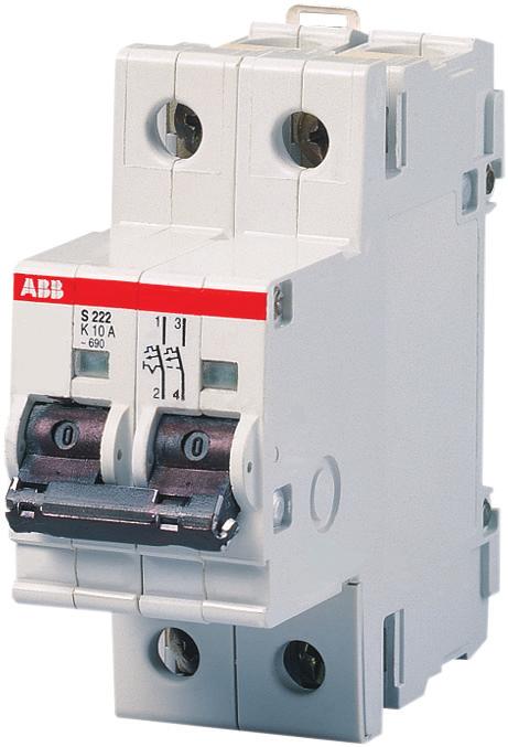
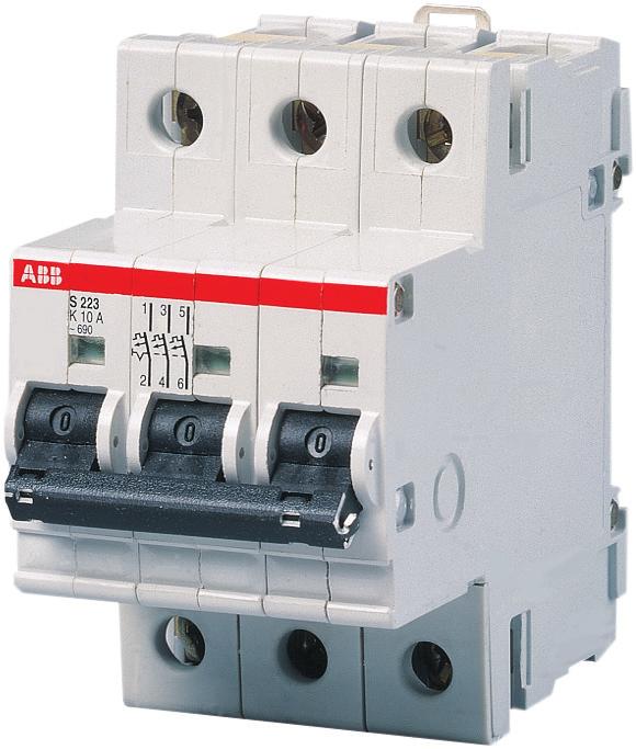
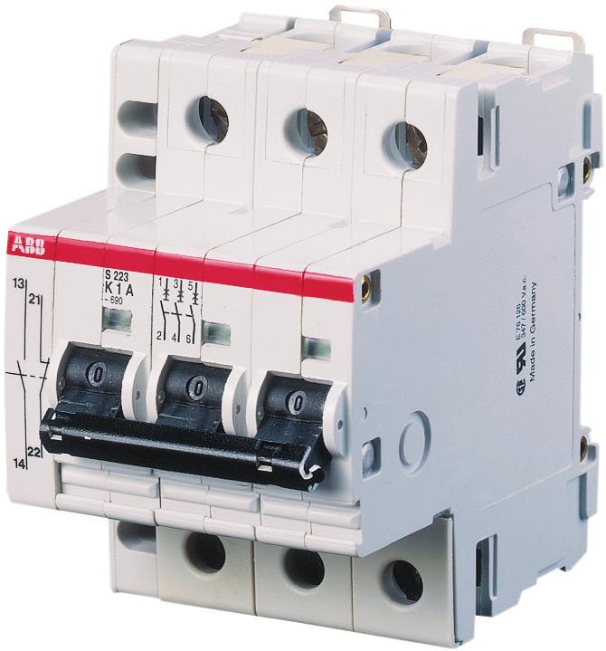
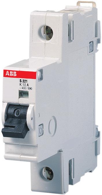
9 High performance miniature circuit-breakers K Selection table Kaccording to IEC/EN for power circuits, motors, transformers, lamps and for line protection S 221 S 222 S 223 S 220-H 11 SK 0194 B 91 SK 0193 B 91 SK 0192 B 91 SK 0191 B91 No. of rated order details bbn price price weight pack. poles current piece group 1 pc. units In A type code order code EAN kg pc. 1 U n 690 V 60 V... 2 U n 690 V 125 V... 3 U n 690 V 0.2 S 221-K 0.2 GHS R S 221-K 0.3 GHS R S 221-K 0.5 GHS R S 221-K 0.75 GHS R S 221-K 1 GHS R S 221-K 1.6 GHS R S 221-K 2 GHS R S 221-K 3 GHS R S 221-K 4 GHS R S 221-K 6 GHS R S 221-K 8 GHS R S 221-K 10 GHS R S 221-K 16 GHS R S 221-K 20 GHS R S 221-K 25 GHS R S 221-K 32 GHS R S 221-K 40 GHS R S 221-K 50 GHS R S 221-K 63 GHS R S 222-K 0.2 GHS R S 222-K 0.3 GHS R S 222-K 0.5 GHS R S 222-K 0.75 GHS R S 222-K 1 GHS R S 222-K 1.6 GHS R S 222-K 2 GHS R S 222-K 3 GHS R S 222-K 4 GHS R S 222-K 6 GHS R S 222-K 8 GHS R S 222-K 10 GHS R S 222-K 16 GHS R S 222-K 20 GHS R S 222-K 25 GHS R S 222-K 32 GHS R S 222-K 40 GHS R S 222-K 50 GHS R S 222-K 63 GHS R S 223-K 0.2 GHS R S 223-K 0.3 GHS R S 223-K 0.5 GHS R S 223-K 0.75 GHS R S 223-K 1 GHS R S 223-K 1.6 GHS R S 223-K 2 GHS R S 223-K 3 GHS R S 223-K 4 GHS R S 223-K 6 GHS R S 223-K 8 GHS R S 223-K 10 GHS R S 223-K 16 GHS R S 223-K 20 GHS R S 223-K 25 GHS R S 223-K 32 GHS R S 223-K 40 GHS R S 223-K 50 GHS R S 223-K 63 GHS R V... with 2 contact decks connected in series Auxiliary switch 1 NO + 1 NC, to be fitted by user (convertable in 2 NO or 2 NC) Auxiliary switch S 220-H 11 GHS R


 DSW 3 DSW 2 DSW 1 ST + STE SK 0100 B 00 SK 0187 B 91 for 1 module DSW 1 GH S210 1926 R0001 13580 6 0.006 10 for 2 modules DSW 2 GH S210 1926 R0002 13590 5 0.")
.")
 set identification labels numbered 1 100 ST-EN GH S210 1946 R0003 64530 5 1 * for")
10 Accessories description order details bbn price price weight pack piece group 1 pc. units type code order code EAN kg pc. END SK0090B00 Filler plate material thickness 1 mm, light gray, compensates for mounting tolerances of modules of different heights SZ-FW GH L R SZ-FDT 2 SZ-FST 2CDC061183F0004 2CDC061184F0004 DSW 6 End brackets prevents lateral shifting of modular devices in DIN rails EN , 35 x 75 mm Filling piece END GJ I R width 8.75 mm, as spacer, breakable to different heights, for DIN rails EN , 35 x 7.5 mm for miniature circuit-breakers S 220 (3 different heights) Spring piece SZ-FST GJ I R holder for device covers, various heights available in connection with filling piece SZ-FST Device rails SZ-FDT 2 GH L R DIN rails (EN x 7,5) for individual installations of miniature circuit-breakers and residual-current devices on an even surface (1 module = 17.5 mm) DSW 3 DSW 2 DSW 1 ST + STE SK 0100 B 00 SK 0187 B 91 for 1 module DSW 1 GH S R for 2 modules DSW 2 GH S R for 3 modules DSW 3 GH S R for 4 modules DSW 4 GH S R for 6 modules DSW 6 GH S R Individual identification labels include transparent label carriers for slide-in paper labels (blank or marked). Can be used for switches, pushbuttons, indicators lights, latching relays, installations relays as well as MCBs, RCDs and ABB i-bus EIB components. label carrier ST GH S R snap-on* label ST-E GH S R (1 set = 300 pieces) set identification labels numbered ST-EN GH S R * for devices with label carrier ST SK 0120 B 91 Locking device for miniature circuit-breakers and switches for the protection against unauthorised or unsafe operation of the operating lever. An adaptor makes it possible to block the operating lever whether switched ON or OFF. The lever is blocked with a padlock having a bar cross section of 3 or 6 mm max. For multipole devices, one lock may be fitted per pole. Type of use SK 0010 B 95 block against switching on block against switching off block to prevent unwanted closing during maintenance work block and initialization notice block in the case of power cut-offs to prevent unwanted manual opening e.g. in alarm devices, air condition, It systems, etc.. re-initialization after tripping only possible by authorised personnel 10


11 Accessories description order details bbn price price weight pack piece group 1 pc. units type code order code EAN kg pc SA 1 SA 2 SA 3 KA 27 H + KA 27 S PCD 4 N PCD 8 N QES 4/3 N SK 0019 B 98 SK 0079 B 96 SK 0077 B 96 2CDC061194F0004 SK 0110 B 91 SK 0109 B 91 SK 0108 B 91 SK 0010 B 95 The lock adapter can be used for all miniature circuit-breakers of series S200, S200 M, S200 P, switches of series E200 and SD200 as well as residual-current-operated miniature circuit-breaker F200. locking device 3 mm SA 1 GJ F R mm SA 1E GJ F R padlock with two keys SA 2 GJ F R padlock, identical locking with two keys SA 2 i GJ F R lock adapter incl. padlock with 3 keys in transparent box SA 3 GJ F R Terminal cover KA 27 for complete protection against electric shock. Suitable for switchgear installations according to DIN VDE 0106, Part 100 and VBG 4. End parts can be snapped onto mounting rails EN , 35 mm. The hoods are 486 mm = 27 modules (each 18 mm) long, parts can be cut to length at a half-module s length with the help of inside knockouts. Hood, 1 piece KA 27 H GH S R end piece, 1 piece KA 27 S GH S R Terminal cover with base plate, IP 40 protection Material: high-impact and flame-retardant color: white (RAL 9001) The base plate has an integrated top-hat mounting plate profile and can be fitted with snpp-on devices, e.g. miniature circuit-breakers, rcd, modular installation devices, installation motor switches, etc. for 2 modules PCD 2 N ➀ GH S R * for 4 modules PCD 4 N ➀ GH S R * for 6 modules PCD 6 N ➀ GH S R * for 8 modules PCD 8 N ➀ GH S R * Accessories blanking plate, white, RAL 9001, BP ➀ GH S R * module = 17.5 mm with half pitch ➀ for retrofitting in terminal covers PCD * bbn-no Plastic housing, IP 55* protection complete with mounting rail EN cable entry grommet without N + PE bus terminals (see SMO) Material: high-impact & flame-retardant (UL 94 V-0), color gray (RAL 7035), glow-wire test 960 C according to EC Housing for 4 modules 2 x ø 27 2 QES 4/3 N GH L R Housing for 6 modules 2 x ø 27 2 QES 6/3 N GH L R * sealable knock- sleeves- order details bbn price price weight pack. outs included piece group 1 pc. units ø in mm type code order code EAN kg pc 11
12 Busbar systems Description The busbar systems are included in a complete program that makes installations in consumer unit built-in devices safe and efficient e.g. of line protection devices (MCB), residual-current devices with or without overcurrent release (RCCB, RCBO) and modular installation devices (MDRC). When choosing the right busbar, consider the following: type of terminal(e.g. combined box, box or screw-type terminals) 1) No. of poles of the devices (e.g. 1-, 2-, 3-, 4-pole, 1-pole+ neutral NA, 3-pole+ neutral NA) type of device: line protection (MCB), residual current device (RCCB, RCBO) or modular installation devices (MDRC) device mix(e.g. MCD and MDRC on one rail) use of additional devices (e.g. MCB plus auxiliary switch) busbar connection capacity (current-carrying capacity) No. of modules (busbars supplied at various lengths) 1) box and screw-type terminals are no longer used in the current ABB product range. Technical data specifications DIN EN Part 1 (VDE 0660 Part 500): test surge voltage: (1.2/50) 6.2 kv IEC Part 1 rail materials: SF-Cu F 24 conditional operating currentshort circuit current I cc : housing materials: plastic, Cycoloy 3600 temperature-resistant climatic resistance: constant climate: 23/83; 40/92; 55/20 90 C flame-retardant, self-extinguishing acc. to DIN 50015, damp heat, cyclic dioxin and halogen-free 28 cycles (= IEC 68 Part 2 30) busbar capacities: 6 mm 2 36 mm 2 insulation coordination: according to VDE 0110 Part 1 April 1997 (IEC 664) rated current operating voltage U c : 400 V AC overvoltage category: III operating current I n : 63 A (10 mm 2 ) pollution degree: 2 80 A (16 mm 2 ) rated surge withstandcapability U imp : 4 kv All busbars of type PSB and KS are UL/CSA approved. Loads depending on the supply point and the required connection capacity end feeding comb-and oblong-hole busbars (type KS) busbar blocks (type PS/PSB) cross section / mm maximum busbar current l S /phase A * non-end feeding (center or elsewhere) 25 ka maximum current in branch I E /phase 1) A * 170* 220* * maximum supply current I E /phase A depends on connection capacity * If fed via the device terminals, always ensure that the following values are not exceeded, irrespective of the current carrying capacity (IS) of the busbar: For series S 260, S 270, S 200 and S 200 M max. 110 A; for series S 280 max. 140 A If the combined values of all individual currents exceed the value assigned to the terminal, a feeder terminal can be used. feeding at end of busbar SK 0063 Z 91 non-end or center-fed SK 0063 Z 91 In the case of center-fed installations (see right picture) ensure that the sum of outgoing currents a 1...a n per rail branch does not exceed the maximum the max. busbar current I S /phase referred to above. 12
13 Busbar systems Insulated busbar blocks and comb busbars for miniature circuit-breakers with combined box terminals (no terminals required) SK 0061 Z 91 SZ-KS 18/12 N SZ-KS 18/56 N 1-pole with 1 phase SK 0202 Z 99 conn. length No. of order details bbn Cu- price price weight pack. capacity supplied poles No. 1 pc. group 1 pc. units mm 2 mm type code order code EAN kg pc. Universal comb busbars for MCBs: supply: 1-pole 1 phase SZ-PSB 53 N, SZ-PSB 54 N SZ-PSB 55 N, SZ-PSB 56 N 1-pole + NA or 2-pole with 2 phases or 1 phase + N SK 0098 Z x 1 SZ-KS 1/12 GJ I R x 1 SZ-KS 1/56 GJ I R x 1 SZ-KS 2/12 GJ I R x 1 SZ-KS 2/56 GJ I R x 1 SZ-VB GJ I R x 1 SZ-KS 18/12N GH V R x 1 SZ-KS 18/56N GH V R Busbar blocks for MCBs: 1-pole+ NA or 2-pole end caps: supply: 1 phase + N or 2 phases PSB-END 3 SZ-PSB 58 N SK 0100 Z 96 SZ-PSB 60 N 1-pole + NA with 4 phases or 3 phases + N x 2 SZ-PSB 53 N GH V R x 2 SZ-PSB 54 N GH V R x 2 SZ-PSB 55 N GH V R x 2 SZ-PSB 56 N GH V R for MCBs: 1-pole+ NA end caps: supply: 3 phases + N PSB-END x 2 SZ-PSB 58 N GH V R x 2 SZ-PSB 60 N GH V R SK 0139 Z 96 SZ-PSB 3 N, SZ-PSB 4 N SZ-PSB 11 N, SZ-PSB 12 N 1- or 3-pole with 3 phases for MCBs: 1- or 3-pole end caps: supply: 3 phases PSB-END x 3 SZ-PSB 3 N GH L R x 3 SZ-PSB 4 N GH L R x 3 SZ-PSB 11 N GH L R x 3 SZ-PSB 12 N GH L R SZ-PSB 61 N, SZ-PSB 62 N SZ-PSB 63 N, SZ-PSB 64 N 3-pole + NA or 4-pole with 4 phases or 3 phase + N SK 0101 Z 96 for MCBs: 3-pole+ NA or 4-pole end caps: supply: 3 phases + N PSB-END x 4 SZ-PSB 61 N GH V R x 4 SZ-PSB 62 N GH V R x 4 SZ-PSB 63 N GH V R x 4 SZ-PSB 64 N GH V R
14 Busbar systems Insulated bus bar blocks and an comb busbars for MCBS with combined box terminals (no end caps required) SK 0061 Z 91 SZ-KS 3/39 N SK 0095 Z 96 SZ-KS 4/39 N 1-pole + aux.sw.. with 1 phase conn. length No. of order details bbn Cu- price price weight pack. capacity supplied poles No. 1 pc. group 1 pc. units mm 2 mm type code order code EAN kg pc. SZ-PSB 46 N SK 0096 Z 96 SZ-PSB 48 N 1-pole + aux.sw.. with 3 phases Universal comb busbars for MCBs: 1-pole with auxiliary switch supply: 1 phase x 1 SZ-KS 3/39 N GH V R x 1 SZ-KS 4/39 N GH V R for MCBs: 1-pole with auxiliary switch end caps: supply: 3 phases PSB-END 3 SK 0099 Z 96 SZ-PSB 92 N 2-pole + auxiliary switch with 2 phases 1-pole + NA + auxiliary switch, with 2 phases or 1 phase + N + auxiliary switch x 3 SZ-PSB 46 N GH V R x 3 SZ-PSB 48 N GH V R for MCBs: 2-pole with auxiliary switch end caps: supply: 1 phase + N or 2 phases PSB-END x 2 SZ-PSB 92 N GH V R for MCBs: 3-pole with auxiliary switch end caps: supply: 3 phases PSB-END 3 SZ-PSB 49 N, SZ-PSB 50 N SZ-PSB 51 N, SZ-PSB 52 N 3-pole + aux.sw.. with 3 phases SK 0097 Z x 3 SZ-PSB 49 N GH V R x 3 SZ-PSB 50 N GH V R x 3 SZ-PSB 51 N GH V R x 3 SZ-PSB 52 N GH V R Insulated caps for busbar blocks SZ-BSK 5 SK 0053 Z 95 5pc s SZ-BSK 5* GH V R ➀ pc s SZ-BSK GH V R ➀ * for busbar blocks SZ-PSB 3 N, 4 N, 11 N and 12 N SZ-BSK SK 0186 Z 98 End caps for insulated busbar blocks ➀ bbn-nr PSB-END 6 GH L R ➀ PSB-END 3 GH V R PSB-END 4 GH V R PSB-END SK 104 Z 97 14


 onto busbars 12 30 x 5 mm. SA 12-2 STT 121 90R I n max.")


15 Installation parts for the use of MCBs in busbar systems description order details bbn price price weight pack piece group 1 pc. units type code order code EAN kg pc. Extended screw terminals for busbar connections with oblong-hole or comb busbars. For miniature circuit-breakers S 260, 270 and RCCBs F 370 and F 394 VFK A-1 C 1 SK 0100 Z 98 terminal A VFK A-1 GH S R terminal B VFK B-1 GH S R terminal C VFK C-1 GH S R Busbar adapter for busbar spacing 40 mm for direct fitting of miniature circuit-breakers onto busbars x 5 mm. I n max. 32 A SA 11-2 GJ M R ➀ Busbar adapter for busbar spacing 60 mm for direct fitting onto motor starter combinations (miniature circuit-breaker and contactor) onto busbars x 5 mm. SA 12-2 STT R I n max. 32 A SA12-2 GJ M R ➀ ➀ bbn-nr conn. length No. of order details bbn Cu- price price weight pack. capacity supplied poles No. 1 pc. group 1 pc. units mm 2 mm type code order code EAN kg pc. Feeder terminal SZ-ESK2 SZ-ESK1 SK 0133 B 99 SZ-ESK SK 0068 B 00 Safe from touch by the back of the hand or the finger according to DIN VDE 0106 T100 (BGV A2). Single-pole terminals can be connected in series as multi-pole terminals SZ-ESK GH V R SZ-ESK2 GH V R SZ-ESK1 GH V R SZ-DB 121 SZ-DB 123 2CDC F0004 2CDC F0004 Wiring bridges with fork-type cable lug (black) SZ-DB 121 GH V R / SZ-DB 122 N GH V R / SZ-DB 231 N GH V R /25 10 SZ-DB 232 N GH V R / SZ-DB 311 GH V R /25 SZ-DB 125 N 2CDC F0004 with fork-type cable lug and connector sleeve (black) SZ-DB 123 GH V R / SZ-DB 124 N GH V R / SZ-DB 235 GH V R /25 10 SZ-DB 236 GH V R /25 Example 1 SK 0086 Z 97 Connecting devices with different module widthswith SZ-DB 121 or 122 with connector sleeves (black) SZ-DB 125 N GH V R / SZ-DB 233 N GH V R / SZ-DB 126 N GH V R / SZ-DB 234 N GH V R / SZ-DB 312 GH V R /25 15
16 Practical examples Attenuation of inrush currents The making time of a B-type contactor is 9 17 ms. If the transit time is not sufficient, it is possible to snap onto the contactor e.g. a delayon pneumatic timer ( s). The resistor R x must be designed to provide for the loads to be expected (ca. 5 W). Determination of Resistor Rx: R x > 1.1 U n IH U n = voltage I H = electromagnetic rated peak withstand current of S 221 K (8 x I n ) see table on page 7 Use of S 220 miniature circuit-breakers in DC systems 60 V... /110 V... In DC systems up to 60 V DC or, as the case may be, series connection of two poles up to 110 V DC, ordinary S 200/S 200 M series MCBs can be used. Polarity does not need to be taken into consideration, the outgoing circuit may be implemented from above or below the device. For higher direct voltage up to 440 V... DC, devices of the S 280 UC series must be used. Examples for permissible voltages between conductors depending on the number of poles and the circuit design: SK 0183 Z 96 Monitoring of Fuses S 220-K 0,2 is particularly suitable for monitoring fuses because the device has an unlimited switching capacity due to its high internal resistance. When isolating the fuses, ensure that also the miniature circuit-breaker is switched off. at 230/400 V AC SK 0173 Z 99 Examples for various voltages between a conductor and earth when the same voltage between the conductors is the same: SK 0210 Z 95 Protection of lamp circuits 1. Filament lamps and fluorescent lamps Miniature circuit-breakers with K-type characteristic can be operated at their full nominal current I n when the following are adequately protected : filament lamps fluorescent lamps a) non-compensated b) shunt compensated (cos ϕ = 0.95) 2. High-pressure discharge lamps Starting current: ca. 1.7 x lamp s nominal current Recovery time : ca. 3 5 min. Depending on the type of lamp, the line impedance and start/stop torque the so-called rectifier effect may occur which superimposes the starting current of the lamp for some half-waves. In the most unfavorable circumstances, inrush currents of 15 times of the lamp nominal current may ensue To avoid nuisance tripping, MCBs with K-type characteristic should not carry loads higher than the 0.6-fold of the lamp current. The load factor indicated refers to the least favorable case (proximity to transformer, low line impedances). SK 0174 Z 99 16
17 Installation and operation instructions 1. Technical data: see page 5 2. Installation Can be installed in any mounting position due to snap-on fixing to DIN rails EN , 35 mm width. 3. Connection Ensure that conductors are connected correctly and firmly. Max. tightening torque 2 Nm, and 0.5 Nm in the case of the terminals of the auxiliary switch. Connection drawings see below. 4. Operation Miniature circuit-breakers are switched on by switching the operating lever in the direction of the nameplate. The operating lever now indicates the I operating position. If an MCB, after having tripped(switching position O visible), can be switched on again off-handedly, tripping is probably caused by overload. If the MCB trips again immediately when trying to reclose after a short period of time, a complete shortcircuit, or as the case may be, earth connection can be assumed. Do not try and continuously re-close an existing short circuit or earth fault. The MCB trips under overload, or short-circuit or earth fault conditions, even if the operating lever is maintained in the ON position by force (trip-free mechanism). 5. Cleaning the device MCBs soiled by installation work should be cleaned with a dry, or, if necessary, a dampy and soapy cloth. Never use caustic agents or dissolvents 6. Maintenance ABB MCBs are maintenance-free. SK 0191 Z Fitting of auxiliary switches S 220 has a knockout on the upper left hand side ➀ to add the auxiliary switch. Use a screwdriver ➁ to remove the knockout. Switch operating lever ➂ into the OFF position O b. You can now see the pin of the tubular rivet. Attach the auxiliary switch to the MCB and make sure that the outlines match the edges. When dong so, the driver pin of the auxiliary switch is inserted into the pin of the tubular rivet. Fix with the two screws supplied. Max. tightening torque 0.4 Nm. 8. Wiring diagrams supply optional, top or bottom, terminal designation according to EN CDC F0005 SK 0030 Z 92 SK 0209 Z Conversion of auxiliary switches By reversing moving contacts, NO can be converted in NC and vice versa. Converted auxiliary switches are fitted with self-adhesive labels showing the new wiring diagram; they are included in the initial delivery. description order details bbn price price weight pack piece group 1 pc. units type code order code EAN kg pc Auxiliary switch 1 NO + 1 NC, to be retrofitted by the user (convertable in 2 NO or 2 NC) auxiliary switch S 220-H 11 GH S R
18 Dimensions in mm Terminal covers PCD 2 N SK 0136 Z 96 PCD 4 N PCD 6 N SK 0137 Z 96 PCD 8 N SK 0138 Z 96 Plastic housings SK 0078 Z98 SK 0079 Z98 SK 0197 Z 98 S 221 S 222 S 223 H 11 QES 4/3 N QES 6/3 N Mounting plates Extended screw terminals SK 0150 Z 93 designation A A1 DSW 1 ➀ 17,5 15 DSW DSW 3 52,5 37,5 DSW DSW ➀ DSW 1 has vertical drill holes. SK 0093 Z 98 18
19 Miniature circuit-breakers for line and device protection as well as their respective areas of application 19
20 Pub. No. 2CDC D0202 ABB STOTZ-KONTAKT GmbH Eppelheimer Straße Heidelberg Germany Telephone: + 49 (0) Telefax: + 49 (0)
Miniature circuit-breakers S 280 UC series. System pro M. Technical data
 Technical data 11 Robbie Rd. / Avon, MA 02322 T:(508)513-1000 F:(508)513-1100 70 Ernest St. / Providence, RI 02905 T:(401)781-7100 www.controllerservice.com System pro M Prior to connection of aluminum
Residual Current-operated Circuit Breakers (RCCBs) F 360 and F 370 Range
 F 360 and F 370 Range") Technical data System pro M Residual Current-operated Circuit Breakers (RCCBs) System pro M 1 When connecting aluminium conductors ensure that the contact surfaces of the conductors are cleaned, brushed
Technical data System pro M Residual Current-operated Circuit Breakers (RCCBs) System pro M 1 When connecting aluminium conductors ensure that the contact surfaces of the conductors are cleaned, brushed
Technical features table for miniature circuit-breakers SH 200 Series
 Technical features table for miniature circuit-breakers SH 00 Series Standards Poles Tripping characteristics I n A frequency f Hz insulation voltage U i acc. to IEC/EN 60664-1 V Overvoltage category Pollution
Electronic timer CT-SDS.22 Star-delta change-over with 2 n/o contacts Data sheet
 CDC 0 F0t07 Features Rated control supply voltage -8 V DC, -0 V AC Single-function timer with star-delta change-over One device includes 7 time ranges (0.0 s - 0 min) n/o contacts LEDs for status indication
Type CP-S, CP-C & CP-A Switch mode
 Switch mode power CP-S, CP-C & CP-A Switch mode Characteristics CP-S and CP-C range Output current 5 A, 10 A and 20 A Integrated power reserve of up to 50 % 5 A and 10 A devices with pluggable connecting
Measuring and monitoring relays CM-SRS.1 Current monitoring relays, single-phase AC/DC
 2CDC 251 244 F0t05 Characteristics Monitoring of DC and AC currents: RMS measuring principle One device includes 3 measuring ranges Over- or undercurrent monitoring configurable Hysteresis adjustable from
Three-phase monitoring relay CM-PFS
 Data sheet Three-phase monitoring relay CM-PFS The CM-PFS is a three-phase monitoring relay that is used to monitor three phase mains for incorrect phase sequence and phase failure. All devices are available
Three-phase monitoring relays
 2CDC 251 046 F0t08 Features Monitoring of three-phase mains for phase sequence, phase failure, phase unbalance Threshold value for phase unbalance adjustable as absolute value Tripping delay can be adjusted
Current monitoring relays CM-SRS.2 For single-phase AC/DC currents
 Data sheet Current monitoring relays CM-SRS.2 For single-phase AC/DC currents The CM-SRS.2 is an electronic current monitoring relay that protects single-phase mains (DC or AC) from over- and undercurrent
ABB NEW. Three-phase monitoring relays. CM-PVS.31 and CM-PVS.41 Data sheet. Features J. Approvals. Marks. Order data. Order data - Accessories
 2CDC 251 042 F0t08 CM-PVS.31 Features Monitoring of three-phase mains for phase sequence (can be switched off), phase failure, over- and undervoltage Threshold values for over- and undervoltage are adjustable
CM-MPS.11, CM-MPS-21, CM-MPS.31 and CM-MPS.41 Data sheet. UL 508, CAN/CSA C22.2 No.14 GL GOST CB scheme CCC
 2CDC 251 048 F0t08 CM-MPS.11 2CDC 251 049 F0t08 CM-MPS.21 Features Monitoring of three-phase mains for phase sequence (can be switched off), phase failure, over- and undervoltage as well as phase unbalance
TeSys contactors. TeSys D contactors. IEC/EN , IEC/EN , UL 508, CSA C22.2 n 14. Protection against direct fi nger contact IP 2X
 Characteristics Contactor type LC1 D09 D18 DT20 and DT25 Environment Rated insulation voltage (Ui) Conforming to IEC 097--1, overvoltage category III, degree of pollution: 3 Conforming to UL, CSA V 00
Electronic timer CT-SDS.22
 CDC 0 F0t07 Features Rated control supply voltage 8 V DC, 0 V AC Single function timer with star delta change over One device includes 7 time ranges (0.0 s 0 min) n/o contacts LEDs for status indication
Current monitoring relays CM-SRS.2 for single-phase AC/DC currents
 Data sheet Current monitoring relays CM-SRS.2 for single-phase AC/DC currents For the monitoring of currents in single-phase AC/DC systems, ABB s CM range comprises a wide selection of powerful and compact
Temperature monitoring relays CM-TCS Monitoring relays for monitoring temperatures with a PT100 sensor (2- or 3-wire connection)
") Data sheet Temperature monitoring relays CM-TCS Monitoring relays for monitoring temperatures with a PT100 sensor (2- or 3-wire connection) The temperature monitoring relays CM-TCS monitor overtemperature,
Data sheet Temperature monitoring relays CM-TCS Monitoring relays for monitoring temperatures with a PT100 sensor (2- or 3-wire connection) The temperature monitoring relays CM-TCS monitor overtemperature,
Add-on modules DX 3 63A for MCBs DX 3 1,5 modules per pole
 87045 LIMOGES Cedex Telephone number: +33 (0)5 55 06 87 87 Fax: +33 (0)5 55 06 88 88 Add-on modules DX 3 63A for MCBs CONTENTS PAGE 1. Description, use... 1 2. Range... 1 3. Overall dimensions... 1 4.
Power supply CP-D 24/1.3
 2CDC 271 027 F0t07 a OUTPUT ++/ : terminals output Features Rated output voltage 24 V DC Output voltage adjustable via front face potentiometer OUTPUT Adjust Rated output current 1.3 A Rated output power
2/2 Introduction. Unequipped Distribution Boards 2/5 8GK1 surface and flush-mounting distribution boards
 Siemens AG 010 ALPHA 160 - DIN Wall-Mounted Distribution Boards / Introduction Distribution Boards with Built-In Distribution Board Panels /4 8GK1 surface and flush-mounting with quickassembly kits Unequipped
Power supply CP-E 24/0.75
 2CDC 271 016 F0t06 a OUTPUT L+, L : terminals output b INPUT L, N, PE: terminals input c LOW: red LED output voltage too low d OK: green LED output voltage OK e OUTPUT Adjust: rotary potentiometer output
Electronic timer CT-AHS.22 OFF-delayed with 2 c/o (SPDT) contacts
 contacts") Data sheet Electronic timer CT-AHS.22 OFF-delayed with 2 c/o (SPDT) contacts The CT-AHS.22 is an electronic timer from the CT-S range with OFF-delay and 10 time ranges. All electronic timers from the CT-S
Data sheet Electronic timer CT-AHS.22 OFF-delayed with 2 c/o (SPDT) contacts The CT-AHS.22 is an electronic timer from the CT-S range with OFF-delay and 10 time ranges. All electronic timers from the CT-S
Voltage monitoring relay CM-EFS.2 For single-phase AC/DC voltages
 Data sheet Voltage monitoring relay CM-EFS.2 For single-phase AC/DC voltages The CM-EFS.2 is an electronic voltage monitoring relay that provides reliable monitoring of voltages as well as detection of
ABB 1. Multifunctional three-phase monitoring relays. CM-MPS.11, CM-MPS-21, CM-MPS.31 and CM-MPS.41 Data sheet. Features. Approvals. Marks.
 2CDC 251 048 F0t08 CM-MPS.11 2CDC 251 049 F0t08 CM-MPS.21 2CDC 251 050 F0t08 CM-MPS.31 2CDC 251 051 F0t08 CM-MPS.41 R/T: yellow LED - relay status, timing F1: red LED - fault message F2: red LED - fault
ABB NEW. Multifunctional three-phase monitoring relays. CM-MPS.23 and CM-MPS.43 Data sheet. Features J. Approvals. Marks.
 2CDC 251 052 F0t08 CM-MPS.23 2CDC 251 053 F0t08 CM-MPS.43 - relay status, timing - fault message - fault message Adjustment of the tripping delay t V Adjustment of the threshold value for overvoltage 6
Voltage monitoring relays CM-ESS.2 For single-phase AC/DC voltages
 Data sheet Voltage monitoring relays CM-ESS.2 For single-phase AC/DC voltages The CM-ESS.2 is an electronic voltage monitoring relay that provides reliable monitoring of voltages as well as detection of
Power supply CP-D 12/2.1
 2CDC 271 025 F0t07 a OUTPUT ++/ : terminals output Features Rated output voltage 12 V DC Output voltage adjustable via front face potentiometer OUTPUT Adjust Rated output current 2.1 A Rated output power
(1,5 modules per pole)
") 87045 LIMOGES Cedex Telephone: +33 5 55 06 87 87 FAX: +33 5 55 06 88 88 DX 3 MCB 25kA 80A to 125A CONTENTS PAGES 1. Description - Use... 1 2. Range... 1 3. Overall dimensions... 1 4. Preparation - Connection...
87045 LIMOGES Cedex Telephone: +33 5 55 06 87 87 FAX: +33 5 55 06 88 88 DX 3 MCB 25kA 80A to 125A CONTENTS PAGES 1. Description - Use... 1 2. Range... 1 3. Overall dimensions... 1 4. Preparation - Connection...
Power supply CP-D 24/4.2 Primary switch mode power supply
 Data sheet Power supply CP-D 24/4.2 Primary switch mode power supply The CP-D range of modular power supply units in MDRC design (modular DIN rail components) is ideally suited for installation in distribution
Three-phase monitoring relays CM-PFE and CM-PFE.2
 Data sheet Three-phase monitoring relays CM-PFE and CM-PFE.2 The CM-PFE is a three-phase monitoring relay that monitors the phase parameter phase sequence and phase failure in three-phase mains. 2CDC 251
Current monitoring relays CM-SRS.1 For single-phase AC/DC currents
 Data sheet Current monitoring relays CM-SRS.1 For single-phase AC/DC currents The CM-SRS.1 is an electronic current monitoring relay that protects single-phase mains (DC or AC) from over- and undercurrent
Power supply CP-T 24/40.0 Primary switch mode power supply
 Data sheet Power supply CP-T 24/40.0 Primary switch mode power supply The CP-T range of three-phase power supply units is the youngest member of ABB s power supply family. In terms of design and functionality,
Power supply CP-T 48/20.0 Primary switch mode power supply
 Data sheet Power supply CP-T 48/20.0 Primary switch mode power supply The CP-T range of three-phase power supply units is the youngest member of ABB s power supply family. In terms of design and functionality,
Electronic timer CT-MFS.21
 2CDC 251 053 F0t07 a Rotary switch for the preselection of the time range b Potentiometer with direct reading scale for the fine adjustment of the time delay c Rotary switch for the preselection of the
Three-phase monitoring relay
 1SR 430 824 F9300 Features Monitoring of three-phase mains for phase sequence and failure Powered by the measuring circuit 2 c/o (SPDT) contacts 1 LED for status indication Approvals R: yellow LED - relay
Electronic timer CT-SDD.22
 CDC 099 F0t0 a Rotary switch for the preselection of the time range b Potentiometer with direct reading scale for the fine adjustment of the time delay c U: green LED V control supply voltage applied W
Power supply CP-E 24/2.5
 2CDC 271 015 F0t06 a OUTPUT L+, L : terminals output b DC OK: terminal signalling output c INPUT L, N, PE: terminals input d OUTPUT OK: green LED output voltage OK e OUTPUT Adjust: potentiometer adjustment
Motor-protective circuit-breaker, 3p, Ir=40-50A, screw connection. Product range PKZM4 motor protective circuit-breakers up to 65 A
 DATASHEET - PKZM4-50 Delivery program Motor-protective circuit-breaker, 3p, Ir=40-50A, screw connection Part no. PKZM4-50 Catalog No. 222355 Eaton Catalog No. XTPR050DC1NL EL-Nummer 0004355161 (Norway)
Capacitor Switching Contactors
 Capacitor Switching D385E51 Technical catalogues and news under: www.benedict.at Motor-Starter Mini- Overload Relays Capacitor Switching Motor-Starters Modular Circuit Breakers M4-32T... up to 32A M4-32R..
Power supply CP-T 24/10.0 Primary switch mode power supply
 Data sheet Power supply CP-T 24/10.0 Primary switch mode power supply The CP-T range of three-phase power supply units is the youngest member of ABB s power supply family. In terms of design and functionality,
Catalog 200 Contactors up to 115 A Motor Starters up to 55 kw 03/2009
 Catalog 00 Contactors up to 5 A Motor Starters up to 55 kw 03/009 Kraus & Naimer The development of the Blue Line rotary switch, contactor and motor starter product ranges is based on more than hundred
ABB 1. Multifunctional three-phase monitoring relays. CM-MPN.52, CM-MPN.62 and CM-MPN.72 Data sheet. Features. Approvals. Marks.
 2CDC 251 054 F0t08 CM-MPN.52 2CDC 251 055 F0t08 CM-MPN.62 2CDC 251 056 F0t08 CM-MPN.72 Features Monitoring of three-phase mains for phase sequence (can be switched off), phase failure, over- and undervoltage
Power supply CP-E 12/10.0 Primary switch mode power supply Data sheet
 2CDC 271 024 F0008 OUTPUT L+, L+, L-, L-: terminals - output INPUT L, N, PE: terminals - input OUTPUT OK: green LED - output voltage OK OUTPUT LOW: red LED - output voltage too low OUTPUT Adjust: potentiometer
Power supply CP-E 48/5.0 Primary switch mode power supply Data sheet
 2CDC 271 028 F0008 OUTPUT L+, L+, L-, L-: terminals - output Features Rated output voltage 48 V DC Output voltage adjustable via front-face rotary potentiometer OUTPUT Adjust Rated output current 5 A Rated
Power supply CP-T 24/20.0 Primary switch mode power supply
 Data sheet Power supply CP-T 24/20.0 Primary switch mode power supply The CP-T range of three-phase power supply units is the youngest member of ABB s power supply family. In terms of design and functionality,
Page 13-2 Page Page 13-7
 Page -2 Page -6 MINIATURE CIRCUIT BREAKERS UP TO 63A 1P, 1P+N, 2P, 3P and 4P versions IEC rated current In: 1-63A IEC short-circuit capacity Icn: 10kA (6kA for 1P+N) Trip characteristic curve: Type B,
Electronic timer CT-MXS.22 Multifunctional with 2 c/o (SPDT) contacts
 contacts") Data sheet Electronic timer CT-MXS.22 Multifunctional with 2 c/o (SPDT) contacts The CT-MXS.22 is a multifunctional electronic timer from the CT-S range. It provides 5 timing functions, 2 times 10 time
Data sheet Electronic timer CT-MXS.22 Multifunctional with 2 c/o (SPDT) contacts The CT-MXS.22 is a multifunctional electronic timer from the CT-S range. It provides 5 timing functions, 2 times 10 time
Voltage monitoring relays CM-ESS.1 for single-phase AC/DC voltages
 Data sheet Voltage monitoring relays CM-ESS.1 for single-phase AC/DC voltages For the monitoring of voltages in single-phase AC/DC systems, ABB s CM range comprises a wide selection of powerful and compact
Power supply CP-E 24/2.5
 2CDC 271 015 F0t06 a OUTPUT L+, L : terminals output b DC OK: terminal signalling output c INPUT L, N, PE: terminals input d OUTPUT OK: green LED output voltage OK e OUTPUT Adjust: potentiometer adjustment
Power supply CP-E 24/20.0
 2CDC 271 027 F0008 a OUTPUT L+, L+, L, L-: terminals output b INPUT L, N, PE: terminals input c 13-14: terminals - signalling contact d OUTPUT OK: green LED output voltage OK e OUTPUT LOW: red LED output
Electronic timer CT-TGD.12 Pulse generator with 1 c/o (SPDT) contact
 contact") Data sheet Electronic timer CT-TGD.12 Pulse generator with 1 c/o (SPDT) contact The CT-TGD.12 is an electronic time relay with the function pulse generator. It is from the CT-D range. With their MDRC profile
Data sheet Electronic timer CT-TGD.12 Pulse generator with 1 c/o (SPDT) contact The CT-TGD.12 is an electronic time relay with the function pulse generator. It is from the CT-D range. With their MDRC profile
Current monitoring relays CM-SRS.1 for single-phase AC/DC currents
 Data sheet Current monitoring relays CM-SRS.1 for single-phase AC/DC currents For the monitoring of currents in single-phase AC/DC systems, ABB s CM range comprises a wide selection of powerful and compact
Electronic timer CT-AHS.22 OFF-delayed with 2 c/o (SPDT) contacts
 contacts") Data sheet Electronic timer CT-AHS.22 OFF-delayed with 2 c/o (SPDT) contacts The CT-AHS.22 is an electronic timer from the CT-S range with true OFF-delay and 10 time ranges. All electronic timers from
Data sheet Electronic timer CT-AHS.22 OFF-delayed with 2 c/o (SPDT) contacts The CT-AHS.22 is an electronic timer from the CT-S range with true OFF-delay and 10 time ranges. All electronic timers from
Electronic timer CT-MVS.23 Multifunctional with 2 c/o (SPDT) contacts
 contacts") Data sheet Electronic timer CT-MVS.23 Multifunctional with 2 c/o (SPDT) contacts The CT-MVS.23 is a multifunctional electronic timer from the CT-S range. It provides 11 timing functions and 10 time ranges.
Data sheet Electronic timer CT-MVS.23 Multifunctional with 2 c/o (SPDT) contacts The CT-MVS.23 is a multifunctional electronic timer from the CT-S range. It provides 11 timing functions and 10 time ranges.
Electronic timer CT-MFS.21 Multifunctional with 2 c/o (SPDT) contacts
 contacts") Data sheet Electronic timer CT-MFS.21 Multifunctional with 2 c/o (SPDT) contacts The CT-MFS.21 is a multifunctional electronic timer from the CT-S range. It provides 10 timing functions, 10 time ranges
Data sheet Electronic timer CT-MFS.21 Multifunctional with 2 c/o (SPDT) contacts The CT-MFS.21 is a multifunctional electronic timer from the CT-S range. It provides 10 timing functions, 10 time ranges
Power supply CP-T 48/5.0 Primary switch mode power supply
 Data sheet Power supply CP-T 48/5.0 Primary switch mode power supply The CP-T range of three-phase power supply units is the youngest member of ABB s power supply family. In terms of design and functionality,
Current monitoring relays CM-SRS.M1 For single-phase AC/DC currents
 Data sheet Current monitoring relays CM-SRS.M1 For single-phase AC/DC currents The CM-SRS.M1 is an electronic current monitoring relay that monitors single-phase mains (DC or AC) for over- and undercurrent
MINI-PS AC/24DC/1.3
 Power supply unit INTERFACE Data sheet 102894_en_03 1 Description PHOENIX CONTACT 2015-11-17 Features MINI POWER power supplies for MCR technology In measurement and control technology (MCR), modular electronics
For non-electrical quantities
 Controlgear 3UG3 monitoring relays 3RS17 interface converters N nsb0346h nsb0348h nsb0775h For electrical quantities For non-electrical quantities 3RS17 interface converter Selection and ordering data
Electronic timer CT-MBS.22 Multifunctional with 2 c/o (SPDT) contacts
 contacts") Data sheet Electronic timer CT-MBS.22 Multifunctional with 2 c/o (SPDT) contacts The CT-MBS.22 is a multifunctional electronic timer from the CT-S range. It provides 10 timing functions and 10 time ranges.
Data sheet Electronic timer CT-MBS.22 Multifunctional with 2 c/o (SPDT) contacts The CT-MBS.22 is a multifunctional electronic timer from the CT-S range. It provides 10 timing functions and 10 time ranges.
3 - Protection components Circuit-breakers
 Contents - Protection components Circuit-breakers for the motor protection Selection guide..............................................page /2 Thermal-magnetic motor circuit-breakers Selection guide..............................................page
Electronic timer CT-TGD.22
 2CDC 251 097 F0t06 a Rotary switch for the preselection of the time range of the ON time b Potentiometer with direct reading scale for the fine adjustment of the ON time c Rotary switch for the preselection
Electronic timer CT-MVS.12 Multifunctional with 1 c/o (SPDT) contact
 contact") Data sheet Electronic timer CT-MVS.12 Multifunctional with 1 c/o (SPDT) contact The CT-MVS.12 is a multifunctional electronic timer from the CT-S range and provides 10 timing functions and 10 time ranges.
Data sheet Electronic timer CT-MVS.12 Multifunctional with 1 c/o (SPDT) contact The CT-MVS.12 is a multifunctional electronic timer from the CT-S range and provides 10 timing functions and 10 time ranges.
Electronic timer CT-MFS.21 Multifunctional with 2 c/o (SPDT) contacts
 contacts") Data sheet Electronic timer CT-MFS.21 Multifunctional with 2 c/o (SPDT) contacts The CT-MFS.21 is a multifunctional electronic timer from the CT-S range. It provides 10 timing functions, 10 time ranges
Data sheet Electronic timer CT-MFS.21 Multifunctional with 2 c/o (SPDT) contacts The CT-MFS.21 is a multifunctional electronic timer from the CT-S range. It provides 10 timing functions, 10 time ranges
ALPHA DIN Wall-Mounted. Distribution Boards
 Siemens AG 008 ALPHA 160 - DIN Wall-Mounted Distribution Boards / Introduction Distribution Boards with Built-In Distribution Board Panels /4 8GK1 surface and flush-mounting with quick-assembly kits Unequipped
Three-phase monitoring relays CM-PVS CM-PVS.31, CM-PVS.41 and CM-PVS.81
 Data sheet Three-phase monitoring relays CM-PVS CM-PVS.31, CM-PVS.41 and CM-PVS.81 The three-phase monitoring relays CM-PVS.x1 monitor the phase parameters phase sequence, phase failure as well as over-
QUINT-PS-24DC/24DC/10
 QUINT-PS-24/24/10 QUINT - converter, primary switched mode, input: 24 V, output: 24 V /10 A INTERFACE Data Sheet PHOENIX CONTACT - 02/2006 Description The QUINT - converter 24 V/10 A converts the voltage
Micro Contactors. Micro Contactor Relays 10. Micro Contactors 11. Micro Contactors With Solder Pins 12. Coil voltages 12. Micro Reversing Contactor 13
 Micro Contactor Relays 10 Micro Contactors 11 Micro Contactors With Solder Pins 12 Coil voltages 12 Micro Reversing Contactor 13 Technical Data 14 Dimensions 18 D946E 9 Micro Contactor Relays 4-pole AC
Modular equipment. Presentation, standards. Standard contactors TeSys GC
 Presentation, standards Standard contactors TeSys GC Presentation TeSys GC contactors are designed for use in modular panels and enclosures. These contactors feature: b Easy installation v quick clip-on
Voltage monitoring relays CM-ESS.M For single-phase AC/DC voltages
 Data sheet Voltage monitoring relays CM-ESS.M For single-phase AC/DC voltages The CM-ESS.M is an electronic voltage monitoring relay that provides reliable monitoring of voltages as well as detection of
5/2 Introduction. Unequipped Distribution Boards 5/4 Modular distribution boards 5/5 Add-on parts
 ALPHA AS Modular Distribution Boards /2 Introduction Unequipped Distribution Boards /4 Modular distribution boards / Add-on parts Assembly Kits for Unequipped Distribution Boards /6 8GK4 assembly kits
Electronic timer CT-YDE Star-delta change-over with 1 c/o (SPDT) contact
 contact") Data sheet Electronic timer CT-YDE Star-delta change-over with c/o (SPDT) contact The CT-YDE is an electronic time relay with star-delta change-over. It is from the CT-E range. The CT-E range is the economic
Data sheet Electronic timer CT-YDE Star-delta change-over with c/o (SPDT) contact The CT-YDE is an electronic time relay with star-delta change-over. It is from the CT-E range. The CT-E range is the economic
Characteristics 5 TeSys k contactors and reversing contactors
 90 Characteristics contactors k contactors and reversing contactors Environment characteristics Conforming to standards IEC 60947, NF C 63-110, VDE 0660, BS 424 Product certifications LCp and LPp K06 to
Electronic timer CT-MVS.23 Multifunctional with 2 c/o (SPDT) contacts
 contacts") Data sheet Electronic timer CT-MVS.23 Multifunctional with 2 c/o (SPDT) contacts The CT-MVS.22 is a multifunctional electronic timer from the CT-S range. It provides 11 timing functions and 10 time ranges.
Data sheet Electronic timer CT-MVS.23 Multifunctional with 2 c/o (SPDT) contacts The CT-MVS.22 is a multifunctional electronic timer from the CT-S range. It provides 11 timing functions and 10 time ranges.
Insulation monitoring relay CM-IWN.5 For unearthed AC, DC and mixed AC/DC systems up to U n = 400 V AC and 600 V DC
 Data sheet Insulation monitoring relay CM-IWN.5 For unearthed AC, DC and mixed AC/DC systems up to U n = 400 V AC and 600 V DC The CM-IWN.x serves to monitor insulation resistance in accordance with IEC
CP-T range Product group picture
 Product group picture /1 ABB Catalog Electronic Products and Relays 1/1 2CDC 110 00 C09 Table of contents CP-T range Product group picture /1 Table of contents /2 Benefits and advantages / Ordering details
Btdin RCD Add-on modules 63A for MCBs 1,5 modules per pole
 Index Pages 1. Descripton... 2 2. Product range... 2 3. Overall dimensions... 2 4. Fixing Connection... 3 5. Generl characteristics... 4 6. Compliance - Approvals... 6 7. Curves... 7 8. Auxiliares and
Three-phase monitoring relays CM-PSS CM-PSS.31 and CM-PSS.41
 Data sheet Three-phase monitoring relays CM-PSS CM-PSS.31 and CM-PSS.41 The three-phase monitoring relays CM-PSS.x1 monitor the phase parameters phase sequence, phase failure as well as over- and undervoltage.
Three-phase monitoring relays CM-PVS.81
 Data sheet Three-phase monitoring relays CM-PVS.81 The three-phase monitoring relay CM-PVS.81 monitors the phase parameters phase sequence, phase failure as well as over- and undervoltage. The device is
Utilization category DC-1 DC-3 DC-5 L/R 1 ms L/R 2 ms L/R 7.5 ms
 controls IEC Technical data D.C. Power circuit switching Utilization category DC- DC- DC- L/R ms L/R ms L/R 7. ms + + + V A 6.0 6.0 6.0 8 V A 6.0 8.0.0 60 V A 6.0.0. V A 7.0. 0. 0 V A 0.8 0. V A 6.0 6.0
Control module CP-A CM
 2CDC 271 002 F0t05 Features Pluggable onto redundancy unit CP A RU Threshold values adjustable (14 28 V) One relay output per monitored input / channel Approvals H UL 508, CAN/CSA C22.2 No.14 H UL 60950,
Residual Current Operated Circuit-Breakers (RCCBs)
") Product Overview Residual Current Operated Circuit-Breakers (RCCBs) Residual current operated circuit-breakers Number of poles Rated current A Rated residual current ma MW Auxiliary contacts can be mounted
Product Overview Residual Current Operated Circuit-Breakers (RCCBs) Residual current operated circuit-breakers Number of poles Rated current A Rated residual current ma MW Auxiliary contacts can be mounted
Three-phase monitoring relay CM-PVE
 Data sheet Three-phase monitoring relay CM-PVE The three-phase monitoring relay CM-PVE monitors the phase parameter phase failure as well as over- and undervoltage in three-phase mains. 2CDC 251 006 S0012
Siemens AG New portfolio for reliable personnel, material and fire protection
 s Siemens AG 2016 SENTRON 5SV9 Compact RCBOs New portfolio for reliable personnel, material and fire protection Reliable personnel/ investment protection This combination of residual current operated circuit
Multifunctional three-phase monitoring relays CM-MPS CM-MPS.23 and CM-MPS.43
 Data sheet Multifunctional three-phase monitoring relays CM-MPS CM-MPS.23 and CM-MPS.43 The three-phase monitoring relays CM-MPS.x3 monitor the phase parameters phase sequence, phase failure, over- and
Three-phase monitoring relay
 1SR 550 870 F9400 Features Monitoring of three-phase mains for phase failure, over- and undervoltage Device with possibility of neutral monitoring available Device with suitability for monitoring single-phase
Electronic timer CT-WBS.22 Impulse generating and flashing with 2 c/o (SPDT) contacts
 contacts") Data sheet Electronic timer CT-WBS.22 Impulse generating and flashing with 2 c/o (SPDT) contacts The CT-WBS.22 is a multifunctional electronic timer from the CT-S range. It provides 10 timing functions
Data sheet Electronic timer CT-WBS.22 Impulse generating and flashing with 2 c/o (SPDT) contacts The CT-WBS.22 is a multifunctional electronic timer from the CT-S range. It provides 10 timing functions
Coupling unit CM-IVN For expansion of the insulation monitoring relay CM-IWN.x measuring range up to U n = 690 V AC and 1000 V DC
 Data sheet Coupling unit CM-IVN For expansion of the insulation monitoring relay CM-IWN.x measuring range up to U n = 690 V AC and 1000 V DC The CM-IVN serves to extend the measuring range of the insulation
Index. Capacitor Switching - 2 Contactors. Typical Circuit Diagram 2. Auxiliary Contact Blocks 2. Contactors 3. Dimensions 3. Technical Data 4,5,6
 Index Index Page Capacitor Switching - 2 Contactors Typical Circuit Diagram 2 Auxiliary Contact Blocks 2 Contactors 3 Dimensions 3 Technical Data 4,5,6 Contactor operation 7 Function 8 Construction 9 Oscillogram
Liquid level monitoring relay CM-ENS.2x
 Data sheet Liquid level monitoring relay CM-ENS.2x The CM-ENS.2x is served to regulate and control liquid levels and ratios of mixtures of conductive fluids. It can be used for overflow protection, dry
10/2 Product overview. 10/3 4AC3 0, 4AC3 1 bell transformers. 10/5 4AC AC3 6 transformers for permanent loads. 10/8 4AC2 4 power supply units
 BETA Switching Transformers, Bells and Socket Outlets /2 Product overview /3 4AC3 0, 4AC3 1 bell transformers /5 4AC3 4... 4AC3 transformers for permanent loads /8 4AC2 4 power supply units / 7LQ2 2 bells
Protection and safety SQZ3 phase and sequence relay
 SQZ3 phase and sequence relay Supply voltage [Vn] 400 V a.c. Frequency [Hz] 0/60 SQZ3 2CSC4001F0201 Contact type [A] 1 CO, 20 V, 10 A (cos =1) safety switching Minimum voltage adjustment trimmer [%] 100
Mini Contactors. Mini Contactor Relays 4-pole 8 Auxiliary Contact Blocks. Interface Contactor Relays. Mini Contactors 10 Auxiliary Contact Blocks
 Mini Contactors Mini Contactor Relays 4-pole 8 Auxiliary Contact Blocks Interface Contactor Relays Mini Contactors 10 Auxiliary Contact Blocks Mini Contactors With Fast On Tab Connectors 12 Mini Contactors
Industrial Controls. Catalog IC SIRIUS. Answers for industry.
 Industrial Controls Catalog IC 10 2012 SIRIUS Answers for industry. Contactor Relays Siemens AG 2012 Overview Standards IEC 60947-1, EN 60947-1, IEC 60947--1, EN 60947--1 The 3TH42 and 3TH43 contactor
Multifunctional three-phase monitoring relays CM-MPS CM-MPS.23
 Data sheet Multifunctional three-phase monitoring relays CM-MPS CM-MPS.23 The three-phase monitoring relay CM-MPS.23 monitors the phase parameters phase sequence, phase failure, over- and undervoltage
Type: DILM80(110V50HZ,120V60HZ) Article No.: Sales text Contactor,37kW/400V,AC operated. Ordering information
 Article No.: Sales text Contactor,37kW/400V,AC operated. Ordering information") Type: DILM80(110V50HZ,120V60HZ) Article No.: 239399 Sales text Contactor,37kW/400V,AC operated Ordering information Connection technique Description Description Rated operational current AC 3 380 V 400
Type: DILM80(110V50HZ,120V60HZ) Article No.: 239399 Sales text Contactor,37kW/400V,AC operated Ordering information Connection technique Description Description Rated operational current AC 3 380 V 400
Three-phase monitoring relay CM-PBE
 Data sheet Three-phase monitoring relay CM-PBE The three-phase monitoring relay CM-PBE monitors the phase parameter phase failure in three-phase mains. 2CDC 251 007 S0012 Characteristics Monitoring of
Type: DILM95(230V50HZ,240V60HZ) Article No.: Sales text Contactor,45kW/400V,AC operated. Ordering information
 Article No.: Sales text Contactor,45kW/400V,AC operated. Ordering information") Type: DILM95(230V50HZ,240V60HZ) Article No.: 239480 Sales text Contactor,45kW/400V,AC operated Ordering information Connection technique Description Description Rated operational current AC 3 380 V 400
Type: DILM95(230V50HZ,240V60HZ) Article No.: 239480 Sales text Contactor,45kW/400V,AC operated Ordering information Connection technique Description Description Rated operational current AC 3 380 V 400
LC2D09BD. Main. Device short name. Utilisation category. Poles description Pole contact composition
 Product datasheet Characteristics Main Range Product name Product or component type Device short name Contactor application Utilisation category Device presentation Poles description Pole contact composition
Controls Contactors and Contactor Assemblies Special Applications
 Controls Contactors and Contactor Assemblies Special Applications Price groups 1B, 1H /2 Introduction More information can be found on the Internet: see the opening information, page 13 - Contactors for
Control module CP-A CM
 Control module 2CDC 271 002 F0t05 Features Pluggable onto redundancy unit CP-A RU Adjustable threshold values (14-28 V) and relay outputs per input / channel Approvals Marks g 6 7 1 3 4 2 8 5 Order data
Type: EASY719 AC RC Article No.: Ordering information Relay outputs Quantity 6 Power supply V DC 115/230 V AC. Description
 Type: EASY719 AC RC Article No.: 274115 Ordering information Relay outputs Quantity 6 Power supply V DC 115/230 V AC Description 12 digital inputs 6 relay outputs LCD display Operating buttons Screw terminals