OKI-78SR Series Non-Isolated Switching Regulator DC-DC
|
|
|
- Heather Hampton
- 6 years ago
- Views:
Transcription

 Single Inline Package (SIP) module, the OKI- 78SR series are non-isolated switching regulator (SR) DC-DC power converters for embedded applications.")
1 New! 12V Model Typical units FEATURES 7-36Vin (3.3 & 5Vout), 15-36Vin (12Vout) Fixed Output: 3.3 or 1.5A or 1.0A Vertical SIP or horizontal mount, small footprint package No heat sink direct replacement for 3-terminal 78xx-series linear regulators High efficiency with no external components Short circuit protection Outstanding thermal derating performance UL/EN/IEC , 2nd Edition safety approvals PRODUCT OVERVIEW Fabricated on a 0.41 x 0.65 inch (10.4 x 16.5 mm) Single Inline Package (SIP) module, the OKI- 78SR series are non-isolated switching regulator (SR) DC-DC power converters for embedded applications. The fixed single output converters offer both tight regulation and high efficiency directly at the power usage site and are a direct plug-in replacement for TO-220 package 78xx series linear regulators. Typically, no extra outside components are required. Three nominal output voltages are offered (3.3, 5 and 12 VDC), up to 1.5 Amp maximum output. Based on fixed-frequency buck switching topology, the high efficiency means very low heat and little electrical noise, requiring no external components. The 3.3 and 5Vout models have an ultra wide input range of 7 to 36 Volts DC and the 12Vout model has an input voltage range of 15 to 36V. Protection features include short circuit current limit protection. The OKI-78SR is designed to meet all standards approvals. RoHS-6 (no lead) hazardous material compliance is specified as standard. F1 +Vin Connection Diagram Switching +Vout Controller Filters Current Sense External DC Power Source Reference and Error Amplifier Common Figure 1. OKI-78SR Note: Murata Power Solutions strongly recommends an external input fuse, F1. See specifications. Common For full details go to MDC_OKI-78SR-W36.C05 Page 1 of 20
2 NEW FUNCTIONAL SPECIFICATIONS SUMMARY AND ORDERING GUIDE Root Model VOUT (Volts) IOUT (Amps max) Power (Watts) Output Input R/N (mvp-p) Regulation (Typ.) IIN, IIN, Efficiency VIN Nom. Range no load full load Max. Line Load (Volts) (Volts) (ma) (Amps) Min. Typ. OKI-78SR-3.3/1.5-W36-C ±0.25% ±0.40% % 85.5% OKI-78SR-5/1.5-W36-C ±0.25% ±0.40% % 90.5% OKI-78SR-12/1.0-W36-C ±0.25% ±0.25% % 95.3% Package Inches (mm) 0.41 x 0.34 x 0.65 (10.4 x 8.64 x 16.5) 0.41 x 0.34 x 0.65 (10.4 x 8.64 x 16.5) 0.41 x 0.34 x 0.65 (10.4 x 8.64 x 16.5) NOTE: All specifications are at nominal line voltage, Vout = nominal and full load, +25 C.with no external capacitor, unless otherwise noted. PART NUMBER STRUCTURE Okami Non-Isolated PoL OKI - 78SR / W36 H - C RoHS-6 Hazardous Substance Compliance 78SR Series Maximum Rated Output in Volts Maximum Rated Output Current in Amps Blank: Vertical Mount H Suffix: Horizontal Mount Input Voltage Range 7-36V (3.3 & 5Vo) 15-36V (12Vo) Note: Some model number combinations may not be available. Contact Murata Power Solutions. Product Label Because of the small size of these products, the product label contains a character-reduced code to indicate the model number and manufacturing date code. Not all items on the label are always used. Please note that the label differs from the product photograph on page 1. Here is the layout of the label: The label contains three rows of information: Mfg. date code XXXXXX YMDX Rev. Product code Revision level Figure 2. Label Artwork Layout First row Murata Power Solutions logo Second row Model number product code (see table) Third row Manufacturing date code and revision level Model Number OKI-78SR-3.3/1.5-W36-C OKI-78SR-5/1.5-W36-C OKI-78SR-12/1.0-W36-C OKI-78SR-3.3/1.5-W36H-C OKI-78SR-5/1.5-W36H-C OKI-78SR-12/1.0-W36H-C Product I33115 I50115 I12110 I33115H I50115H I12110H The manufacturing date code is four characters: First character Last digit of manufacturing year, example 2009 Second character Month code (1 through 9 = Jan-Sep; O, N, D = Oct, Nov, Dec) Third character Day code (1 through 9 = 1 to 9, 10 = 0 and 11 through 31 = A through Z) Fourth character Manufacturing information MDC_OKI-78SR-W36.C05 Page 2 of 20
3 FUNCTIONAL SPECIFICATIONS OKI-78SR-3.3/1.5-W36-C ABSOLUTE MAXIMUM RATINGS Conditions 1 Minimum Typical/Nominal Maximum Units Input Voltage, Continuous Full power operation 0 36 Vdc Input Reverse Polarity None, install external fuse None Vdc Output Power W Output Current Current-limited, no damage, short-circuit protected A Storage Temperature Range Vin = Zero (no power) C Absolute maximums are stress ratings. Exposure of devices to greater than any of these conditions may adversely affect long-term reliability. Proper operation under conditions other than those listed in the Performance/Functional Specifications Table is not implied or recommended. INPUT Operating voltage range Vdc Recommended External Fuse Fast blow 2 A Reverse Polarity Protection 9 None, install external fuse None Vdc Internal Filter Type C-TYPE Input current Full Load Conditions Vin = nominal A Low Line min A Inrush Transient 0.16 A 2 -Sec. Short Circuit Input Current 5 ma No Load Input Current Vin = nominal 5 10 ma Shut-Down Mode Input Current 1 ma Reflected (back) ripple current 2 (Cin = 2 X 100uF, CBus = 1000uF, LBus = 1uH) 50 ma, pk-pk GENERAL and SAFETY Vin nom, 3.3Vout Vin min, 3.3Vout % Safety Certified to UL , IEC/EN , 2nd Edition Yes Calculated MTBF 4 Per Telcordia SR332, issue 1, class 3, ground fixed, Tambient=+25 C 78.7 Hours x 10 6 DYNAMIC CHARACTERISTICS Fixed Switching Frequency 500 khz Dynamic Load Response % load step, settling time to within ±2% of Vout di/dt =1A/μSec μsec Dynamic Load Peak Deviation same as above mv MDC_OKI-78SR-W36.C05 Page 3 of 20
4 FUNCTIONAL SPECIFICATIONS OKI-78SR-3.3/1.5-W36-C (CONT.) OUTPUT Conditions Minimum Typical/Nominal Maximum Units Total Output Power W Voltage Nominal Output Voltage Range Vdc Setting Accuracy At 50% load -4 4 % of Vnom. Output Voltage Overshoot - Startup: 3 %Vo nom Current Output Current Range A Minimum Load 11 No minimum load Current Limit Inception 98% of Vnom., after A Short Circuit Mode 611 Short Circuit Current Hiccup technique, autorecovery within ±1% of Vout 0.01 A Short Circuit Duration (remove short for recovery) Output shorted to ground, no damage Continuous Short circuit protection method 8 Current limiting Regulation 10 Total Regulation Band Over all line, load and temp conditions -3 Vo set 3 % Vo set Line Regulation Vin=min. to max. Vout=nom. ±0.25 % Load Regulation Iout=min. to max. ±0.40 % Ripple and Noise (20MHz BW) Vo, 12Vin mv pk-pk Temperature Coefficient At all outputs ±0.02 % of Vnom./ C Maximum Capacitive Loading low ESR; >0.001, <0.01 ohm 300 μf Maximum Capacitive Loading 0.01 ohm 3300 μf MECHANICAL Outline Dimensions 0.41 x 0.65 x 0.34 Inches 10.4 x 16.5 x 8.64 mm Weight 0.07 Ounces 2 Grams Pin Material copper alloy Pin Finish Matte Tin μ" Nickel μ" ENVIRONMENTAL Operating Ambient Temperature Range 3 see derating curves C Storage Temperature Vin = Zero (no power) C RoHS Compliant RoHS-6 Specification Notes: 1) All specifications are typical unless noted. General conditions for Specifications are +25 deg.c ambient temperature, Vin=nominal, Vout=nominal, full rated load. Adequate airflow must be supplied for extended testing under power. See Derating curves.. 2) Input Back Ripple Current is tested and specified over a 5 Hz to 20 MHz bandwidth. Input filtering is Cin=2 x 100 μf, Cbus=1000 μf, Lbus=1 μh. All caps are low ESR types. 3) Note that Maximum Power Derating curves indicate an average current at nominal input voltage. At higher temperatures and/or lower airflow, the DC/DC converter will tolerate brief full current outputs if the total RMS current over time does not exceed the Derating curve. All Derating curves are presented near sea level altitude. Be aware of reduced power dissipation with increasing altitude. 4) Mean Time Before Failure is calculated using the Telcordia (Belcore) SR-332 Method 1, Case 3, ground fixed conditions, Tpcboard=+25 C, full output load, natural air convection. 5) The input and output are not isolated. They share a single COMMON power and signal return. 6) Short circuit shutdown begins when the output voltage degrades approximately 2% from the selected setting. Output current limit and short circuit protection are non-latching. When the overcurrent fault is removed, the converter will immediately recover. 7) The output is not intended to sink appreciable reverse current. 8) Hiccup overcurrent operation repeatedly attempts to restart the converter with a brief, full-current output. If the overcurrent condition still exists, the restart current will be removed and then tried again. This short current pulse prevents overheating and damaging the converter. 9) Input Fusing: If reverse polarity is accidentally applied to the input, to ensure reverse input protection, always connect an external input fast-blow fuse in series with the +Vin input. Use approximately twice the full input current rating with nominal input voltage. 10) Regulation specifications describe the deviation as the line input voltage or output load current is varied from a nominal midpoint value to either extreme. 11) Output noise may be further reduced by installing an external filter. Do not exceed the maximum output capacitance. At zero output current and no external capacitor, the output may contain low frequency components which exceed the ripple specification. The output may be operated indefinitely with no load. MDC_OKI-78SR-W36.C05 Page 4 of 20
5 PERFORMANCE DATA OKI-78SR-3.3/1.5-W36-C Efficiency vs. Line Voltage and Load +25 C. (Vout = Vnom.) Maximum Current Temperature Derating at sea level (Vin=7V to 36V) Efficiency (%) 70 VIN = 7V VIN = 12V 60 VIN = 36V Output Current (Amps) 0.33 m/s (65 LFM) Load Current (Amps) Ambient Temperature (ºC) Output Ripple and Noise (Vin=7V, Vout=nominal, Iout=1.5A, Cload=0, Ta=+25 C., ScopeBW=100MHz) Output Ripple and Noise (Vin=12V, Vout=nominal, Iout=1.5A, Cload=0, Ta=+25 C., ScopeBW=100MHz) Output Ripple and Noise (Vin=36V, Vout=nominal, Iout=1.5A, Cload=0, Ta=+25 C., ScopeBW=100MHz) MDC_OKI-78SR-W36.C05 Page 5 of 20
 Trace 2=Vout, 100 mv/div. Trace 4=Iout, 0.5A/div Step Load Transient Response (Vin=7V, Vout=nominal, Cload=0, Iout=1.5A to 0.")

6 PERFORMANCE DATA OKI-78SR-3.3/1.5-W36-C Step Load Transient Response (Vin=7V, Vout=nominal, Cload=0, Iout=0.75A to 1.5A, Slew=1A/μS, Ta=+25 C.) Trace 2=Vout, 100 mv/div. Trace 4=Iout, 0.5A/div Step Load Transient Response (Vin=7V, Vout=nominal, Cload=0, Iout=1.5A to 0.75A, Step Load Transient Response (Vin=12V, Vout=nominal, Cload=0, Iout=0.75A to 1.5A, Step Load Transient Response (Vin=12V, Vout=nominal, Cload=0, Iout=1.5A to 0.75A, Step Load Transient Response (Vin=36V, Vout=nominal, Cload=0, Iout=0.75A to 1.5A, Step Load Transient Response (Vin=36V, Vout=nominal, Cload=0, Iout=1.5A to 0.75A, MDC_OKI-78SR-W36.C05 Page 6 of 20
7 FUNCTIONAL SPECIFICATIONS OKI-78SR-5/1.5-W36-C ABSOLUTE MAXIMUM RATINGS Conditions 1 Minimum Typical/Nominal Maximum Units Input Voltage, Continuous Full power operation 0 36 Vdc Input Reverse Polarity None, install external fuse None Vdc Output Power W Output Current Current-limited, no damage, short-circuit protected A Storage Temperature Range Vin = Zero (no power) C Absolute maximums are stress ratings. Exposure of devices to greater than any of these conditions may adversely affect long-term reliability. Proper operation under conditions other than those listed in the Performance/Functional Specifications Table is not implied or recommended. INPUT Operating voltage range Vdc Recommended External Fuse Fast blow 2 A Reverse Polarity Protection 9 None, install external fuse None Vdc Internal Filter Type C-TYPE Input current Full Load Conditions Vin = nominal A Low Line min A Inrush Transient 0.16 A 2 -Sec. Short Circuit Input Current 5 ma No Load Input Current Vin = nominal 5 10 ma Shut-Down Mode Input Current 1 ma Reflected (back) ripple current 2 (Cin = 2 X 100uF, CBus = 1000uF, LBus = 1uH) 15 ma, pk-pk GENERAL and SAFETY Vin nom, 5Vout Vin min, 5Vout % Safety Certified to UL , IEC/EN , 2nd Edition Yes Calculated MTBF 4 Per Telcordia SR332, issue 1, class 3, ground fixed, Tambient=+25 C 78.7 Hours x 10 6 DYNAMIC CHARACTERISTICS Fixed Switching Frequency 500 khz Dynamic Load Response % load step, settling time to within ±2% of Vout di/dt =1A/μSec μsec Dynamic Load Peak Deviation same as above mv MDC_OKI-78SR-W36.C05 Page 7 of 20
8 FUNCTIONAL SPECIFICATIONS OKI-78SR-5/1.5-W36-C (CONT.) OUTPUT Conditions Minimum Typical/Nominal Maximum Units Total Output Power W Voltage Nominal Output Voltage Range Vdc Setting Accuracy At 50% load -4 4 % of Vnom. Output Voltage Overshoot - Startup: 3 %Vo nom Current Output Current Range A Minimum Load 11 No minimum load Current Limit Inception 98% of Vnom., after A Short Circuit Mode 611 Short Circuit Current Hiccup technique, autorecovery within ±1% of Vout 0.01 A Short Circuit Duration (remove short for recovery) Output shorted to ground, no damage Continuous Short circuit protection method 8 Current limiting Regulation 10 Total Regulation Band Over all line, load and temp conditions -3 Vo set 3 % Vo set Line Regulation Vin=min. to max. Vout=nom. ±0.25 % Load Regulation Iout=min. to max. ±0.40 % Ripple and Noise (20MHz BW) 11 5Vo, 12Vin mv pk-pk Temperature Coefficient At all outputs ±0.02 % of Vnom./ C Maximum Capacitive Loading low ESR; >0.001, <0.01 ohm 300 μf Maximum Capacitive Loading 0.01 ohm 3300 μf MECHANICAL Outline Dimensions 0.41 x 0.65 x 0.34 Inches 10.4 x 16.5 x 8.64 mm Weight 0.07 Ounces 2 Grams Pin Material copper alloy Pin Finish Matte Tin μ" Nickel μ" ENVIRONMENTAL Operating Ambient Temperature Range 3 see derating curves C Storage Temperature Vin = Zero (no power) C RoHS Compliant RoHS-6 Specification Notes: 1) All specifications are typical unless noted. General conditions for Specifications are +25 deg.c ambient temperature, Vin=nominal, Vout=nominal, full rated load. Adequate airflow must be supplied for extended testing under power. See Derating curves.. 2) Input Back Ripple Current is tested and specified over a 5 Hz to 20 MHz bandwidth. Input filtering is Cin=2 x 100 μf, Cbus=1000 μf, Lbus=1 μh. All caps are low ESR types. 3) Note that Maximum Power Derating curves indicate an average current at nominal input voltage. At higher temperatures and/or lower airflow, the DC/DC converter will tolerate brief full current outputs if the total RMS current over time does not exceed the Derating curve. All Derating curves are presented near sea level altitude. Be aware of reduced power dissipation with increasing altitude. 4) Mean Time Before Failure is calculated using the Telcordia (Belcore) SR-332 Method 1, Case 3, ground fixed conditions, Tpcboard=+25 C, full output load, natural air convection. 5) The input and output are not isolated. They share a single COMMON power and signal return. 6) Short circuit shutdown begins when the output voltage degrades approximately 2% from the selected setting. Output current limit and short circuit protection are non-latching. When the overcurrent fault is removed, the converter will immediately recover. 7) The output is not intended to sink appreciable reverse current. 8) Hiccup overcurrent operation repeatedly attempts to restart the converter with a brief, full-current output. If the overcurrent condition still exists, the restart current will be removed and then tried again. This short current pulse prevents overheating and damaging the converter. 9) Input Fusing: If reverse polarity is accidentally applied to the input, to ensure reverse input protection, always connect an external input fast-blow fuse in series with the +Vin input. Use approximately twice the full input current rating with nominal input voltage. 10) Regulation specifications describe the deviation as the line input voltage or output load current is varied from a nominal midpoint value to either extreme. 11) Output noise may be further reduced by installing an external filter. Do not exceed the maximum output capacitance. At zero output current and no external capacitor, the output may contain low frequency components which exceed the ripple specification. The output may be operated indefinitely with no load. MDC_OKI-78SR-W36.C05 Page 8 of 20
9 PERFORMANCE DATA OKI-78SR-5/1.5-W36-C Efficiency vs. Line Voltage and Load +25 C. (Vout = Vnom.) Maximum Current Temperature Derating at sea level (Vin=7V to 36V) Efficiency (%) 80 VIN = 7V 70 VIN = 12V VIN = 36V Output Current (Amps) 0.33 m/s (65 LFM) Load Current (Amps) Ambient Temperature (ºC) Output Ripple and Noise (Vin=7V, Vout=nominal, Iout=1.5A, Cload=0, Ta=+25 C., ScopeBW=100MHz) Output Ripple and Noise (Vin=12V, Vout=nominal, Iout=1.5A, Cload=0, Ta=+25 C., ScopeBW=100MHz) Output Ripple and Noise (Vin=36V, Vout=nominal, Iout=1.5A, Cload=0, Ta=+25 C., ScopeBW=100MHz) MDC_OKI-78SR-W36.C05 Page 9 of 20
10 PERFORMANCE DATA OKI-78SR-5/1.5-W36-C Step Load Transient Response (Vin=7V, Vout=nominal, Cload=0, Iout=0.75A to 1.5A, Step Load Transient Response (Vin=7V, Vout=nominal, Cload=0, Iout=1.5A to 0.75A, Step Load Transient Response (Vin=12V, Vout=nominal, Cload=0, Iout=0.75A to 1.5A, Step Load Transient Response (Vin=12V, Vout=nominal, Cload=0, Iout=1.5A to 0.75A, Step Load Transient Response (Vin=36V, Vout=nominal, Cload=0, Iout=0.75A to 1.5A, Step Load Transient Response (Vin=36V, Vout=nominal, Cload=0, Iout=1.5A to 0.75A, MDC_OKI-78SR-W36.C05 Page 10 of 20
11 FUNCTIONAL SPECIFICATIONS OKI-78SR-12/1.0-W36-C ABSOLUTE MAXIMUM RATINGS Conditions 1 Minimum Typical/Nominal Maximum Units Input Voltage, Continuous Full power operation 0 36 Vdc Input Reverse Polarity None, install external fuse None Vdc Output Power W Output Current Current-limited, no damage, short-circuit protected A Storage Temperature Range Vin = Zero (no power) C Absolute maximums are stress ratings. Exposure of devices to greater than any of these conditions may adversely affect long-term reliability. Proper operation under conditions other than those listed in the Performance/Functional Specifications Table is not implied or recommended. INPUT Operating voltage range Vdc Recommended External Fuse Fast blow 2 A Reverse Polarity Protection 9 None, install external fuse None Vdc Internal Filter Type C-TYPE Input current Full Load Conditions Vin = nominal A Low Line min A Inrush Transient 0.16 A 2 -Sec. Short Circuit Input Current 5 ma No Load Input Current Vin = nominal 5 10 ma Shut-Down Mode Input Current 1 ma Reflected (back) ripple current 2 (Cin = 2 X 100uF, CBus = 1000uF, LBus = 1uH) 30 ma, pk-pk GENERAL and SAFETY Vin nom, 12Vout Vin min, 12Vout % Safety Certified to UL , IEC/EN , 2nd Edition Yes Calculated MTBF 4 Per Telcordia SR332, issue 1, class 3, ground fixed, Tambient=+25 C 25.9 Hours x 10 6 DYNAMIC CHARACTERISTICS Fixed Switching Frequency 500 khz Dynamic Load Response % load step, settling time to within ±2% of Vout di/dt =1A/μSec μsec Dynamic Load Peak Deviation same as above mv MDC_OKI-78SR-W36.C05 Page 11 of 20
12 FUNCTIONAL SPECIFICATIONS OKI-78SR-12/1.0-W36-C (CONT.) OUTPUT Conditions Minimum Typical/Nominal Maximum Units Total Output Power W Voltage Nominal Output Voltage Range Vdc Setting Accuracy At 50% load -4 4 % of Vnom. Output Voltage Overshoot - Startup: 3 %Vo nom Current Output Current Range A Minimum Load 11 No minimum load Current Limit Inception 98% of Vnom., after A Short Circuit Mode 611 Short Circuit Current Hiccup technique, autorecovery within ±1% of Vout 0.01 A Short Circuit Duration (remove short for recovery) Output shorted to ground, no damage Continuous Short circuit protection method 8 Current limiting Regulation 10 Total Regulation Band Over all line, load and temp conditions -3 Vo set 3 % Vo set Line Regulation Vin=min. to max. Vout=nom. ±0.25 % Load Regulation Iout=min. to max. ±0.40 % Ripple and Noise (20MHz BW) 11 12Vo, 24Vin mv pk-pk Temperature Coefficient At all outputs ±0.02 % of Vnom./ C Maximum Capacitive Loading low ESR; >0.001, <0.01 ohm 300 μf Maximum Capacitive Loading 0.01 ohm 3300 μf MECHANICAL Outline Dimensions 0.41 x 0.65 x 0.34 Inches 10.4 x 16.5 x 8.64 mm Weight 0.07 Ounces 2 Grams Pin Material copper alloy Pin Finish Matte Tin μ" Nickel μ" ENVIRONMENTAL Operating Ambient Temperature Range 3 see derating curves C Storage Temperature Vin = Zero (no power) C RoHS Compliant RoHS-6 Specification Notes: 1) All specifications are typical unless noted. General conditions for Specifications are +25 deg.c ambient temperature, Vin=nominal, Vout=nominal, full rated load. Adequate airflow must be supplied for extended testing under power. See Derating curves.. 2) Input Back Ripple Current is tested and specified over a 5 Hz to 20 MHz bandwidth. Input filtering is Cin=2 x 100 μf, Cbus=1000 μf, Lbus=1 μh. All caps are low ESR types. 3) Note that Maximum Power Derating curves indicate an average current at nominal input voltage. At higher temperatures and/or lower airflow, the DC/DC converter will tolerate brief full current outputs if the total RMS current over time does not exceed the Derating curve. All Derating curves are presented near sea level altitude. Be aware of reduced power dissipation with increasing altitude. 4) Mean Time Before Failure is calculated using the Telcordia (Belcore) SR-332 Method 1, Issue 2, Class 3, ground benign, controlled conditions, Tpcboard=+25 C, full output load, natural air convection. 5) The input and output are not isolated. They share a single COMMON power and signal return. 6) Short circuit shutdown begins when the output voltage degrades approximately 2% from the selected setting. Output current limit and short circuit protection are non-latching. When the overcurrent fault is removed, the converter will immediately recover. 7) The output is not intended to sink appreciable reverse current. 8) Hiccup overcurrent operation repeatedly attempts to restart the converter with a brief, full-current output. If the overcurrent condition still exists, the restart current will be removed and then tried again. This short current pulse prevents overheating and damaging the converter. 9) Input Fusing: If reverse polarity is accidentally applied to the input, to ensure reverse input protection, always connect an external input fast-blow fuse in series with the +Vin input. Use approximately twice the full input current rating with nominal input voltage. 10) Regulation specifications describe the deviation as the line input voltage or output load current is varied from a nominal midpoint value to either extreme. 11) Output noise may be further reduced by installing an external filter. Do not exceed the maximum output capacitance. At zero output current and no external capacitor, the output may contain low frequency components which exceed the ripple specification. The output may be operated indefinitely with no load. MDC_OKI-78SR-W36.C05 Page 12 of 20
13 PERFORMANCE DATA OKI-78SR-12/1.0-W36-C Efficiency vs. Line Voltage and Load +25 C. (Vout = Vnom.) Maximum Current Temperature Derating at sea level (Vin=15V to 36V) Output Ripple and Noise (Vin=15V, Vout=nominal, Iout=1A, Cload=0, Ta=+25 C, ScopeBW=100MHz) Output Ripple and Noise (Vin=24V, Vout=nominal, Iout=1A, Cload=0, Ta=+25 C., ScopeBW=100MHz) Output Ripple and Noise (Vin=36V, Vout=nominal, Iout=1A, Cload=0, Ta=+25 C., ScopeBW=100MHz) MDC_OKI-78SR-W36.C05 Page 13 of 20
14 PERFORMANCE DATA OKI-78SR-12/1.0-W36-C Step Load Transient Response (Vin=15V, Vout=nominal, Cload=0, Iout=0.5A to 1.0A, Step Load Transient Response (Vin=15V, Vout=nominal, Cload=0, Iout=1.0A to 0.5A, Step Load Transient Response (Vin=24V, Vout=nominal, Cload=0, Iout=0.5A to 1.0A, Step Load Transient Response (Vin=24V, Vout=nominal, Cload=0, Iout=1.0A to 0.5A, Step Load Transient Response (Vin=36V, Vout=nominal, Cload=0, Iout=0.5A to 1.0A, Step Load Transient Response (Vin=36V, Vout=nominal, Cload=0, Iout=1.0A to 0.5A, MDC_OKI-78SR-W36.C05 Page 14 of 20

15 MECHANICAL SPECIFICATIONS -- VERTICAL MOUNT (5.2) REF 0.41 (10.4) C L 0.34 MAX (8.6) 0.18 MAX (4.6) 0.06 (1.5) REF 0.65 (16.5) Pin #3 Pin # (2.5) (5.1) 0.030± (3.3) 0.05 (1.3) Pin #1 PIN MATERIAL: COPPER ALLOY PIN FINISH: PURE MATTE TIN u" OVER u" NICKEL Pin #1 INPUT/OUTPUT CONNECTIONS OKI-78SR Pin Function 1 Positive Input 2 Common (Ground) 3 Positive Output Dimensions are in inches (mm shown for ref. only). Third Angle Projection Tolerances (unless otherwise specified):.xx ± 0.02 (0.5).XXX ± (0.25) Angles ± 1 Components are shown for reference only. MDC_OKI-78SR-W36.C05 Page 15 of 20
16 MECHANICAL SPECIFICATIONS -- HORIZONTAL MOUNT (5.2) REF MAX (8.6) (10.4) 0.18 MAX (4.6) C L 0.06 (1.5) REF 0.65 (16.5).025 (0.635) (3 PLS) Pin #1 Pin # (1.3)± (2.5) (4.318) (5.1) Pin #1 PIN MATERIAL: COPPER ALLOY PIN FINISH: PURE MATTE TIN u" OVER u" NICKEL Pin #1 INPUT/OUTPUT CONNECTIONS OKI-78SR Pin Function 1 Positive Input 2 Common (Ground) 3 Positive Output Dimensions are in inches (mm shown for ref. only). Third Angle Projection Tolerances (unless otherwise specified):.xx ± 0.02 (0.5).XXX ± (0.25) Angles ± 1 Components are shown for reference only. MDC_OKI-78SR-W36.C05 Page 16 of 20
17 RECOMMENDED FOOTPRINTS MDC_OKI-78SR-W36.C05 Page 17 of 20

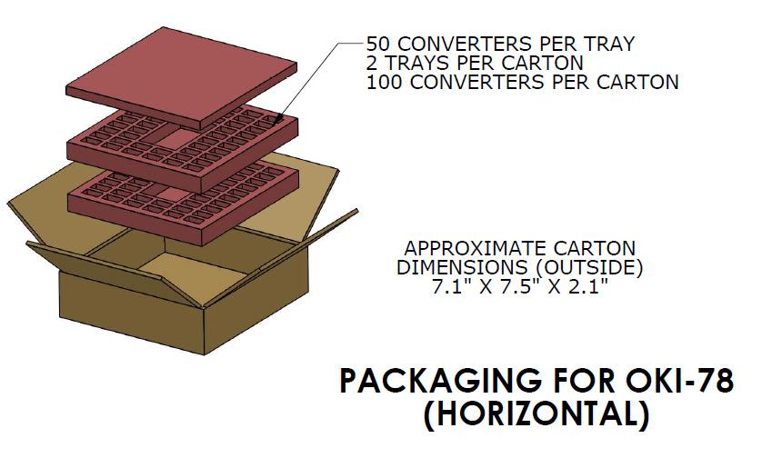
18 PACKAGING INFORMATION MDC_OKI-78SR-W36.C05 Page 18 of 20
19 TECHNICAL NOTES Input Fusing Certain applications and/or safety agencies may require fuses at the inputs of power conversion components. Fuses should also be used when there is the possibility of sustained input voltage reversal which is not current-limited. For greatest safety, we recommend a fast blow fuse installed in the ungrounded input supply line. The installer must observe all relevant safety standards and regulations. For safety agency approvals, install the converter in compliance with the end-user safety standard. TO OSCILLOSCOPE + VIN + CBUS LBUS CURRENT PROBE CIN +VIN -VIN Recommended Input Filtering The user must assure that the input source has low AC impedance to provide dynamic stability and that the input supply has little or no inductive content, including long distributed wiring to a remote power supply. The converter will operate with no additional external capacitance if these conditions are met. CIN = 2 x 100μF, ESR < 100kHz CBUS = 1000μF, ESR < 100kHz LBUS = 1μH Figure 3 Measuring Input Ripple Current For best performance, we recommend installing a low-esr capacitor immediately adjacent to the converter s input terminals. The capacitor should be a ceramic type such as the Murata GRM32 series or a polymer type. Initial suggested capacitor values are 10 to 22 μf, rated at twice the expected maximum input voltage. Make sure that the input terminals do not go below the undervoltage shutdown voltage at all times. More input bulk capacitance may be added in parallel (either electrolytic or tantalum) if needed. +VOUT C1 C2 SCOPE RLOAD Recommended Output Filtering The converter will achieve its rated output ripple and noise with no additional external capacitor. However, the user may install more external output capacitance to reduce the ripple even further or for improved dynamic response. Again, use low-esr ceramic (Murata GRM32 series) or polymer capacitors. Initial values of 10 to 47 μf may be tried, either single or multiple capacitors in parallel. Mount these close to the converter. Measure the output ripple under your load conditions. Use only as much capacitance as required to achieve your ripple and noise objectives. Excessive capacitance can make step load recovery sluggish or possibly introduce instability. Do not exceed the maximum rated output capacitance listed in the specifications. -VOUT C1 = 1μF C2 = 10μF LOAD 2-3 INCHES (51-76mm) FROM MODULE Figure 4. Measuring Output Ripple and Noise (PARD) Input Ripple Current and Output Noise All models in this converter series are tested and specified for input reflected ripple current and output noise using designated external input/output components, circuits and layout as shown in the following figures. The Cbus and Lbus components simulate a typical DC voltage bus. Please note that the values of Cin, Lbus and Cbus will vary according to the specific converter model. MDC_OKI-78SR-W36.C05 Page 19 of 20
20 Minimum Output Loading Requirements All models regulate within specification and are stable under no load to full load conditions. Operation under no load might however slightly increase output ripple and noise. Temperature Derating Curves The graphs in this data sheet illustrate typical operation under a variety of conditions. The Derating curves show the maximum continuous ambient air temperature and decreasing maximum output current which is acceptable under increasing forced airflow measured in Linear Feet per Minute ( LFM ). Note that these are AVERAGE measurements. The converter will accept brief increases in current or reduced airflow as long as the average is not exceeded. Note that the temperatures are of the ambient airflow, not the converter itself which is obviously running at higher temperature than the outside air. Also note that natural convection is defined as very flow rates which are not using fan-forced airflow. Depending on the application, natural convection is usually about LFM but is not equal to still air (0 LFM). Murata Power Solutions makes Characterization measurements in a closed cycle wind tunnel with calibrated airflow. We use both thermocouples and an infrared camera system to observe thermal performance. As a practical matter, it is quite difficult to insert an anemometer to precisely measure airflow in most applications. Sometimes it is possible to estimate the effective airflow if you thoroughly understand the enclosure geometry, entry/exit orifice areas and the fan flowrate specifications. CAUTION: If you routinely or accidentally exceed these Derating guidelines, the converter may have an unplanned Over Temperature shut down. Also, these graphs are all collected at near Sea Level altitude. Be sure to reduce the derating for higher altitude. Output Fusing The converter is extensively protected against current, voltage and temperature extremes. However your output application circuit may need additional protection. In the extremely unlikely event of output circuit failure, excessive voltage could be applied to your circuit. Consider using an appropriate fuse in series with the output. Output Current Limiting Current limiting inception is defined as the point at which full power falls below the rated tolerance. See the Performance/Functional Specifications. Note particularly that the output current may briefly rise above its rated value in normal operation as long as the average output power is not exceeded. This enhances reliability and continued operation of your application. If the output current is too high, the converter will enter the short circuit condition. Output Short Circuit Condition When a converter is in current-limit mode, the output voltage will drop as the output current demand increases. If the output voltage drops too low (approximately 98% of nominal output voltage for most models), the bias voltage may shut down the PWM controller. Following a time-out period, the PWM will restart, causing the output voltage to begin rising to its appropriate value. If the short-circuit condition persists, another shutdown cycle will initiate. This rapid on/off cycling is called hiccup mode. The hiccup cycling reduces the average output current, thereby preventing excessive internal temperatures and/or component damage. The hiccup system differs from older latching short circuit systems because you do not have to power down the converter to make it restart. The system will automatically restore operation as soon as the short circuit condition is removed. Soldering Guidelines Murata Power Solutions recommends the specifications below when installing these converters. These specifications vary depending on the solder type. Exceeding these specifications may cause damage to the product. Your production environment may differ; therefore please thoroughly review these guidelines with your process engineers. Wave Solder Operations for through-hole mounted products (THMT) For Sn/Ag/Cu based solders: For Sn/Pb based solders: Maximum Preheat Temperature 115 C. Maximum Preheat Temperature 105 C. Maximum Pot Temperature 270 C. Maximum Pot Temperature 250 C. Maximum Solder Dwell Time 7 seconds Maximum Solder Dwell Time 6 seconds Murata Power Solutions, Inc. 129 Flanders Road, Westborough, MA U.S.A. ISO 9001 and REGISTERED This product is subject to the following operating requirements and the Life and Safety Critical Application Sales Policy: Refer to: Murata Power Solutions, Inc. makes no representation that the use of its products in the circuits described herein, or the use of other technical information contained herein, will not infringe upon existing or future patent rights. The descriptions contained herein do not imply the granting of licenses to make, use, or sell equipment constructed in accordance therewith. Specifications are subject to change without notice Murata Power Solutions, Inc. MDC_OKI-78SR-W36.C05 Page 20 of 20
OKI-78SR Series Fixed Output 1.5 Amp SIP DC/DC Converters
 www.murata-ps.com OKI-78SR Series Typical units FEATURES Ultra wide 7 to 36 VDC input range Fixed Outputs of 3.3 or 5 VDC up to 1.5 Amps Vertical or horizontal SIP-mount, small footprint package No heat
OKI-78SR Series Fixed Output 1.5 Amp SIP DC/DC Converters
 OKI-78SR Series Typical unit FEATURES Ultra wide 7 to 36 VDC input range Fixed Outputs of 3.3 or 5 VDC up to 1.5 Amps Vertical or horizontal SIP-mount, small footprint package No heat sink direct replacement
OKR-T/1.5-W12-C Adjustable Output 1.5-Amp SIP-mount DC/DC Converters
 www.murata-ps.com OKR-T/1.5-W12-C Typical unit FEATURES 600 KHz operation 4.5-14 Vdc input voltage range Programmable output voltage from 0.591-6.0 VDC High power conversion effi ciency at 93% Outstanding
OKX T/3-W5 Series Adjustable 3-Amp SIP Non-Isolated DC/DC Converters
 www.murata-ps.com FEATURES Non-isolated SIP PoL DC/DC power module 2.4-5.5Vdc input voltage range Programmable output voltage from 0.7525-3.366Vdc Under Voltage shutdown (Vin) Drives 1000 μf ceramic capacitive
OKX T/5-W5 Series Adjustable 5-Amp SIP Non-Isolated DC/DC Converters
 www.murata-ps.com OKX T/5-W5 Series FEATURES Non-isolated SIP PoL DC/DC power module 2.4-5.5Vdc input voltage range Programmable output voltage from 0.7525-3.366Vdc Under Voltage shutdown (Vin) Drives
OKR-T/30-W12-C Adjustable Output 30-Amp SIP-mount DC-DC Converters
 www.murata-ps.com OKR-T/30-W12-C Typical unit FEATURES 700 KHz operation 5.5-13.8 Vdc input voltage range Programmable output voltage from 0.591-6.0 VDC High power conversion effi ciency at 95% Outstanding
OKR-T/20-W12-C Adjustable Output 20-Amp SIP-mount DC-DC Converters
 www.murata-ps.com OKR-T/20-W12-C Typical unit FEATURES 670 KHz operation 6.0-13.8 Vdc input voltage range Programmable output voltage from 0.591-5.0 VDC High power conversion effi ciency at 94% Outstanding
UWE W Series Wide Input, Isolated Eighth-Brick DC-DC Converters
 www.murata-ps.com UWE-100-120W Series The UWE Series "Eighth-Brick" DC-DC Converters are high-current isolated power modules designed for use in high-density system boards. Typical units FEATURES Industry-standard
PRODUCT OVERVIEW. Isolation Barrier Switching. +Sense (7) External DC Power Source. Filters. Current Sense. Reference and Error Amplifier
 External DC Power Source. Filters. Current Sense. Reference and Error Amplifier") www.murata-ps.com Typical units FEATURES Industry standard DOSA "Sixteenth-brick" format and pinout with surface mount option 36-75 Volts DC input range, 3.3, 5, 6.5, and 12 Vdc outputs. 2250 Volt Basic
www.murata-ps.com Typical units FEATURES Industry standard DOSA "Sixteenth-brick" format and pinout with surface mount option 36-75 Volts DC input range, 3.3, 5, 6.5, and 12 Vdc outputs. 2250 Volt Basic
IRS-Q12 Series Encapsulated Sixteenth-Brick DOSA-Compatible, Wide Input Isolated DC-DC Converters
 Output Voltage (Vdc) Output Current (A) 3.3 15.0 9 to 36 5 10.0 9 to 36 12 4.5 9 to 36 15 3.3 9 to 36 24 2.0 9 to 36 Input Voltage Range (Vdc) Typical unit Optimized for harsh environments in industrial/railway
DESCRIPTION. Inhibit On/Off 4. Figure 1. Connection Diagram
 DESCRIPTION The MPDTH series non-isolated DC/DC power modules are small in size but big on performance and flexibility. Their high output current, compact footprint and industry-leading features offer
MPDTH***60 Series Adjustable Non-isolated 10-Amp POLA DC/DC Converters
 www.murata-ps.com MPDTH*** Series DESCRIPTION The MPDTH series non-isolated DC/DC power modules are small in size but big on performance and fl exibility. Their high output current, compact footprint and
OKX T/10 & T/16-W5 Series Adjustable DOSA 10/16-Amp SIP DC/DC Converters
 OKX T/10 & T/16-W5 Series FEATURES Non-isolated SIP POL DC/DC power module 2.4-5.5Vdc input voltage range Typical unit Programmable output voltage from 0.25-3.63Vdc 10 Amp (T/10) or 16 Amp (T/16) output
UEE Series.
 www.murata-ps.com Output (V) Current (A) Nominal Input (V) 3.3 15 48 3.3 25 48 3.3 30 48 5 10 48 For efficient, fully isolated DC power in the smallest space, the UEE open frame DC-DC converter series
OKX T/10 & T/16-W5 Series Adjustable DOSA 10/16-Amp SIP DC/DC Converters
 www.murata-ps.com FEATURES Non-isolated SIP POL DC/DC power module 2.4-5.5Vdc input voltage range Programmable output voltage from 0.25-3.63Vdc 10 Amp (T/10) or 16 Amp (T/16) output current models Drives
OKI-T/3-W32 Series Adjustable Output 3-Amp DOSA-SMT DC/DC Converters
 OKI-T/3-W32 Series Typical unit PRODUCT OVERVIEW The OKI-T/3 series are non-isolated Point-of- Load (POL) DC/DC power converters for embedded applications. The module is fully compatible with Distributed-power
MPDTH***10 Series Adjustable Non-isolated 12/15-Amp POLA DC/DC Converters
 www.murata-ps.com MPDTH***10 Series DESCRIPTION The MPDTH series non-isolated DC/DC power modules are small in size but big on performance and fl exibility. Their high output current, compact footprint
DESCRIPTION. Inhibit On/Off 3. Margin Down. Margin Up. Figure 1. Connection Diagram
 DESCRIPTION The MPDTH series non-isolated DC/DC power modules are small in size but big on performance and flexibility. Their high output current, compact footprint and industry-leading features offer
ULS 60-Watt Series. Sixteenth-brick DOSA-Compatible, Isolated DC/DC Converters YYWW PART NUMBER STRUCTURE
 www.murata-ps.com FEATURES Small footprint DC/DC converter, ideal for high current applications Tiny 0.9" x 1.3" x 0.40" open frame package Industry standard DOSA "brick" format and pinout with surface
OKR-T/3-W12 Series Adjustable Output 3-Amp SIP-mount DC/DC Converters
 Typical unit FEATURES Vertical SIP-mount small footprint package Output from 0.591 to 6 VDC Ultra wide 4.5 to 13.8 VDC input range Outstanding thermal performance and derating Output overcurrent, short
SIL20C SERIES. Single Output. SIL20C Series 20 A DC-DC Converter C Class Non-Isolated
 SIL20C SERIES Single Output Wide output voltage trim (0.9 Vdc to 5.0 Vdc, 20 A max.) Power good output signal (open collector) Input undervoltage lockout Current sink capability for termination applications
SMT20C SERIES. Single Output TÜV. SMT20C Series 20 A DC-DC Converter C Class Non-Isolated
 SMT20C SERIES Single Output Wide output voltage trim (0.9 Vdc to 5.0 Vdc, 20 A max.) Power good output signal (open collector) Input undervoltage lockout Current sink capability for termination applications
0RCY-F0S10x Isolated DC-DC Convert
 0RCY-F0S10x Isolated DC-DC Convert The 0RCY-F0S10x is an isolated DC/DC converter that operate from a nominal 50 V/54 V source. This converter is intended to provide isolation and step down to generate
OKX T/10 & T/16-D12 Series Adjustable DOSA 10/16-Amp SIP DC/DC Converters
 OKX T/10 & T/16-D12 Series FEATURES Non-isolated SIP POL DC/DC power module 8.3-14Vdc input voltage range Typical unit Programmable output voltage from 0.7525-5.5Vdc 10 Amp (T/10) or 16 Amp (T/16) output
OKL2-T/20-W5 Series Programmable Output 20-Amp ilga SMT PoL DC-DC Converter Series
 www.murata-ps.com Typical unit FEATURES ilga inspectable Land Grid Array.4-5.5Vdc input voltage range Programmable output voltage from.6-3.63vdc Drives 1μF ceramic capacitive loads High power conversion
OKL-T/6-W5 Series. Programmable Output 6-Amp ilga SMT PoLs. FEATURES PRODUCT OVERVIEW
 www.murata-ps.com OKL-T/-W Series Typical unit FEATURES.-.Vdc input voltage range Programmable output voltage from.-.vdc High power conversion effi ciency at 9.% Inspectable Land Grid Array Drives up to
OKY-T/10 & T/16-W5 Series Programmable DOSA-SMT 10/16-Amp DC/DC Converters
 www.murata-ps.com FEATURES Wide 2.4-5.5 VDC input range Non-isolated output adjustable from 0.7525 to 3.63 Volts up to 16 Amps DOSA-compatible SMT package Drives 1000 μf ceramic capacitive loads Optional
HPQ-3.3/50-D48 Series
 www.murata-ps.com HPQ-3.3/50-D48 Series FEATURES 3.3 Volts DC fi xed output up to 50 Amps Industry standard quarter brick 2.3" x 1.45" x 0.40" open frame package Wide range 36 to 75 Vdc input voltages
LSM2-T/30-D12 Series. DOSA-SMT, 30A POL DC/DC Converters. Technical enquiries tel:
 LSM2-T/30-D12 Series Typical unit FEATURES Non-isolated Point-of-Load (POL) converter, ideal for distributed bus applications Optimized for CPUs, DSPs and programmable logic - FPGAs, ASICs 30 Amps maximum
YNV12T05 DC-DC Converter Data Sheet VDC Input; VDC 5 A
 The Products: Y-Series Applications Intermediate Bus Architectures Telecommunications Data communications Distributed Power Architectures Servers, workstations Benefits High efficiency no heat sink required
OKX T/10 & T/16-D12 Series Adjustable DOSA 10/16-Amp SIP DC/DC Converters
 www.murata-ps.com OKX T/10 & T/16-D12 Series FEATURES Non-isolated SIP POL DC/DC power module 8.3-14Vdc input voltage range Programmable output voltage from 0.7525-5.5Vdc 10 Amp (T/10) or 16 Amp (T/16)
OKL2-T/20-W12 Series Programmable Output 20-Amp ilga SMT PoL DC-DC Converter Series
 www.murata-ps.com Typical unit FEATURES ilga inspectable Land Grid Array 4.5-14Vdc input voltage range Programmable output voltage from.9-5.5vdc Drives μf ceramic capacitive loads High power conversion
Networking Computers and Peripherals Telecommunications
 The 0RCY-60U12x is part of the isolated DC/DC converters that operate from a wide input range (18 VDC - 75 VDC) and can cover both 24 Vin and 48 Vin input range. These units will provide up to 84 W of
(typ.) (Range) Parameter Model Min. Typ. Max. Unit
 (Range) Parameter Model Min. Typ. Max. Unit") FEATURES Smallest Encapsulated 20W! Package Size 1.0 x1.0 x0.4 Ultra-wide 4:1 Input Range Very high Efficiency up to % Operating Temp. Range - C to +85 C Output Voltage Trimmable I/O-isolation Voltage
FEATURES Smallest Encapsulated 20W! Package Size 1.0 x1.0 x0.4 Ultra-wide 4:1 Input Range Very high Efficiency up to % Operating Temp. Range - C to +85 C Output Voltage Trimmable I/O-isolation Voltage
MIW3000 Series EMI. 5-6W, Wide Input Range DIP, Single & Dual Output DC/DC Converters MINMAX. Block Diagram. Key Features
 -6W, Wide Input Range DIP, Single & DC/DC s Key Features Efficiency up to 10 Isolation MTBF > 1,000,000 Hours 2:1 Wide Input Range UL19 Safety Approval Complies with EN22 Class A Temperature Performance
Line and Load Regulation ±1%/±1%
 www.murata-ps.com 11-13.2Vin, 54.2V/4.44A Single Output, High Efficiency SIP Converter ORDERING GUIDE SUMMARY Model Vout Range Iout Range Vin Range Ripple/Noise Efficiency 54.2V 0-4.44A 11-13.2V 500mVp-p
Typical unit PRODUCT OVERVIEW
 www.murata-ps.com OKL-T/-W5 Series Typical unit FEATURES ilga inspectable Land Grid Array.4-5.5Vdc input voltage range Programmable output voltage from 0.6-.6Vdc Drives 00 µf ceramic capacitive loads High
OKY-T/10 & T/16-D12 Series Programmable DOSA-SMT 10/16-Amp DC/DC Converters
 www.murata-ps.com FEATURES Wide 8.3-14 VDC input range Non-isolated output adjustable from 0.25 to 5.5 Volts up to 16 Amps DOSA-compatible SMT package Optional sequence/tracking operation Outstanding thermal
PAQ Series. Up to 150W 29.8V Nom Output Quarter-Brick Isolated DC-DC Converter with 2:1 Wide Input Range.
 www.murata-ps.com PAQ Series KEY PRODUCT FEATURES : Input Voltage Range (V 7V) Trimmable.8 (-%) to.78 (%) Volts output (9.8V, nom) Up to W output power @ - 7Vin Effi ciency = 9.% (typ) Industry standard
Efficiency (typ.) (Range) Load. Output Current Input Current Reflected Ripple
 (Range) Load. Output Current Input Current Reflected Ripple") FEATURES Highest Power Density 1" x 1" x 0.4" Shielded Metal Package Ultra Wide 4:1 Input Range Excellent Efficiency up to % Operating Temp. Range - C to + C Optional Heatsink I/O-isolation Voltage 10VDC
FEATURES Highest Power Density 1" x 1" x 0.4" Shielded Metal Package Ultra Wide 4:1 Input Range Excellent Efficiency up to % Operating Temp. Range - C to + C Optional Heatsink I/O-isolation Voltage 10VDC
IRS Series. Encapsulated Sixteenth-Brick DOSA-Compatible, Wide Input Isolated DC-DC Converters. FEATURES
 www.murata-ps.com Typical units Output Voltage (V) Output Current (A) Input Voltage (V) 3.3 1 18-7 10 18-7 12 4. 18-7 Optimized for harsh environments in industrial/railway applications, the IRS DC-DC
S24SP series 60W Single Output DC/DC Converter
 Model List Model Number Input Voltage (Range) Output Voltage Output Current Input Current (typ input voltage) Load Regulation Maxcapacitive Load (Cap ESR>=1mohm;Full Efficiency (typ.) load;5%overshoot
200 WATT TH SERIES DC/DC CONVERTERS
 Features 4:1 Input voltage range High power density Small size 2.4 x 2.28 x 0.65 Efficiency up to 90 Excellent thermal performance with metal case Pulse-by-pulse current limiting Over-temperature protection
MYSGK02506BRSR DC-DC converter
 Typical unit FEATURES Input Voltage range 13.5 to 42Vdc (Absolute maximum input voltage:50vdc) Settable output voltage range 5 to 25Vdc Up to 6A of output current Ultra small surface mount package 14.7
Distributing Tomorrow s Technologies For Today s Designs Toll-Free:
 3W, Wide Input Range DIP, Single & DC/DC s Key Features Efficiency up to 82 Isolation MTBF > 1,000,000 Hours 2:1 Wide Input Range Low Cost Complies with EN022 Class A Temperature Performance -2 to +71
ULS 100-Watt Series Sixteenth-brick DOSA-Compatible, Isolated DC-DC Converters
 www.murata-ps.com Typical units FEATURES Industry standard DOSA "Sixteenth-brick" format and pinout with surface mount option 36-75 Volts DC input range, 3.3, 5 and 12 Vdc outputs. 2250 Volt Basic input/output
S24SE/S24DE series 30W Single/Dual Output DC/DC Converter
 FEATURES Efficiency up to 89% Wide input range, 9V-36V Package with Industry Standard Pinout Package Dimension: 25.4 x25.4 x10.2mm (1.0 x1.0 x0.40 )(No HSK) Over voltage protection, hiccup mode Over current
MYSGK1R830 Series. Mono Block Type Small & High Power Density 30A DC-DC Converter Series PRODUCT OVERVIEW
 PRODUCT OVERVIEW Typical unit FEATURES Settable output voltage from 0.7 to 1.8Vdc Up to 30A of output current Quick response to load change Ultra small surface mount package 14.0 x 11.0 x 8.3mm High efficiency
UWS Series Sixteenth-brick DOSA-Compatible, Wide Input Isolated DC-DC
 www.murata-ps.com Wide Input Isolated DC-DC Converters FEATURES High effi ciency synchronous fl yback topology 18-75 Volts DC wide input range with 3.3, 5 and 12 Volts for Output voltage Up to 54 Watts
SRPE-50E1A0 Non-Isolated DC-DC Converter
 SRPE-50E1A0 Non-Isolated DC-DC Converter The Bel SRPE-50E1A0 is part of the non-isolated dc to dc converter Power Module series. The modules use a Vertical SMT package. These converters are available in
DRQ-11.4/88-L48NB-C. Regulated Quarter-Brick, 986W Isolated DC-DC Converter
 www.murata-ps.com DRQ-11.4/88-L48NB-C Output (V) Current (A) Nominal Input (V) 11.2 88 48 Optimized for distributed power Regulated Intermediate Bus Architectures (RIBA), the DRQ DC-DC converter series
Distributing Tomorrow s Technologies For Today s Designs Toll-Free:
 2W, Wide Input Range DIP, Single & DC/DC s Key Features Efficiency up to 81 Isolation MTBF > 1,000,000 Hours 2:1 Wide Input Range CSA1 Safety Approval Low Ripple and Noise Short Circuit Protection Complies
(DOSA) VDC, 5.5 A.
 VDC, 5.5 A.") Features Industry-standard pinout Output: 15 V at 5.5 A, 82.5W max. No minimum load required Low height - 0.374 (9.5mm) max. Basic Insulation Withstands 100 V input transients Fixed-frequency operation
Features Industry-standard pinout Output: 15 V at 5.5 A, 82.5W max. No minimum load required Low height - 0.374 (9.5mm) max. Basic Insulation Withstands 100 V input transients Fixed-frequency operation
The 0RQB-C5U54x is an isolated DC-DC converter that operates from a nominal 24 VDC, 48 VDC source.
 The 0RQB-C5U54x is an isolated DC-DC converter that operates from a nominal 24 VDC, 48 VDC source. This unit will provide up to 162 W of output power from a nominal 24 VDC, 48 VDC input. This unit is designed
OVP 2:1. Wide Range. Protection
 10W, Wide Input Range DIP, Single & Dual Output DC/DC s Key Features High Efficiency up to 88 10 Isolation MTBF > 1,000,000 Hours 2:1 Wide Input Range CSA9-1 Safety Approval Complies with EN522 Class A
S24SE/S24DE series 15W Single/Dual Output DC/DC Converter
 FEATURES Efficiency up to 89% Wide input range, 9V-36V Package with Industry Standard Pinout Package Dimension: 25.4 x25.4 x10.2mm (1.0 x1.0 x0.40 )(No HSK) Over voltage protection, hiccup mode Over current
MYMGK1R820 Series. Mono Block Type Small & High Power Density 20A DC-DC Converter Series PRODUCT OVERVIEW
 Typical unit FEATURES Programmable output voltage from 0.7 to 1.8Vdc Up to 20A of output current Quick response to load change Ultra small surface mount package 10.5 x 9.0 x 5.6mm High efficiency of 89.2%
IRS Series. Encapsulated Sixteenth-Brick DOSA-Compatible, Wide Input Isolated DC-DC Converters. FEATURES
 www.murata-ps.com Typical units Output Voltage (V) Output Current (A) Input Voltage (V) 3.3 1 18-7 10 18-7 12 4. 18-7 Optimized for harsh environments in industrial/railway applications, the IRS DC-DC
Q54SJ W DC/DC Power Modules FEATURES. Q54SJ12058, 700W Quarter Brick DC/DC Power Modules: 40~60Vin, 12.2V/ 57.4A out OPTIONS APPLICATIONS
 Q54SJ12058 700W DC/DC Power Modules FEATURES High efficiency: 96.4% @ 12.2V/57.4A out size : 57.9 x 36.8 x 12.0mm (2.28 x1.45 x0.47 ) (open frame) 57.9 x 36.8 x 13.4mm (2.28 x1.45 x0.53 ) (with base plate)
Efficiency (typ.) (Range) Max. Load VDC VDC ma ma ma(typ.) ma(typ.) μf % MJWI10-24S033
 (Range) Max. Load VDC VDC ma ma ma(typ.) ma(typ.) μf % MJWI10-24S033") FEATURES Package Size 1.0 x1.0 x0.4 Ultrawide 4:1 Input Range High Efficiency up to 87% Operating Temp. Range 40 C to 80 C I/Oisolation Voltage 1500VDC Remote On/Off Control Input Filter complies to EN55022,Class
FEATURES Package Size 1.0 x1.0 x0.4 Ultrawide 4:1 Input Range High Efficiency up to 87% Operating Temp. Range 40 C to 80 C I/Oisolation Voltage 1500VDC Remote On/Off Control Input Filter complies to EN55022,Class
0RQB-X3S11B(F) Isolated DC-DC Converter
 Isolated DC-DC Converter") 0RQB-X3S11B(F) Isolated DC-DC Converter The 0RQB-X3S11B(F) is an isolated DC/DC converter that operates from a nominal 50/54 Vdc source. This converter is intended to provide isolation and step down to
0RQB-X3S11B(F) Isolated DC-DC Converter The 0RQB-X3S11B(F) is an isolated DC/DC converter that operates from a nominal 50/54 Vdc source. This converter is intended to provide isolation and step down to
S24SP12004 series 40W Single Output DC/DC Converter
 FEATURES Efficiency up to 92.8% Wide input range, 9V-36V Package with Industry Standard Pinout Package Dimension: Without heat sink 5.8 x25.4 x1.5mm (2. x1. x.41 ) With heat sink 5.8 x25.4 x17.5mm (2.
S24SP05012 series 60W Single Output DC/DC Converter
 Model List Model Number S24SP05012 Input Voltage (Range) Output Voltage Output Current Input Current (typ input voltage) Load Regulation Maxcapacitive Load (Cap ESR>=10mohm;Full Efficiency load;5%overshoot
S24SP24003 series 60W Single Output DC/DC Converter
 FEATURES Efficiency up to 93% Wide input range, 9V-36V Package with Industry Standard Pinout Package Dimension: Without heat sink 5.8 x25.4 x1.5mm (2. x1. x.41 ) With heat sink 5.8 x25.4 x17.5mm (2. x1.
TBD. Delphi E36SR Series DC/DC Power Modules: 18~60 in, 12V/4A out, 48W FEATURES OPTIONS APPLICATIONS
 FEATURES High efficiency: 91% @ 12V/4A Size: 58.4x22.8x8.73mm (2.30 x0.90 x0.34 ) Standard footprint Industry standard pin out TBD Fixed frequency operation Input UVLO, Output OCP, OVP, OTP 1500V isolation
UEI30 Series 30W Isolated Wide-Range DC-DC Converters
 www.murata-ps.com UEI3 Series Featuring a full 3 Watt output in 1.8 square inches of board area, the UEI series isolated DC/DC converter family offers efficient regulated DC power for printed circuit board
PAH-28 Vout, 350-Watt Series
 www.murata-ps.com PAH- Vout, 35-Watt Series Output (V) Current (A) Input Voltage (V).5 1-3 or 3-75 Typical unit FEATURES Vout @.5A (35W) Trimmable 1. Vout to 3. Vout @ 35W with Vin = 1-3V (D) or 3-75V
PRELIMINARY PAQ Series
 www.murata-ps.com PRELIMINARY KEY PRODUCT FEATURES : Input Voltage Range (V 7V, D8) Trimmable.8 (-%) to.78 (%) Volts output (9.8V, nom) Up to W output power @ - 7Vin Effi ciency = 9.% (typ) Industry standard
Cool Power Technologies
 Cool Power Technologies Sixteenth-Brick Isolated DC/DC Converter Features Industry-standard pinout Wide input voltage range: 36 75Vin Output: 3.3 V at 12 A, 40W max. No minimum load required Low height
SELECTION GUIDE. Nominal Input Voltage Output Voltage. Output Current
 www.murata-ps.com SELECTION GUIDE Order Code Nominal Input Voltage Output Current Input Current at Rated Load Load Regulation (Typ) Load Regulation (Max) Ripple & Noise (Typ) 1 Ripple & Noise (Max) 1 Efficiency
360 WATT MTW SERIES DC/DC CONVERTERS
 Description The 4:1 Input Voltage 360 Watt Single MTW DC/DC converter provides a precisely regulated dc output. The output voltage is fully isolated from the input, allowing the output to be positive or
MER1 Series 1kVDC Isolated 1W Single Output DC/DC Converters
 www.murata-ps.com MER1 Series SELECTION GUIDE Order Code Nominal Input Voltage Output Voltage Output Current Input Current at Rated Load Load Regulation (Typ) Load Regulation (Max) Ripple & Noise (Typ)
S24SE/S24DE series 30W Single/Dual Output DC/DC Converter
 Model List Model Number Input Voltage Output Voltage Output Current Input Current (typ input voltage) (Range) Max. Min. @Max. Load @No Load Load Regulation Maxcapacitive Efficiency Load (typ.) @Max. Load
OKL-T/6-W12 Series Programmable Output 6-Amp ilga SMT PoLs
 www.murata-ps.com Typical unit FEATURES ilga inspectable Land Grid Array.5-1Vdc input voltage range Programmable output voltage from.591-5.5vdc Drives up to 3 μf ceramic capacitive loads High power conversion
Typical unit. Reference and Error Amplifier
 www.murata-ps.com RBE-1/-D Series Eighth-Brick -Watt Isolated DC/DC Converters Typical unit FEATURES Watts total output power, fixed1 VDC @ A 9.5% ultra-high efficiency at full load with regulation 3 to
500 WATT MXW SERIES DC/DC CONVERTERS
 4:1 Input voltage range High power density Small size 2.4 x 2.5 x 0.52 Efficiency up to 95.7% Excellent thermal performance with metal case Over-Current and Short Circuit Protection Over-Temperature protection
SELECTION GUIDE - SINGLE OUTPUT 1. Nominal Input Voltage Output Voltage
 www.murata-ps.com MEV1 Series SELECTION GUIDE - SINGLE OUTPUT 1 Order Code Nominal Input Voltage Output Voltage Output Current Input Current at Rated Load Load Regulation (Typ) Load Regulation (Max) Ripple
NMG Series Isolated 2W Single Output DC/DC Converters
 www.murata-ps.com NMG Series SELECTION GUIDE FEATURES UL 69 recognised Efficiency from 8% Wide temperature performance at full 2 Watt load, 4 C to 85 C Industry standard pinout 1kVDC isolation Hi Pot Test
CLP0112 Open Frame Power Supply Vac input; 12Vdc output; 150W Output Power
 Applications Telecommunications equipment Embedded Computing Storage Systems Industrial equipment Features Compact size 50.8 mm x 101.6 mm x 36.1 mm (2 in x 4 in x 1.4 in) with density of 13.4W/in 3 Universal
SELECTION GUIDE. Nominal Input Voltage Output Voltage. Output Current
 www.murata-ps.com CRV2 Series SELECTION GUIDE Order Code Nominal Input Voltage Output Voltage Output Current Input Current at Rated Load Load Regulation (Typ) Load Regulation (Max) Ripple & Noise (Typ)
MAX. OUTPUT POWER 24/48/72/96/110 VDC 5 VDC 6 A 30 W 82% 0RQB-30Y05L. 0 R QB - 30 Y 05 L y. Output Power. Input Range
 The 0RQB-30Y05L is an isolated DC/DC converter providing 30 W of output power from a wide input range (24 V, 48 V, 72 V, 96 V, 110 V typical). Standard features include remote on/off, input under-voltage
S020_084-S V input, 1.2 to 5.0V adjustable output, 20A or 55W
 S2_84-S2- Features High output 2A up to 55W max 12V +5/-1% input Load Regulation ±.5% Factory set to 1.2V output with output trim up to 5.V High Efficiency to 93% Power Good and Enable Short Circuit protection
DC/DC Converter 9 to 36Vdc and 18 to 75Vdc input voltage, 20 Watt Output Power; 3.3 to 15Vdc Single Output and ±12Vdc to ±15Vdc Dual Output
 THN 20WI Series Application Note DC/DC Converter 9 to 36Vdc and 18 to 75Vdc input voltage, 20 Watt Output Power; 3.3 to 15Vdc Single Output and ±12Vdc to ±15Vdc Dual Output Pending Applications Wireless
S016_084-S V Input, V Adjustable Output, 16A or 45W
 S016_084-S016-00 Features Output Current up to 16A or 45W max 12V +5/-10% input Load Regulation ±0.5% Factory set to 1.2V Output with Output Trim up to 5.0V High Efficiency to 90% Back Bias Protection
150 WATT QSW DC/DC CONVERTERS
 Description The 4:1 Input Voltage 150 Watt Single QSW DC/DC converter provides a precisely regulated dc output. The output voltage is fully isolated from the input, allowing the output to be positive or
UEE 150W Series Isolated, High-Density, Eighth-Brick DOSA Low Profi le DC-DC Converters
 www.murata-ps.com Typical units FEATURES Synchronous rectifi cation yields high effi ciency over 9% 3 to 75 Vdc input range (V nominal) Outstanding thermal performance and derating Low profi le." height
Asia-Pacific Europe, Middle East North America Bel Power Solutions, Inc. BCD.
 The QmaXTM Series of high current single output dc-dc converters set new standards for thermal performance and power density in the quarter-brick package. The 45 A QM48 converters of the QmaXTM Series
Single negative output
 SIL25C SERIES Single negative output Trim range (-4.5 Vdc to -5.5 Vdc) High power density design means reduced board space requirement Remote sense Power good output signal (open collector) Operating ambient
MER1 Series 1kVDC Isolated 1W Single Output DC-DC Converters
 www.murata-ps.com MER1 Series SELECTION GUIDE Order Code Nominal Input Voltage Output Voltage Output Current Input Current at Rated Load Load Regulation (Typ) Load Regulation (Max) Ripple & Noise (Typ)
Efficiency (typ.) (Range) Load VDC VDC ma ma(typ.) ma(typ.) μf % MCWI05-12S
 (Range) Load VDC VDC ma ma(typ.) ma(typ.) μf % MCWI05-12S") FEATURES Smallest Encapsulated 5W Ultracompact SIP8 Package Ultrawide 4 : 1 Input Voltage Range Fully Regulated Output Voltage I/O Isolation 1500 VDC Operating Ambient Temp. Range40 to 75 No Min. Requirement
FEATURES Smallest Encapsulated 5W Ultracompact SIP8 Package Ultrawide 4 : 1 Input Voltage Range Fully Regulated Output Voltage I/O Isolation 1500 VDC Operating Ambient Temp. Range40 to 75 No Min. Requirement
Naos Raptor 6A: Non-Isolated DC-DC Power Modules 4.5Vdc 14Vdc input; 0.59Vdc to 6Vdc Output; 6A Output Current
 Naos Raptor 6A: Non-Isolated DC-DC Power Modules 4.5Vdc 14Vdc input; 0.59Vdc to 6Vdc Output; 6A Output Current RoHS Compliant Applications Distributed power architectures Intermediate bus voltage applications
PXD30-xxWS-xx-Single Output DC/DC Converters
 PXD30-xxWS-xx-Single Output DC/DC Converters 9 to 36 Vdc and 18 to 75 Vdc input, 1.5 to 15 Vdc Single Output, 30W Applications Wireless Network Telecom / Datacom Industry Control System Measurement Semiconductor
OKL-T/3-W12 Series Programmable Output 3-Amp ilga SMT PoLs
 www.murata-ps.com OKL-T/3-W12 Series Typical unit FEATURES ilga inspectable Land Grid Array 4.5-14Vdc input voltage range Programmable output voltage from 0.591-5.5Vdc Drives up to 200 μf ceramic capacitive
OKX T/10 & T/16-D12 Series Adjustable DOSA 10/16-Amp SIP DC/DC Converters
 OKX T/ & T/16-D12 Series FEATURES Non-isolated SIP POL DC/DC power module 8.3-14Vdc input voltage range Programmable output voltage from 0.75-5.5Vdc Amp (T/) or 16 Amp (T/16) output current models Drives
Delphi Series S48SP, 35W 1x1 Brick DC/DC Power Modules: 48V in, 5V/7A out
 FEATURES High efficiency: 9% @5V/7A Industry standard 1x2 pin out Size: 33.x24.4x8.55mm (1.3 x.96 x.34 ) SMD and Through-hole versions Fixed frequency operation 2:1 input voltage range Input UVLO, OVP
PAE Series. Up to 100W 29.8V Nom Output Eighth-Brick Isolated DC-DC Converter with 2:1 Wide Input Range.
 www.murata-ps.com PAE Series KEY PRODUCT FEATURES : Input Voltage Range (6V 75V) Trimmable.8 (-0%) to.78 (0%) Volts output (9.8V, nom) Up to 00W output power @ 6-75Vin Effi ciency = 9.5% (typ) Industry
Delphi Series S36SA, 25W Family DC/DC Power Modules: 18Vin to 60Vin, 3.3V/8A out
 FEATURES High efficiency: 88.5% @ 3.3V/8A Size: 47.20mmx29.5mmx8.15mm (1.86 x1.16 x0.32 ) Wide input voltage range: 18V~60V Standard footprint Surface mountable Industry standard pin out Fixed frequency
PARAMETER CONDITIONS / DESCRIPTION MIN TYP MAX UNITS. Input Voltage Continuous 0 80 VDC. Operating Ambient Temperature C
 The QME48T40 DC-DC Series of converters provide outstanding thermal performance in high temperature environments. This performance is accomplished through the use of patented/patent-pending circuits, packaging,
PXD10-Single Output DC/DC Converter
 PXD10-Single Output DC/DC Converter 9 to 18 Vdc, 18 to 36 Vdc and 36 to 75 Vdc input, 3.3 to 15 Vdc Single Output, 10W Features Single output current up to 2A 10 watts maximum output power 2:1 wide input
Delphi Series Q48SK, Quarter Brick Family DC/DC Power Modules: 36~75V in, 12V/18A out, 216W
 FEATURES High efficiency : 94.7% @ 12V/18A Size: 57.9x36.8x11.2mm (2.28 x1.45 x0.44 ) (w/o heat spreader) 57.9*36.8*12.7mm(2.28 *1.45 0.50 ) (with heat spreader) Standard footprint Industry standard pin