Low Level RF Systems
|
|
|
- Robert Bryant
- 6 years ago
- Views:
Transcription
1 Low Level RF Systems Tom Powers Jan (Slides stolen from: Powers LLRF workshop 2011, Plawski LLRF workshop 2013, Power/Hovater LBL light source working group 2012, Powers, HOM workshop 2012.
2 LLRF the Center of the Universe?? Resonance Controls Receiver/Transmitter at Proper Frequency Algorithms & software LLRF Interlocks EPICS software EPICS Interface Signal Processing
3 General Equation for RF Power and Phase P RF = ( β + 1) L 4β R C 2 {( E + I R cosψ ) + ( E tanψ + I R ψ ) } 2 0 C B 0 C sin B ψ Kly 2Q = arctan δf f0 E + L E + I I 0 R C 0 R C cosψ sinψ B B where P Kly = klystron power {W) V C = cavity accelerating voltage {V} R C = (r/q)q L {W/m} = Coupling impedance L = Cavity accelerating length (m) b = cavity coupling tanψ = Tangent of cavity detuning angle ~ 2Q δf L f o ψ Kly = phase of the RF drive voltage I R = resultant beam current f R = resultant phase of beam with respect to accelerating RF field Q L = Loaded-Q of the Cavity δf = frequency difference between cavity frequency, f 0, and the Generator Frequency
4 Cavity Gradient, RF Voltage and Phase ( ) ( ) ( ) ) / ( 1 ) / ( I itan Q r Q V L Z Q r Q itan E L S L ψ β β ψ = Where ψ is the cavity detune angle and β is the geometrical factor relating to the fundamental power coupler and is constant. ( ) ( ) ( ) ( ) ( ) = B L L B L L S Q r Q I E f f Q i Q r Q I E Q r Q Z L V ψ δ ψ β β sin 2 cos ( ) ( ) + + = B L B L L S Q r Q I E Q r Q I E f f Q Tan ψ ψ δ ψ cos sin f f Q Tan L δ ψ =
5 In terms of I and Q VV RRRR = II + iiii II = ZZ 0 ββ + 1 4ββQQ LL rr/qq EE + II 0QQ LL rr QQ ccccccφφ BB QQ = ZZ 0 ββ + 1 4ββQQ LL rr/qq 2QQ LL δδδδ ff 0 + II 0 QQ LL rr QQ ssssssφφ BB Assumes that EE is at phase equal to zero.
6 General Phase and Gradient Stability Requirements Gradient and phase stability determined during beam physics sensitivity studies. Subject to be different from machine to machine. In general Light Sources phase stability 0.03º to 0.01º rms (60 fs to 18 fs at 1500 MHz) (folks talk about 10 fs for synchronization of final beams to end stations.) Other machines 0.1º to 0.5º is good enough. Gradient stability 0.05% to 0.005% rms Temperature stabilized copper reference distributions systems good to about 100 fs to 500 fs. Fiber distributed laser based systems required for to achieve 10s of fs. For slow drifts remember one bad cable can ruin years of design and implementation.
7 What is Unique About SRF Cavities Normal Conducting Bandwidth of several 10s of khz. Wall losses from a few kw to several hundred kw. Very little reflected power with no beam loading. Except in the highest beam loaded cases, beam loading changes forward power by about 20% or less. Resonance control is typically a water circuit. Microphonics effects minor. Superconducting Bandwidth from 30 Hz to 10 khz Wall losses 1 W to 300 W. All RF power reflected with no beam loading. Beam loading changes forward power by a factor of 4. Resonance control is typically a stepper motor and may include piezo devices. Microphonics can be significant especially for loaded-qs above 5e6.
8 Some of the Necessary Features Loop phase and amplitude control signals available in control room. Tuner control algorithm -- may need fast adaptive controls for pulsed machines or ERLs. Loop gains, bandwidths, etc. control available in the control room. Filter for rejection of the first π mode frequency below the fundamental frequency. First fault buffers. Interface to fast feedback control system. Quench detection Self Excited Loop for cavities with high loaded-q One button turn on of cavities even if they are not properly tuned. Ability to monitor transients waveforms for critical control signals Output Clamp control which limits the drive power under all conditions
9 Other uses of LLRF Drive and seed laser phase control. Using optical detector along with a PZT and pico motor controls. Lock laser fundamental frequency to sub-harmonic of cavity RF. Switch to or augment phase feedback loop with a higher harmonic of laser frequency. Check harmonic content, phase noise, etc. as an on line task. Receiver for beam based phase feedback. As part of a fast feedback system for energy stability. For commissioning the cryomodules and their tuners after installation into the machine. *Caution must be used when choosing frequency for optical and electron beam based detectors in order to avoid interference from high power RF systems.
10 RF IF Band Pass or Low Pass Filter LO IF= cos(w 1 t) cos(w 2 t) IF = Acos(w 1 +w 2 t) + Acos(w 1 -w 2 t) Reject with filter IF = Acos(w 1 +w 2 t) + Acos(w 1 -w 2 t) Where A is the conversion gain of the mixer
11 Analog Approach Phase and Amplitude CEBAF field control chassis 1992 design
12 Analog Approach Phase and Amplitude Mixers are used to (a) down convert the RF signal to the IF frequency and (b) Generate a phase measurement between the 70 MHz reference and the cavity gradient. After applying an offset and gain an error signal is used to control a phase modulator. Note the value of the phase signal is amplitude (i.e. gradient) dependent
13 Analog Approach Phase and Amplitude The amplitude is measured with an ovenized Crystal detector. An error signal is used to drive the control of an amplitude modulator circuit The IF frequency signal which has been phase and amplitude modulated is unconverted by mixing it with a local oscillator signal. Note phase control does not work if the amplitude knob is set to zero.
14 Digital Implementation of LLRF Bachimanchi, et. al. LLRF 2011
15 Digital Implementation of LLRF IF frequency is one of the harmonics that is generated by DAC output Output is up converted to RF frequency and filtered and sent to Klystron. RF signals down converted to IF frequency of 70 MHz. Filtered and buffered for inputs to ADC. ADC clock of 56 MHz is 1/1.25 of IF frequency of 70 MHz for Direct I/Q demodulation. Clock jitter is critical and contributes significantly to the noise floor of the system.
16 Digital Implementation of LLRF FPGA used for signal processing. Can apply specific Filters, Gain control algorithms, Feed Forward, Adaptive feedback and Adaptive feed forward Waveform acquisition First fault detection Imbedded IOC for communication to the control system and resonance control hardware Auxiliary I/O provided for interlocks and future improvements.
.")

17 Digital Implementation of LLRF The local oscillator (LO) frequency (1427 MHz in this example) determines which RF frequency (1497 MHz) actually makes it through the IF filters (70 MHz). Thus if one were to sweep the IF frequency over some range then you would be sweeping through the RF frequencies of the HOM modes. In fact this is the way that the sweep function of a traditional spectrum analyzer operates. As such a modification of this design could be used as a diagnostic tool for HOM measurement or to build a network analyzer function.
18 RF System Configuration for USPAS Cryomodule Test
19 RF System Configuration for USPAS Cryomodule Test Installed Analog LLRF system is left in place including interlocks External directional couplers used to sample the forward and reflected power this introduces about 1 db of additional losses in the forward and reflected power signals as seen in the RFCM Crystal detectors used to provide live waveforms of RF signals Transmitted coupler is built into the RFCM. Using it eliminates errors in calibration factors between the cavity probe signal and the RFCM.
20 RF System Configuration for USPAS Cryomodule Test Boonton 4532 pulsed power meters used to capture RF waveforms. Crystal detectors used to provide the operator with live (uncalibrated) signals on an oscilloscope. Only passive linear circuits used between RF signals and power meters Amplifier used to provide extra signal to the probe crystal detector and to the receiver in the Field Control Chassis
21 RF System Configuration for USPAS Cryomodule Test Modified 12 GeV RF field control chassis used in order to control the RF frequency and pulsed operation. Normal output upconverter and drive circuit (nominal output is 1497 MHz) removed and replaced with a 70 MHz drive circuit. Standard input circuit at 1497 MHz retained. Three modes of operation uses for commissioning. Tone mode which has an output at 1497 MHz with all control loops open. Self Excited Loop mode (SEL) which is a frequency source that tracks the cavity. Pulsed mode which is SEL mode with the ability to pulse the output signal.
22 BASIC VCO-PLL CENTER FREQUENCY ADJUSTMENT RF IF LPF VCO 6 db PHASE ADJUST LOW NOISE OR LIMITING AMPLIFIER LO LOOP AMPLIFIER RF AMPLIFIER Two fundamental ways to drive a cavity. Fixed frequency systems are used in conjunction with resonance controls like motorized tuners when operating fixed frequency systems in accelerators. Variable frequency systems are used to simplify the system or to test cavities which do not have tuners attached. During vertical testing cavity bandwidths on the order of 1 Hz are not uncommon, it would be extremely difficult to maintain the cavity s frequency while testing. At Jefferson Lab we commonly use voltage controlled oscillator based phase locked loops to track the cavity frequency during the test.
23 BASIC VCO-PLL CENTER FREQUENCY ADJUSTMENT RF IF LPF VCO 6 db PHASE ADJUST LOW NOISE OR LIMITING AMPLIFIER LO LOOP AMPLIFIER RF AMPLIFIER Two fundamental ways to drive a cavity. Fixed frequency systems are used in conjunction with resonance controls like motorized tuners when operating fixed frequency systems in accelerators. Variable frequency systems are used to simplify the system or to test cavities which do not have tuners attached. During vertical testing cavity bandwidths on the order of 1 Hz are not uncommon, it would be extremely difficult to maintain the cavity s frequency while testing. We are converting the production systems over to digital LLRF based systems. At Jefferson Lab we commonly use voltage controlled oscillator based phase locked loops to track the cavity frequency during the test.
24 Complete VCO PLL System Layout GAIN POT LOCAL REMOTE SWITCH HI/LO GAIN SWITCH FROM ANALOG I/O PORT (ONE ANALOG, ONE DIGITAL) CONTROL INTERFACE PCB EXTERNAL VCO +12 VDC CENTER FREQUENCY ADJUSTMENT P INPUT T 3 db PIN ATTN 6 db 10 db 30 db 50 db PHASE ADJUST DC BLOCK RF LO IF LPF TRANSMITTED POWER NETWORK CHASSIS 10 db 30 db DC BLOCK 50 P INPUT R P INPUT I P INPUT HOMA P INPUT HOMB PWR METER 50 PWR METER PWR METER 10 db 10 db DUAL CHANNEL PWR METER 10 db 20 db 20 db 10 db 10 db 4 db 6 db 1 db POWER METER INTERFACE CHASSIS DC BLOCK VCO/PLL CHASSIS 6 db AMERICAN MICROWAVE SW A 10 db PIN VECTOR SWITCH MODULATOR FREQUENCY COUNTER VECTOR MODULATOR BUFFER PCB STEP ATTEN RF ON/OFF SWITCH P/O XTAL BUFFER P T, P R, P I, LOOP ERR TO RAD ENABLE P/O XTAL BUFFER PCB LLRF DRIVE FREQ PWR1 PWR2 PWR3 PWR4 GPIB P/O ANALOG I/O DIO COMPUTER INTERFACE P/O ANALOG I/O P/O ANALOG I/O RAD7 RAD8 P7 P8 T. Powers /SRF Workshop 2013 Tutorial
25 BROAD BAND DIGITAL LLRF BASED SYSTEM Work in Progress T. Powers /SRF Workshop 2013 Tutorial
26 BROAD BAND DIGITAL LLRF BASED SYSTEM Switchable gain preamplifer on probe signal very similar to VCO system previously discussed. ZX60-62 amplifiers chosen because of their 24 dbm no damage input specification. Circulator removed in order to keep preamp circuit broad band 50 MHz to 1.8 GHz. Coupler moved to the input circuit in order to better isolate any VSWR missmatches present on the amplifier circuit from input circuit. T. Powers /SRF Workshop 2013 Tutorial
27 BROAD BAND DIGITAL LLRF BASED SYSTEM Power measurement network good from 50 MHz to 1.8 GHz. All couplers are 10 db, 50 MHz to 1.8 GHz devices. Attenuators distributed throughout the circuit in order to insure good VSWR values in power measurement network Variable attenuators included extend the range of linear forward and reflected power signals for observation. T. Powers /SRF Workshop 2013 Tutorial
28 BROAD BAND DIGITAL LLRF BASED SYSTEM Output On/OFF switch for pulsed mode operation. Variable attenuator necessary to insure that the frequency counter is not power starved. It will be conjunction with the LLRF output control to control the amplifier drive signal Low pass filter to reject higher order frequencies out of the mixer. Mixers used for up/down conversion. Attenuator on outputs to provide load in the event cables are disconnected High side local oscillator used to simplify the drive line filter parameters. This source is adjusted to adjusted to bring the cavity frequency to that of the LLRF chassis T. Powers /SRF Workshop 2013 Tutorial
29 INTERLOCKS FOR VERTICAL TESTS During vertical testing medium power amplifiers between 100 W and 500 W are used to drive the cavities. AC PSS HPRF USER SUPPLIED AMPLIFIER AND CIRCULATOR No cavity protection interlocks are used during these tests at Jefferson Lab. Each facility and test should be evaluated individually. Field emission radiation does present a safety hazard. This is mitigated during vertical testing at Jefferson Lab by using one of 6 shielded vertical dewars. High power RF can not be applied to an accelerating structure until the PSS system confirms that the dewar shield lid is closed. Low power, less than 1 W, must be applied to the system in order to calibrate the cables. A switching system shown here was implemented to perform these functions for R&D testing. A similar switching system, along with dewar selection switches and permanently installed cables, was implemented for the production system. SW1 LLRF FROM CONTROL ROOM 1W P5 RF SWITCH UNIT (CONFIGURATION CONTROLLED) FREQ DEPENDENT CIRCULATOR SW2 PSS HPRF P1 PSS P2 P3 P4 LLRF AC P6 CONTROL HIGH POWER RF TO DEWAR T. Powers /SRF Workshop 2013 Tutorial
30 Magnitude and Phase or I/Q Control Algorithms Similar topology for magnitude and phase control and I/Q control. Both use clocking that is effectively 4 times the IF frequency. This can also be done by having the data clock equal to the IF frequency divided by 0.25, 1.25, 2.5, 5.. Both use I/Q de-multiplexing.
31 Magnitude and Phase or I/Q Control Algorithms Synchronous I/Q demodulation
32 V What are I and Q? There are many variations on a theme for cavity field regulation. The two basic parameters that one regulates. Amplitude and Phase. This can be converted to in phase (I) and quadrature (Q). In its simplest form. PEAK ( ω t + ϕ ) = V I cos( ω t) V Q sin( ω t) cos + o PEAK o PEAK A system can be designed such that I an Q can be sampled directly. From a controls standpoint they are orthogonal and the PID loops for each are independent. This can be complicated by the fact that the perturbations to SRF cavity field and phase have different properties and it is desirable to control them with different loop parameters. For multiple cavities you can regulate the vector sum of the I s and Q s for each cavity. Generally not a good idea. o
33 How Do You Directly Sample I and Q I = I p I m Q = Q p - Q m Simple approach Low latency Very little signal processing There are other approaches which are more complex and may be better suited depending on the application. Direct digital down conversion Direct sampling at RF frequency Oversampling
34 Magnitude and Phase Control Algorithm The amount of filtering and decimation is a debatable concept. We filter and decimate from 26 MHz to about 100 khz. CORDIC -- COordinate Rotation DIgital Computer... also known as the digit-bydigit method and Volder's algorithm, is a simple and efficient algorithm to calculate hyperbolic and trigonometric functions. The number of clock cycles is determined by the desired accuracy. For example a 16 bit cordic takes about 17 cycles. Effectively this uses a 17 stage lookup and adder to calculate sine and cosine. Math is integer math, thus I, Q, M, P are in integer counts.
35 Magnitude and Phase Algorithm Standard PID controller for magnitude and phase. Because magnitude and phase are handled separately they can have different parameters. The filter shown is a gain boost filter for lower frequency. It is not clear if we actually use that in the current version of the JLAB firmware but it may prove to be useful. Since the phase signal is not scaled by the gradient (as it is in the JLAB analog system) the loop gain is independent of the gradient.
36 Magnitude and Phase Algorithm Loop switches Gradient Open loop with a setpoint or closed loop based on the output of the PID. The gadient loop may be closed when in SEL mode. However if it is you need to make sure that the phase offset is correctly. Otherwise the RF power will increase substantially and likely cause a cavity trip. Phase loop. Open loop where phase input is set to 0. SEL mode where the phase signal rotates in a circle between 0 and 2π at a frequency which is the difference between the cavity and reference. Phase offset. Used to zero out the phase error signal after the PID for GDR mode or to maximize the cavity gradient when SEL mode.
37 Magnitude and Phase Algorithm Phase offset Used to zero out the phase error signal after the PID for GDR mode or To maximize the cavity gradient when SEL mode. SEL mode will not track the cavity frequency unless the phase offset is within about 30d of the proper value. Feed Forward Register Used in conjunction with a beam pulse synchronization signal to provide adaptive feed forward in order to regulate the gadient under pulsed beam loading. Other registers/inputs One can also apply phase or amplitude offsets for purposes of beam based feedback or diagnostics.
38 Magnitude and Phase Algorithm CORDIC algorithm used to calculate Sine and Cosine of resultant phase. Not shown is the block that sets the resultant phase back to value between π and π. I = M cos(phase), Q = M sin(phase)
39 I/Q Control Algorithms Same front end as magnitude and phase control. Using the rotation matrix one can force the mean value of the Q input towards 0 which effectively makes it a phase signal. Note that one must use a phase and amplitude loop for SEL mode. Feed forward register now operates in I and Q plane.
40 Magnitude and Phase or I/Q Control Algorithms I and Q signals are interleaved to make the data chain I i, Q i, -I i, -Q i, I i+1, Q i+1, -I i+1, -Q i+1, I i+2, Q i+2, -I i+2, -Q i+2,... Single DAC data clock is that of the input data stream.
41 T=4 Direct Sampled I/Q Output to IF t t 8 MHz Filter 5f o 70 MHz f =4f o= 56 MHz Harmonics come out at the difference between sample rate and IF frequency or the 1, 3, 5, 7,... Harmonic of 14 MHz 70 MHz component is 28 MHz away from nearest neighbor. Commercial drop in 8 MHz BW filter available for $30. One can show that the harmonic contains the proper phase signal and is: 1 ( 2πf + ϕ ) B Asin( 2π ( kf ± f ) t + ϕ ) where k 1, 3, 5, 7,... Asin k S 0 0 = f f

42 JLAB LLRF System Field Control Module Typical foot print Large Altera FPGA Four Receivers One transmitter Separate RF and Digital board Features Numerous I/O: ADC, DAC, TTL, Fiber Ring Buffers Hot Swappable EPICs IOC = PC104 Installed and operating in Pohang, CEBAF and at University of Wisconson
43 JLAB LLRF System Field Control Module PC104 Computer Interface to EPICS RF Receiver board Digital Board With Fast ADC/DAC

44 JLAB LLRF System Field Control Module Standard Computer Power Supply Fiber Optic I/O TTL and analog I/O
45 Slow stepper motor tuner. Typically CW SRF systems make use of stepper motor tuners to track the helium pressure driven frequency shifts. These shifts typically have time constants on the order of minutes to hours. Typical range of a stepper tuner is +/- 200 khz. Typical resolution of a stepper tuner is a few tenths of Hz per full step. If done correctly the tuner will have very little close in hysteresis. Actuating the motor can introduce minor microphonics noise. Fast Piezo tuner SRF Tuner Control Typically 1 khz full range. Has a 1 khz bandwidth. Can be difficult to control because of complex transfer function which is dependent on the modal characteristics of the structure. Is invaluable for pulsed gradient operations. At JLAB we have 25 years of successful operations using just the stepper motor tuners.
46 SRF Tuner Control Normal slow tuner operation: Determine the phase difference between the forward power and transmitted power (cavity field probe) where the forward power is minimized (TPOFF) Calculated the tuner phase error signal (TPES) as the measured tuner phase (TPMES) minus the tuner phase offset. TPES = TPMES - TPOFF When the magnitude of TPES exceeds a dead band value (typically 5 to 7 ) start operating the tuner motor. Stop the tuner motor when the magnitude of TPES is less than 3.
47 Turning On a Detuned Cavity Initial Turn on cavity frequency >> SEL range. 1. Open the phase and magnitude loops and apply a moderate amount of power. 2. Start running the stepper motor tuner until one observes some gradient in the cavity. 3. Close the SEL mode switch. 4. Move the phase offset variable in 15 increments until one establishes maximum gradient. Continue to decrease the cavity phase increment until you are within 5 of the maximum gradient. 5. Operate the tuner until the frequency error is close to zero. 6. Increase the RF power until you are near the desired cavity gradient. 7. Adjust the phase offset until the cavity gradient is maximized. 8. Switch over from SEL to GDR mode. 9. Close the tuner loop and allow the computer to control the tuner motor. 10. Apply the closed loop tuner algorithm from the next slides. Normal turn on after a trip or if the cavity was recently operated. 1. Skip step 2 above.
48 Automatically Determining TPOFF Using a digital LLRF system one can record the forward RF voltage (magnitude of the I/Q signal) and the difference between the transmitted power phase and the forward power phase for several seconds. The microphonics noise in the system will introduce spread in the data. If a second order fit (X value is the phase difference and the Y value is the RF voltage) is applied to the data the minimum will occur when TPES = TPOFF. This process is valid in GDR mode both with and without CW beam. It not valid during pulsed beam operation.

49 Maintaining Proper Value of TPOFF Curve fitting for measured microphonics data with a peak to peak value of 15 Hz and a cavity that off resonance with a detune offset of 10 and (right) curve fitting for measured microphonics data with a peak to peak value of 15 Hz and a cavity that is close to on resonance. In both cases the data indicates that the proper detune offset is approximately 10.

50 SNS Style Tuner
51 SNS Style Tuner

52 JLAB Scissor Jack Tuner Stepper Motor Piezo Actuator

53 JLAB Scissor Jack Tuner Stepper Motor Operations PZT Operations

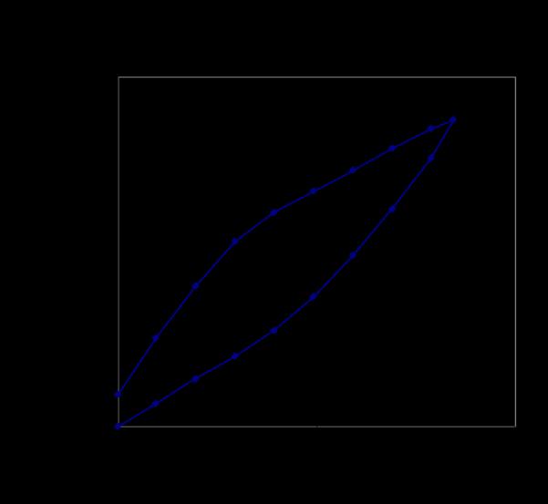
54 Piezo Transfer Function
55 C100-2 cavity operating at ~ 15 MV/m with the PZT off and then on (2 Hz BW). Slow tuner was on in the background. This cryomodule does not have the stiffened tuner mechanism. Slow tuner turns On to re-center The cavity Note 20 minutes/division Thus this is addressing slow pressure drifts PZT bandwidth was limited to 2 Hz

56 Where we are Field control requirements of 0.1 o and 0.1%, phase and amplitude control can be met with modern electronics. Reconfigurable Digital Hardware has made development and operations easier. Challenges - Thoughts Even with moderate specifications of 0.1 o and 0.1%, one has to be careful about mundane issues that affect accuracy and drifts. The assumptions on field control are fast control... not drifts. Drift control... one needs a phase drift budget. Drift control will probably drive hardware configuration and thermal stability issues. PZT active control has room to grow, but cavity to cavity coupling adds to the complexity for frequencies above a few Hertz.
57 Backup Slides
: Large Industrial Base for Piezo and electronics Recover or compensate for Lorentz Detuning (Feed Forward or")
58 Slow Tuner Stepper Motor: Recover cavity from large excursions associated with down time activities quenches or CHL trips. Keep Fast Tuner centered Control can be slow < 1 sec Fast Tuner Piezo-Electric Tuner (PZT): Large Industrial Base for Piezo and electronics Recover or compensate for Lorentz Detuning (Feed Forward or Feedback) Minimizes small changes in resonance do to He pressure. Control logic embedded in FPGA or fast DSP Concern regarding aging effects. Time domain detuning for the open loop case (blue curve) and a combined feedback and feedforward controller (black curve) at a QL of 6.4e7 Single cavity test in HOBiCAT A. Neumann SRF2007, data taken on sc cavities at HZB
59 GDR Advantages - Where fast/deterministic lock up times are critical Disadvantages - High Q machines with high microphonic content and large Lorentz detuning could go unstable Reference Phase Controller Amplitude Controller Klystron SEL Advantages - High Q L Cavities - Systems with large Lorentz detuning Disadvantages - Slow lock up time Limiter Phase Controller Amplitude Controller Klystron Phase Set Point Amplitude Set Point Loop Phase Amplitude Set Point Reference SC Cavity SC Cavity Phase Set Point Phase Detector
60 Parameter Specification Value Imposing Quantities S/N 72 db 0.1 degree resolution, 0.01% gradient accuracy Receiver Bandwidth 8 MHz Latency, S/N, temperature stability Latency 100 ns Control BW Noise Figure (NF) 52 db, BW = 100 khz S/N for phase resolution Linearity 0.01% F.S. Stability, accuracy Dynamic Range +54 dbm IIP3 Gradient range Channel Isolation 67 db Phase, gradient resolution/accuracy In-band intermodulation distortion (IMD) 67 dbc THD
61 Receiver S/N determines minimum residual amplitude control. Amplifiers Mixer ADC Linear components needed for stability and accuracy over large dynamic range. It is possible to improve S/N, through process gain, but at the expense of control bandwidth and ultimately stability (latency). Measured amplitude error vs. proportional gain for a digital receiver (14 bit). Over sampling improved S/N from 74 db to ~ 85 db. Measurements done on 14 bit system packaged in VME format.


62 Analog or Digital System Both analog and digital systems can be made to work. With an analog system the design effort is in the analog circuitry and once it is built changes are limited or expensive. Digital systems provide better opportunities for incremental improvements of algorithms and functionality by reprogramming the FPGA and real time computing software. My experience is that analog systems are more prone to drifts and calibration errors. Pulsed feed forward systems will require some type of adaptive digital controls with an analog system one would have to create analog signals to feed into the LLRF controls. These analog signals would be susceptible to issues like ground loop noise.
63 The Vector Sum There are cost optimization reasons to consider using one large RF source for multiple cavities. When using such a system the common approach is to sacrifice the gradient and phase regulation in one cavity while maintaining the gradient and phase regulation in the aggregate of the cavities. Variable waveguide couplers and phase shifters are used in order to set the relative phase and gradient of each cavity. Normally these are slow devices rather than dynamic control. Multiple receivers are used to monitor all of the cavity field signals. The I signals and the Q signals are summed in the FPGA and the sum of each is controlled using a PID loop. A single drive channel is used to provide RF to the input of the klystron. There are applications where such a system is less than ideal. One example his injectors where cavities are operated at different gradients and phases due to space charge effects and cavity focusing effects. There are operating regimes where there is a strong potential for Lorentz force driven instabilities.
64 The Vector Sum There are cost optimization reasons to consider using one large RF source for multiple cavities. When using such a system the common approach is to sacrifice the gradient and phase regulation in one cavity while maintaining the gradient and phase regulation in the aggregate of the cavities. Variable waveguide couplers and phase shifters are used in order to set the relative phase and gradient of each cavity. Normally these are slow devices rather than dynamic control. Multiple receivers are used to monitor all of the cavity field signals. The I signals and the Q signals are summed in the FPGA and the sum of each is controlled using a PID loop. A single drive channel is used to provide RF to the input of the klystron. There are applications where such a system is less than ideal. One example his injectors where cavities are operated at different gradients and phases due to space charge effects and cavity focusing effects. There are operating regimes where there is a strong potential for Lorentz force driven instabilities.

65 Gen 1: CESR LLRF Control System Vivian Ho LLRF Workshop

66 Gen 1: CESR LLRF Control System Vivian Ho LLRF Workshop
 Down-converting channels: Incident and Reflected RF (402.")
67 SNS VXI format Single Cavity single RF amplifier. Secondary module to monitor the amplitude of the signals generated at the HOM ports. Analog Front End (AFE) Down-converting channels: Incident and Reflected RF (402.5 or 805 MHz) IF channels: Cavity and Reference (50 MHz) Digital Front End (DFE) Four 14 bit, 40 MHz ADC channels One Virtex II FPGA (XC2V M gates) RF Output (RFO) Clock & PLL circuitry One 14 bit, 80 MHz DAC Up-Conversion to 402.5/805 MHz Filtering Champion, M. LLRF 2005


68 Dimtel, Inc Bunch-by-bunch feedback processors; RF front and back ends for bunchby-bunch feedback; Bunch-by-bunch current monitors; Bunch-by-bunch data recorders; General-purpose gigasample digital signal processing channels; Low-level RF processors. Located in San Jose, CA, USA LLRF-4 Evaluation board

69 Instrumentation Technologies Digital LLRF systems Beam Position Monitros Clock Distribution Systems Bunch by Bunch Feedback systems Photon Beam Processor Located in Solkan, Slovenia Libera Digital LLRF System
70 Microphonics and Frequency Drifts SRF cavity frequency shifts can come from multiple sources. Slow Helium fluctuations Vibrations can be driven by external narrow band sources such as HVAC motors, cooling water systems, cryogenic systems. They can also driven by broad band noise which, in general, will excite the resonant modes of the structure. In my opinion slow sub-hertz frequency drifts, such as due to slow pressure fluctuations, are frequency drifts while frequency shifts which have higher frequency content are considered microphonics effects.
71 Microphonics Measurement SEL mode use I and Q and the following equation: ff ii = QQ iiii ii+1 II ii QQ ii+1 2ππ tt QQ ii 2 + II ii 2 Where Δt Is the sample rate of I and Q. In some cases individuals use: φφ ii = cccccc 1 and II ii II ii 2 + QQ ii 2 ff ii = φφ ii φφ ii 1 tt Which after enough math is the same as the equation at the top of the page.
72 Microphonics Measurement GDR mode, use the phase difference between the forward and transmitted power (φ) and the following equation (no beam) ff = ff 0 2QQ LL TTTTTT 1 φφ More on microphonics yesterday
Microphonics. T. Powers
 Microphonics T. Powers What is microphonics? Microphonics is the time domain variation in cavity frequency driven by external vibrational sources. A 1.5 GHz structure 0.5 m long will change in frequency
Low-Level RF. S. Simrock, DESY. MAC mtg, May 05 Stefan Simrock DESY
 Low-Level RF S. Simrock, DESY Outline Scope of LLRF System Work Breakdown for XFEL LLRF Design for the VUV-FEL Cost, Personpower and Schedule RF Systems for XFEL RF Gun Injector 3rd harmonic cavity Main
Theory and Practice of Cavity Test Systems. Tom Powers
 Theory and Practice of Cavity Test Systems Tom Powers SRF Workshop 2005 Tutorial Session INTRODUCTION Over the past 17 years we have done about 2500 cold cavity tests on more than 500 different cavities
Cavity Field Control - RF Field Controller. LLRF Lecture Part3.3 S. Simrock, Z. Geng DESY, Hamburg, Germany
 Cavity Field Control - RF Field Controller LLRF Lecture Part3.3 S. Simrock, Z. Geng DESY, Hamburg, Germany Content Introduction to the controller Control scheme selection In-phase and Quadrature (I/Q)
Digital Self Excited Loop Implementation and Experience. Trent Allison Curt Hovater John Musson Tomasz Plawski
 Digital Self Excited Loop Implementation and Experience Trent Allison Curt Hovater John Musson Tomasz Plawski Overview Why Self Excited Loop? Algorithm Building Blocks Hardware and Sampling Digital Signal
Digital LLRF Test on the Renascence Cryomodule
 Digital LLRF Test on the Renascence Cryomodule Trent Allison, Rama Bachimanchi, Curt Hovater, John Musson and Tomasz Plawski Introduction The Renascence cryomodule was the first opportunity for testing
ABSTRACT 1 CEBAF UPGRADE CAVITY/CRYOMODULE
 Energy Content (Normalized) SC Cavity Resonance Control System for the 12 GeV Upgrade Cavity: Requirements and Performance T. Plawski, T. Allison, R. Bachimanchi, D. Hardy, C. Hovater, Thomas Jefferson
Borut Baricevic. Libera LLRF. 17 September 2009
 Borut Baricevic Libera LLRF borut.baricevic@i-tech.si 17 September 2009 Outline Libera LLRF introduction Libera LLRF system topology Signal processing structure GUI and signal acquisition RF system diagnostics
Review on Progress in RF Control Systems. Cornell University. Matthias Liepe. M. Liepe, Cornell U. SRF 2005, July 14
 Review on Progress in RF Control Systems Matthias Liepe Cornell University 1 Why this Talk? As we all know, superconducting cavities have many nice features one of which is very high field stability. Why?
SNS LLRF Design Experience and its Possible Adoption for the ILC
 SNS LLRF Design Experience and its Possible Adoption for the ILC Brian Chase SNS - Mark Champion Fermilab International Linear Collider Workshop 11/28/2005 1 Why Consider the SNS System for ILC R&D at
C100 Cryomodule. Seven cell Cavity, 0.7 m long (high Q L ) 8 Cavities per Cryomodule Fits the existing Cryomodule footprint
 8 Cavities per Cryomodule Fits the existing Cryomodule footprint") 1 new module C100 Cryomodule Seven cell Cavity, 0.7 m long (high Q L ) 8 Cavities per Cryomodule Fits the existing Cryomodule footprint Fundamental frequency f 0 Accelerating gradient E acc 1497 MHz >
1 new module C100 Cryomodule Seven cell Cavity, 0.7 m long (high Q L ) 8 Cavities per Cryomodule Fits the existing Cryomodule footprint Fundamental frequency f 0 Accelerating gradient E acc 1497 MHz >
Cavity Testing Mathematics. Tom Powers USPAS SRF Testing Course 19 Jan. 2014
 Cavity Testing Mathematics Tom Powers USPAS SRF Testing Course 19 Jan. 014 General Block Diagram for Vertical or Horizontal Test Stand Frequency tracking source can be either a VCO-PLL based system or
R.Bachimanchi, IPAC, May 2015, Richmond, VA
 1 new module C100 Cryomodule Seven cell Cavity, 0.7 m long (high Q L ) 8 Cavities per Cryomodule Fits the existing Cryomodule footprint Fundamental frequency f 0 Accelerating gradient E acc 1497 MHz >
Direct Digital Down/Up Conversion for RF Control of Accelerating Cavities
 Direct Digital Down/Up Conversion for RF Control of Accelerating Cavities C. Hovater, T. Allison, R. Bachimanchi, J. Musson and T. Plawski Introduction As digital receiver technology has matured, direct
FLASH rf gun. beam generated within the (1.3 GHz) RF gun by a laser. filling time: typical 55 μs. flat top time: up to 800 μs
 RF gun by a laser. filling time: typical 55 μs. flat top time: up to 800 μs") The gun RF control at FLASH (and PITZ) Elmar Vogel in collaboration with Waldemar Koprek and Piotr Pucyk th FLASH Seminar at December 19 2006 FLASH rf gun beam generated within the (1.3 GHz) RF gun by
The gun RF control at FLASH (and PITZ) Elmar Vogel in collaboration with Waldemar Koprek and Piotr Pucyk th FLASH Seminar at December 19 2006 FLASH rf gun beam generated within the (1.3 GHz) RF gun by
Performance of the Prototype NLC RF Phase and Timing Distribution System *
 SLAC PUB 8458 June 2000 Performance of the Prototype NLC RF Phase and Timing Distribution System * Josef Frisch, David G. Brown, Eugene Cisneros Stanford Linear Accelerator Center, Stanford University,
Digital Low Level RF for SESAME
 Technical Sector Synchrotron-light for Experimental Science And Applications in the Middle East Subject : RF More specified area: Digital Low Level RF Date: 6/23/2010 Total Number of Pages: 11 Document
Software Requirements Specification for LLRF Applications at FLASH Version 1.0 Prepared by Zheqiao Geng MSK, DESY Nov. 06, 2009
 Software Specification for LLRF Applications at FLASH Version 1.0 Prepared by Zheqiao Geng MSK, DESY Nov. 06, 2009 Copyright 2009 by Zheqiao Geng. Any change of this document should be agreed by the development
Digital Logic, Algorithms, and Functions for the CEBAF Upgrade LLRF System Hai Dong, Curt Hovater, John Musson, and Tomasz Plawski
 Digital Logic, Algorithms, and Functions for the CEBAF Upgrade LLRF System Hai Dong, Curt Hovater, John Musson, and Tomasz Plawski Introduction: The CEBAF upgrade Low Level Radio Frequency (LLRF) control
Waveguide Arc Restrike Test Results Abstract Background
 Waveguide Arc Restrike Test Results Tom Powers, Doug Curry, Kirk Davis, Larry King, and Mike Tiefenback Thomas Jefferson National Accelerator Facility (Test dates July 6, 2004 through September 2, 2004)
Beam Diagnostics, Low Level RF and Feedback for Room Temperature FELs. Josef Frisch Pohang, March 14, 2011
 Beam Diagnostics, Low Level RF and Feedback for Room Temperature FELs Josef Frisch Pohang, March 14, 2011 Room Temperature / Superconducting Very different pulse structures RT: single bunch or short bursts
Reconfigurable 6 GHz Vector Signal Transceiver with I/Q Interface
 SPECIFICATIONS PXIe-5645 Reconfigurable 6 GHz Vector Signal Transceiver with I/Q Interface Contents Definitions...2 Conditions... 3 Frequency...4 Frequency Settling Time... 4 Internal Frequency Reference...
State of the Art in RF Control
 State of the Art in RF Control S. Simrock, DESY LINAC 2004, Lübeck Stefan Simrock DESY Outline RF System Architecture Requirements for RF Control RF Control Design Considerations Design Efforts Worldwide
Costas Loop. Modules: Sequence Generator, Digital Utilities, VCO, Quadrature Utilities (2), Phase Shifter, Tuneable LPF (2), Multiplier
, Phase Shifter, Tuneable LPF (2), Multiplier") Costas Loop Modules: Sequence Generator, Digital Utilities, VCO, Quadrature Utilities (2), Phase Shifter, Tuneable LPF (2), Multiplier 0 Pre-Laboratory Reading Phase-shift keying that employs two discrete
Costas Loop Modules: Sequence Generator, Digital Utilities, VCO, Quadrature Utilities (2), Phase Shifter, Tuneable LPF (2), Multiplier 0 Pre-Laboratory Reading Phase-shift keying that employs two discrete
PN9000 PULSED CARRIER MEASUREMENTS
 The specialist of Phase noise Measurements PN9000 PULSED CARRIER MEASUREMENTS Carrier frequency: 2.7 GHz - PRF: 5 khz Duty cycle: 1% Page 1 / 12 Introduction When measuring a pulse modulated signal the
Design considerations for the RF phase reference distribution system for X-ray FEL and TESLA
 Design considerations for the RF phase reference distribution system for X-ray FEL and TESLA Krzysztof Czuba *a, Henning C. Weddig #b a Institute of Electronic Systems, Warsaw University of Technology,
Section 1. Fundamentals of DDS Technology
 Section 1. Fundamentals of DDS Technology Overview Direct digital synthesis (DDS) is a technique for using digital data processing blocks as a means to generate a frequency- and phase-tunable output signal
RF Signal Generators. SG380 Series DC to 2 GHz, 4 GHz and 6 GHz analog signal generators. SG380 Series RF Signal Generators
 RF Signal Generators SG380 Series DC to 2 GHz, 4 GHz and 6 GHz analog signal generators SG380 Series RF Signal Generators DC to 2 GHz, 4 GHz or 6 GHz 1 µhz resolution AM, FM, ΦM, PM and sweeps OCXO timebase
The low level radio frequency control system for DC-SRF. photo-injector at Peking University *
 The low level radio frequency control system for DC-SRF photo-injector at Peking University * WANG Fang( 王芳 ) 1) FENG Li-Wen( 冯立文 ) LIN Lin( 林林 ) HAO Jian-Kui( 郝建奎 ) Quan Sheng-Wen( 全胜文 ) ZHANG Bao-Cheng(
RF Locking of Femtosecond Lasers
 RF Locking of Femtosecond Lasers Josef Frisch, Karl Gumerlock, Justin May, Steve Smith SLAC Work supported by DOE contract DE-AC02-76SF00515 1 Overview FEIS 2013 talk discussed general laser locking concepts
SIGNAL RECOVERY. Model 7265 DSP Lock-in Amplifier
 Model 7265 DSP Lock-in Amplifier FEATURES 0.001 Hz to 250 khz operation Voltage and current mode inputs Direct digital demodulation without down-conversion 10 µs to 100 ks output time constants Quartz
RF/IF Terminology and Specs
 RF/IF Terminology and Specs Contributors: Brad Brannon John Greichen Leo McHugh Eamon Nash Eberhard Brunner 1 Terminology LNA - Low-Noise Amplifier. A specialized amplifier to boost the very small received
Slide Title. Bulleted Text
 Slide Title 1 Slide Outline Title Brief view of the C-AD Complex Review of the RHIC LLRF Upgrade Platform Generic Implementation of a Feedback Loop RHIC Bunch by Bunch Longitudinal Damper Cavity Controller
Vector Network Analyzers (VERY) Basics. Tom Powers USPAS SRF Testing Course 19 Jan. 2014
 Basics. Tom Powers USPAS SRF Testing Course 19 Jan. 2014") Vector Network Analyzers (VERY) Basics Tom Powers USPAS SRF Testing Course 19 Jan. 2014 S-Parameters A scattering matrix relates the voltage waves incident on the ports of a network to those reflected
Vector Network Analyzers (VERY) Basics Tom Powers USPAS SRF Testing Course 19 Jan. 2014 S-Parameters A scattering matrix relates the voltage waves incident on the ports of a network to those reflected
Linac Coherent Light Source (LCLS) Low Level RF Status LCLS FAC. October 30, 2007
 Low Level RF Status LCLS FAC. October 30, 2007") Linac Coherent Light Source (LCLS) Low Level RF Status LCLS Emma LCLS RF Gun, L0, and L1 Emma Dual Feed L0A L0B L0A 57MV 19MV/m L0B 72MV 24MV/m Off Axis Injector Vault Injector Transverse Accelerator 55cm
Linac Coherent Light Source (LCLS) Low Level RF Status LCLS Emma LCLS RF Gun, L0, and L1 Emma Dual Feed L0A L0B L0A 57MV 19MV/m L0B 72MV 24MV/m Off Axis Injector Vault Injector Transverse Accelerator 55cm
National Accelerator Laboratory
 Fermi National Accelerator Laboratory FERMILAB-Conf-96/103 Trigger Delay Compensation for Beam Synchronous Sampling James Steimel Fermi National Accelerator Laboratory P.O. Box 500, Batavia, Illinois 60510
DEVELOPMENT OF A DLLRF USING COMERCIAL UTCA PLATFORM
 ACDIV-2017-11 May 2017 DEVELOPMENT OF A DLLRF USING COMERCIAL UTCA PLATFORM A. Salom, E. Morales, F. Pérez - ALBA Synchrotron Abstract The Digital LLRF of ALBA has been implemented using commercial cpci
R100 Microphonics. Kirk Davis, Mike Drury, Leigh Harwood, Mark Wiseman, etc. Andrew Hutton
 R100 Microphonics Andrew Hutton Reporting on work by Kirk Davis, Mike Drury, Leigh Harwood, John Hogan, Kurt Hovater, Thomas Plawski, Mark Wiseman, etc. The Problem Vibrations of the superconducting cavities
Receiver Architecture
 Receiver Architecture Receiver basics Channel selection why not at RF? BPF first or LNA first? Direct digitization of RF signal Receiver architectures Sub-sampling receiver noise problem Heterodyne receiver
Satellite Communications: Part 4 Signal Distortions & Errors and their Relation to Communication Channel Specifications. Howard Hausman April 1, 2010
 Satellite Communications: Part 4 Signal Distortions & Errors and their Relation to Communication Channel Specifications Howard Hausman April 1, 2010 Satellite Communications: Part 4 Signal Distortions
A COMPACT, AGILE, LOW-PHASE-NOISE FREQUENCY SOURCE WITH AM, FM AND PULSE MODULATION CAPABILITIES
 A COMPACT, AGILE, LOW-PHASE-NOISE FREQUENCY SOURCE WITH AM, FM AND PULSE MODULATION CAPABILITIES Alexander Chenakin Phase Matrix, Inc. 109 Bonaventura Drive San Jose, CA 95134, USA achenakin@phasematrix.com
Understanding RF and Microwave Analysis Basics
 Understanding RF and Microwave Analysis Basics Kimberly Cassacia Product Line Brand Manager Keysight Technologies Agenda µw Analysis Basics Page 2 RF Signal Analyzer Overview & Basic Settings Overview
Keysight Technologies
 Keysight Technologies Generating Signals Basic CW signal Block diagram Applications Analog Modulation Types of analog modulation Block diagram Applications Digital Modulation Overview of IQ modulation
SC5307A/SC5308A 100 khz to 6 GHz RF Downconverter. Datasheet SignalCore, Inc.
 SC5307A/SC5308A 100 khz to 6 GHz RF Downconverter Datasheet 2017 SignalCore, Inc. support@signalcore.com P RODUCT S PECIFICATIONS Definition of Terms The following terms are used throughout this datasheet
Measuring Non-linear Amplifiers
 Measuring Non-linear Amplifiers Transceiver Components & Measuring Techniques MM3 Jan Hvolgaard Mikkelsen Radio Frequency Integrated Systems and Circuits Division Aalborg University 27 Agenda Non-linear
Effects of Intensity and Position Modulation On Switched Electrode Electronics Beam Position Monitor Systems at Jefferson Lab*
 JLAB-ACT--9 Effects of Intensity and Position Modulation On Switched Electrode Electronics Beam Position Monitor Systems at Jefferson Lab* Tom Powers Thomas Jefferson National Accelerator Facility Newport
RFID Systems: Radio Architecture
 RFID Systems: Radio Architecture 1 A discussion of radio architecture and RFID. What are the critical pieces? Familiarity with how radio and especially RFID radios are designed will allow you to make correct
Single Conversion LF Upconverter Andy Talbot G4JNT Jan 2009
 Single Conversion LF Upconverter Andy Talbot G4JNT Jan 2009 Mark 2 Version Oct 2010, see Appendix, Page 8 This upconverter is designed to directly translate the output from a soundcard from a PC running
Synchronization Overview
 Synchronization Overview S. Simrock, DESY ERL Workshop 2005 Stefan Simrock DESY What is Synchronization Outline Synchronization Requirements for RF, Laser and Beam Timing stability RF amplitude and phase
PLL Synchronizer User s Manual / Version 1.0.6
 PLL Synchronizer User s Manual / Version 1.0.6 AccTec B.V. Den Dolech 2 5612 AZ Eindhoven The Netherlands phone +31 (0) 40-2474321 / 4048 e-mail AccTecBV@tue.nl Contents 1 Introduction... 3 2 Technical
Keywords: GPS, receiver, GPS receiver, MAX2769, 2769, 1575MHz, Integrated GPS Receiver, Global Positioning System
 Maxim > Design Support > Technical Documents > User Guides > APP 3910 Keywords: GPS, receiver, GPS receiver, MAX2769, 2769, 1575MHz, Integrated GPS Receiver, Global Positioning System USER GUIDE 3910 User's
Femtosecond Synchronization of Laser Systems for the LCLS
 Femtosecond Synchronization of Laser Systems for the LCLS, Lawrence Doolittle, Gang Huang, John W. Staples, Russell Wilcox (LBNL) John Arthur, Josef Frisch, William White (SLAC) 26 Aug 2010 FEL2010 1 Berkeley
Update 5/19/11. Kirk Davis, Mike Drury, Leigh Harwood, Mark Wiseman, etc. Andrew Hutton
 R100 Microphonics i Update 5/19/11 Andrew Hutton Reporting on work by Kirk Davis, Mike Drury, Leigh Harwood, John Hogan, Curt Hovater, Thomas Plawski, Mark Wiseman, etc. The Problem Vibrations of the superconducting
LCLS-II LLRF Prototype Testing and Characterization. Larry Doolittle, Brian Chase, Joshua Einstein-Curtis, Carlos Serrano LLRF 17,
 LCLS-II LLRF Prototype Testing and Characterization Larry Doolittle, Brian Chase, Joshua Einstein-Curtis, Carlos Serrano LLRF 17, 2017-10-16 Outline A little background on LCLS-II LLRF Design - DSP algorithms
Software Design Specification for LLRF Applications at FLASH Version 1.0 Prepared by Zheqiao Geng MSK, DESY Nov. 16, 2009
 Software Design Specification for LLRF Applications at FLASH Version 1.0 Prepared by Zheqiao Geng MSK, DESY Nov. 16, 2009 Copyright 2009 by Zheqiao Geng. Any change of this document should be agreed by
INSTALLATION AND FIRST COMMISSIONING OF THE LLRF SYSTEM
 INSTALLATION AND FIRST COMMISSIONING OF THE LLRF SYSTEM FOR THE EUROPEAN XFEL Julien Branlard, for the LLRF team TALK OVERVIEW 2 Introduction Brief reminder about the XFEL LLRF system Commissioning goals
RF and Microwave Test and Design Roadshow 5 Locations across Australia and New Zealand
 RF and Microwave Test and Design Roadshow 5 Locations across Australia and New Zealand Advanced VNA Measurements Agenda Overview of the PXIe-5632 Architecture SW Experience Overview of VNA Calibration
Design and performance of LLRF system for CSNS/RCS *
 Design and performance of LLRF system for CSNS/RCS * LI Xiao 1) SUN Hong LONG Wei ZHAO Fa-Cheng ZHANG Chun-Lin Institute of High Energy Physics, Chinese Academy of Sciences, Beijing 100049, China Abstract:
FREQUENCY AGILE FM MODULATOR INSTRUCTION BOOK IB
 FMT615C FREQUENCY AGILE FM MODULATOR INSTRUCTION BOOK IB1215-02 TABLE OF CONTENTS SECTION SUBJECT 1.0 Introduction 2.0 Installation & Operating Instructions 3.0 Specification 4.0 Functional Description
Keysight Technologies 8 Hints for Making Better Measurements Using RF Signal Generators. Application Note
 Keysight Technologies 8 Hints for Making Better Measurements Using RF Signal Generators Application Note 02 Keysight 8 Hints for Making Better Measurements Using RF Signal Generators - Application Note
Measurements 2: Network Analysis
 Measurements 2: Network Analysis Fritz Caspers CAS, Aarhus, June 2010 Contents Scalar network analysis Vector network analysis Early concepts Modern instrumentation Calibration methods Time domain (synthetic
note application Measurement of Frequency Stability and Phase Noise by David Owen
 application Measurement of Frequency Stability and Phase Noise note by David Owen The stability of an RF source is often a critical parameter for many applications. Performance varies considerably with
ESS RF Development at Uppsala University. Roger Ruber for the FREIA team Uppsala University
 ESS RF Development at Uppsala University Roger Ruber for the FREIA team Uppsala University ESS-UU Collaboration 2009 ESS and UU start discussion on 704 MHz RF development proposal for ESS dedicated test
INC. MICROWAVE. A Spectrum Control Business
 DRO Selection Guide DIELECTRIC RESONATOR OSCILLATORS Model Number Frequency Free Running, Mechanically Tuned Mechanical Tuning BW (MHz) +10 MDR2100 2.5-6.0 +10 6.0-21.0 +20 Free Running, Mechanically Tuned,
CUSTOM INTEGRATED ASSEMBLIES
 17 CUSTOM INTEGRATED ASSEMBLIES CUSTOM INTEGRATED ASSEMBLIES Cougar offers full first-level integration capabilities, providing not just performance components but also full subsystem solutions to help
SIGNAL GENERATORS. MG3633A 10 khz to 2700 MHz SYNTHESIZED SIGNAL GENERATOR GPIB
 SYNTHESIZED SIGNAL GENERATOR MG3633A GPIB For Evaluating of Quasi-Microwaves and Measuring High-Performance Receivers The MG3633A has excellent resolution, switching speed, signal purity, and a high output
Phase Drift Budget Analysis for 12 GeV 1497 MHz LLRF System
 Phase Drift Budget Analysis for 12 GeV 1497 MHz LLRF System John Musson 28-Sept-7 Introduction The 12 GeV upgrade effort included the creation of LLRF Requirements, directed at achieving.4% gradient regulation,.5
FREQUENCY SYNTHESIZERS, SIGNAL GENERATORS
 SYNTHESIZED SIGNAL GENERATOR MG3641A/MG3642A 12 khz to 1040/2080 MHz NEW New Anritsu synthesizer technology permits frequency to be set with a resolution of 0.01 Hz across the full frequency range. And
Amplitude and Phase Stability of Analog Components for the LLRF System of the PEFP Accelerator
 Journal of the Korean Physical Society, Vol. 52, No. 3, March 2008, pp. 766770 Amplitude and Phase Stability of Analog Components for the LLRF System of the PEFP Accelerator Kyung-Tae Seol, Hyeok-Jung
Digital Signal Processing in RF Applications
 Digital Signal Processing in RF Applications Part II Thomas Schilcher Outline 1. signal conditioning / down conversion 2. detection of amp./phase by digital I/Q sampling I/Q sampling non I/Q sampling digital
Utilizzo del Time Domain per misure EMI
 Utilizzo del Time Domain per misure EMI Roberto Sacchi Measurement Expert Manager - Europe 7 Giugno 2017 Compliance EMI receiver requirements (CISPR 16-1-1 ) range 9 khz - 18 GHz: A normal +/- 2 db absolute
Agilent ESA-L Series Spectrum Analyzers
 Agilent ESA-L Series Spectrum Analyzers Data Sheet Available frequency ranges E4403B E4408B 9 khz to 1.5 GHz 9 khz to 3.0 GHz 9 khz to 26.5 GHz As the lowest cost ESA option, these basic analyzers are
Understanding Low Phase Noise Signals. Presented by: Riadh Said Agilent Technologies, Inc.
 Understanding Low Phase Noise Signals Presented by: Riadh Said Agilent Technologies, Inc. Introduction Instabilities in the frequency or phase of a signal are caused by a number of different effects. Each
Data Sheet SC5317 & SC5318A. 6 GHz to 26.5 GHz RF Downconverter SignalCore, Inc. All Rights Reserved
 Data Sheet SC5317 & SC5318A 6 GHz to 26.5 GHz RF Downconverter www.signalcore.com 2018 SignalCore, Inc. All Rights Reserved Definition of Terms 1 Table of Contents 1. Definition of Terms... 2 2. Description...
Wideband Receiver for Communications Receiver or Spectrum Analysis Usage: A Comparison of Superheterodyne to Quadrature Down Conversion
 A Comparison of Superheterodyne to Quadrature Down Conversion Tony Manicone, Vanteon Corporation There are many different system architectures which can be used in the design of High Frequency wideband
SHRI ANGALAMMAN COLLEGE OF ENGINEERING & TECHNOLOGY (An ISO 9001:2008 Certified Institution) SIRUGANOOR,TRICHY
 SIRUGANOOR,TRICHY") SHRI ANGALAMMAN COLLEGE OF ENGINEERING & TECHNOLOGY (An ISO 9001:2008 Certified Institution) SIRUGANOOR,TRICHY-621105. DEPARTMENT OF ELECTRICAL AND ELECTRONICS ENGINEERING EI 1306-MEASUREMENT AND INSTRUMENTATION
SHRI ANGALAMMAN COLLEGE OF ENGINEERING & TECHNOLOGY (An ISO 9001:2008 Certified Institution) SIRUGANOOR,TRICHY-621105. DEPARTMENT OF ELECTRICAL AND ELECTRONICS ENGINEERING EI 1306-MEASUREMENT AND INSTRUMENTATION
Keysight Technologies PNA-X Series Microwave Network Analyzers
 Keysight Technologies PNA-X Series Microwave Network Analyzers Active-Device Characterization in Pulsed Operation Using the PNA-X Application Note Introduction Vector network analyzers (VNA) are the common
Overview of ERL Projects: SRF Issues and Challenges. Matthias Liepe Cornell University
 Overview of ERL Projects: SRF Issues and Challenges Matthias Liepe Cornell University Overview of ERL projects: SRF issues and challenges Slide 1 Outline Introduction: SRF for ERLs What makes it special
ANALOG COMMUNICATION
 ANALOG COMMUNICATION TRAINING LAB Analog Communication Training Lab consists of six kits, one each for Modulation (ACL-01), Demodulation (ACL-02), Modulation (ACL-03), Demodulation (ACL-04), Noise power
- RF Master-Reference Update (F.Ludwig, H.Weddig - DESY, K.Czuba - TU Warsaw) - Beam Stability Update (C.Gerth, F.Ludwig, G.
 - Beam Stability Update (C.Gerth, F.Ludwig, G.") FLASH Meeting, 21/04/09 Beam Stability at FLASH - update F.Ludwig - DESY Content : - Motivation - RF Master-Reference Update (F.Ludwig, H.Weddig - DESY, K.Czuba - TU Warsaw) - Beam Stability Update (C.Gerth,
FLASH Meeting, 21/04/09 Beam Stability at FLASH - update F.Ludwig - DESY Content : - Motivation - RF Master-Reference Update (F.Ludwig, H.Weddig - DESY, K.Czuba - TU Warsaw) - Beam Stability Update (C.Gerth,
LLRF4 Evaluation Board
 LLRF4 Evaluation Board USPAS Lab Reference Author: Dmitry Teytelman Revision: 1.1 June 11, 2009 Copyright Dimtel, Inc., 2009. All rights reserved. Dimtel, Inc. 2059 Camden Avenue, Suite 136 San Jose, CA
EE-4022 Experiment 3 Frequency Modulation (FM)
") EE-4022 MILWAUKEE SCHOOL OF ENGINEERING 2015 Page 3-1 Student Objectives: EE-4022 Experiment 3 Frequency Modulation (FM) In this experiment the student will use laboratory modules including a Voltage-Controlled
EE-4022 MILWAUKEE SCHOOL OF ENGINEERING 2015 Page 3-1 Student Objectives: EE-4022 Experiment 3 Frequency Modulation (FM) In this experiment the student will use laboratory modules including a Voltage-Controlled
TETRA Tx Test Solution
 Product Introduction TETRA Tx Test Solution Signal Analyzer Reference Specifications ETSI EN 300 394-1 V3.3.1(2015-04) / Part1: Radio ETSI TS 100 392-2 V3.6.1(2013-05) / Part2: Air Interface May. 2016
Model 865 RF / Ultra Low Noise Microwave Signal Generator
 Model 865 RF / Ultra Low Noise Microwave Signal Generator Features Excellent signal purity: ultra-low phase noise and low spurious Combination of highest output power and fastest switching Powerful touch-display
HF Receivers, Part 2
 HF Receivers, Part 2 Superhet building blocks: AM, SSB/CW, FM receivers Adam Farson VA7OJ View an excellent tutorial on receivers NSARC HF Operators HF Receivers 2 1 The RF Amplifier (Preamp)! Typical
EUROFEL-Report-2006-DS EUROPEAN FEL Design Study
 EUROFEL-Report-2006-DS3-034 EUROPEAN FEL Design Study Deliverable N : D 3.8 Deliverable Title: RF Amplitude and Phase Detector Task: Author: DS-3 F.Ludwig, M.Hoffmann, M.Felber, Contract N : 011935 P.Strzalkowski,
Design & Implementation of the LLRF System for LCLS-II. Andy Benwell (SLAC Spokesperson) LLRF 2017 October 16, 2017
 LLRF 2017 October 16, 2017") Design & Implementation of the LLRF System for LCLS-II Andy Benwell (SLAC Spokesperson) LLRF 2017 October 16, 2017 Outline LCLS II LCLS II LLRF Requirements/Parameters LLRF Team LLRF Design Testing efforts
Design & Implementation of the LLRF System for LCLS-II Andy Benwell (SLAC Spokesperson) LLRF 2017 October 16, 2017 Outline LCLS II LCLS II LLRF Requirements/Parameters LLRF Team LLRF Design Testing efforts
1. Explain how Doppler direction is identified with FMCW radar. Fig Block diagram of FM-CW radar. f b (up) = f r - f d. f b (down) = f r + f d
 = f r - f d. f b (down) = f r + f d") 1. Explain how Doppler direction is identified with FMCW radar. A block diagram illustrating the principle of the FM-CW radar is shown in Fig. 4.1.1 A portion of the transmitter signal acts as the reference
1. Explain how Doppler direction is identified with FMCW radar. A block diagram illustrating the principle of the FM-CW radar is shown in Fig. 4.1.1 A portion of the transmitter signal acts as the reference
ALICE SRF SYSTEM COMMISSIONING EXPERIENCE A. Wheelhouse ASTeC, STFC Daresbury Laboratory
 ALICE SRF SYSTEM COMMISSIONING EXPERIENCE A. Wheelhouse ASTeC, STFC Daresbury Laboratory ERL 09 8 th 12 th June 2009 ALICE Accelerators and Lasers In Combined Experiments Brief Description ALICE Superconducting
New apparatus for precise synchronous phase shift measurements in storage rings 1
 New apparatus for precise synchronous phase shift measurements in storage rings 1 Boris Podobedov and Robert Siemann Stanford Linear Accelerator Center, Stanford University, Stanford, CA 94309 Measuring
Optical Delay Line Application Note
 1 Optical Delay Line Application Note 1.1 General Optical delay lines system (ODL), incorporates a high performance lasers such as DFBs, optical modulators for high operation frequencies, photodiodes,
Session 3. CMOS RF IC Design Principles
 Session 3 CMOS RF IC Design Principles Session Delivered by: D. Varun 1 Session Topics Standards RF wireless communications Multi standard RF transceivers RF front end architectures Frequency down conversion
arxiv: v1 [physics.acc-ph] 23 Mar 2018
![arxiv: v1 [physics.acc-ph] 23 Mar 2018](/thumbs/96/128693379.jpg "arxiv: v1 [physics.acc-ph] 23 Mar 2018") LLRF SYSTEM FOR THE FERMILAB MUON G-2 AND MU2E PROJECTS P. Varghese, B. Chase Fermi National Accelerator Laboratory (FNAL), Batavia, IL 60510, USA arxiv:1803.08968v1 [physics.acc-ph] 23 Mar 2018 Abstract
LLRF SYSTEM FOR THE FERMILAB MUON G-2 AND MU2E PROJECTS P. Varghese, B. Chase Fermi National Accelerator Laboratory (FNAL), Batavia, IL 60510, USA arxiv:1803.08968v1 [physics.acc-ph] 23 Mar 2018 Abstract
Differential Amplifiers
 Differential Amplifiers Benefits of Differential Signal Processing The Benefits Become Apparent when Trying to get the Most Speed and/or Resolution out of a Design Avoid Grounding/Return Noise Problems
Keysight Technologies E8257D PSG Microwave Analog Signal Generator. Data Sheet
 Keysight Technologies E8257D PSG Microwave Analog Signal Generator Data Sheet 02 Keysight E8257D Microwave Analog Signal Generator - Data Sheet Table of Contents Specifications... 4 Frequency... 4 Step
Measurement and Analysis for Switchmode Power Design
 Measurement and Analysis for Switchmode Power Design Switched Mode Power Supply Measurements AC Input Power measurements Safe operating area Harmonics and compliance Efficiency Switching Transistor Losses
10 GHz Microwave Link
 10 GHz Microwave Link Project Project Objectives System System Functionality Testing Testing Procedures Cautions and Warnings Problems Encountered Recommendations Conclusion PROJECT OBJECTIVES Implement
MICROWAVE MICROWAVE TRAINING BENCH COMPONENT SPECIFICATIONS:
 Microwave section consists of Basic Microwave Training Bench, Advance Microwave Training Bench and Microwave Communication Training System. Microwave Training System is used to study all the concepts of
PXIe Contents SPECIFICATIONS. 14 GHz and 26.5 GHz Vector Signal Analyzer
 SPECIFICATIONS PXIe-5668 14 GHz and 26.5 GHz Vector Signal Analyzer These specifications apply to the PXIe-5668 (14 GHz) Vector Signal Analyzer and the PXIe-5668 (26.5 GHz) Vector Signal Analyzer with
General configuration
 Transmitter General configuration In some cases the modulator operates directly at the transmission frequency (no up conversion required) In digital transmitters, the information is represented by the