Crystal Radio Engineering Diode Detectors
|
|
|
- Darren Simon
- 6 years ago
- Views:
Transcription
1 by Kenneth A. Kuhn Feb. 3, 2008, (draft more to come) A diode is a non-linear device that conducts electrical current significantly better in what is referred to as the forward direction than in the reverse direction. This process can convert an AC signal to a DC signal through a process known as rectification. If the amplitude of a high-frequency AC signal is varying in response to a low-frequency amplitude modulation (such as audio) then rectification will result in a varying DC signal with the modulation superimposed. The original audio signal is recovered by discarding the DC term. Although the term, threshold, is often used in discussions about diodes in regards to some minimum signal no actual threshold exists. The forward resistance of the diode generally has a reciprocal relation to the forward current i.e. the diode conducts better as the forward current increases. The poor conductivity of diodes at very low currents gives rise to the threshold discusion. A diode idealy has no conductivity in the reverse direction although all diodes will exhibit some reverse conductivity and a number of excellent microwave diodes have significant reverse conductivity as a consequence of their internal structure. Reverse conductivity works against us but what is more generally important is the ratio of forward to reverse conductivity the higher the better. Diodes in the early days of radio were homemade and typically consisted of the junction of some metal such as a stiff wire against a non-metallic conductor. Considerable effort was required to locate a sweet spot that had good diode qualities. Some purists stil insist on this method today and that is fine but I highly recommend that you purchase a manufactured diode (such as a 1N277) made for the intended purpose. You will be much happier and satisfied with the performance. After you have a working crystal radio you can experiment with ancient methods always begin with a working circuit before trying something different or challenging. Commercial diodes that can be used for crystal radios include the germanium diodes 1N34 and 1N277 (note: the 1N277 has in most cases replaced the old 1N34), silicon diodes such as the 1N914 and 1N4148, and a variety of microwave diodes with the Avago (formerly Agilent and formerly HP) being a popular choice. Until the advent of microwave diodes the germanium diodes were and still are very popular because they work so well for crystal radios. Microwave diodes were never intended for use in crystal radios but they have significantly better conduction that silicon although they are not as good as germanium. However, germanium diodes are sometimes hard to find and microwave diodes are relatively easy to find. Some microwave diodes have a noticeable reverse conductivity which detracts from their performance but overall many microwave diodes can do an excellent job. I would definitely try several of them. Silicon diodes are a poor choice for crystal radios because they have very low conductivity at very low currents i.e. they are very lossy. But, if you are in a strong signal area and do not have better diodes, then silicon is much better than nothing and you can make a working crystal radio. But, you will want to upgrade to a diode better for 1
2 the purpose as soon as you can. If you are driving very high impedance headphones such as the crystal type then you may find that silicon is not too bad. Figure 1 shows the current versus voltage curves for several common diodes. These plots were made using an XY recorder. Note that the germanium diode shows significantly better forward conductance than the other diodes. On the scale shown it is possible to see the reverse resistance of that diode which is about 100 k. The reverse current for the other diodes does not show up on the scale. Note that the forward current of the silicon diode barely shows up on the scale. The silicon 1N4148 diode barely shows any forward conductivity at these low forward voltages. This graph clearly shows why silicon diodes do not work well in crystal radios. The transfer curve of a popular microwave diode is also shown. The diode has significantly better forward conduction than silicon but is not as good as germanium. 2

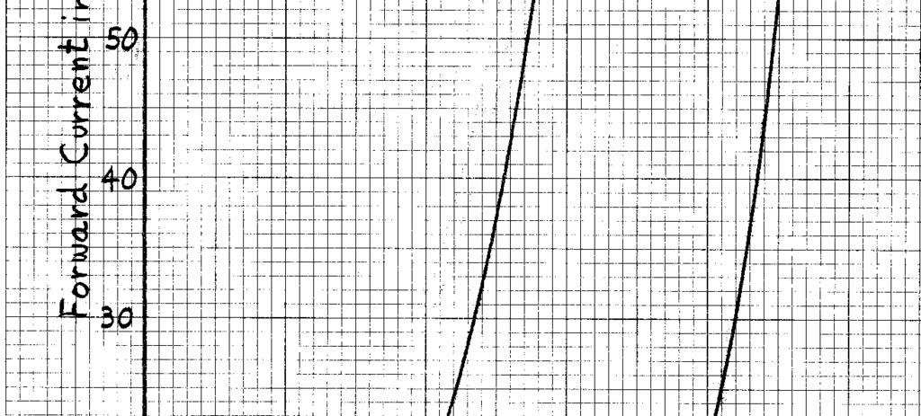
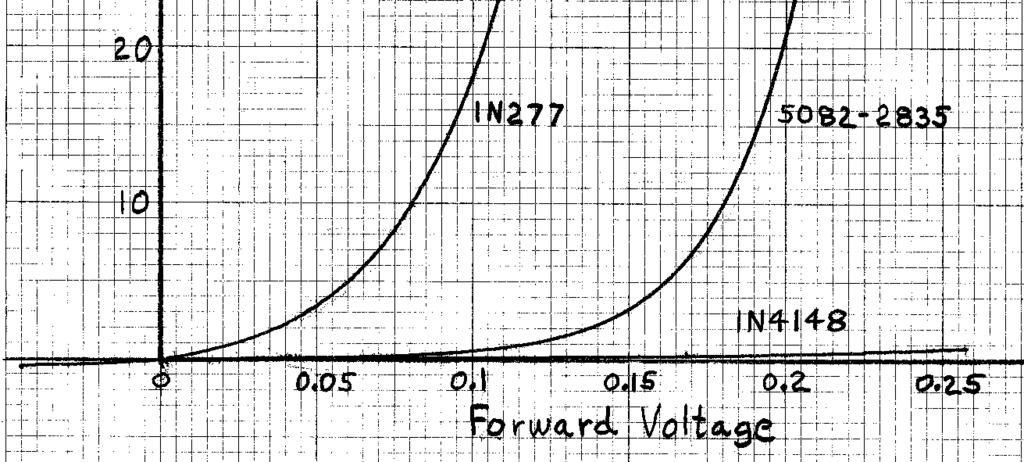
3 Figure 1: Diode Curves 3
4 There are two fundamental types of rectifier circuits, series and shunt. Series is probably the most common but shunt can work well too. I recommend that you try both. Whether series or shunt, the most common circuit is half-wave using only a single diode. Neither of these two types of rectifier circuits is superior to the other. But there are various esoteric viewpoints that drive different people to one or the other configurations. My advice is to use the one you like. It is desirable to perform the rectification process at the highest voltage possible in the radio. This voltage is the entire voltage across the resonant circuit. One problem with this is that the headphone impedance may be low which will result in the tuned circuit being overloaded thus low signal and poor selectivity. There are two solutions. One is to connect the diode to an appropriate lower impedance tap on the inductor. The other is to use a transformer to magnify the headphone impedance. Each method can work but the second method is the better option if the right transformer is available. Otherwise the first option is better. Small signal audio transformers tend to be very lossy. It is not uncommon to lose 30 to 50 percent of the audio power. If you use a transformer, consider a larger one physically so that losses will be in the 10 percent range. Figure 2 shows various diode detectors. Many of the circuits show a series resistor, R, with a shunt capacitor labeled CR. The purpose of this network is to make the AC and DC loads as similar as practical. Differences in these loads cause distortion and even weak detection in some cases. This network is often omitted and the results may be satisfactory but the best results will be obtained with the network. See Reference 1 for a detailed discussion. The resistor, R, is roughly equal to the midband impedance of the magnetic headphones or transformer primary minus the DC resistance of the coil. The purpose of capacitor, CR, is to form an AC bypass around R so that there is no signal attenuation. CR is of such value to form a time constant of about 1 to 3 milliseconds with R. The purpose of capacitor, CF, is to filter the RF signal without affecting the audio. CF is of such value to form a time constant of about 10 to 30 microseconds with the load impedance either the magnetic headphones or the transformer primary. When low-impedance headphones are used then the resonator coil must be tapped appropriately so that there is a proper match of impedance. When crystal headphones are used there needs to be some large resistance, RX, (typically in the fifty to several hundred thousand ohms) across the detector output for a DC load and a coupling capacitor, CX, to block any DC voltage from being across the crystal headphones. The value of CX should be large enough to pass low audio frequencies. The value needed will depend on the headphone characteristics but values in the 10 to 100 nf range are typical. 4
5 Figure 2: Various diode detectors The detector places a load resistance on the resonant circuit it is connected to. For very large signals the load resistance is roughly twice the impedance of the headphones as conduction only occurs for one half cycle. The load impedance for very small signals is higher because of diode losses. There are myths that full-wave rectification is superior to half-wave and delivers twice the audio signal. In practice that is hard to achieve because diode losses become more 5
6 significant. Full-wave rectification roughly halves the load impedance seen by the resonant circuit. That in turn lowers the operating Q by roughly half which means that roughly half the voltage is developed. The process just described tends to negate any apparent advantage of full-wave rectification. The scenario for full-wave detectors to work their best is for the load impedance to be very high such that the net load on the resonant circuit is optimum for maximum power transfer. However, the losses using two diodes will always be higher than for one. My advice is to stick with half-wave and try a variety of diodes in a search for one that delivers the most audio signal. *** Note: the following is very rough more to come soon a lot of material is missing at the moment *** A simple capacitor filter is used on the It is important that the DC load on the diode be as nearly identical to the AC load as possible. Any difference in loading can cause signal loss and distortion. Show diode plots. show conductance plots. show efficiency calculations. Use actual diodes. We can model the diode detector as an ideal diode (i.e. zero series resistance and no voltage drop when forward biased) in series with a resistance as shown in Figure _. The diode does not have a threshold voltage it is just that at low signal amplitudes the effective series resistance is very high which causes a high voltage division factor. The following figures illustrate several common diode detectors. Plot of input impedance to diode as function of signal amplitude and load resistance. The typical signal applied to the diode in a crystal radio ranges from less than one millivolt for a very weak signal to perhaps several hundred millivolts for a very strong signal. In special cases with a nearby (less than about 10 km) station the signal might be over one volt. Our primary interest is the diode response to small signals in the ten to one hundred millivolt range. A test circuit was constructed as shown in Figure 3 to measure the characteristics of a 1N277 diode at very low signal voltages. The RF signal generator makes a 1 MHz signal with 50 percent amplitude modulation of a 1 khz sine wave. The RF signal generator has a 50 ohm output impedance and a terminated 50 ohm attenuator was used to make the small signals. This results in a 25 ohm source impedance to the diode which is negligibly small. Load resistances of,,,, and were used and the filter capacitor was 10, 3.9, 2.2, 1.0, and 0.47 nf respectively to provide a low-impedance path for RF without excessive filtering of the demodulated audio. The nominal time constant of the filter is 20 microseconds which results in an audio cutoff frequency of 8 khz. The 100K 6
7 resistors in series with the DC voltmeter and AC voltmeter served the purpose of reducing any signal pickup from the connecting cables in an effort to reduce errors. Figure 3: Test setup For each load resistance, the attenuator was switched in 2 db steps from 0 down to -36 db and the DC voltage and AC signal voltage was measured. This data was used to make the following plots. Figure 4 shows the detected DC voltage versus the applied signal for the load resistances shown. The transfer curve of a theoretical ideal diode is shown for reference. Note that the higher load resistances result in a higher detected voltage. This is especially true at very low applied voltages. Figure 5 is the same data plotted using logarithmic scales which expands the view at very low signal voltages. 1N277 Detected DC Voltage Curves Detected DC voltage Ideal Figure 4: Family of curves showing detected DC voltage 7
8 1N277 Detected DC Voltage Curves Ideal Detected DC voltage Figure 5: Family of curves showing detected DC voltage Figure 6 shows a family of curves of the demodulated signal versus the applied voltage for the resistance loads given. The detection of a theoretically ideal diode is shown for reference. Figure 7 shows the same data plotted on logarithmic scales. 8
9 1N277 Detected Audio with 50% Modulation Ideal 0.35 Detected Audio in Vrms Figure 6: Demodulated audio signal amplitude versus applied voltage 1N277 Detected Audio with 50% Modulation Ideal Detected Audio in Vrms Figure 7: Demodulated audio signal amplitude versus applied voltage 9
10 The diode can be modeled as ideal (i.e. zero voltage drop and resistance) in series with a resistance that is a function of the applied signal. The net demodulated signal is the result of voltage division between this resistance and the load resistance. This series resistance becomes high at low signal levels resulting in poor rectification efficiency. Effective Diode Series Resistance 100.0E+3 Effective Series Resistance in Ohms 10.0E+3 1.0E E Figure 8: Effective diode series resistance versus applied signal The effective input resistance to the rectifier circuit is the sum of the load resistance and the diode series resistance. (check factor of 2 for half-wave) 10
11 Diode Input Resistance versus Input Voltage 1,000,000 Diode Input Resistance in Ohms 100,000 10,000 1, Figure 9 1N277 Demodulation Efficiency 100 Rectification Efficiency in Percent
12 Figure 10: Diode Demodulation Efficiency Conclusions Crystal Radio Engineering For best demodulation efficiency the diode (preferably germanium) should be connected to a high-impedance load and be driven from the highest RF voltage in the system. References 1. Terman 12
A Simple Notch Type Harmonic Distortion Analyzer
 by Kenneth A. Kuhn Nov. 28, 2009, rev. Nov. 29, 2009 Introduction This note describes a simple notch type harmonic distortion analyzer that can be constructed with basic parts. It is intended for use in
Chapter 5: Diodes. I. Theory. Chapter 5: Diodes
 Chapter 5: Diodes This week we will explore another new passive circuit element, the diode. We will also explore some diode applications including conversion of an AC signal into a signal that never changes
EE351 Laboratory Exercise 1 Diode Circuits
 revised July 19, 2009 The purpose of this laboratory exercise is to gain experience and understanding working with diodes. Focus on taking good data so that the plots and calculations you will do later
Lecture 16 Microwave Detector and Switching Diodes
 Basic Building Blocks of Microwave Engineering Prof. Amitabha Bhattacharya Department of Electronics and Communication Engineering Indian Institute of Technology, Kharagpur Lecture 16 Microwave Detector
EXPERIMENT 7: DIODE CHARACTERISTICS AND CIRCUITS 10/24/10
 DIODE CHARACTERISTICS AND CIRCUITS EXPERIMENT 7: DIODE CHARACTERISTICS AND CIRCUITS 10/24/10 In this experiment we will measure the I vs V characteristics of Si, Ge, and Zener p-n junction diodes, and
Piecewise Linear Circuits
 Kenneth A. Kuhn March 24, 2004 Introduction Piecewise linear circuits are used to approximate non-linear functions such as sine, square-root, logarithmic, exponential, etc. The quality of the approximation
CHAPTER - 3 PIN DIODE RF ATTENUATORS
 CHAPTER - 3 PIN DIODE RF ATTENUATORS 2 NOTES 3 PIN DIODE VARIABLE ATTENUATORS INTRODUCTION An Attenuator [1] is a network designed to introduce a known amount of loss when functioning between two resistive
Physics 281 EXPERIMENT 7 I-V Curves of Non linear Device
 Physics 281 EXPERIMENT 7 I-V Curves of Non linear Device Print this page to start your lab report (1 copy) Bring a diskette to save your data. OBJECT: To study the method of obtaining the characteristics
FREQUENCY AGILE FM MODULATOR INSTRUCTION BOOK IB
 FMT615C FREQUENCY AGILE FM MODULATOR INSTRUCTION BOOK IB1215-02 TABLE OF CONTENTS SECTION SUBJECT 1.0 Introduction 2.0 Installation & Operating Instructions 3.0 Specification 4.0 Functional Description
BASIC ELECTRONICS PROF. T.S. NATARAJAN DEPT OF PHYSICS IIT MADRAS
 BASIC ELECTRONICS PROF. T.S. NATARAJAN DEPT OF PHYSICS IIT MADRAS LECTURE-13 Basic Characteristic of an Amplifier Simple Transistor Model, Common Emitter Amplifier Hello everybody! Today in our series
Emitter base bias. Collector base bias Active Forward Reverse Saturation forward Forward Cut off Reverse Reverse Inverse Reverse Forward
 SEMICONDUCTOR PHYSICS-2 [Transistor, constructional characteristics, biasing of transistors, transistor configuration, transistor as an amplifier, transistor as a switch, transistor as an oscillator] Transistor
Exercise 2: Demodulation (Quadrature Detector)
") Analog Communications Angle Modulation and Demodulation Exercise 2: Demodulation (Quadrature Detector) EXERCISE OBJECTIVE When you have completed this exercise, you will be able to explain demodulation
Analog Communications Angle Modulation and Demodulation Exercise 2: Demodulation (Quadrature Detector) EXERCISE OBJECTIVE When you have completed this exercise, you will be able to explain demodulation
UNIVERSITY OF TECHNOLOGY, JAMAICA SCHOOL OF ENGENEERING. Electrical Engineering Science. Laboratory Manual
 UNIVERSITY OF TECHNOLOGY, JAMAICA SCHOOL OF ENGENEERING Electrical Engineering Science Laboratory Manual Table of Contents Experiment #1 OHM S LAW... 3 Experiment # 2 SERIES AND PARALLEL CIRCUITS... 8
Application Note 1293
 A omparison of Various Bipolar Transistor Biasing ircuits Application Note 1293 Introduction The bipolar junction transistor (BJT) is quite often used as a low noise amplifier in cellular, PS, and pager
Some Thoughts on Electronic T/R Circuits
 Some Thoughts on Electronic T/R Circuits Wes Hayward, w7zoi, November 3, 2018 Abstract: Several schemes have been used to switch an antenna between a receiver and transmitter. A popular scheme with low
Topic Advanced Radio Receivers. Explain that an RF amplifier can be used to improve sensitivity;
 Learning Objectives: At the end of this topic you will be able to; Explain that an RF amplifier can be used to improve sensitivity; Explain that a superheterodyne receiver offers improved selectivity and
PRACTICE. Amateur Radio Operator Certificate Examination. Advanced Qualification
 Innovation, Science and Economic Development Canada Innovation, Sciences et Développement économique Canada Amateur Radio Operator Certificate Examination Advanced Qualification 2018-06-30 To pass this
1. An engineer measures the (step response) rise time of an amplifier as. Estimate the 3-dB bandwidth of the amplifier. (2 points)
 rise time of an amplifier as. Estimate the 3-dB bandwidth of the amplifier. (2 points)") Exam 1 Name: Score /60 Question 1 Short Takes 1 point each unless noted otherwise. 1. An engineer measures the (step response) rise time of an amplifier as. Estimate the 3-dB bandwidth of the amplifier.
Exam 1 Name: Score /60 Question 1 Short Takes 1 point each unless noted otherwise. 1. An engineer measures the (step response) rise time of an amplifier as. Estimate the 3-dB bandwidth of the amplifier.
Federal Urdu University of Arts, Science & Technology Islamabad Pakistan SECOND SEMESTER ELECTRONICS - I
 SECOND SEMESTER ELECTRONICS - I BASIC ELECTRICAL & ELECTRONICS LAB DEPARTMENT OF ELECTRICAL ENGINEERING Prepared By: Checked By: Approved By: Engr. Yousaf Hameed Engr. M.Nasim Khan Dr.Noman Jafri Lecturer
ENGR4300 Test 3A Fall 2002
 1. 555 Timer (20 points) Figure 1: 555 Timer Circuit For the 555 timer circuit in Figure 1, find the following values for R1 = 1K, R2 = 2K, C1 = 0.1uF. Show all work. a) (4 points) T1: b) (4 points) T2:
TYPE 874-GAL ADJUSTABLE ATTENUATOR
 OPERATING INSTRUCTIONS TYPE 874-GAL ADJUSTABLE ATTENUATOR DESCRIPTION The Type 874-GAL Adjustable Attenuator is of the wave-guidebelow-cutoff type operating in the TE 1 mode (inductive coupling). The waveguide
Crystal Radio Circuits
 Crystal Radio Circuits Simple Crystal Radio One-Transistor Amplifier/Detector TL431 Crystal Radio Amplifier Crystal Radio RF Amplifier Very High Gain Crystal Earphone Amplifier Simple Two-transistor Radio
Experiment 1: Instrument Familiarization
 Electrical Measurement Issues Experiment 1: Instrument Familiarization Electrical measurements are only as meaningful as the quality of the measurement techniques and the instrumentation applied to the
EE351 Laboratory Exercise 4 Field Effect Transistors
 Oct. 28, 2007, rev. July 26, 2009 Introduction The purpose of this laboratory exercise is for students to gain experience making measurements on Junction (JFET) to confirm mathematical models and to gain
Power Amplifiers. Class A Amplifier
 Power Amplifiers The Power amplifiers amplify the power level of the signal. This amplification is done in the last stage in audio applications. The applications related to radio frequencies employ radio
EXPERIMENT 5 : DIODES AND RECTIFICATION
 EXPERIMENT 5 : DIODES AND RECTIFICATION Component List Resistors, one of each o 2 1010W o 1 1k o 1 10k 4 1N4004 (Imax = 1A, PIV = 400V) Diodes Center tap transformer (35.6Vpp, 12.6 VRMS) 100 F Electrolytic
Shankersinh Vaghela Bapu Institute of Technology INDEX
 Shankersinh Vaghela Bapu Institute of Technology Diploma EE Semester III 3330905: ELECTRONIC COMPONENTS AND CIRCUITS INDEX Sr. No. Title Page Date Sign Grade 1 Obtain I-V characteristic of Diode. 2 To
Standing Waves and Voltage Standing Wave Ratio (VSWR)
") Exercise 3-1 Standing Waves and Voltage Standing Wave Ratio (VSWR) EXERCISE OBJECTIVES Upon completion of this exercise, you will know how standing waves are created on transmission lines. You will be
Exercise 3-1 Standing Waves and Voltage Standing Wave Ratio (VSWR) EXERCISE OBJECTIVES Upon completion of this exercise, you will know how standing waves are created on transmission lines. You will be
Understanding Power Splitters
 Understanding Power Splitters How they work, what parameters are critical, and how to select the best value for your application. Basically, a 0 splitter is a passive device which accepts an input signal
UNIVERSITY OF TECHNOLOGY, JAMAICA School of Engineering -
 UNIVERSITY OF TECHNOLOGY, JAMAICA School of Engineering - Electrical Engineering Science Laboratory Manual Table of Contents Safety Rules and Operating Procedures... 3 Troubleshooting Hints... 4 Experiment
(A) im (B) im (C)0.5 im (D) im.
 im (B) im (C)0.5 im (D) im.") Dr. Mahalingam College of Engineering and Technology, Pollachi. (An Autonomous Institution affiliated to Anna University) Regulation 2014 Fourth Semester Electrical and Electronics Engineering 141EE0404
Dr. Mahalingam College of Engineering and Technology, Pollachi. (An Autonomous Institution affiliated to Anna University) Regulation 2014 Fourth Semester Electrical and Electronics Engineering 141EE0404
Diode Bridges. Book page
 Diode Bridges Book page 450-454 Rectification The process of converting an ac supply into dc is called rectification The device that carries this out is called a rectifier Half wave rectifier only half
Lab 4. Crystal Oscillator
 Lab 4. Crystal Oscillator Modeling the Piezo Electric Quartz Crystal Most oscillators employed for RF and microwave applications use a resonator to set the frequency of oscillation. It is desirable to
How Radio Works by Marshall Brain
 How Radio Works by Marshall Brain "Radio waves" transmit music, conversations, pictures and data invisibly through the air, often over millions of miles -- it happens every day in thousands of different
Part Number I s (Amps) n R s (Ω) C j (pf) HSMS x HSMS x HSCH x
 n R s (Ω) C j (pf) HSMS x HSMS x HSCH x") The Zero Bias Schottky Detector Diode Application Note 969 Introduction A conventional Schottky diode detector such as the Agilent Technologies requires no bias for high level input power above one milliwatt.
The Zero Bias Schottky Detector Diode Application Note 969 Introduction A conventional Schottky diode detector such as the Agilent Technologies requires no bias for high level input power above one milliwatt.
Objective Type Questions 1. Why pure semiconductors are insulators at 0 o K? 2. What is effect of temperature on barrier voltage? 3.
 Objective Type Questions 1. Why pure semiconductors are insulators at 0 o K? 2. What is effect of temperature on barrier voltage? 3. What is difference between electron and hole? 4. Why electrons have
Experiment 1: Instrument Familiarization (8/28/06)
") Electrical Measurement Issues Experiment 1: Instrument Familiarization (8/28/06) Electrical measurements are only as meaningful as the quality of the measurement techniques and the instrumentation applied
Electrical Measurement Issues Experiment 1: Instrument Familiarization (8/28/06) Electrical measurements are only as meaningful as the quality of the measurement techniques and the instrumentation applied
How Radio Works By Marshall Brain
 How Radio Works By Marshall Brain Excerpted from the excellent resource http://electronics.howstuffworks.com/radio.htm Radio waves transmit music, conversations, pictures and data invisibly through the
Complete your carrier-current audio system with an AM or FA4 receiver:
 r LAST MONTH WE WENT OVER the operating theory of a carrier-current transmitter, and then showed you how to build one. Now we will describe two receivers that can be used with that transmitter. One receiver
Chapter 6. FM Circuits
 Chapter 6 FM Circuits Topics Covered 6-1: Frequency Modulators 6-2: Frequency Demodulators Objectives You should be able to: Explain the operation of an FM modulators and demodulators. Compare and contrast;
Voltage Multipliers and the Cockcroft-Walton generator. Jason Merritt and Sam Asare. 1. Background
 Voltage Multipliers and the Cockcroft-Walton generator Jason Merritt and Sam Asare 1. Background Voltage multipliers are circuits typically consisting of diodes and capacitors, although there are variations
Analog Electronic Circuits
 Analog Electronic Circuits Chapter 1: Semiconductor Diodes Objectives: To become familiar with the working principles of semiconductor diode To become familiar with the design and analysis of diode circuits
LBI-30398N. MAINTENANCE MANUAL MHz PHASE LOCK LOOP EXCITER 19D423249G1 & G2 DESCRIPTION TABLE OF CONTENTS. Page. DESCRIPTION...
 MAINTENANCE MANUAL 138-174 MHz PHASE LOCK LOOP EXCITER 19D423249G1 & G2 LBI-30398N TABLE OF CONTENTS DESCRIPTION...Front Cover CIRCUIT ANALYSIS... 1 MODIFICATION INSTRUCTIONS... 4 PARTS LIST AND PRODUCTION
Tuned circuits. Introduction - Tuned Circuits
 Tuned circuits Introduction - Tuned Circuits Many communication applications use tuned circuits. These circuits are assembled from passive components (that is, they require no power supply) in such a way
Application Note 5525
 Using the Wafer Scale Packaged Detector in 2 to 6 GHz Applications Application Note 5525 Introduction The is a broadband directional coupler with integrated temperature compensated detector designed for
1) Consider the circuit shown in figure below. Compute the output waveform for an input of 5kHz
 Consider the circuit shown in figure below. Compute the output waveform for an input of 5kHz") ) Consider the circuit shown in figure below. Compute the output waveform for an input of 5kHz Solution: a) Input is of constant amplitude of 2 V from 0 to 0. ms and 2 V from 0. ms to 0.2 ms. The output
) Consider the circuit shown in figure below. Compute the output waveform for an input of 5kHz Solution: a) Input is of constant amplitude of 2 V from 0 to 0. ms and 2 V from 0. ms to 0.2 ms. The output
Experiment 8: An AC Circuit
 Experiment 8: An AC Circuit PART ONE: AC Voltages. Set up this circuit. Use R = 500 Ω, L = 5.0 mh and C =.01 μf. A signal generator built into the interface provides the emf to run the circuit from Output
Operational Amplifiers
 Operational Amplifiers Table of contents 1. Design 1.1. The Differential Amplifier 1.2. Level Shifter 1.3. Power Amplifier 2. Characteristics 3. The Opamp without NFB 4. Linear Amplifiers 4.1. The Non-Inverting
LISN UP Application Note
 LISN UP Application Note What is the LISN UP? The LISN UP is a passive device that enables the EMC Engineer to easily distinguish between differential mode noise and common mode noise. This will enable
ERICSSONZ LBI-30398P. MAINTENANCE MANUAL MHz PHASE LOCKED LOOP EXCITER 19D423249G1 & G2 DESCRIPTION TABLE OF CONTENTS
 MAINTENANCE MANUAL 138-174 MHz PHASE LOCKED LOOP EXCITER 19D423249G1 & G2 TABLE OF CONTENTS Page DESCRIPTION... Front Cover CIRCUIT ANALYSIS...1 MODIFICATION INSTRUCTIONS...4 PARTS LIST...5 PRODUCTION
Electronic Circuits I - Tutorial 03 Diode Applications I
 Electronic Circuits I - Tutorial 03 Diode Applications I -1 / 13 - T & F # Question 1 A diode can conduct current in two directions with equal ease. F 2 When reverse-biased, a diode ideally appears as
Applications Note RF Transmitter and Antenna Design Hints
 This application note covers the TH7107,TH71071,TH71072,TH7108,TH71081,TH72011,TH72031,TH7204 Single Frequency Transmitters. These transmitters have different features and cover different bands but they
Testing Power Sources for Stability
 Keywords Venable, frequency response analyzer, oscillator, power source, stability testing, feedback loop, error amplifier compensation, impedance, output voltage, transfer function, gain crossover, bode
PHYS 3322 Modern Laboratory Methods I AC R, RC, and RL Circuits
 Purpose PHYS 3322 Modern Laboratory Methods I AC, C, and L Circuits For a given frequency, doubling of the applied voltage to resistors, capacitors, and inductors doubles the current. Hence, each of these
3. Diode, Rectifiers, and Power Supplies
 3. Diode, Rectifiers, and Power Supplies Semiconductor diodes are active devices which are extremely important for various electrical and electronic circuits. Diodes are active non-linear circuit elements
Document Name: Electronic Circuits Lab. Facebook: Twitter:
 Document Name: Electronic Circuits Lab www.vidyathiplus.in Facebook: www.facebook.com/vidyarthiplus Twitter: www.twitter.com/vidyarthiplus Copyright 2011-2015 Vidyarthiplus.in (VP Group) Page 1 CIRCUIT
Rethinking The Role Of phemt Cascode Amplifiers In RF Design
 Guest Column February 10, 2014 Rethinking The Role Of phemt Cascode Amplifiers In RF Design By Alan Ake, Skyworks Solutions, Inc. I consider myself fortunate that, as a fresh-out-of-school EE, I was able
For the filter shown (suitable for bandpass audio use) with bandwidth B and center frequency f, and gain A:
 with bandwidth B and center frequency f, and gain A:") Basic Op Amps The operational amplifier (Op Amp) is useful for a wide variety of applications. In the previous part of this article basic theory and a few elementary circuits were discussed. In order to
Basic Op Amps The operational amplifier (Op Amp) is useful for a wide variety of applications. In the previous part of this article basic theory and a few elementary circuits were discussed. In order to
Application Note Receivers MLX71120/21 With LNA1-SAW-LNA2 configuration
 Designing with MLX71120 and MLX71121 receivers using a SAW filter between LNA1 and LNA2 Scope Many receiver applications, especially those for automotive keyless entry systems require good sensitivity
Glossary of VCO terms
 Glossary of VCO terms VOLTAGE CONTROLLED OSCILLATOR (VCO): This is an oscillator designed so the output frequency can be changed by applying a voltage to its control port or tuning port. FREQUENCY TUNING
Electro - Principles I
 The PN Junction Diode Introduction to the PN Junction Diode Note: In this chapter we consider conventional current flow. Page 11-1 The schematic symbol for the pn junction diode the shown in Figure 1.
Infrared Communications Lab
 Infrared Communications Lab This lab assignment assumes that the student knows about: Ohm s Law oltage, Current and Resistance Operational Amplifiers (See Appendix I) The first part of the lab is to develop
Definitions of Technical Terms
 Definitions of Technical Terms Terms Ammeter Amperes, Amps Band Capacitor Carrier Squelch Diode Dipole Definitions How is an ammeter usually connected = In series with the circuit What instrument is used
Lab 4. Crystal Oscillator
 Lab 4. Crystal Oscillator Modeling the Piezo Electric Quartz Crystal Most oscillators employed for RF and microwave applications use a resonator to set the frequency of oscillation. It is desirable to
Wireless Communication
 Equipment and Instruments Wireless Communication An oscilloscope, a signal generator, an LCR-meter, electronic components (see the table below), a container for components, and a Scotch tape. Component
OBJECTIVE TYPE QUESTIONS
 OBJECTIVE TYPE QUESTIONS Q.1 The breakdown mechanism in a lightly doped p-n junction under reverse biased condition is called (A) avalanche breakdown. (B) zener breakdown. (C) breakdown by tunnelling.
GATE SOLVED PAPER - IN
 YEAR 202 ONE MARK Q. The i-v characteristics of the diode in the circuit given below are : v -. A v 0.7 V i 500 07 $ = * 0 A, v < 0.7 V The current in the circuit is (A) 0 ma (C) 6.67 ma (B) 9.3 ma (D)
Improving the Performance of the KSB2
 Introduction Improving the Performance of the KSB2 John Grebenkemper, KI6WX KI6WX@pacbell.net July 18, 2002 The following is a set of changes that I have done to my KSB2 and related circuits to improve
AM Generation High Level Low Level
 AM Generation High Level Low Level Low-level generation In modern radio systems, modulated signals are generated via digital signal processing (DSP). With DSP many types of AM modulation are possible with
Electronics Lab. (EE21338)
") Princess Sumaya University for Technology The King Abdullah II School for Engineering Electrical Engineering Department Electronics Lab. (EE21338) Prepared By: Eng. Eyad Al-Kouz October, 2012 Table of
Princess Sumaya University for Technology The King Abdullah II School for Engineering Electrical Engineering Department Electronics Lab. (EE21338) Prepared By: Eng. Eyad Al-Kouz October, 2012 Table of
100W High Power Silicon PIN Diode SPDT Switches By Rick Puente, Skyworks Solutions, Inc.
 October 2013 100W High Power Silicon PIN Diode SPDT Switches By Rick Puente, Skyworks Solutions, Inc. Radio transceiver designers have searched for a low cost solution to replace expensive mechanical switches
Module 8 Theory. dbs AM Detector Ring Modulator Receiver Chain. Functional Blocks Parameters. IRTS Region 4
 Module 8 Theory dbs AM Detector Ring Modulator Receiver Chain Functional Blocks Parameters Decibel (db) The term db or decibel is a relative unit of measurement used frequently in electronic communications
BASIC ELECTRONICS PROF. T.S. NATARAJAN DEPT OF PHYSICS IIT MADRAS
 BASIC ELECTRONICS PROF. T.S. NATARAJAN DEPT OF PHYSICS IIT MADRAS LECTURE-12 TRANSISTOR BIASING Emitter Current Bias Thermal Stability (RC Coupled Amplifier) Hello everybody! In our series of lectures
EXPERIMENT 5 : THE DIODE
 EXPERIMENT 5 : THE DIODE Component List Resistors, one of each o 1 10 10W o 1 1k o 1 10k 4 1N4004 (Imax = 1A, PIV = 400V) Diodes Center tap transformer (35.6Vpp, 12.6 VRMS) 100 F Electrolytic Capacitor
Lecture 20: Passive Mixers
 EECS 142 Lecture 20: Passive Mixers Prof. Ali M. Niknejad University of California, Berkeley Copyright c 2005 by Ali M. Niknejad A. M. Niknejad University of California, Berkeley EECS 142 Lecture 20 p.
Physics 120 Lab 6 (2018) - Field Effect Transistors: Ohmic Region
 - Field Effect Transistors: Ohmic Region") Physics 120 Lab 6 (2018) - Field Effect Transistors: Ohmic Region The field effect transistor (FET) is a three-terminal device can be used in two extreme ways as an active element in a circuit. One is
Physics 120 Lab 6 (2018) - Field Effect Transistors: Ohmic Region The field effect transistor (FET) is a three-terminal device can be used in two extreme ways as an active element in a circuit. One is
CEM3389 Voltage Controlled Signal Processor
 CEM3389 Voltage Controlled Signal Processor The CEM3389 is a general purpose audio signal processing device intended for use in multichannel systems. Included on-chip are a wide-range four-pole lowpass
Designing an Audio Amplifier Using a Class B Push-Pull Output Stage
 Designing an Audio Amplifier Using a Class B Push-Pull Output Stage Angel Zhang Electrical Engineering The Cooper Union for the Advancement of Science and Art Manhattan, NY Jeffrey Shih Electrical Engineering
About Q. About Q, Xtal Set Society, Inc
 About Q, Xtal Set Society, Inc In the crystal radio hobby and in electronics in general Q can refer to a number of things: the Q of a coil, the Q of a circuit, the quality factor of some item, or the label
High Performance ZVS Buck Regulator Removes Barriers To Increased Power Throughput In Wide Input Range Point-Of-Load Applications
 WHITE PAPER High Performance ZVS Buck Regulator Removes Barriers To Increased Power Throughput In Wide Input Range Point-Of-Load Applications Written by: C. R. Swartz Principal Engineer, Picor Semiconductor
Lab 3-mod: Diode Circuits
 , 2:15 (+ 1 hr optional) Lab 3-mod: Diode Circuits Reading: Problems: Finish Chapter 1, including P ower in reactive circuits (pp 33-35) Appendix E Problems in text. Additional Exercises 7,8. FEBRUARY
EE431 Lab 1 Operational Amplifiers
 Feb. 10, 2015 Report all measured data and show all calculations Introduction The purpose of this laboratory exercise is for the student to gain experience with measuring and observing the effects of common
TBA120 Series & SN FM Demodulator IC
 TBA120 Series & SN76660 - FM Demodulator IC The TBA120 Series ICs provide a high-gain limiting IF amplifier and a quadrature coincidence detector in one package. These ICs are primarily intended for extraction
E4332: VLSI Design Laboratory. Columbia University Spring 2005: Lectures
 E4332: VLSI Design Laboratory Nagendra Krishnapura Columbia University Spring 2005: Lectures nkrishna@vitesse.com 1 AM radio receiver AM radio signals: Audio signals on a carrier Intercept the signal Amplify
A.C. FILTER NETWORKS. Learning Objectives
 C H A P T E 17 Learning Objectives Introduction Applications Different Types of Filters Octaves and Decades of Frequency Decibel System alue of 1 db Low-Pass C Filter Other Types of Low-Pass Filters Low-Pass
Lab 2: Linear and Nonlinear Circuit Elements and Networks
 OPTI 380B Intermediate Optics Laboratory Lab 2: Linear and Nonlinear Circuit Elements and Networks Objectives: Lean how to use: Function of an oscilloscope probe. Characterization of capacitors and inductors
Pre-Lab. Introduction
 Pre-Lab Read through this entire lab. Perform all of your calculations (calculated values) prior to making the required circuit measurements. You may need to measure circuit component values to obtain
UNIT-3. Electronic Measurements & Instrumentation
 UNIT-3 1. Draw the Block Schematic of AF Wave analyzer and explain its principle and Working? ANS: The wave analyzer consists of a very narrow pass-band filter section which can Be tuned to a particular
The New England Radio Discussion Society electronics course (Phase 4, cont d) Introduction to receivers
 Introduction to receivers") The New England Radio Discussion Society electronics course (Phase 4, cont d) Introduction to receivers AI2Q April 2017 REVIEW: a VFO, phase-locked loop (PLL), or direct digital synthesizer (DDS), can
The New England Radio Discussion Society electronics course (Phase 4, cont d) Introduction to receivers AI2Q April 2017 REVIEW: a VFO, phase-locked loop (PLL), or direct digital synthesizer (DDS), can
2.0 AC CIRCUITS 2.1 AC VOLTAGE AND CURRENT CALCULATIONS. ECE 4501 Power Systems Laboratory Manual Rev OBJECTIVE
 2.0 AC CIRCUITS 2.1 AC VOLTAGE AND CURRENT CALCULATIONS 2.1.1 OBJECTIVE To study sinusoidal voltages and currents in order to understand frequency, period, effective value, instantaneous power and average
SCIN. Shield Current Induced Noise. Causes and Solutions. Random Thoughts from Chicago
 Random Thoughts from Chicago SCIN Shield Current Induced Noise by Jim Brown Causes and Solutions My last two columns have focused on pin 1 problems as an open door for RF into audio equipment. But RF can
Low power FM IF system
 NE/SA6A DESCRIPTION The NE/SA6A is an improved monolithic low-power FM IF system incorporating two limiting intermediate frequency amplifiers, quadrature detector, muting, logarithmic received signal strength
AN174 Applications for compandors SA570/571 SA571
 RF COMMUNICATIONS PRODUCTS Applications for compandors SA570/571 SA571 1997 Aug 20 Philips Semiconductors APPLICATIONS The following circuits will illustrate some of the wide variety of applications for
UNIVERSITY OF NORTH CAROLINA AT CHARLOTTE Department of Electrical and Computer Engineering
 UNIVERSITY OF NORTH CAROLINA AT CHARLOTTE Department of Electrical and Computer Engineering EXPERIMENT 8 AMPLITUDE MODULATION AND DEMODULATION OBJECTIVES The focus of this lab is to familiarize the student
Low Cost Mixer for the 10.7 to 12.8 GHz Direct Broadcast Satellite Market
 Low Cost Mixer for the.7 to 12.8 GHz Direct Broadcast Satellite Market Application Note 1136 Introduction The wide bandwidth requirement in DBS satellite applications places a big performance demand on
AVO CT 160 Meter Protection
 AVO CT 160 Meter Protection The following oscillograms show that with a real valve the voltage across the standard CT 160 meter (3250 Ohm, 30 ua f.s.) does not become flat zero when the Anode current is
Lab 10 - INTRODUCTION TO AC FILTERS AND RESONANCE
 159 Name Date Partners Lab 10 - INTRODUCTION TO AC FILTERS AND RESONANCE OBJECTIVES To understand the design of capacitive and inductive filters To understand resonance in circuits driven by AC signals
University of North Carolina, Charlotte Department of Electrical and Computer Engineering ECGR 3157 EE Design II Fall 2009
 University of North Carolina, Charlotte Department of Electrical and Computer Engineering ECGR 3157 EE Design II Fall 2009 Lab 1 Power Amplifier Circuits Issued August 25, 2009 Due: September 11, 2009
EXPERIMENT 5 : THE DIODE
 EXPERIMENT 5 : THE DIODE Component List Resistors, one of each o 1 10 10W o 1 1k o 1 10k 4 1N4004 (I max = 1A, PIV = 400V) Diodes Center tap transformer (35.6V pp, 12.6 V RMS ) 100 F Electrolytic Capacitor
50 W High Power Silicon PIN Diode SPDT Switch By Rick Puente, Skyworks Solutions, Inc.
 February 2012 50 W High Power Silicon PIN Diode SPDT Switch By Rick Puente, Skyworks Solutions, Inc. Radio transceiver designers have searched for a low cost solution to replace expensive mechanical switches