VSR 5 U Microphone Preamplifier. Operating Manual
|
|
|
- Henry Preston
- 6 years ago
- Views:
Transcription
1 VSR 5 U Microphone Preamplifier Operating Manual
2 2
3 3
4 Contents Contents Page Introduction 5 The Power supply 5 The Signal Path and Operating controls 6 Notes on EMC, Ground Lift Switch 9 Specifications 12 Safety Information 13 Warranty, EMC, Declaration of Conformity by Schalltechnik Dr.-Ing. SCHOEPS GmbH 4

5 Introduction / The Power Supply Dear customer, Thank you for choosing the SCHOEPS VSR 5 a very high-quality, low-noise, low-distortion stereo microphone preamplifier. Its special features: The central gain element in each channel is a differential amplifier with current feedback. The module used in the VSR 5 was inspired by the ultra-low-noise Valley People Trans-Amp LZ, developed in the 1970s. The two channels of the VSR 5 are completely separate from one another. Thus there are two each of all the operating controls. The gain is selected by means of a 21-step rotary control which can be set in 3 db steps from unity through 60 db. Each channel has a pushbutton switch for: phantom powering polarity inversion mute a 40 Hz low-cut filter an 80 Hz low-cut filter a 120 Hz low-cut filter All the pushbutton switches have LEDs to indicate their status. When the unit is turned on and the pushbutton switches are not activated, the LEDs glow at low intensity. When phantom powering is turned on or off, the outputs are muted for about four seconds. Output levels are indicated in 3-dB steps by means of a 20-level LED meter. The display thus has a range of 57 db. A clip LED lights at signal levels above +20 dbu. Since this is ca. 8.5 db below the maximum output voltage of the preamp, clear warning is given before overload occurs. The carefully chosen gain parameters of the VSR 5 also ensure that this LED would light in the event of any possible overload of the input circuit. The electronically balanced inputs and outputs are on the rear panel. Two independent outputs, each with its own circuitry, are provided for each channel. Behind the robust aluminum front panel, the chassis is stainless steel which guarantees high mechanical stability and resistance to environmental influences. It also shields the circuitry from electrical and electromagnetic fields. The Power Supply The power supply uses a built-in socket connector for a standard, three-wire AC power cord (IEC/EN C14). The operating voltage is set to 230 Volts at the time of delivery. If needed, the power supply voltage can be changed on the rear panel either by hand or with a screwdriver. The power on/off switch is also on the rear panel. LEDs in the front-panel switches signal that the unit is powered on. Depending on their settings, the LEDs will be lit either dimly ( off ) or brightly ( on ). The internal power supply uses three generously-sized toroidal transformers. The required DC operating voltages are provided by linear circuitry. Power-Line Fuses The power-line fuses of the VSR 5 are soldered to the circuit board of the power supply, and are not externally accessible. A burned-out fuse would generally indicate a defect in one or more components, and fuses should thus be replaced only after a careful check of the unit by qualified service personnel. If a fuse burns out during the warranty period, the 5
6 The Signal Path and Operating Controls unit must be returned to the factory or its warranty will be voided. The Signal Path and Operating Controls Inputs The XLR sockets of the electronically balanced inputs are on the unit's rear panel, labeled Balanced Input. The inputs accept balanced or unbalanced audio signals. The contact assignment follows the international standards: Pin 1 = Ground Pin 2 = (+) Phase Pin 3 = (-) Phase Phantom Powering Most condenser microphones require phantom powering in order to operate. The VSR 5 supplies this at its inputs. It can be turned on and off with the front panel P48 switch. The open-circuit voltage is 48 Volts in keeping with international standards, provided via a pair of 6.8 kω resistors on pins 2 and 3 of the input sockets. In most conventional microphone preamplifiers, turning the phantom powering on or off causes a change in low-frequency voltage at the output, which can be audible as a loud noise, and can cause harm to other equipment. In the SCHOEPS VSR 5 an automatic muting circuit avoids this problem. The circuit activates for 2.5 seconds whenever phantom powering is turned on or off, as indicated by a red LED in the Mute switch. The status of the P48 switch is automatically stored. When the preamplifier is turned on, phantom powering will be activated if it was on when the unit was last turned off. Note: When phantom powering is turned on, pins 2 and 3 of the respective input socket will carry 48 Volts DC. If this should be connected to a line-level input, damage can be caused. Mute Switch The output of each channel can be muted for any length of time by pressing its Mute switch. The switch is illuminated in red as long as this function remains activated. The status of this function is automatically stored when the preamp is powered off. Polarity Switch When recording with multiple microphones, e.g. miking percussion such as a snare drum from above and below simultaneously, signal cancellation can occur due to the conflicting phase relationships. Problems can also occur when microphone or cable connectors are incorrectly wired. A simple test (and also a solution) is provided by the Polarity switch, which allows the user to invert the signals of the corresponding channel. When activated, the LED in the switch will glow brightly. balanced microphone output +phase -phase screen VSR 5 input socket X The plug housing should not be connected to the cable shield (pin 1), since this can cause a ground loop. For best protection from electromagnetic disturbance we recommend the use of SCHOEPS' special XLR-3 cable, e.g. K EMC 10 U (10 meters). Connecting to the inputs of the VSR 5 6


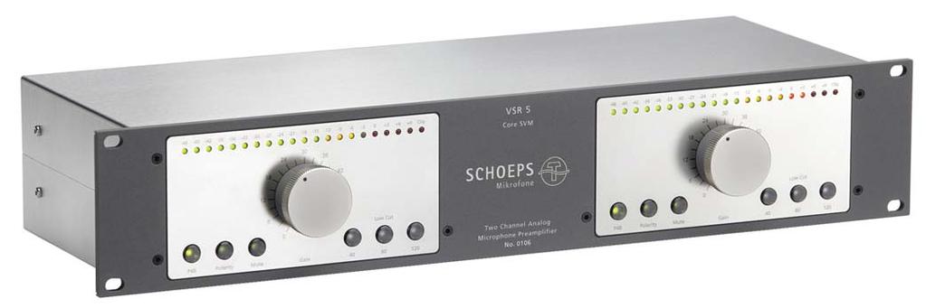
7 Operating Controls Front-panel features of the VSR 5 with phantom powering enabled and a microphone connected, normal polarity, outputs muted, and 80 Hz selected as the cutoff frequency of the low-cut filter. This function is carried out by means of high-quality relays rather than placing any additional electronic components in the signal path. Gain Control The gain of each channel can be set in 3 db steps from unity to 60 db by means of the 21-position rotary gain control on the front panel. The precision of this setting is within ±0.3 db throughout its entire range. Low-Cut Filters To remove inaudible frequencies as well as disturbing noise such as popping, wind or microphone handling noise without affecting the desired signal, the SCHOEPS VSR 5 offers three switch-selectable low-cut filters with 40 Hz, 80 Hz and 120 Hz cutoff frequencies. The currently active cutoff frequency is indicated by the bright white illumination of the corresponding switch. Only one filter per channel can be active at a time. The frequency can be changed simply by pressing the corresponding switch. Each filter can also be deactivated by pressing its Phantom powering is turned off. Phantom powering is turned on, but no microphone is connected. Phantom powering is turned on and a microphone is connected. 7

8 Operating Controls Note: During production, the reference level of the 0 db LED is set to +6 dbu. Here the 80-Hz low-cut filter has been activated. button a second time. The filter selection is stored when the preamplifier is turned off, and is set automatically the next time the unit is turned on. Level Indicator The signal level indicator of the VSR 5 consists of 21 LEDs including a Clip LED. The level is indicated in steps of 3 db. The range from -48 to -15 db is shown in green, the range from -12 to -3 db in yellow, and the LEDs for 0 to +9 db are red, as is the Clip LED. A full-wave DIN PPM peak detector drives the display with an attack time of <10 ms and a decay time of 0.5 seconds per 20 db. Clip Indicator The red Clip LED has a fixed reference voltage. It begins to blink at levels above ca. +20 dbu, thus giving a warning before there is any possible overload. Outputs The SCHOEPS VSR 5 is equipped with two separate electronically balanced XLR outputs per channel. The gold-plated XLR output sockets are on the rear panel of the unit. In accordance with international standards, the layout is: Pin 1 = Ground Pin 2 = (+) Phase Pin 3 = ( ) Phase Note: The VSR 5 has floating, servo-balanced outputs. Thus if either pin 2 or 3 is grounded, the output levels will remain the same as in balanced operation. VSR 5 output socket X balanced input Do not connect the plug connector's housing to pin 1. VSR 5 output socket X unbalanced input Do not connect the plug connector's housing to pin 1. In this case pin 3 must be connected to pin 1 (ground), since pins 2 and 3 of the output from the VSR 5 are floating. Connecting the inputs and outputs of the VSR 5 8
9 Notes on EMC, Ground-Lift Switch Notes on EMC (Electromagnetic Compatibility) This section is admittedly rather long in proportion to the rest of the manual. Please be assured that, as a rule, the VSR-5 will not have problems with interference even if you don't memorize all the details which we are about to present. However, in the rare event that a problem with hum or radio-frequency interference does occur, we want to offer enough information to be of real help. A summary of how to proceed: 1. Set the Ground Lift switch to the Hi-Z position. That setting will prevent interference in most circumstances, and is recommended as the default. 2. Use microphone cables that make no connection between the XLR-3M connector housing and pin 1. Only the shield of the cable should be connected with pin 1 at either end of the cable. For best results, use the SCHOEPS cable K EMC_U. 3. Whenever the outputs of the VSR 5 are connected to one or more items of other equipment, only one unit should have a direct connection between its circuit ground and AC safety ground. Thus, if necessary, a ground lift switch on one of the units should be set to the ground position. (This does not apply to battery-operated equipment, nor to AC-operated equipment that is completely isolated from the electrical safety ground and carries the symbol.) 4. Power all equipment that is connected to the VSR 5 from one common AC power outlet. Detailed description In the development of the VSR 5, emphasis was placed on first-rate audio characteristics but also on a corresponding degree of immunity to radio-frequency interference (RFI). Filters for this purpose have been built into the inputs and outputs, but these protective measures can reach their full effect only if suitable cables are used. To guarantee the best possible protection from RFI we recommend using special SCHOEPS XLR-3 microphone cable such as K EMC 10 U (10 meters) oder K EMC 20 U (20 meters). This cable is distinguished by: being RF-proof due to its high degree of shield coverage conduction of any RF picked up by the shield to the chassis of the unit to which the cable is connected, by means of condensers in the output plug not through the connection of pin 1 with the connector housing; this avoids ground loops small diameter robustness non-twisting (important when hanging microphones) flexibility even in cold weather Ground-Lift Switch In conventional XLR-3 cables pin 1 and the plug housing are often connected together. This can offer a certain amount of protection from electromagnetic fields. In that case the setting of the Ground-Lift switch is immaterial since it is bridged by the connection in the cable plug. But the connection of pin 1 with the connector housing can create ground loops which can cause hum when several pieces of equipment share the same protective AC ground. (What a ground loop is and what causes it is shown on the following page.) Thus the option exists to separate the circuit ground from the chassis ground by setting the Ground-Lift switch to the LIFT position. For this to have any effect, however, the connection in the XLR plug of the cable between pin 1 and the 9
10 Ground-Lift Switch Unit without ground-lift switch VSR 5 U Conductive chassis Conductive chassis Circuit ground 1 2 Connection by way of the house AC safety ground Circuit ground C* GND HI-Z LIFT Connector housing The red dashed line is a ground loop. As in the windings of a transformer, magnetic fields-- either from power supply transformers or due to differences in chassis potential among connected items of equipment cause current to flow at 50 or 60 Hz. Ground-lift switch * Bypass capacitor for RF; the SCHOEPS K EMC _U cable also has bypass capacitors in its XLR plug Cable shield The origin of ground loops I Hum current connector housing must be interrupted, and this can again lead to problems with RFI. To avoid both RFI and ground loops at the same time, we recommend the use of the SCHOEPS K EMC _ U cable. In the connectors of this cable there is no DC connection between pin 1 and the housing; thus no ground loops can occur. RFI on the other hand is conducted to chassis ground through condensers built into the plug connector. This provides RF protection despite the lack of a DC connection from pin 1 to the chassis. So that the Ground-Lift switch does not create a ground loop, do not set it to the GND position when this type of cable is being used. The HI-Z position of the Ground-Lift switch is designed to bridge the difference in ground potential among pieces of equipment that are connected to power outlets some distance apart, without causing hum problems. Safety is maintained by keeping the chassis of the VSR 5 connected to AC safety ground regardless of the Ground-Lift switch setting. Avoiding ground loops The greater the size of the loop encompassed by the relevant equipment, the greater the effective AC magnetic field radiated by transformers or electrical conductors, and the stronger the induced hum is likely to be. Thus to the extent possible, all interconnected equipment that uses three-wire AC power cords should be powered from the same outlet. This will minimize the ground loop area and thus the resulting hum. 10
11 Notes on EMC Cables among the various pieces of equipment should be arranged so that the loop they form has the smallest possible area. As a third tactic, the signal cables of all audio equipment should be kept as far as possible from sources of magnetic fields (transformers, high-current power cables). The Ground Lift switch will have no effect if pin 1 of the microphone cable is connected to its connector housing. In that case a ground loop will be created via the shield contact of the unit's input socket, since this contact is connected to the chassis and thus to the AC safety ground. If hum problems occur, the best approach is to reduce the extent of any ground loop. Should this not help, any existing connection between pin 1 and the plug connector housing of the microphone cable should be cut. But please be aware that doing this can lead to radio-frequency interference, especially if the RF is not bypassed to the chassis by way of a capacitor from pin 1 immediately at the input. c) if an item of equipment with a direct connection between its circuit ground and its AC safety ground is connected to the VSR 5; or d) double-insulated ( Class II ) equipment ( ), if a cable with an extra ground wire is connected. A further possible cause of hum Please note that strong hum can occur if the input of the VSR 5 is left open (i.e. neither a microphone nor any other item of equipment is connected to it) while the Ground-Lift switch is in the LIFT position. This hum does not represent a defect, but results from the fact that the circuit ground is not connected to the chassis under these conditions, which limits the ability of the chassis to act as a shield even though it is connected to the AC safety ground. The hum will disappear if any of the following occurs: a) if pin 1 of any cable connected to the VSR 5 is also connected to its connector housing; b) if the VSR 5's Ground-Lift switch is set to Ground ; 11
 Minimum current at which LEDs indicate a microphone at an input: 1.")
: 40 Hz, 80 Hz, 120 Hz at 12 db/oct. or off (see Fig. 2) THD+N at 1 khz: 0.")
, unweighted, RMS Fig. 2, Frequency response with 40, 80 and -130.6 dbu (-132.8 dbv), A, RMS*** 120 Hz cut-off frequency -117.4 dbu (-119.")
: 3 MHz 1 GHz, see Fig. 4 Max. output level: 28.")
 clipping LED lights up at +15 dbr Power supply: 94... 125 VAC / 185... 250 VAC, 50 60 Hz Power consumption: 10 VA Dimensions (19\", 2U): 485 mm (w) 60 mm (h) 195 mm (d) Weight: 4.")
12 Specifications Inputs: 2, balanced, electronically floating Phantom powering: +48 VDC (P 48*); can be switched off Resistances: kohms Maximum current: 10 ma (according to standards) Minimum current at which LEDs indicate a microphone at an input: 1.7 ma Input impedance: 8 kohms Input CMRR** at 60 db gain: > 90 db at 1 khz (for typical values see Fig. 1) > 80 db at 15 khz Max. input level: 25.4 dbu (23.2 dbv) at 0 db gain, f = 1 khz Fig. 1, Common-mode rejection ratio Gain adjustment: 0 db db in steps of 3 db Gain accuracy: ±0.3 db Low cut filters (-3 db): 40 Hz, 80 Hz, 120 Hz at 12 db/oct. or off (see Fig. 2) THD+N at 1 khz: % at 30 db gain and 27.5 dbu output level (1 db below clipping) into 100 kohm load (see Fig. 3) Noise (input terminated with 200 Ohms; gain: 60 db, referred to input): dbu ( dbv), unweighted, RMS Fig. 2, Frequency response with 40, 80 and dbu ( dbv), A, RMS*** 120 Hz cut-off frequency dbu ( dbv), CCIR-1k, Q-peak**** dbr dbr k 10k 40kHz k 10k 40kHz Frequency range (gain: 30 db): 12 Hz khz (±0.1 db) 2.5 Hz khz (-3 db) Inter-channel phase difference: 0.0 at 5 Hz 0.0 at 50 Hz 0.0 at 1 khz 0.0 at 10 khz at 200 khz Slew rate of the Core SVM : 10 V/µs at 30 db gain RF filter range (in- and outputs): 3 MHz 1 GHz, see Fig. 4 Max. output level: 28.5 dbu (26.3 dbv) Outputs: 2 2, balanced, electronically floating Output impedance: 50 Ohms Output CMRR*: ca. 60 db (20 Hz 20 khz) Meter range: -48 dbr dbr (adjustable) clipping LED lights up at +15 dbr Power supply: VAC / VAC, Hz Power consumption: 10 VA Dimensions (19", 2U): 485 mm (w) 60 mm (h) 195 mm (d) Weight: 4.70 kg, lbs Case: stainless steel, aluminum Front: gray Nextel finish; front panels: stainless steel dbr Fig. 3, 1 khz, gain= 30 db, 1 db below clipping dbr k 10k 40kHz 10MHz 100MHz 1GHz Fig. 4, noise floor and level of RF interference at 10 dbm and 80% AM modulation at the inputs 12
13 Safety Information Safety Information Please observe the following safety advice: Water, Liquids, Moisture Operation of the unit near water or other sources of liquids should be avoided. Please make certain that the unit cannot fall into liquids or that liquids cannot enter the openings in the unit's housing. The unit should not be operated in spaces with high humidity, especially condensing humidity. To preserve your warranty rights, all repairs during the warranty period should be carried out only by SCHOEPS or its authorized representatives. Caution: There is a risk of electrical shock if the unit is opened. Always disconnect from AC power first! Operating Voltage The unit may only be operated with the AC line voltages specified in these operating instructions ( VAC / VAC, Hz). Electrical Safety Ground Please make certain that the unit is connected to electrical safety ground in accordance with regulations. AC Power Cable Make certain that the AC power cable is in good condition. Arrange the AC power cable so that it will not be damaged and so that it does not cause accidents. The unit is shipped with a three-wire AC power cable with a German Schuko plug. On request a three-wire AC power cable for North American use can be provided instead. In some countries the unit must be used with a customer-provided AC power cable. Service / Repair None of the internal parts of this unit require maintenance. Any needed repairs should be carried out only by qualified service personnel. 13
14 Warranty, EMC, Declaration of Conformity Warranty We guarantee our products for a period of twenty-four months, except for batteries. The guarantee period begins on the date of purchase. Please provide your bill of sale in all cases as proof of guarantee; without it, repairs will be undertaken only at the owner's expense. We reserve the right to satisfy all warranty requirements regarding defects of workmanship or materials by means of repair or partial or complete replacement of the product, at our sole discretion. Excluded from this guarantee are defects due to misuse (e.g. incorrect operation; mechanical damage), abuse or Acts of God. This guarantee is nullified in the event of tampering by unauthorized persons or agencies. To secure your rights under this guarantee, send the product with proof of purchase and a precise description of the malfunction, at your expense, either to SCHOEPS (if you are a customer in Germany), or to our representative (if you are a customer outside of Germany). Prior to sending your defective product for repair, please contact your local dealer or distributor for instructions. In exceptional cases you can, by prior arrangement with SCHOEPS, send the product directly to us from a foreign country. However any return shipment must then be prepaid; this tends to cause delays, especially for non-warranty service. Full payment must be made before a repaired item can be returned to the customer. This guarantee does not affect any contractual agreements which may exist between the buyer and seller of the equipment. This guarantee is world-wide. Electromagnetic Compatibility (EMC) This equipment meets international specifications as described in the Declaration of Conformity below. It does not emit interference. It can be used in environments in which interference exists, even if that reduces its effectiveness for its intended use. That is, the unit's functioning may be affected in the worst case by electrical, magnetic or electromagnetic fields, but it will not be damaged. Operation of this equipment in surroundings with high electromagnetic field strengths (e.g. near transmitters) should be avoided. Declaration of Conformity CE-Mark The CE-mark guarantees that all products conform to relevant standards approved by the European Community. The products described in this User Guide comply with current, relevant standards when used with cables from SCHOEPS. Relevant directives: EMC Directive: 89/336/EEC, amended by 92/31/EEC and 93/68/EEC Relevant standards: EN , -2 and those which are referred to by them. 14
15 15
16 Subject to change without notice. Not responsible for errors or omissions SCHOEPS GmbH Spitalstraße 20 D Karlsruhe (Durlach) Tel: +49 (0) Fax: +49 (0) Schall Technik
Amplifier Series BASIC. Installation & Operations Manual
 Amplifier Series BASIC Installation & Operations Manual Bittner-Audio 200 Power Amplifier Series BASIC Bittner - Audio September 200 200 Bittner-Audio. All Rights Reserved. Bittner-Audio reserves specification
KeyPre KP6 - Electronic Instrument Preamplifier
 ! USE ONLY WITH 250V FUSE KeyPre KP6 - Electronic Instrument Preamplifier USER S GUIDE 0 10dB 0 10dB 0 10dB 0 10dB 0dB 10dB 0 10dB AVEDIS AUDIO E L E C T R O N I C S AC INPUT 100-240VAC 50/60 Hz 1.1" 1.225"
4 Channel Frequency Conscious Noise Gate. Operation Manual
 4 Channel Frequency Conscious Noise Gate Operation Manual June 2005 This page has been left intentionally blank for your notes Page 2 CONTENTS 1.0 OVERVIEW 4 2.0 DESCRIPTION OF CONTROLS 5-7 2.1 Bypass
SI-125 Power Amplifier Manual 6205 Kestrel Road; Mississauga, Ontario; Canada; L5T 2A1 November 2016, Rev 0.5
 SI-125 Power Amplifier Manual 6205 Kestrel Road; Mississauga, Ontario; Canada; L5T 2A1 November 2016, Rev 0.5 Phone: (905) 564-0801 Fax: (905) 564-0806 www.telecor.com E:\T2-108\T2-M108-ABC\T2-M108-B.doc/AD
DPA74/154 AUDAC PROFESSIONAL AUDIO EQUIPMENT. DPA74/154 Quad Channel Class-D Amplifier. User Manual & Installation Guide
 DPA74/154 PROFESSIONAL AUDIO EQUIPMENT DPA74/154 Quad Channel Class-D Amplifier AUDAC User Manual & Installation Guide AUDAC PROFESSIONAL AUDIO EQUIPMENT User Manual & Installation Guide AUDAC http://www.audac.eu
441 DUAL CHANNEL 15 BAND 2/3 OCTAVE GRAPHIC EQUALIZER 451 SINGLE CHANNEL 31 BAND 1/3 OCTAVE GRAPHIC EQUALIZER
 441 DUAL CHANNEL 15 BAND 2/3 OCTAVE GRAPHIC EQUALIZER 451 SINGLE CHANNEL 31 BAND 1/3 OCTAVE GRAPHIC EQUALIZER 455 DUAL CHANNEL 31 BAND 1/3 OCTAVE GRAPHIC EQUALIZER The new ART 400 Series of Precision Graphic
Power Amplifier D2 D3 D4 D5 AUDAC PROFESSIONAL AUDIO EQUIPMENT. Dual Channel Power Amplifier D2 D3 D4 D5. User Manual & Installation Guide
 Power Amplifier D2 D3 D4 D5 AUDAC PROFESSIONAL AUDIO EQUIPMENT Dual Channel Power Amplifier D2 D3 D4 D5 User Manual & Installation Guide AUDAC PROFESSIONAL AUDIO EQUIPMENT User Manual & Installation Guide
Model 7000 Low Noise Differential Preamplifier
 Model 7000 Low Noise Differential Preamplifier Operating Manual Service and Warranty Krohn-Hite Instruments are designed and manufactured in accordance with sound engineering practices and should give
T L Audio CRIMSON SERIES. User Manual EQ-3011 EQUALISER. Tony Larking Professional Sales Limited, Letchworth, England.
 T L Audio CRIMSON SERIES User Manual EQ-3011 EQUALISER Tony Larking Professional Sales Limited, Letchworth, England. Tel: 01462 490600. International +44 1462 490600. Fax: 01462 490700. International +44
ADA416-XLR DISTRIBUTION AMPLIFIERS OPERATING AND MAINTENANCE MANUAL
 ADA416-XLR DISTRIBUTION AMPLIFIERS OPERATING AND MAINTENANCE MANUAL Copyright 2015, ATI Audio Inc. DESCRIPTION Your ADA416-XLR provides four independent one-in by four-out circuit groups. A four-output
model 101 single channel microphone preamplifier owner s manual Rev C
 2434 30th street, boulder, CO 80306-0204 USA tel 303.443.7454 fax 303.444.4634 info@gracedesign.com / www.gracedesign.com single channel microphone preamplifier Rev C all contents Grace Design/ Lunatec
HQ-31 HQ-15 USER S GUIDE SINGLE CHANNEL 31 BAND 1/3 OCTAVE GRAPHIC EQUALIZER DUAL CHANNEL 15 BAND 2/3 OCTAVE GRAPHIC EQUALIZER
 HQ-31 SINGLE CHANNEL 31 BAND 1/3 OCTAVE GRAPHIC EQUALIZER HQ-15 DUAL CHANNEL 15 BAND 2/3 OCTAVE GRAPHIC EQUALIZER USER S GUIDE GENERAL INFORMATION SINGLE CHANNEL 31 BAND 1/3 OCTAVE GRAPHIC EQUALIZER WITH
SR Series Crossovers. Owner s Manual SR 823 SR 834. A Harman International Company
 SR Series Crossovers Owner s Manual SR 823 SR 834 A Harman International Company Warning For your protection, please read the following: These symbols are internationally accepted symbols that warn of
PA WATT PORTABLE PA SYSTEM PRODUCT MANUAL
 PA-5150 5 150-WATT PORTABLE PA SYSTEM PRODUCT MANUAL THANK YOU FOR CHOOSING POLSEN. The Polsen PA-5150 is an active PA system that s ideal for solo performers or vocalists. It can be used as a PA system
T L Audio CRIMSON SERIES. User Manual EQ-3012 PARAMETRIC EQUALISER. Tony Larking Professional Sales Limited, Letchworth, England.
 T L Audio CRIMSON SERIES User Manual EQ-3012 PARAMETRIC EQUALISER Tony Larking Professional Sales Limited, Letchworth, England. Tel: 01462 490600. International +44 1462 490600. Fax: 01462 490700. International
MZ2 HEADPHONE AMPLIFIER, PREAMP, & STEREO AMPLIFIER USER GUIDE
 MZ2 HEADPHONE AMPLIFIER, PREAMP, & STEREO AMPLIFIER USER GUIDE Linear Tube Audio Takoma Park, MD, USA WARNING: For safety, the cover of this amplifier should be secured at all times. DC voltages as high
DUAL LEVELAR. Two Channel Tube Compressor/Leveling Amplifier
 DUAL LEVELAR Two Channel Tube Compressor/Leveling Amplifier USER S GUIDE Introduction Thank you for purchasing the Dual Levelar and congratulations! You now own one of the most sophisticated pieces of
MP-1 Microphone Preamplifier User Guide and Technical Information
 SOUND DEVICES MP-1 Microphone Preamplifier Voice 608.524.0625 Fax 608 524.0655 www.sounddevices.com General Description The MP-1 from Sound Devices is a portable, battery-powered microphone preamplifier
Boulder W Class A Stereo Power Amplifier
 Boulder 2060 600 W Class A Stereo Power Amplifier Owners Manual V1.0 10/10/97 TABLE OF CONTENTS GETTING STARTED Placement of the 2050 Power amplifier......................................... 1-1 Connecting
audionet PAM G2 User s Manual Phono Preamplifier for MC / MM
 audionet PAM G2 Phono Preamplifier for MC / MM User s Manual 1 2 Contents 1 Preface... 5 1.1 Included... 6 1.2 Transport... 6 2 Overview front panel... 7 3 Overview back panel... 8 4 Installation and power
MC450/MC650 (MC750) OPERATING INSTRUCTIONS
 OPERATING INSTRUCTIONS") MC450/MC650 (MC750) OPERATING INSTRUCTIONS MC 2 AUDIO Ltd., Units 6 & 7 Kingsgate, Heathpark Industrial Estate, HONITON, Devon EX14 1YG England Tel: ++(0)1404.44633 Fax: ++(0)1404.44660 www.mc2-audio.co.uk
MC450/MC650 (MC750) OPERATING INSTRUCTIONS MC 2 AUDIO Ltd., Units 6 & 7 Kingsgate, Heathpark Industrial Estate, HONITON, Devon EX14 1YG England Tel: ++(0)1404.44633 Fax: ++(0)1404.44660 www.mc2-audio.co.uk
TransX TWO CHANNEL TRANSFORMER ISOLATED DISCRETE TRANSISTOR PREAMP USER'S MANUAL
 TransX TWO CHANNEL TRANSFORMER ISOLATED DISCRETE TRANSISTOR PREAMP USER'S MANUAL IMPORTANT SAFETY INSTRUCTIONS READ FIRST This symbol, whenever it appears, alerts you to the presence of uninsulated dangerous
AELIUS YPSILON POWER AMPLIFIER. OWNERS MANUAL V1 01/01/20010 All rights reserved
 AELIUS YPSILON POWER AMPLIFIER OWNERS MANUAL V1 01/01/20010 All rights reserved INTRODUCTION Thank you for trusting YPSILON ELECTRONICS. We assure you that you have made an excellent purchase. Your amplifier
T L Audio. User Manual EQ1 VALVE EQUALISER. Tony Larking Professional Sales Limited, Letchworth, England.
 T L Audio User Manual EQ1 VALVE EQUALISER Tony Larking Professional Sales Limited, Letchworth, England. Tel: 01462 490600, International +44 1462 490600. Fax: 01462 490700, International +44 1462 490700.
Boulder 810 Preamplifier
 Boulder 810 Preamplifier Owners Manual 6/8/06 Boulder Amplifiers, Inc. 3235 Prairie Ave. Boulder, CO 80301 www.boulderamp.com APPENDIX RECORDING BOULDER LINK PROGRAMMING REMOTE CONTROL OPERATION GETTING
S 275 Stereo Power Amplifier THE LEADER IN AUDIO ENGINEERING. Instructions for Use. Owner s Reference
 THE LEADER IN AUDIO ENGINEERING S 275 Stereo Power Amplifier Instructions for Use Owner s Reference Introduction Thank you for your purchase of the Krell S-275 Stereo Power Amplifier. This configurable
Back to Operator Manual Index MX50 OPERATORS MANUAL. DRAWMER MX50 Dual De-Esser SAFETY CONSIDERATIONS
 1 of 6 1/31/2005 2:44 PM Back to Operator Manual Index MX50 OPERATORS MANUAL : SAFETY CONSIDERATIONS INTRODUCTION INSTALLATION CONTROL DESCRIPTION OPERATION TECHNICAL SPECIFICATIONS DRAWMER MX50 Dual De-Esser
Q44/Q66 PROFESSIONAL AMPLIFIER OWNER S MANUAL
 Q44/Q66 PROFESSIONAL AMPLIFIER OWNER S MANUAL IMPORTANT SAFETY INSTRUCTIONS The lightning flash with arrowhead symbol, within an equilateral triangle is intended to alert the user to the presence of uninsulated
Owner s manual. SDA 2175 Semi Digital Amplifier
 Owner s manual SDA 2175 Semi Digital Amplifier 2 Table of Contents Operating Voltage 4 Unpacking the SDA 2175 4 Serial Number Registration 4 Introduction 5 Accessories 6 Front Panel 7 - Controls 7 Rear
audionet amp II G2 Owner's Manual Mono - Amplifier
 audionet amp II G2 Mono - Amplifier Owner's Manual Owner's manual The Audionet-Team would like to congratulate you to purchasing the Audionet AMP II G2! Your Audionet AMP II G2 is designed for absolutely
Kaskode One Phono Preamplifier Owner s Manual
 Kaskode One Phono Preamplifier Owner s Manual www.bandwidthaudio.com sales@bandwidthaudio.com WARNING Configuration of the Kaskode One will require removing the cover of the unit. Before removing the cover
TOA PROFESSIONAL POWER AMP
 Operating Instruction Manual TOA PROFESSIONAL POWER AMP Model P-150M, P-300M TOA ELECTRIC CO, LTD. KOBE, JAPAN Contents Precautions... 2 General Description... 2 Features... 3 Specifications... 4~5 Performance
TABLE OF CONTENTS. 1) Introduction 2. 2) Unpacking your preamplifier 2. 3) Installing the preamp into your system 3
 Introduction 2. 2) Unpacking your preamplifier 2. 3) Installing the preamp into your system 3") TABLE OF CONTENTS 1) Introduction 2 2) Unpacking your preamplifier 2 3) Installing the preamp into your system 3 4) Operation of your preamplifier 6 5) Troubleshooting 8 6) Registration of your preamplifier
TABLE OF CONTENTS 1) Introduction 2 2) Unpacking your preamplifier 2 3) Installing the preamp into your system 3 4) Operation of your preamplifier 6 5) Troubleshooting 8 6) Registration of your preamplifier
USER MANUAL. GOLDMUND TELOS 1000 Universal Power Amplifier
 USER MANUAL GOLDMUND TELOS 1000 Universal Power Amplifier Thank you for purchasing the GOLDMUND TELOS 1000. You have acquired the best Universal Power Amplifier ever made for professional and domestic
USER MANUAL GOLDMUND TELOS 600 Universal Power Amplifier
 USER MANUAL GOLDMUND TELOS 600 Universal Power Amplifier Congratulations. Thank you for purchasing the GOLDMUND TELOS 600. You have acquired the best Universal Power Amplifier ever made for professional
R-Series R235LS 2-Channel Power Amplifier with Local Source Switching
 R-Series R235LS 2-Channel Power Amplifier with Local Source Switching User s Manual On Off R235LS POWER A MPLIFIER IMPORTANT SAFEGUARDS WARNING TO REDUCE THE RISK OF FIRE OR ELECTRIC SHOCK, DO NOT EXPOSE
USER MANUAL GOLDMUND MIMESIS 29M Millennium Edition Power Amplifier
 USER MANUAL GOLDMUND MIMESIS 29M Millennium Edition Power Amplifier CONGRATULATIONS Thank you for purchasing the Goldmund Mimesis 29M Millennium Edition. You have acquired the best Analogue Power Amplifier
CONCERT-1 CONCERT-2. Instrument DI. The World s Finest Transformers
 Owner s Manual CONCERT-1 CONCERT-2 Instrument DI Jensen Transformers Inc 9304 Deering Ave. Chatsworth, CA 91311 Tel: 818-374-5857 Email: info@jensen-transformers.com www.jensen-transformers.com Concert-1
The elysia team wishes you great delight and compression deluxe with your new mpressor 500.
 mpressor 500 The compressor from the future The mpressor 500 brings the heritage of our extremely powerful rack mount mpressor into the 500 series format. Like its bigger brother, the mpressor 500 combines
ELECTRONIC LOUDSPEAKER SYSTEM CONTROLLER TX3 USER MANUAL
 ELECTRONIC LOUDSPEAKER SYSTEM CONTROLLER TX3 USER MANUAL Contents INTRODUCTION 2 OPERATING INSTRUCTIONS 2 Preliminary advice and information 2 Input connections 3 Output connections 3 Operation 4 TECHNICAL
3050 Stereo Power Amplifier
 3050 Stereo Power Amplifier Owners Manual 10/26/2016 Boulder Amplifiers, Inc. 255 Taylor Ave. Louisville, CO 80027 (303) 449-8220 www.boulderamp.com Fault Conditions Boulderlink Appendix Remote Control
MANUAL. Champ - 4. Professional quad power amplifier
 MANUAL Champ - 4 Professional quad power amplifier INFO@APART-AUDIO.COM Safety First! Caution: hot and sharp surfaces! This professional device needs to be installed by qualified personnel only. Please
BlueTube. Two Channel Microphone / Instrument Tube Preamplifier. User s Manual
 BlueTube Two Channel Microphone / Instrument Tube Preamplifier User s Manual Blue Tube TWO CHANNEL MICROPHONE/INSTRUMENT TUBE PRE-AMPLIFIER USERS MANUAL Version 1.0 2000, PreSonus Audio Electronics, Incorporated.
L-7000 LINE STAGE PREAMPLIFIER OWNER S MANUAL
 L-7000 LINE STAGE PREAMPLIFIER OWNER S MANUAL L-7000 LINE STAGE PREAMPLIFIER Thank you for purchasing this Allnic Audio L-7000 Line Stage Preamplifier. We are certain your trust in Allnic Audio and Allnic
ECI 6D. Balanced Integrated Amplifier. Owner's Manual. (with a built-in DAC) ENGLISH
 ENGLISH") ECI 6D Balanced Integrated Amplifier (with a built-in DAC) Owner's Manual EN ENGLISH Unpacking the ECI 6D Immediately upon receipt of the ECI 6D, inspect the carton for possible damage during shipment.
ECI 6D Balanced Integrated Amplifier (with a built-in DAC) Owner's Manual EN ENGLISH Unpacking the ECI 6D Immediately upon receipt of the ECI 6D, inspect the carton for possible damage during shipment.
S 1500 MULTI-CHANNEL INSTRUCTIONS FOR USE AMPLIFIER. Owner s Reference
 S 1500 MULTI-CHANNEL AMPLIFIER Owner s Reference INSTRUCTIONS FOR USE S 1500 Multi-channel Amplifier Instructions for Use v 07.0 CONTACT INFORMATION Krell Industries, Inc. 45 Connair Road Orange, CT 06477-3650
MUSICA C101 preamplifier
 User manual MUSICA C101 preamplifier 1 Thank you of purchasing this EamLab product. Who are dedicated to the policy of creating the highest quality audio components, are proud to introduce. You can be
MODEL 3 MONO AMPLIFIER OWNER S MANUAL
 MODEL 3 MONO AMPLIFIER OWNER S MANUAL TABLE OF CONTENTS Introduction Features Unpacking Instructions Installation * Space requirements * A.C. connections Input Impedance Selection Adjustable Gain Signal
Boulder W Mono Power Amplifier
 Boulder 1050 500 W Mono Power Amplifier Owners Manual 4/11/04 Boulder Amplifiers, Inc. 3235 Prairie Ave. Boulder, CO 80301 www.boulderamp.com APPENDIX BOULDER LINK REMOTE CONTROL OPERATION GETTING STARTED
USER S MANUAL. version , PreSonus Audio Electronics, Incorporated. All rights reserved.
 USER S MANUAL version 1.0 2005, PreSonus Audio Electronics, Incorporated. All rights reserved. WARRANTY PreSonus Limited Warranty PreSonus Audio Electronics Inc. warrants this product to be free of defects
ELECTRICAL AUDIO EApreq
 ELECTRICAL AUDIO EApreq The EAPreq is a two channel transformer-based microphone preamp/equalizer. The preamp is designed to allow the character of the input transformer to color the sound with very little
DA208 & DA416 DISTRIBUTION AMPLIFIERS OPERATING AND MAINTENANCE MANUAL
 DA208 & DA416 DISTRIBUTION AMPLIFIERS OPERATING AND MAINTENANCE MANUAL Copyright 2011, ATI Audio Inc. DESCRIPTION Your DA208 or DA416 provides two (DA208) or four (DA416) independent one-in by four-out
User Instructions. Model PS-2001L. Power Supply. Model SPS Power Supply. Audiocom Intercom Systems Rev. A, 4/2001.
 User Instructions PS-00L Model PS-00L Power Supply SPS-00 Volume Model SPS-00 Power Supply Audiocom Intercom Systems 950-7699-000 Rev. A, /00 FCC Statement This equipment uses, and can radiate radio frequency
SCM-660 USER S GUIDE. Table of Contents:
 Table of Contents: USER S GUIDE Introduction... 2 Overview... 3 Precautions...4 Mounting the Microphone... 5 Selectable Polar Pattern Switch...6 High-Pass Filter... 7 Attenuation Pad... 7 Connecting the
KRAMER ELECTRONICS LTD. USER MANUAL MODEL: 912 Power Amplifier. P/N: Rev 2
 KRAMER ELECTRONICS LTD. USER MANUAL MODEL: 912 Power Amplifier P/N: 2900-000684 Rev 2 Contents 1 Introduction 1 2 Getting Started 2 2.1 Achieving the Best Performance 2 3 Overview 3 3.1 Defining the 912
EQ-AMP60 60W Mixer Amplifier
 EQ-AMP60 60W Mixer Amplifier Instruction Manual 4091 AMTC Center Drive Clearwater, FL 33764-6976 (727)531-3105 (727)531-3965 www.amtc.com Features 1. MIC 1 input with front- and rear-panel connectors 2.
VENUE Full Isolation D.I.
 VENUE Full Isolation D.I. USER S GUIDE www.lrbaggs.com INTRODUCTION Thank you for purchasing our Venue D.I. This is the first all-discrete acoustic guitar preamp to combine a transformer-coupled D.I. output
Solutions. Alpha. Manual English
 Acoustic Solutions Alpha Manual English 1 Acoustic Solutions Alpha Operating Manual Contents: 1. Introduction 2. Safety Precautions 3. Controls and Connections 4. Operation Summary 5. Technical Data 6.
ALLNIC AUDIO L 1500 LINE STAGE PREAMPLIFIER
 ALLNIC AUDIO L 1500 LINE STAGE PREAMPLIFIER OWNER S MANUAL ALLNIC AUDIO L-1500 LINE STAGE PREAMPLIFIER Thank you for purchasing this Allnic Audio L 1500 Line Stage Preamplifier. We are certain your trust
USER MANUAL. GOLDMUND Metis 5 Analog Integrated Amplifier
 USER MANUAL GOLDMUND Metis 5 Analog Integrated Amplifier Thank you for purchasing the Goldmund METIS 5 Analog Integrated Amplifier. The Goldmund Metis line amplifiers fully incorporate the technological
STEREO POWER AMPLIFIER OWNER MANUAL PR-150 DESIGNED IN U.K. PDF created with FinePrint pdffactory trial version
 STEREO POWER AMPLIFIER OWNER MANUAL PR-150 DESIGNED IN U.K. INTRODUCTION Congratulations on your purchase of MA PR-150 Stereo Power Amplifier. The performance of PR-150 is perfect for any audio application,
1160 Stereo Power Amplifier
 1160 Stereo Power Amplifier 03/01/2018 Rev. 1.0 P/N: 91055 Boulder Amplifiers, Inc. 255 S. Taylor Ave. Louisville, CO 80027 (303) 449-8220 www.boulderamp.com About About Boulder Amplifiers, Inc. Boulder
AEA TRP2 OWNER S MANUAL THE ORIGINAL 2-CHANNEL RIBBON PREAMP
 AEA TRP2 OWNER S MANUAL THE ORIGINAL 2-CHANNEL RIBBON PREAMP WELCOME Congratulations on your purchase of the TRP2 preamp and welcome to the AEA family. AEA takes sonic integrity seriously and have created
DL102 Counter Loop Amplifier
 DL102 Counter Loop Amplifier USER MANUAL MAN 234A Contents Overview...3 System Includes...3 Maintenance and Recycling Instructions...3 Safety Information...4 Quick Setup...5 Setup...6 Loop Amplifier...6
USER MANUAL. GOLDMUND MIMESIS 27.5 Analog Preamplifier
 USER MANUAL GOLDMUND MIMESIS 27.5 Analog Preamplifier Thank you for purchasing the GOLDMUND MIMESIS 27.5 Analogue Preamplifier. Please take some time to read this manual. It may provide you with useful
USER MANUAL. GOLDMUND TELOS 2500 NextGen Universal Power Amplifier
 USER MANUAL GOLDMUND TELOS 2500 NextGen Universal Power Amplifier Thank you for purchasing the GOLDMUND TELOS 2500 NextGen. You have acquired the best Universal Power Amplifier ever made for professional
EC 4.6 REMOTE CONTROLLED BALANCED LINE PREAMPLIFIER
 EC 4.6 REMOTE CONTROLLED BALANCED LINE PREAMPLIFIER Owner s Manual WARNING: To reduce risk of fire or electric shock, do not expose this appliance to rain or moisture. Verify line voltage before use. Do
Q-Tech. Q-Tech Commercial Series QTA 1360P/1480P Power Amplifiers. User Manual
 Q-Tech Power Amplifiers WARNING THIS APPLIANCE MUST BE EARTHED General Installation DO NOT run unbalanced high impedance microphone cables near mains, data, telephone or 70/100V line cables. DO NOT run
DPA-1200 ORDERCODE D4180 DPA-2400 ORDERCODE D4181 DPA-3400 ORDERCODE D4182
 Digital DPA-1200 DPA-2400 DPA-3400 ORDERCODE D4180 ORDERCODE D4181 ORDERCODE D4182 Congratulations! You have bought a great, innovative product from DAP Audio. The Dap Audio Vintage Digital Power Series
PM7400MKII. Instruction manual
 PM7400MKII Instruction manual PM7400MKII Instruction manual 3 PM7400MKII Manual 4 Pre-amplifier Safety first! Caution: hot and sharp surfaces! This professional device needs to be installed by qualified
Summit Audio Model EQP-200B Dual Program Equalizer Operating Manual
 Summit Audio Model EQP-200B Dual Program Equalizer Operating Manual IMPORTANT!: CAREFULLY READ THE ENTIRE INSTRUCTION MANUAL BEFORE HOOKUP OR OPERATION OF THE EQP-200B. WARNING!: HIGH VOLTAGE. THIS UNIT
audionet AMP 1 V2 User s Manual Stereo - Amplifier
 audionet AMP 1 V2 Stereo - Amplifier User s Manual 1 2 Contents 1 Preface... 4 1.1 Included... 5 1.2 Transport... 5 2 Overview control elements... 6 2.1 Front panel... 6 3 Overview connections... 7 3.1
User's Guide QuadMic
 User's Guide QuadMic Portable Professional Mic Preamp 4-channel Microphone / Line Preamp with Line Outputs Universal Power Supply Input Contents 1 Introduction...3 2 Package Contents...3 3 Brief Description
USER MANUAL. GOLDMUND METIS 2 Analog Preamplifier
 USER MANUAL GOLDMUND METIS 2 Analog Preamplifier Thank you for purchasing the GOLDMUND METIS 2 Analog Preamplifier. The Goldmund Metis line amplifiers fully incorporate the technological expertise developed
POWER AMPLIFIER. Owner s Manual Mode d emploi Bedienungsanleitung Manual de instrucciónes CLIP SIGNAL TEMP PROTECTION POWER
 POWER AMPLIFIER Owner s Manual Mode d emploi Bedienungsanleitung Manual de instrucciónes TEMP PROTECTION POWER A CLIP SIGNAL B ON OFF M Introduction Thank you for purchasing a Yamaha C450/320/160 series
PROFESSIONAL POWER AMPLIFIERS. User Instructions. American DJ V3000 LIMITER. American DJ LIMITER I LIMITER. ON channel 2
 & PROFESSIONAL POWER AMPLIFIERS User Instructions American DJ SIG 20 10 5 CLIP PROTECT POWER PROTECT CLIP 5 10 20 SIG PROformer Series V3000 channel 1 ON ON channel 2 I O Professional Stereo Amplifier
Video/Audio Transmission System Series VA700. (formerly Series DVL4A)
") Video/Audio Transmission System Series VA700 (formerly Series DVL4A) November 2000 1 VIDEO/AUDIO TRANSMISSION SYSTEM INSTRUCTION MANUAL SERIES VA700 & VA700M General The Series VA700 is a transmission
Video/Audio Transmission System Series VA700 (formerly Series DVL4A) November 2000 1 VIDEO/AUDIO TRANSMISSION SYSTEM INSTRUCTION MANUAL SERIES VA700 & VA700M General The Series VA700 is a transmission
ALIGN SERIES ACTIVE DI USER S GUIDE
 ALIGN SERIES ACTIVE DI USER S GUIDE INTRODUCTION Building upon decades of experience creating studio-quality gear for the stage, the Align Active DI is the embodiment of LR Baggs engineering at its highest
CLASS A DUAL TRANSFORMER COMPRESSOR OWNER S MANUAL
 LIMINATOR CLASS A DUAL TRANSFORMER COMPRESSOR OWNER S MANUAL TABLE OF CONTENTS SECTION PAGE INTRODUCTION 2 INSTALLATION 3 FRONT PANEL CONTROLS 4 OPERATION 5 SPECIFICATIONS 7 WARRANTY AND REGISTRATION 8-1
REVAMP2600 Instruction manual
 REVAMP2600 Instruction manual REVAMP2600 Instruction manual 3 REVAMP2600 MANUAL 4 PROFESSIONAL POWER AMPLIFIER Safety first! Caution! This professional device needs to be installed by qualified personnel
T L Audio INDIGO SERIES. User Manual VP-2051 VALVE VOICE PROCESSOR. Tony Larking Professional Sales Limited, Letchworth, England.
 T L Audio INDIGO SERIES User Manual VP-2051 VALVE VOICE PROCESSOR Tony Larking Professional Sales Limited, Letchworth, England. Tel: 01462 490600. International +44 1462 490600. Fax: 01462 490700. International
EPA152/252/502. User Manual.
 EPA152/252/502 User Manual www.audac.eu ADDITIONAL INFORMATION This manual is put together with much care, and is as complete as could be on the publication date. However, updates on the specifications,
Owner s Manual B 300 B 600 B 900 B 1200 B 1500 B 902 B 1202 B 1802 B300 B1802
 Owner s Manual B 300 B 600 B 900 B 1200 B 1500 B300 B 902 B 1202 B 1802 B1802 WARNING B 300 / B 600 / B 900 / B 1200 / B 1500 / B 902 / B 1202 / B 1802 Table of Contents Table of Contents Introduction
TOA 500 SERIES MIXER POWER AMPLIFIER
 TOA 500 SERIES MIXER POWER AMPLIFIER Operation Instruction Manual A-503A A-506A A-512A Features General Description 1. High quality design and construction. 2. Full frequency response: 50-15,000Hz, ±3dB.
Model 901 HEADPHONE AMPLIFIER OWNERS MANUAL. PO Box 204 Boulder, CO tel: fax:
 Model 901 HEADPHONE AMPLIFIER OWNERS MANUAL PO Box 204 Boulder, CO 80306 tel: 303.443.7454 fax: 303.444.4634 email: info@gracedesign.com web: www.gracedesign.com Revision A November, 2001 Copyright 2001,
The ART SLA-2 Studio Linear Amplifier
 TABLE OF CONTENTS The ART SLA-2 Studio Linear Amplifier Safety Precautions... 2-3 Introduction... 4 Installation... 5 AC Power Hookup... 5 Audio Connections... 5 Security Cover... 6 Controls and Indicators...
SAGA PRO SERIES STEREO POWER AMPLIFIER OPERATION MANUAL
 SAGA PRO SERIES STEREO POWER AMPLIFIER OPERATION MANUAL INSTALLATION Use care in unpacking the amplifier, and be sure to save the carton and packing materials so that you can use them for moving, storing,
AAA Balanced / Unbalanced Line Audio Interface Amplifiers. User Manual. I.R.T. Communications Pty Ltd
 Balanced / Unbalanced Line Audio Interface Amplifiers User Manual Revision 02 BALANCED / UNBALANCED LINE AUDIO INTERFACE AMPLIFIERS Revision History: Revision Date By Change Description Applicable to:
Opus 21 s80 Integrated Amplifier Owner's Manual
 Opus 21 s80 Integrated Amplifier Owner's Manual r e s o l u t i o n From all of us at Resolution Audio, thank you for choosing the Opus 21 s80 amplifier. We went to great lengths to design and produce
1. FEATURES ON THE CONTROL PANEL FEATURES ON THE BACK PANEL General Options SAFETY INFORMATION...
 LOGIBIT 1200 MANUAL Table of Contents TABLE OF CONTENTS 1. FEATURES ON THE CONTROL PANEL... 1 2. MENU STRUCTURE... 2 2.1 Function keys... 2 2.2 Menu points... 2 2.3 Illustration of menu structure... 5
2BSST POWER AMPLIFIER OWNER S MANUAL
 2BSST POWER AMPLIFIER OWNER S MANUAL IMPORTANT SAFETY INSTRUCTIONS The lightning flash with arrowhead symbol within an equilateral triangle, is intended to alert the user to the presence of un-insulated
OPERATION & SERVICE MANUAL FOR FC 110 AC POWER SOURCE
 OPERATION & SERVICE MANUAL FOR FC 100 SERIES AC POWER SOURCE FC 110 AC POWER SOURCE VERSION 1.3, April 2001. copyright reserved. DWG No. FC00001 TABLE OF CONTENTS CHAPTER 1 INTRODUCTION... 1 1.1 GENERAL...
User Manual. ia480x Power amplifier
 User Manual ia480x Power amplifier Safety instructions When using this electronic device, basic precautions should always be taken, including the following: 1 Read all instructions before using the product.
User Manual VOLUME PTT 1 MIC/LINE 2 MIC/LINE 3 MIC/LINE 4 MIC/LINE 5 MIC/LINE 6 MIC/LINE 7 MIC/LINE 8 MIC/LINE 9 MIC/LINE 10 LEVEL LEVEL TREBLE 6 MIC
 + 7 54 ZM 0 Audio Mixer User Manual www.cleveracoustics.co.uk CAUTION RISK OF ELECTRIC SHOCK DO NOT OPEN. NO USER SERVICABLE PARTS INSIDE WARNING: TO REDUCE THE RISK OF FIRE OR ELECTRIC SHOCK. DO NOT EXPOSE
OWNER S MANUAL CPS 1 / CPS 2 CONTRACTOR PRECISION SERIES
 OWNER S MANUAL CPS 1 / CPS 2 CONTRACTOR PRECISION SERIES CONTENTS Introduction................................................................... 9 Front Panel...................................................................
PA240 ORDERCODE D6113
 PA240 ORDERCODE D6113 Congratulations! You have bought a great, innovative product from DAP Audio. The Dap Audio PA240 brings excitement to any venue. Whether you want simple plug-&-play action or a sophisticated
PROFESSIONAL POWER AMP
 Operating Instruction Manual PROFESSIONAL POWER AMP Model P-75D, P-150D, P-300D P-75D P-150D P-300D TOA Corporation KOBE, JAPAN Contents Precautions... 1 General Description... 2 Features... 2~ 3 Specifications...
Professional Power Amplifier
 SERVICE FOR YOURCBU PRODUCT (International) For service, please contact the CBU distributor in your country through the dealer from whom you purchased this product. DO NOT ATTEMPT TO SERVICE THIS UNIT
Trace Elliot Elf Bass Instrument Amplifier
 Trace Elliot Elf Bass Instrument Amplifier Owner s Manual FCC Compliancy Statement This device complies with Part 15 of the FCC rules. Operation is subject to the following two conditions: (1) this device
SS-4.2 / SS-6.2. Instruction Manual. Impedance Matching Speaker Selector
 -4.2 / -6.2 Instruction Manual Impedance Matching peaker elector Introduction Thank you for purchasing a quality ussound product. The ussound -4.2 and -6.2 speaker selectors permit either four or six pair