Increasing Automotive Safety with 77/79 GHz Radar Solutions for ADAS Applications
|
|
|
- Roland Mosley
- 6 years ago
- Views:
Transcription

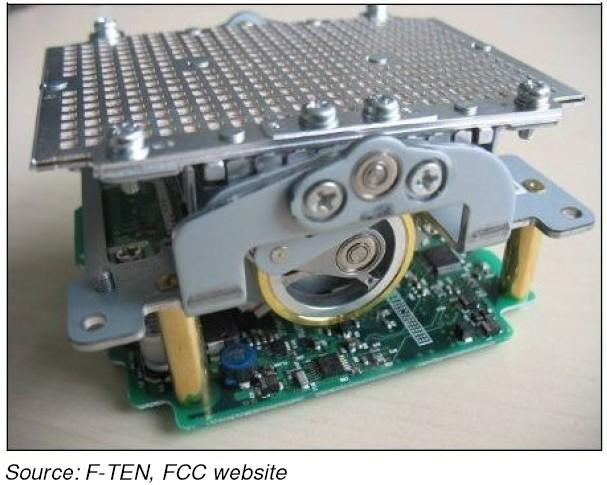
1 Increasing Automotive Safety with 77/79 GHz Radar Solutions for ADAS Applications FTF-AUT-F0086 Patrick Morgan Director, Safety Systems Business Unit Ralf Reuter Manager, Radar Applications and Systems Mark Wilson Product Line Manager, Automotive Radar APR.2014 TM External Use
2 Agenda Market Overview The Fundamentals of Radar Systems Freescale Automotive 77/79 GHz Radar Roadmap Bare Die Radar Chipset MR2001 Scalable Packaged Radar Chipset MR3000 Single Package Radar Transceiver Summary and Conclusions External Use 1
3 Market Overview External Use 2


")
 Chips are highly differentiated")

 Confidential and")
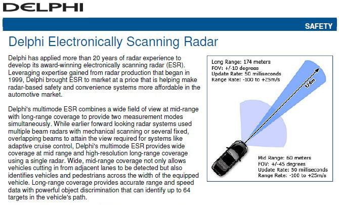
4 Why is Radar Exciting? Market is taking off Electronic scanning Automatic alignment in both azimuth and elevation 3 degree target separation 0.1 degree accuracy 250m range Assistance, safety Autonomous driving trend Units are small, BOM ~$ TAM ~$100M in 2016, CAGR 40% Low power < 5 W Antenna PCB RF+BB (Top) Integration with camera vision systems RF+BB (Bottom) Chips are highly differentiated Valuable Difficult to replicate Currently few qualified suppliers Freescale investing in total solution Radar transceiver (Analog) Radar processor (Auto MCU) Confidential and Proprietary Information under NDA External Use 3
5 Fundamentals of Radar Systems External Use 4
6 The basic radar system (1 Transmit & 1 Receive channel) RADAR (Radio Angle Detection And Ranging) G t Microprocessor - Control - Signal Processing - Object Detection - Object Classification Signal Generation Transmitter Chain LO Receiver Chain Down Conversion P t P r A r R σ Radar Equation: P r 4 PG A σ F R ( 4π ) t t r = 4 2 Constant Symbols P r = Received power P t = Transmitted power G t = Gain of the transmitting antenna σ = Scattering cross section of object A r = Area of the receiving antenna R = Range to the object External Use 5

7 Radar Equation Calculation GTx = 23 dbi GRx = 23 dbi PTx = 10 dbm F=76.5 GHz RCS = 10 Car RCS = -20 Pedestrian External Use 6
8 What is required for the transmit and receive chain? Signal Generation Transmitter Chain VCO PLL PA State - Machine SPI Tx Tx Performance Metrics - Output power - Phase noise - FMCW linearity - Temp performance Timing LO SPI Receiver Chain Down Conversion Rx LNA Mixer BB VGA IF Rx Performance Metrics - Noise figure - Conversion gain - Input linearity - Temp performance State - Machine SPI External Use 7 SPI
9 The basic radar system (1 Transmit & 1 Receive channel) G t Microprocessor - Control - Signal Processing - Object Detection - Object Classification Signal Generation Transmitter Chain LO Receiver Chain Down Conversion P t P r A r R σ Radar Equation: P r 4 PG A σ F R ( 4π ) t t r = 4 2 Constant Symbols P r = Received power P t = Transmitted power G t = Gain of the transmitting antenna σ = Scattering cross section of object A r = Area of the receiving antenna R = Range to the object External Use 8

10 Electronically Scanned Automotive Radar Older Style Mechanically Scanned Radar Source: Continental, Gruson, 2012 Workshop on Antenna External Use 9
11 The Electronic Scanning Radar ESR (n Transmit & m Receive channel) Microprocessor - Control - Signal Processing - Object Detection - Object Classification Signal Generation Transmitter Chain Signal Generation Transmitter Chain LO Receiver Chain Down Conversion Receiver Chain Down Conversion Receiver Chain Down Conversion Different Tx channels can be used to drive different antennas (near and long range scans for instance) Multiple Tx channels can be used simultaneously to provide beam steering capability Multiple Rx channels can be used to obtain angular information about the objects due to phase change of the arriving signal at different receive antenna External Use 10

12 Electronic Beam Forming: Rx External Use 11
13 Transmit Signal Modulation Types Pulse Modulation f t f t Time of Flight vs Object Distance 1000 meters 100 meters 10 meters 1 meter 6.6υs 667ns 67ns 6.7ns Very short pulse generation is difficult in general Difficult to contain the frequency spectrum to regulations Object velocity obtained from Doppler shift At short distances Tx and Rx signal overlap FMCW Modulation (Slow Modulation) f BW T chirp = 5mS Pulse Chirp FMCW (Fast Modulation) f BW T chirp = 30uS t t Beat Frequency f b = 2RBW c t 0 IF Frequencies IF chirp [ f f ] f =, beat doppler Doppler Frequency f doppler = 0.5c = BW 2vr f c Range Resolution R 0 0 tx
14 Example calculation of the radar equations Radar Equations Slow Fast Range (m) Vrel (km/h) Ftx (GHz) BW (MHz) Tchirp (us) Fbeat (khz) Fdoppler (khz) R (m) External Use 13
15 Beat and doppler frequency for fast and slow modulation Fast Modulation IF Band Slow Modulation IF Band V r = 200 km/h V r = 50 km/h V r = 10 km/h External Use 14
16 Tradeoffs Between Slow And Fast Modulation Systems Near Range Scan Long Range Scan Velocity - 0km/h Slow Fast Slow Fast Slow Fast Slow Fast Slow Fast Slow Fast Range (m) Vrel (km/h) Ftx (GHz) BW (MHz) Tchirp (us) Fbeat (khz) Fdoppler (khz) R (m) Near Range Scan Long Range Scan Velocity - 50km/h Slow Fast Slow Fast Slow Fast Slow Fast Slow Fast Slow Fast Range (m) Vrel (km/h) Ftx (GHz) BW (MHz) Tchirp (us) Fbeat (khz) Fdoppler (khz) R (m) Near Range Scan Long Range Scan Velocity - 200km/h Slow Fast Slow Fast Slow Fast Slow Fast Slow Fast Slow Fast Range (m) Vrel (km/h) Ftx (GHz) BW (MHz) Tchirp (us) Fbeat (khz) Fdoppler (khz) R (m) External Use 15

17 Signal Analysis Range Range FFTs real to complex transform, provide SNR gain External Use 16

 External")
18 Signal Analysis Doppler Doppler FFTs Complex to complex Provide SNR gain Determine the relative speed (Doppler gates) External Use 17
19 Why Fast Modulation? Application and System Requirements Fast Modulation Benefits Fast Modulation Tradeoffs SRR, MRR, & LRR radar Multiple target tracking, SNR Target separation, PN Fully supports all modes of operation in one sensor Direct separation of speed and distance since they are not in the same IF band IF frequency band (500 K to 10 MHz) in lower region of PN Larger data cube requires high performance process engine and memory for 3D-FFT Larger data cube requires high performance process engine 3D-FFT Complex design for fast chirp VCOPLL and Tx switching IF bandwidth Power consumption High in MHz range, but out of the 1/f noise range Fast chirps allow reduced operational duty cycle Requires higher performance A/D None External Use 18
20 MR1500 Chipset External Use 19 Content


21 MR1500 Bare Die 77 GHz Radar Transceiver Chipset 4chTxPLL Part number MR1500 Samples: Available PPAP: Q chRx FRDxX1050x Chipset Differentiating Points Highly integrated 77 GHz automotive radar chipset supports up to 4 Tx and 16 Rx channel configurations for 2D, 3D, DBF, and SAR automotive radar applications Supports slow and fast modulation to 10 MHz / 100 ns Fully integrated PLL and chirp generator programmed via SPI along with Tx power level, channel activation, and state machine control Designed for integration with a multitude of microprocessors including Freescale s MPC567xK MCU SPI Programmable Chirp External Use 20
22 MR2001 Chipset External Use 21 Content


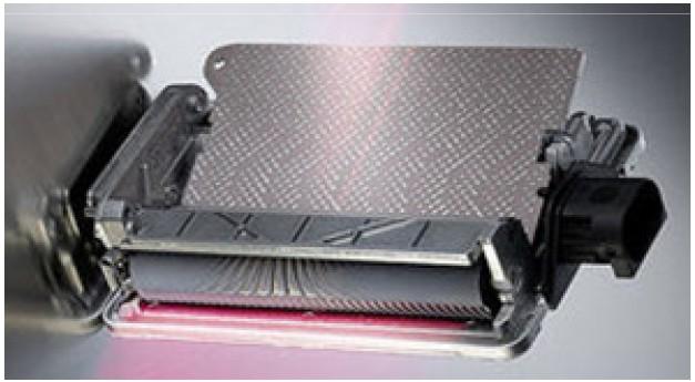
23 MR2001 Packaged 77 GHz Radar Chipset The MR2001 chipset is a scalable radar solution for high end and low end ADAS applications, industrial safety, security, and robotics Differentiating Points Scalable to 4 TX channels and 12 RX channels Activate simultaneous Tx channels for electronic beam steering Supports fast modulation at 100 MHz / 100 ns Integrated baseband filter and VGA saves system bill-ofmaterials cost Local oscillator at 38 GHz to lower the distribution loss and reduce system interference Key Characteristics Low power consumption 2.5 W typical for the complete transceiver chipset Differential Tx outputs delivering minimum 10 dbm with 5-bit digital power control Advanced packaging technology with BGA format Integrated bi-phase modulator for advanced correlation coding Built-in receive chain test mode when using Qorivva MPC577xK microprocessor Best phase noise performance < -85 dbc/hz at 100 khz offset, and -95 dbc/hz at 1 MHz offset Temperature detector on each MR2001 chip Typical Application Diagram Samples: Now PPAP: Q Preliminary Subject to Change Without Notice External Use 22


24 MR GHz Chipset and Qorivva MPC577xK MCU RF_Rx BB Filter, Amplifier A A D D C C MPC567xK Previous Generation RF_Tx D A C FPGA Signal Processing Timing Controller Chirp Generation SRAM Next Generation MR GHz Chipset Replaces: Bare Die RF solutions with a RF Chipset based on RCP package technology Discrete Filter Components and Amplifiers MRD2001 Rx MRD2001 Tx MRD2001 VCO MPC577xK Qorivva MPC577xK MCU Replaces: 8 ADC 1 DAC 1 FPGA External SRAM General purpose MCU Enables: Enables: Significant PCB area saving Significantly lower assembly cost Reduced assembly cost Lower PCB cost External Use 23


25 MR2001 Packaged 38 GHz 4-Channel VCO 38 to 38.5 GHz Output Supply Voltage 3.3 V, 4.5 V +/- 5% Supply Current typ. 180 ma, 50 ma Power Dissipation 0.8 W Tuning Voltage 0.2 to 4.2 V KVCO 2.5 GHz/V * Pushing typ. 250 MHz/V * Static Pulling < 10 MHz * Phase Noise typ. -95 dbc/hz@1 MHz * LO Power min. 3 dbm Power Control (4 steps) * values are transferred to 77 GHz External Use 24
26 MR2001 VCO Phase Noise vs. Offset Frequency Related to FC=2* oscillation frequency Phase noise / [dbc/hz] Index Phase noise/[dbc/hz] for VCC+/-5%, T=025 C Cell=RCP FC=75GHz -30 FC=76GHz -40 FC=76.5GHz FC=77GHz -50 FC=78GHz T=25 C Offset Frequency / [KHz] Targeted Parameters Parameter Name Max Values VCO28 PN_10kHz -40 VCO29 PN_100kHz -70 VCO30 PN_1MHz -92 VCO31 PN_10MHz -112 External Use 25 Measured Max Values PN@ offset-freq PN@10KHz -45 PN@100KHz -71 PN@1MHz -94 [dbc/hz] PN@10MHz -117 Phase noise / [dbc/hz] Phase noise / [dbc/hz] Phase noise/[dbc/hz] for VCC+/-5%, T=125 C Cell=RCP FC=75GHz -30 FC=76GHz -40 FC=76.5GHz FC=77GHz -50 FC=78GHz Offset Frequency / [KHz] T=125 C Phase noise/[dbc/hz] for VCC+/-5%, T=-40 C Cell=RCP363 T=-40 C FC=75GHz FC=76GHz FC=76.5GHz FC=77GHz FC=78GHz Offset Frequency / [KHz]
 Tx Power typ.")
27 MR2001 Packaged 77 GHz 2-Channel Tx 76 to 81 GHz Tx Output 38 to 40.5 GHz LO Input Supply Voltage 3.3 V +/- 5% Supply Current typ. 280 ma Power Dissipation 0.9 W Power Control (6-bit) Tx Power typ. 2 x 10 dbm Bi-Phase Modulation SPI (slow) and dedicated control (fast) External Use 26
28 MR2001 Tx Output Power vs Temperature External Use 27
 On Chip RF and baseband test concept Linearity > -5 dbm Conversion Gain 23-60 db @ 4 MHz SSB Noise Figure typ.")
29 MR2001 Packaged 77GHz 3-Channel Rx 76 to 77 GHz RX input 38 to 38.5 GHz LO input Supply Voltage 3.3 V +/- 5% Supply Current typ. 240 ma Power Dissipation typ. 0.8 W Baseband suitable for Qorivva MPC577xK MCU (5 MHz) On Chip RF and baseband test concept Linearity > -5 dbm Conversion Gain MHz SSB Noise Figure typ. 14 db Saturation Detectors Tri-State IF Outputs External Use 28
 Suppression of Tx1 to Tx2 PTX2 (dbm) PTX1 (dbm) Suppression of Tx2 to Tx1 25 C VCCL 13.3780307-31.1264364 44.5044671 13.19151078-29.7696062 42.96111698 VCCN 13.62436295-29.1294747 42.")
30 Channel to Channel Isolation Performance RCP Packaged on RF Test Board 2chTx, channel to channel isolation RCP part#83 Temp VCC TX1 enabled, TX2 disabled TX2 enabled, TX1 disabled PTX1 (dbm) PTX2 (dbm) Suppression of Tx1 to Tx2 PTX2 (dbm) PTX1 (dbm) Suppression of Tx2 to Tx1 25 C VCCL VCCN VCCH C VCCL VCCN VCCH C VCCL VCCN VCCH RCP part#51 min. suppression min. suppression chRx, channel to channel 1MHz External Use 29
31 MR3000 Radar Transceiver External Use 30 Content
32 System (MIPI-CSI2): 4 Tx + 4 Rx External Use 31
33 System (MIPI-CSI2): 4 Tx + 8 Rx External Use 32

34 Please visit the radar demo A3 External Use 33
35 Summary and Conclusions External Use 34 Content
36 Summary and Conclusions 76/79 GHz automotive radar will play a critical role in Vision Zero and the fully autonomous driving car The increasing number of radar modules in the car puts extensive pressure on the following features Size, weight, and power do matter integration counts Tx and Rx channel count differentiate low and high end systems Packaged products are a must for ease of manufacturing at 77 GHz Fast modulation is the trend today for automotive radar The unambiguous direct separation of object range, velocity, and angle is critical in ADAS systems for object rich environments Freescale has an extensive portfolio of radar solutions that can address these requirements External Use 35
37 Freescale Semiconductor, Inc. External Use
Radar Devices, Challenges and Packaging Technology Solutions
 Radar Devices, Challenges and Packaging Technology Solutions FTF-SDS-F0023 Darrel Frear Packaging Technology Development APR.2014 TM External Use Session Introduction This presentation is an overview of
76-81GHz MMIC transceiver (4 RX / 3 TX) for automotive radar applications. Table 1. Device summary. Order code Package Packing
 for automotive radar applications. Table 1. Device summary. Order code Package Packing") STRADA770 76-81GHz MMIC transceiver (4 RX / 3 TX) for automotive radar applications Data brief ESD protected Scalable architecture (master/slave configuration) BIST structures Bicmos9MW, 0.13-µm SiGe:C
STRADA770 76-81GHz MMIC transceiver (4 RX / 3 TX) for automotive radar applications Data brief ESD protected Scalable architecture (master/slave configuration) BIST structures Bicmos9MW, 0.13-µm SiGe:C
Scalable Front-End Digital Signal Processing for a Phased Array Radar Demonstrator. International Radar Symposium 2012 Warsaw, 24 May 2012
 Scalable Front-End Digital Signal Processing for a Phased Array Radar Demonstrator F. Winterstein, G. Sessler, M. Montagna, M. Mendijur, G. Dauron, PM. Besso International Radar Symposium 2012 Warsaw,
RSE02401/00 24 GHz Radar Sensor
 General description The RSE02401/00 is a fully integrated K-band FMCW radar sensor. It utilizes packaged low-cost components, enabling low unit prices and high volumes, using SMT assembly technology, with
K-MC4 MONOPULSE RADAR TRANSCEIVER. Features. Applications. Description. Blockdiagram. Datasheet
 Features 24 GHz short range monopulse transceiver Dual receiver +/- 15 angle coverage Beam aperture 30/ 12 @ -3 180MHz sweep FM input High sensitivity, integrated RF/IF amplifier Buffered I/Q IF outputs
Radar System Design Considerations -- System Modeling Findings (MOS-AK Conference Hangzhou 2017)
") Radar System Design Considerations -- System Modeling Findings (MOS-AK Conference Hangzhou 2017) Silicon Radar GmbH Im Technologiepark 1 15236 Frankfurt (Oder) Germany Outline 1 Introduction to Short Distance
Radar System Design Considerations -- System Modeling Findings (MOS-AK Conference Hangzhou 2017) Silicon Radar GmbH Im Technologiepark 1 15236 Frankfurt (Oder) Germany Outline 1 Introduction to Short Distance
K-MC1 RADAR TRANSCEIVER. Features. Applications. Description. Blockdiagram. Datasheet
 Features 24 GHz short range transceiver 180 MHz sweep FM input High sensitivity, with integrated RF/IF amplifier Dual 30 patch antenna Buffered I/Q IF outputs Additional DC IF outputs Beam aperture 25
K-LC2 RADAR TRANSCEIVER
 Features 24 GHz K-band miniature I/Q transceiver 140MHz sweep FM input 2 x 4 patch antenna 2 balanced mixer with 50MHz bandwidth Excellent noise cancelling ability though I/Q technology Beam aperture 80
This article reports on
 Millimeter-Wave FMCW Radar Transceiver/Antenna for Automotive Applications A summary of the design and performance of a 77 GHz radar unit David D. Li, Sam C. Luo and Robert M. Knox Epsilon Lambda Electronics
K-MC2 RADAR TRANSCEIVER Replaced by K-MC3 Datasheet. Features. Applications. Description. Blockdiagram
 Features 24 GHz short range transceiver 90MHz sweep FM input High sensitivity, integrated RF/IF amplifier Dual 62 patch narrow beam antenna Buffered, gain adjustable I/Q IF outputs Additional DC IF outputs
Session 3. CMOS RF IC Design Principles
 Session 3 CMOS RF IC Design Principles Session Delivered by: D. Varun 1 Session Topics Standards RF wireless communications Multi standard RF transceivers RF front end architectures Frequency down conversion
Radar Market Outlook. Mats Carlsson CTO. Sivers IMA Partner Event - June
 Radar Market Outlook Mats Carlsson CTO Sivers IMA Partner Event - June 2017 1 Why radar? Competing non-contact technologies Vision / cameras Time of flight Stereoscopic Lasers Ultrasound Radar offers robust
S-Band 2.4GHz FMCW Radar
 S-Band 2.4GHz FMCW Radar Iulian Rosu, YO3DAC / VA3IUL, Filip Rosu, YO3JMK, http://qsl.net/va3iul A Radar detects the presence of objects and locates their position in space by transmitting electromagnetic
Effects to develop a high-performance millimeter-wave radar with RF CMOS technology
 Effects to develop a high-performance millimeter-wave radar with RF CMOS technology Yasuyoshi OKITA Kiyokazu SUGAI Kazuaki HAMADA Yoji OHASHI Tetsuo SEKI High Resolution Angle-widening Abstract We are
mm-wave Transceiver Challenges for the 5G and 60GHz Standards Prof. Emanuel Cohen Technion
 mm-wave Transceiver Challenges for the 5G and 60GHz Standards Prof. Emanuel Cohen Technion November 11, 11, 2015 2015 1 mm-wave advantage Why is mm-wave interesting now? Available Spectrum 7 GHz of virtually
SiGe PLL design at 28 GHz
 SiGe PLL design at 28 GHz 2015-09-23 Tobias Tired Electrical and Information Technology Lund University May 14, 2012 Waqas Ahmad (Lund University) Presentation outline E-band wireless backhaul Beam forming
Simulating and Testing of Signal Processing Methods for Frequency Stepped Chirp Radar
 Test & Measurement Simulating and Testing of Signal Processing Methods for Frequency Stepped Chirp Radar Modern radar systems serve a broad range of commercial, civil, scientific and military applications.
RF and Microwave Test and Design Roadshow 5 Locations across Australia and New Zealand
 RF and Microwave Test and Design Roadshow 5 Locations across Australia and New Zealand ni.com Design and test of RADAR systems Agenda Radar Overview Tools Overview VSS LabVIEW PXI Design and Simulation
Millimeter Wave Radar using Stepped Multiple Frequency. Complementary Phase Code Modulation
 Millimeter Wave Radar using Stepped Multiple Frequency Complementary Phase Code Modulation Masato Watanabe Manabu Akita Takayuki Inaba Graduate School of Electro-Communications, The University of Electro-Communications
A 1.7-to-2.2GHz Full-Duplex Transceiver System with >50dB Self-Interference Cancellation over 42MHz Bandwidth
 A 1.7-to-2.2GHz Full-Duplex Transceiver System with >50dB Self-Interference Cancellation Tong Zhang, Ali Najafi, Chenxin Su, Jacques C. Rudell University of Washington, Seattle Feb. 8, 2017 International
DS H01 DIGITAL SYNTHESIZER MODULE SYSTEM SOLUTIONS. Features Applications 174 x 131 x 54 mm. Technical Description
 DS H01 The DS H01 is a high performance dual digital synthesizer with wide output bandwidth specially designed for Defense applications where generation of wideband ultra-low noise signals along with very
FEATURES DESCRIPTION BENEFITS APPLICATIONS. Preliminary PT4501 Sub-1 GHz Wideband FSK Transceiver
 Preliminary PT4501 Sub-1 GHz Wideband FSK Transceiver DESCRIPTION The PT4501 is a highly integrated wideband FSK multi-channel half-duplex transceiver operating in sub-1 GHz license-free ISM bands. The
Frequently asked questions for 24 GHz industrial radar
 Frequently asked questions for 24 GHz industrial radar What is radar? Radar is an object-detection system that uses radio waves to determine the range, angle, or velocity of objects. A radar system consists
26.8: A 1.9GHz Single-Chip CMOS PHS Cellphone
 26.8: A 1.9GHz Single-Chip CMOS PHS Cellphone William W. Si, Srenik Mehta, Hirad Samavati, Manolis Terrovitis, Michael Mack, KeithOnodera, SteveJen, Susan Luschas, Justin Hwang, SuniMendis, DavidSu, BruceWooley
Digital Receiver Experiment or Reality. Harry Schultz AOC Aardvark Roost Conference Pretoria 13 November 2008
 Digital Receiver Experiment or Reality Harry Schultz AOC Aardvark Roost Conference Pretoria 13 November 2008 Contents Definition of a Digital Receiver. Advantages of using digital receiver techniques.
User Manual WHM520V. 1. Introduction. 2. Feature
 User Manual 1 Introduction The module is wireless audio module based on AV5100 The AV5100 is 5GHz wireless audio SoC (System-on-chip), optimized for building point to multi-point digital wireless audio
Cascaded Radar And Body&Chassis Automotive Applications. Dan Wang, System Manager, Radar & Analytics, EP
 Cascaded Radar And Body&Chassis Automotive Applications Dan Wang, System Manager, Radar & Analytics, EP 1 Dan Wang System Manager, Radar & Analytics Career PhD, Electrical Engineering, University of Texas
TRX_120_01 RFE (Radar Front End) 120 GHz Highly Integrated IQ Transceiver with Antennas in Package (Silicon Germanium Technology)
 120 GHz Highly Integrated IQ Transceiver with Antennas in Package (Silicon Germanium Technology)") Silicon Radar GmbH Im Technologiepark 1 15236 Frankfurt (Oder) Germany fon +49.335.557 17 60 fax +49.335.557 10 50 http://www.siliconradar.com TRX_120_01 RFE (Radar Front End) 120 GHz Highly Integrated
Silicon Radar GmbH Im Technologiepark 1 15236 Frankfurt (Oder) Germany fon +49.335.557 17 60 fax +49.335.557 10 50 http://www.siliconradar.com TRX_120_01 RFE (Radar Front End) 120 GHz Highly Integrated
The Future Autonomous Driving Techniques and Test Challenges. Sr. Project Manager / Keysight Technologies
 The Future Autonomous Driving Techniques and Test Challenges Sr. Project Manager / Keysight Technologies Brian Su 2018.06.11 Taipei 2 3 Autonomous Driving & e-mobility Data Source: WHO, US EPA 4 Traffic
Digital Baseband Architecture in AR1243/AR1642 Automotive Radar Devices
 Application Report Lit. Number June 015 Digital Baseband Architecture in AR143/AR164 Automotive Radar Devices Sriram Murali, Karthik Ramasubramanian Wireless Connectivity Solutions ABSTRACT This application
60 GHz Receiver (Rx) Waveguide Module
 Waveguide Module") The PEM is a highly integrated millimeter wave receiver that covers the GHz global unlicensed spectrum allocations packaged in a standard waveguide module. Receiver architecture is a double conversion,
The PEM is a highly integrated millimeter wave receiver that covers the GHz global unlicensed spectrum allocations packaged in a standard waveguide module. Receiver architecture is a double conversion,
A 1.9GHz Single-Chip CMOS PHS Cellphone
 A 1.9GHz Single-Chip CMOS PHS Cellphone IEEE JSSC, Vol. 41, No.12, December 2006 William Si, Srenik Mehta, Hirad Samavati, Manolis Terrovitis, Michael Mack, Keith Onodera, Steve Jen, Susan Luschas, Justin
60 GHz RX. Waveguide Receiver Module. Features. Applications. Data Sheet V60RXWG3. VubIQ, Inc
 GHz RX VRXWG Features Complete millimeter wave receiver WR-, UG-8/U flange Operates in the to GHz unlicensed band db noise figure Up to.8 GHz modulation bandwidth I/Q analog baseband interface Integrated
Package and Pin Assignment SSOP-6 (0.64mm pitch) OSCIN OSCOUT TXEN 3 VSS 4 TXOUT 5 VSS 6 7 MODIN 8 HiMARK SW DO RES RESB VREFP VSS Symbol
 OSCIN OSCOUT TXEN 3 VSS 4 TXOUT 5 VSS 6 7 MODIN 8 HiMARK SW DO RES RESB VREFP VSS Symbol") Low Power ASK Transmitter IC HiMARK Technology, Inc. reserves the right to change the product described in this datasheet. All information contained in this datasheet is subject to change without prior
Low Power ASK Transmitter IC HiMARK Technology, Inc. reserves the right to change the product described in this datasheet. All information contained in this datasheet is subject to change without prior
Project: IEEE P Working Group for Wireless Personal Area Networks (WPANS)
") Project: IEEE P802.15 Working Group for Wireless Personal Area Networks (WPANS) Title: [General Atomics Call For Proposals Presentation] Date Submitted: [4 ] Source: Naiel Askar, Susan Lin, General Atomics-
Project: IEEE P802.15 Working Group for Wireless Personal Area Networks (WPANS) Title: [General Atomics Call For Proposals Presentation] Date Submitted: [4 ] Source: Naiel Askar, Susan Lin, General Atomics-
RF/IF Terminology and Specs
 RF/IF Terminology and Specs Contributors: Brad Brannon John Greichen Leo McHugh Eamon Nash Eberhard Brunner 1 Terminology LNA - Low-Noise Amplifier. A specialized amplifier to boost the very small received
ISSCC 2003 / SESSION 20 / WIRELESS LOCAL AREA NETWORKING / PAPER 20.2
 ISSCC 2003 / SESSION 20 / WIRELESS LOCAL AREA NETWORKING / PAPER 20.2 20.2 A Digitally Calibrated 5.15-5.825GHz Transceiver for 802.11a Wireless LANs in 0.18µm CMOS I. Bouras 1, S. Bouras 1, T. Georgantas
ISSCC 2003 / SESSION 20 / WIRELESS LOCAL AREA NETWORKING / PAPER 20.5
 ISSCC 2003 / SESSION 20 / WIRELESS LOCAL AREA NETWORKING / PAPER 20.5 20.5 A 2.4GHz CMOS Transceiver and Baseband Processor Chipset for 802.11b Wireless LAN Application George Chien, Weishi Feng, Yungping
77 GHz VCO for Car Radar Systems T625_VCO2_W Preliminary Data Sheet
 77 GHz VCO for Car Radar Systems Preliminary Data Sheet Operating Frequency: 76-77 GHz Tuning Range > 1 GHz Output matched to 50 Ω Application in Car Radar Systems ESD: Electrostatic discharge sensitive
Modern radio techniques
 Modern radio techniques for probing the ionosphere Receiver, radar, advanced ionospheric sounder, and related techniques Cesidio Bianchi INGV - Roma Italy Ionospheric properties related to radio waves
TRA_120_002 Radar Front End 120-GHz Highly Integrated IQ Transceiver with Antennas on Chip in Silicon Germanium Technology
 Silicon Radar GmbH Im Technologiepark 1 15236 Frankfurt (Oder) Germany fon +49.335.557 17 60 fax +49.335.557 10 50 http://www.siliconradar.com TRA_120_002 Radar Front End 120-GHz Highly Integrated IQ Transceiver
ELEC RADAR FRONT-END SUMMARY
 ELEC Radar Front-End is designed for FMCW (including CW) radar application. The output frequency of each RX provides range, speed, and amplitude information to DSP. It will detect target azimuth angle
Industrial radar sensing. April 2018
 Industrial radar sensing April 2018 The world is getting smarter An ever increasing number of sensors assist, enable and keep us safe everyday Radar is a smart sensor, with advanced sensing capabilities
Continuous Wave Radar
 Continuous Wave Radar CW radar sets transmit a high-frequency signal continuously. The echo signal is received and processed permanently. One has to resolve two problems with this principle: Figure 1:
Mm-Wave Silicon Sensors. and Active Tags
 Mm-Wave Silicon Sensors and Active Tags Sorin Voinigescu November 21, 2014 1 Outline Introduction Range (distance) sensors Passive imaging sensors Active 80-GHz tag Technology options Conclusions 2 Why
Fully integrated UHF RFID mobile reader with power amplifiers using System-in-Package (SiP)
") Fully integrated UHF RFID mobile reader with power amplifiers using System-in-Package (SiP) Hyemin Yang 1, Jongmoon Kim 2, Franklin Bien 3, and Jongsoo Lee 1a) 1 School of Information and Communications,
Fully integrated UHF RFID mobile reader with power amplifiers using System-in-Package (SiP) Hyemin Yang 1, Jongmoon Kim 2, Franklin Bien 3, and Jongsoo Lee 1a) 1 School of Information and Communications,
An All CMOS, 2.4 GHz, Fully Adaptive, Scalable, Frequency Hopped Transceiver
 An All CMOS, 2.4 GHz, Fully Adaptive, Scalable, Frequency Hopped Transceiver Farbod Behbahani John Leete Alexandre Kral Shahrzad Tadjpour Karapet Khanoyan Paul J. Chang Hooman Darabi Maryam Rofougaran
Space Frequency Coordination Group
 Space Frequency Coordination Group Report SFCG 38-1 POTENTIAL RFI TO EESS (ACTIVE) CLOUD PROFILE RADARS IN 94.0-94.1 GHZ FREQUENCY BAND FROM OTHER SERVICES Abstract This new SFCG report analyzes potential
System-on-Chip Two-Way Radio
 System-on-Chip Two-Way Radio FTF-CON-F0508 Steve Johnson / Keith Tilley Product Management 31 August 2011 Freescale, the Freescale logo, AltiVec, C-5, CodeTEST, CodeWarrior, ColdFire, C-Ware, t he Energy
Technology Trend of Ultra-High Data Rate Wireless CMOS Transceivers
 2017.07.03 Technology Trend of Ultra-High Data Rate Wireless CMOS Transceivers Akira Matsuzawa and Kenichi Okada Tokyo Institute of Technology Contents 1 Demand for high speed data transfer Developed high
60 GHz TX. Waveguide Transmitter Module. Data Sheet Features V60TXWG3. Applications. VubIQ, Inc
 Features Complete millimeter wave transmitter WR-, UG-8/U flange Operates in the to GHz unlicensed band dbm typical output power Up to.8 GHz modulation bandwidth I/Q analog baseband interface On chip synthesizer
GET10B Radar Measurement Basics- Spectrum Analysis of Pulsed Signals. Copyright 2001 Agilent Technologies, Inc.
 GET10B Radar Measurement Basics- Spectrum Analysis of Pulsed Signals Copyright 2001 Agilent Technologies, Inc. Agenda: Power Measurements Module #1: Introduction Module #2: Power Measurements Module #3:
Windfreak Technologies SynthHD v1.4 Preliminary Data Sheet v0.2b
 Windfreak Technologies SynthHD v1.4 Preliminary Data Sheet v0.2b $1299.00US 54 MHz 13.6 GHz Dual Channel RF Signal Generator Features Open source Labveiw GUI software control via USB Run hardware functions
Information furnished by IMSEMI is believed to be accurate and reliable. However, no responsibility is assumed by IMSEMI for its use, nor for any
 SG24T1 24 GHz transmitter MMIC Data Sheet Revision 0.0, 2015-11-18 Information furnished by IMSEMI is believed to be accurate and reliable. However, no responsibility is assumed by IMSEMI for its use,
Keysight Technologies
 Keysight Technologies Generating Signals Basic CW signal Block diagram Applications Analog Modulation Types of analog modulation Block diagram Applications Digital Modulation Overview of IQ modulation
Keywords: GPS, receiver, GPS receiver, MAX2769, 2769, 1575MHz, Integrated GPS Receiver, Global Positioning System
 Maxim > Design Support > Technical Documents > User Guides > APP 3910 Keywords: GPS, receiver, GPS receiver, MAX2769, 2769, 1575MHz, Integrated GPS Receiver, Global Positioning System USER GUIDE 3910 User's
Digitally-Controlled RF Self- Interference Canceller for Full-Duplex Radios
 Digitally-Controlled RF Self- nterference Canceller for Full-Duplex Radios Joose Tamminen 1, Matias Turunen 1, Dani Korpi 1, Timo Huusari 2, Yang-Seok Choi 2, Shilpa Talwar 2, and Mikko Valkama 1 1 Dept.
NANOSCALE IMPULSE RADAR
 NANOSCALE IMPULSE RADAR NVA6X00 Impulse Radar Transceiver and Development Kit 2012.4.20 laon@laonuri.com 1 NVA6000 The Novelda NVA6000 is a single-die CMOS chip that delivers high performance, low power,
Full Duplex Radios. Sachin Katti Kumu Networks & Stanford University 4/17/2014 1
 Full Duplex Radios Sachin Katti Kumu Networks & Stanford University 4/17/2014 1 It is generally not possible for radios to receive and transmit on the same frequency band because of the interference that
Receiver Architecture
 Receiver Architecture Receiver basics Channel selection why not at RF? BPF first or LNA first? Direct digitization of RF signal Receiver architectures Sub-sampling receiver noise problem Heterodyne receiver
White paper on CAR28T millimeter wave radar
 White paper on CAR28T millimeter wave radar Hunan Nanoradar Science and Technology Co., Ltd. Version history Date Version Version description 2017-07-13 1.0 the 1st version of white paper on CAR28T Contents
Design Considerations for 5G mm-wave Receivers. Stefan Andersson, Lars Sundström, and Sven Mattisson
 Design Considerations for 5G mm-wave Receivers Stefan Andersson, Lars Sundström, and Sven Mattisson Outline Introduction to 5G @ mm-waves mm-wave on-chip frequency generation mm-wave analog front-end design
RFM110 RFM110. Low-Cost MHz OOK Transmitter RFM110 RFM110. Features. Descriptions. Applications. Embedded EEPROM
 Features Embedded EEPROM RFM110 Low-Cost 240 480 MHz OOK Transmitter Very Easy Development with RFPDK All Features Programmable Frequency Range: 240 to 480 MHz OOK Modulation Symbol Rate: 0.5 to 30 kbps
60 GHz Transmitter (Tx) Waveguide Module
 Waveguide Module") The is a highly integrated millimeter wave transmitter that covers the 60 GHz global unlicensed spectrum allocations packaged in a standard waveguide module. Transmitter architecture is a double conversion,
The is a highly integrated millimeter wave transmitter that covers the 60 GHz global unlicensed spectrum allocations packaged in a standard waveguide module. Transmitter architecture is a double conversion,
A Low Phase Noise 24/77 GHz Dual-Band Sub-Sampling PLL for Automotive Radar Applications in 65 nm CMOS Technology
 A Low Phase Noise 24/77 GHz Dual-Band Sub-Sampling PLL for Automotive Radar Applications in 65 nm CMOS Technology Xiang Yi, Chirn Chye Boon, Junyi Sun, Nan Huang and Wei Meng Lim VIRTUS, Nanyang Technological
AL2230S Single Chip Transceiver for 2.4GHz b/g Applications (AIROHA)
") AL2230S Single Chip Transceiver for 2.4GHz 802.11b/g Applications (AIROHA) AL2230S Datasheet MP v1.00-1 - This document is commercially confidential and must NOT be disclosed to third parties without prior
AL2230S Single Chip Transceiver for 2.4GHz 802.11b/g Applications (AIROHA) AL2230S Datasheet MP v1.00-1 - This document is commercially confidential and must NOT be disclosed to third parties without prior
Switched Monopulse Radar for Automotive Applications SLR. Tyco Electronics M/A-COM European Technology & Application Center Schweinfurt, Germany
 Switched Monopulse Radar for Automotive Applications SLR Tyco Electronics M/A-COM European Technology & Application Center Schweinfurt, Germany Typical Applications Blind Spot Detection Improved ACC Functionality
NanoCom TR-600. Datasheet Nano-satellite transceiver
 NanoCom TR-600 Datasheet Nano-satellite transceiver 1 Table of Contents 1 TABLE OF CONTENTS... 2 2 OVERVIEW... 3 2.1 HIGHLIGHTED FEATURES... 3 2.2 BLOCK DIAGRAM... 4 2.3 AD9361 TRANSCEIVER DATASHEET...
Demo board DC365A Quick Start Guide.
 August 02, 2001. Demo board DC365A Quick Start Guide. I. Introduction The DC365A demo board is intended to demonstrate the capabilities of the LT5503 RF transmitter IC. This IC incorporates a 1.2 GHz to
Preliminary features of the SDR-X receiver SDR-X , PowerSDR Winrad Winrad DDS SFDR SFDR AD995 AD99 1
 Preliminary features of the SDR-X receiver The SDR-X receiver, in its full version is capable of continuously tuning the entire HF spectrum, 6m ( 50-52 MHz) band included. SSB, AM etc. demodulation, bandpass
UWB Hardware Issues, Trends, Challenges, and Successes
 UWB Hardware Issues, Trends, Challenges, and Successes Larry Larson larson@ece.ucsd.edu Center for Wireless Communications 1 UWB Motivation Ultra-Wideband Large bandwidth (3.1GHz-1.6GHz) Power spectrum
ECEN620: Network Theory Broadband Circuit Design Fall 2014
 ECEN60: Network Theory Broadband Circuit Design Fall 014 Lecture 13: Frequency Synthesizer Examples Sam Palermo Analog & Mixed-Signal Center Texas A&M University Agenda Frequency Synthesizer Examples Design
SYSTEM ARCHITECTURE OF RADAR NETWORK FOR MONITORING OF HAZARDOUD WEATHER
 SYSTEM ARCHITECTURE OF RADAR NETWORK FOR MONITORING OF HAZARDOUD WEATHER 2008. 11. 21 HOON LEE Gwangju Institute of Science and Technology &. CONTENTS 1. Backgrounds 2. Pulse Compression 3. Radar Network
Radar and Functional Safety technology for advanced driving assistance
 Radar and Functional Safety technology for advanced driving assistance Yves Legrand (Freescale Semiconductor) This presentation will describe advanced development in 77 GHz radar technology, enabling smaller
APPLICATION NOTE II. Detection and ranging of moving and stationary objects by using the FMCW radar principle.
 APPLICATION NOTE II Detection and ranging of moving and stationary objects by using the FMCW radar principle www.innosent.de Editorial InnoSenT GmbH want provide to beginners and first-time users an easy
Low Power Communication Circuits for WSN
 Low Power Communication Circuits for WSN Nate Pletcher, Prof. Jan Rabaey, (B. Otis, Y.H. Chee, S. Gambini, D. Guermandi) Berkeley Wireless Research Center Towards A Micropower Integrated Node power management
Features. = +25 C, Vdc = +12V
 Typical Applications The VCO Module is ideal for: Industrial/Medical Equipment Test & Measurement Equipment Military Radar, EW & ECM Lab Instrumentation Functional Diagram Electrical Specifications, T
TSEK38 Radio Frequency Transceiver Design: Project work B
 TSEK38 Project Work: Task specification A 1(15) TSEK38 Radio Frequency Transceiver Design: Project work B Course home page: Course responsible: http://www.isy.liu.se/en/edu/kurs/tsek38/ Ted Johansson (ted.johansson@liu.se)
76-77 GHz RF receiver front-end for W-band radar applications
 NXP Semiconductors Data Sheet: Advance Information 76-77 GHz RF receiver front-end for W-band radar applications The MR2001 is an expandable three package solution for automotive radar modules. The chipset
Maximizing MIMO Effectiveness by Multiplying WLAN Radios x3
 ATHEROS COMMUNICATIONS, INC. Maximizing MIMO Effectiveness by Multiplying WLAN Radios x3 By Winston Sun, Ph.D. Member of Technical Staff May 2006 Introduction The recent approval of the draft 802.11n specification
ELEN 701 RF & Microwave Systems Engineering. Lecture 2 September 27, 2006 Dr. Michael Thorburn Santa Clara University
 ELEN 701 RF & Microwave Systems Engineering Lecture 2 September 27, 2006 Dr. Michael Thorburn Santa Clara University Lecture 2 Radio Architecture and Design Considerations, Part I Architecture Superheterodyne
Understanding Low Phase Noise Signals. Presented by: Riadh Said Agilent Technologies, Inc.
 Understanding Low Phase Noise Signals Presented by: Riadh Said Agilent Technologies, Inc. Introduction Instabilities in the frequency or phase of a signal are caused by a number of different effects. Each
Radar Echo Generator Application Note
 Radar Echo Generator Application Note Products: R&S FSW R&S SMW200A R&S ZVA R&S RTO Radar test systems are essential in research, development, production and maintenance of radar systems. Most radar tests
24 GHz ISM Band Integrated Transceiver Preliminary Technical Documentation MAIC
 FEATURES Millimeter-wave (mmw) integrated transceiver Direct up and down conversion architecture 24 GHz ISM band 23.5-25.5 GHz frequency of operation 1.5 Volt operation, low-power consumption LO Quadrature
A COMPACT, AGILE, LOW-PHASE-NOISE FREQUENCY SOURCE WITH AM, FM AND PULSE MODULATION CAPABILITIES
 A COMPACT, AGILE, LOW-PHASE-NOISE FREQUENCY SOURCE WITH AM, FM AND PULSE MODULATION CAPABILITIES Alexander Chenakin Phase Matrix, Inc. 109 Bonaventura Drive San Jose, CA 95134, USA achenakin@phasematrix.com
INTRODUCTION TO TRANSCEIVER DESIGN ECE3103 ADVANCED TELECOMMUNICATION SYSTEMS
 INTRODUCTION TO TRANSCEIVER DESIGN ECE3103 ADVANCED TELECOMMUNICATION SYSTEMS FUNCTIONS OF A TRANSMITTER The basic functions of a transmitter are: a) up-conversion: move signal to desired RF carrier frequency.
TRX_120_ GHz Highly Integrated IQ Transceiver with Antennas in Package in Silicon Germanium Technology
 Silicon Radar GmbH Im Technologiepark 1 15236 Frankfurt (Oder) Germany fon +49.335.557 17 60 fax +49.335.557 10 50 https://www.siliconradar.com TRX_120_001 120-GHz Highly Integrated IQ Transceiver with
Developing a Generic Software-Defined Radar Transmitter using GNU Radio
 Developing a Generic Software-Defined Radar Transmitter using GNU Radio A thesis submitted in partial fulfilment of the requirements for the degree of Master of Sciences (Defence Signal Information Processing)
RDA1845 SINGLE CHIP TRANSCEIVER FOR WALKIE TALKIE. 1. General Description. Rev.1.0 Feb.2008
 RDA1845 SINGLE CHIP TRANSCEIVER FOR WALKIE TALKIE Rev.1.0 Feb.2008 1. General Description The RDA1845 is a single-chip transceiver for Walkie Talkie with fully integrated synthesizer, IF selectivity and
Radio Research Directions. Behzad Razavi Communication Circuits Laboratory Electrical Engineering Department University of California, Los Angeles
 Radio Research Directions Behzad Razavi Communication Circuits Laboratory Electrical Engineering Department University of California, Los Angeles Outline Introduction Millimeter-Wave Transceivers - Applications
Today s mobile devices
 PAGE 1 NOVEMBER 2013 Highly Integrated, High Performance Microwave Radio IC Chipsets cover 6-42 GHz Bands Complete Upconversion & Downconversion Chipsets for Microwave Point-to-Point Outdoor Units (ODUs)
GPS7500 Noise & Interference Generator
 All-in-one for valuable GPS interference testing GPS7500 Noise & Interference Generator GPS7500 Noise & Interference The Noise Com GPS7500 Noise & Interference Generator is capable of generating up to
Tunable Wideband & Ultra-Wideband Multi- Antenna Transceivers with Integrated Recording, Playback & Processing
 2016 Multi-Antenna Transceiver Systems Tunable Wideband & Ultra-Wideband Multi- Antenna Transceivers with Integrated Recording, Playback & Processing --- For ES, DF, COMS & EA 1 Multi-Antenna Systems D-TA
ISSCC 2006 / SESSION 33 / MOBILE TV / 33.4
 33.4 A Dual-Channel Direct-Conversion CMOS Receiver for Mobile Multimedia Broadcasting Vincenzo Peluso, Yang Xu, Peter Gazzerro, Yiwu Tang, Li Liu, Zhenbiao Li, Wei Xiong, Charles Persico Qualcomm, San
Advanced RF Measurements You Didn t Know Your Oscilloscope Could Make. Brad Frieden Philip Gresock
 Advanced RF Measurements You Didn t Know Your Oscilloscope Could Make Brad Frieden Philip Gresock Agenda RF measurement challenges Oscilloscope platform overview Typical RF characteristics Bandwidth vs.
White paper on CAR150 millimeter wave radar
 White paper on CAR150 millimeter wave radar Hunan Nanoradar Science and Technology Co.,Ltd. Version history Date Version Version description 2017-02-23 1.0 The 1 st version of white paper on CAR150 Contents
TestData Summary of 5.2GHz WLAN Direct Conversion RF Transceiver Board
 Page 1 of 16 ========================================================================================= TestData Summary of 5.2GHz WLAN Direct Conversion RF Transceiver Board =========================================================================================
EEC 134AB. Application Note. Radar System Design for RF. By: Yharo Torres. Group: Diode Hard 3. Fundamental Design of Radar:
 EEC 134AB Application Note Radar System Design for RF By: Yharo Torres Group: Diode Hard 3 Fundamental Design of Radar: The radar design we decided to go with for the quarter 2 design is one that is fundamentally
Overview: Trends and Implementation Challenges for Multi-Band/Wideband Communication
 Overview: Trends and Implementation Challenges for Multi-Band/Wideband Communication Mona Mostafa Hella Assistant Professor, ESCE Department Rensselaer Polytechnic Institute What is RFIC? Any integrated
JDVBS COMTECH TECHNOLOGY CO., LTD. SPECIFICATION
 1.SCOPE Jdvbs-90502 series is RF unit for Japan digital Bs/cs satellite broadcast reception. Built OFDM demodulator IC. CH VS. IF ISDB-S DVB-S CH IF CH IF BS-1 1049.48 JD1 1308.00 BS-3 1087.84 JD3 1338.00