BLOCK DIAGRAM: PULSE CODE MODULATION: FUNCTION GENERATOR CHECKER CIRCUIT DEMODULATED O/P TIMING
|
|
|
- Camilla Richardson
- 6 years ago
- Views:
Transcription
1 BLOCK DIAGRAM: PULSE CODE MODULATION: FUNCTION GENERATOR CHECKER CIRCUIT DEMODULATED O/P TIMING LOGIC TIMING LOGIC PCM OUTPUT SAMPLE INPUT SIGNAL OUTPUT LOGIC LATCH DIGITAL TO ANALOG CONVERTER PAM O/P ERROR CHECKER SHIFT REGISTER ERROR CHECKCODE SHIFT REGISTER ERROR RECEIVER ERROR CHECKER ANALOG TO DIGITAL CONVERTER 0V
2 EXP.NO: DATE: PULSE CODE MODULATION AND DEMODULATION AIM: form. To perform the PCM Encoder and Decoder and plot the characteristic of output wave APPARATUS REQUIRED: THEORY: o ST 2103 TDM pulse code modulation transmitter and receiver trainer. o CRO. o Connecting wires. Pulse code modulation (PCM) is a digital scheme for transmitting analog data. The signals in PCM are binary; that is, there are only two possible states, represented by logic 1 (high) and logic 0 (low). Using PCM, it is possible to digitize all forms of analog data, including full-motion video, voices, music, telemetry, and virtual reality (VR). To obtain PCM from an analog waveform at the source (transmitter end) of a communications circuit, the analog signal amplitude is sampled (measured) at regular time intervals. The sampling rate, or number of samples per second, is several times the maximum frequency of the analog waveform in cycles per second or hertz. The instantaneous amplitude of the analog signal at each sampling is rounded off to the nearest of several specific, predetermined levels. This process is called quantization. The output of a pulse code modulator is thus a series of binary numbers, each represented by some power of 2 bits. At the destination (receiver end) of the communications circuit, a pulse code demodulator converts the binary numbers back into pulses having the same quantum levels as those in the modulator. These pulses are further processed to restore the original analog waveform.
3 MODEL GRAPH PULSE CODE MODULATION INPUT SIGNAL Time in ms CARRIER SIGNAL Amplitude in volts(v) Time in ms PCM MODULATED SIGNAL Time in ms DEMODULATED OUTPUT Time in ms
4 Procedure: Step1: Give the connections as per the block diagram. Step2: Function Generator of 1 KHz is connected to the channel of the transmitter blocks and also measures the input signal using CRO. Step3: observe the sample instant and PAM output. Step4: observe the PCM modulated output. Step5: Connect the PCM modulated output and send to the receiver. Step6: Finally monitor the PCM demodulated output using CRO and plot the graph.
5 TABULATION: Name of the Signal Amplitude(Volts) Time Period(seconds)
6 RESULT:
7 BLOCK DIAGRAM: DELTA MODULATION: Clock input VOLTAGE COMPARATOR ANALOG INPUT - + BISTABLE D CLK Q DATA OUTPUT UNIPOLAR TO BIPOLAR CONVERTER INTEGRATOR
8 EXP.NO: DATE: DELTA MODULATION AND DEMODULATION AIM To perform delta modulation and demodulation techniques and to plot its wave form characteristics. APPARATUS REQUIRED o ST 2103 TDM pulse code modulation transmitter and receiver trainer. o CRO. o Connecting wires. THEORY: Delta Modulation(DM) is an analog-to-digital and digital-to-analog signal conversion technique used for transmission of voice information. DM is the simplest form of Differential Pulse-Code Modulation (DPCM) where the difference between successive samples are encoded into n-bit data streams. In delta modulation, the transmitted data are reduced to a 1-bit data stream. The modulator is made by a quantizer which converts the difference between the input signal and the average of the previous steps. In its simplest form, the quantizer can be realized with a comparator referenced to 0, whose output is 1 or 0 if the input signal is positive or negative. It is also a bit-quantizer as it quantizes only a bit at a time. The demodulator is simply an integrator (like the one in the feedback loop) whose output rises or falls with each 1 or 0 received. The integrator itself constitutes a low-pass filter.
9 MODEL GRAPH DELTA MODULATION INPUT SIGNAL Time in ms PULSE SIGNAL Amplitude in volts(v) Time in ms INTEGRATOR OUTPUT Time in ms BISTABLE OUTPUT Time in ms DEMODULATED OUTPUT Time in ms
10 PROCEDURE Step1: Give the connections as per the block diagram. Step2: Function Generator of 1 KHz is connected to the input of the comparator and measures the input signal using CRO. Step3: Observe the bipolar and integrated output. Step4: Connect the delta modulated output as input to the demodulator. Step5: Finally observed the reading of delta demodulated output using CRO and plot the graph.
11 TABULATION: Name of the Signal Amplitude (Volts) Time Period (seconds)
12 RESULT:

13 Circuit Diagram:

14 EXP.NO: DATE: LINE CODING AIM: To study the various Line Coding techniques used in communication systems and draw their corresponding waveforms COMPONENTS REQUIRED: 1. ST2156 Techbook mm Banana cable 3. Oscilloscope THEORY : Line coding consists of representing the digital signal to be transported, by an amplitudeand time-discrete signal that is optimally tuned for the specific properties of the physical channel. The waveform pattern of voltage or current used to represent the 1s and 0s of a digital signal on a transmission link is called line encoding. The common types of line encoding are unipolar, polar, bipolar and Manchester encoding. The Manchester code is quite popular. It is known as a self-clocking code because there is always a transition during the bit interval. Consequently, long strings of zeros or ones do not cause clocking problems. The format may be selected to meet one or more of the following criteria: Minimize transmission hardware Facilitate synchronization Ease error detection and correction Minimize spectral content Eliminate a dc component Classification of Line Codes:
15 Model Graph:
16 Procedure: 1. Connect the power supply of ST2156 but do not turn on the power supplies until connections are made for this experiment. 2. Make the connections as shown in the figure. 3. Switch 'ON' the power. 4. Connect oscilloscope CH1 to Data In and CH2 to Clock In and observe the waveforms. 5. Connect oscilloscope CH1 to Data In and CH2 to NRZ (L) and observe the waveforms. 6. Connect oscilloscope CH1 to Data In and CH2 to NRZ (M) and observe the waveforms. 7. Connect oscilloscope CH1 to Data In and CH2 to RZ and observe the waveforms. 8. Connect oscilloscope CH1 to Data In and CH2 to Biphase (manchester) and observe the waveforms. 9. Connect oscilloscope CH1 to Data In and CH2 to Biphase (Mark) and observe the waveforms. 10. Connect oscilloscope CH1 to Data In and CH2 to RB and observe the waveforms. 11. Connect oscilloscope CH1 to Data In and CH2 to AMI and observe the waveforms.
17 TABULATION: Name of the Signal Amplitude (Volts) Time Period (seconds)
18 RESULT:

19 BLOCK DIAGRAM AMPLITUDE SHIFT KEYING EXP.NO:
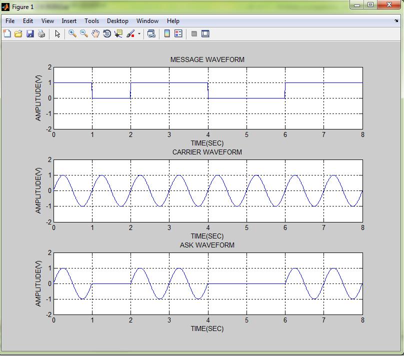
20 DATE: AMPLITUDE SHIFT KEYING AIM: To perform Amplitude Shift Keying modulation and demodulation techniques and to plot its wave form characteristics. APPARATUS REQUIRED: S NO APPARATUS QUANTITY Data formatting and carrier modulation trainer kit Power chord CRO THEORY: Amplitude-Shift Keying (ASK) is a form of amplitude modulation that represents digital data as variations in the amplitude of a carrier wave. In an ASK system, the binary symbol 1 is represented by transmitting a fixed-amplitude carrier wave and fixed frequency for a bit duration of T seconds. If the signal value is 1 then the carrier signal will be transmitted; otherwise, a signal value of 0 will be transmitted. ASK operates as a switch, using the presence of a carrier wave to indicate a binary one and its absence to indicate a binary zero. This type of modulation is called On-Off Keying (OOK), and is used at radio frequencies.
 Time in ms Modulated Signal Time in ms Demodulated Signal Time in ms")
21 Model Graph: Message Signal Time in ms Carrier Signal Amplitude in volts (V) Time in ms Modulated Signal Time in ms Demodulated Signal Time in ms
22 PROCEDURE: 1. Connections are made as per the circuit diagram. 2. Switch on the trainer kit. 3. Connect the signal input and carrier input to the modulator circuit. 4. Observe the output on CRO. 5. Note down the amplitude and frequency of the input. 6. Note down the amplitude and frequency of the ASK output. 7. Obtain the amplitude and frequency of the demodulated output.
23 TABULATION: Name of the Signal Amplitude (Volts) Time Period (seconds)
24 RESULT:

25 BLOCK DIAGRAM FREQUENCY SHIFT KEYING
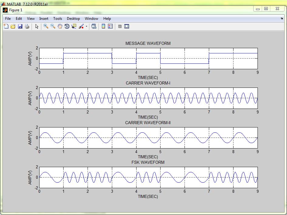
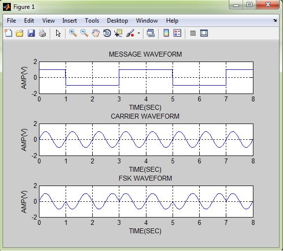
26 EXP.NO: DATE: FREQUENCY SHIFT KEYING AIM: To perform Frequency Shift Keying modulation and demodulation techniques and to plot its wave form characteristics. APPARATUS REQUIRED: S NO APPARATUS QUANTITY Data formatting and carrier modulation trainer kit Power chord CRO THEORY: Frequency Shift Keying (FSK) is one of several techniques used to transmit a digital signal on an analogue transmission medium. The frequency of a sine wave carrier is shifted up or down to represent either a single binary value or a specific bit pattern. The simplest form of frequency shift keying is called Binary Frequency Shift Keying(BFSK), in which the binary logic values one and zero are represented by the carrier frequency being shifted above or below the centre frequency. In conventional BFSK systems, the higher frequency represents a logic high (one) and is referred to as the mark frequency. The lower frequency represents a logic low (zero) and is called the spacefrequency. The two frequencies are equi-distant from the centre frequency.

27 MODEL GRAPH: Time in ms Amplitude in volts(v) Time in ms Time in ms Time in ms Demodulated Signal
28 PROCEDURE: 1. Connections are made as per the circuit diagram. 2. Switch on the trainer kit. 3. Connect the signal input and carrier input to the modulator circuit. 4. Observe the output on CRO. 5. Note down the amplitude and frequency of the input. 6. Note down the amplitude and frequency of the FSK output. 7. Obtain the amplitude and frequency of the demodulated output.
29 TABULATION: Name of the Signal Amplitude (Volts) Time Period (seconds)
30 RESULT:

31 BLOCK DIAGRAM PHASE SHIFT KEYING
32 EXP.NO: DATE: PHASE SHIFT KEYING AIM: To Perform Phase Shift Keying modulation and demodulation techniques and to plot its wave form characteristics. APPARATUS REQUIRED: S NO APPARATUS QUANTITY Data formatting and carrier modulation trainer kit Power chord CRO THEORY: PHASE SHIFT KEYING: Phase-shift keying (PSK) is a method of digital communication in which the phase of a transmitted signal is varied to convey information. The simplest PSK technique is called Binary Phase-Shift Keying (BPSK). It uses two opposite signal phases (0 and 180 degrees). The digital signal is broken up timewise into individual bits (binary digits). The state of each bit is determined according to the state of the preceding bit. If the phase of the wave does not change, then the signal state stays the same (0 or 1). If the phase of the wave changes by 180 degrees that is, if the phase reverses then the signal state changes (from 0 to 1, or from 1 to 0). Because there are two possible wave phases, BPSK is sometimes called biphase modulation.
33 MODEL GRAPH MESSAGE SIGNAL Time in ms CARRIER SIGNAL Amplitude in volts(v) Time in ms PSK MODULATED SIGNAL Time in ms DEMODULATED SIGNAL Time in ms
34 PROCEDURE: 1. Connections are made as per the circuit diagram. 2. Switch on the trainer kit. 3. Connect the signal input and carrier input to the modulator circuit. 4. Observe the output on CRO. 5. Note down the amplitude and frequency of the input. 6. Note down the amplitude and frequency of the PSK output. 7. Obtain the amplitude and frequency of the demodulated output.
35 TABULATION: Name of the Signal Amplitude (Volts) Time Period (seconds)
36 RESULT:

37 BLOCK DIAGRAM QUADRATURE PHASE SHIFT KEYING
38 EXP.NO: DATE: QUADRATURE PHASE SHIFT KEYING AIM: To perform Quadrature Phase Shift Keying modulation and demodulation techniques and to plot its wave form characteristics. APPARATUS REQUIRED: S NO APPARATUS QUANTITY Data formatting and carrier modulation trainer kit Power chord CRO THEORY: QUADRATURE PHASE SHIFT KEYING: Quadrature Phase Shift Keying (QPSK) is the digital modulation technique.quadrature Phase Shift Keying (QPSK) is a form of Phase Shift Keying in which two bits are modulated at once, selecting one of four possible carrier phase shifts (0, Π/2, Π, and 3Π/2). QPSK perform by changing the phase of the In-phase (I) carrier from 0 to 180 and the Quadrature-phase (Q) carrier between 90 and 270. This is used to indicate the four states of a 2-bit binary code. Each state of these carriers is referred to as a Symbol. QPSK perform by changing the phase of the In-phase (I) carrier from 0 to 180 and the Quadrature-phase (Q) carrier between 90 and 270. This is used to indicate the four states of a 2-bit binary code. Each state of these carriers is referred to as a Symbol. Quadrature Phase-shift Keying (QPSK) is a widely used method of transferring digital data by changing or modulating the phase of a carrier signal. In QPSK digital data is represented by 4 points around a circle which correspond to 4 phases of the carrier signal. These points are called symbols.
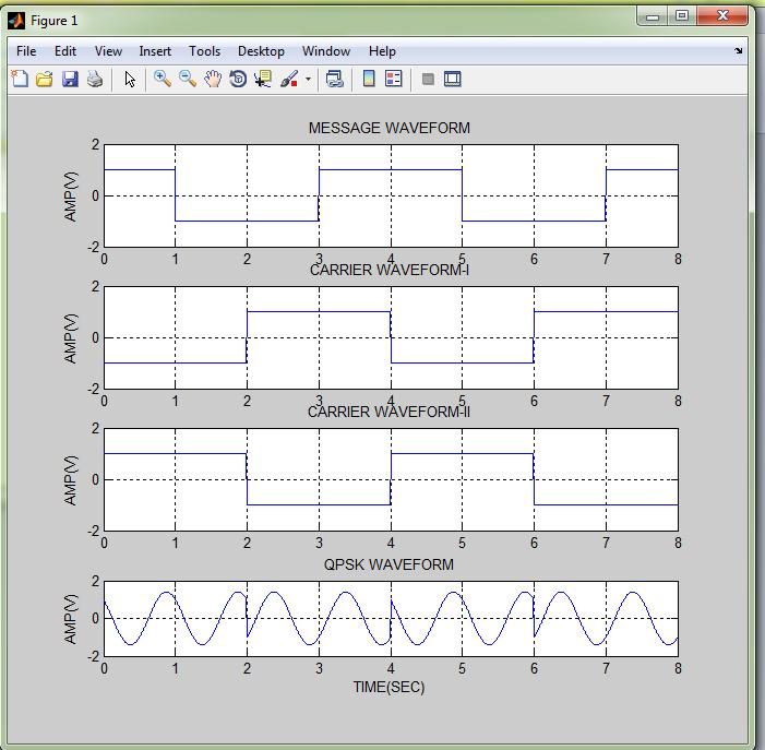
39 MODEL GRAPH:
40 PROCEDURE: 1. Connections are made as per the circuit diagram. 2. Switch on the trainer kit. 3. Connect the signal input and carrier input to the modulator circuit. 4. Observe the output on CRO. 5. Note down the amplitude and frequency of the input. 6. Note down the amplitude and frequency of the QPSK output. 7. Obtain the amplitude and frequency of the demodulated output.
41 TABULATION: Name of the Signal Amplitude (Volts) Time Period (seconds)
42 RESULT:
43 EXP.NO: DATE: GENERATION AND DETECTION OF DIGITAL MODULATION TECHNIQUE USING MATLAB AIM:- To plot the wave form for Binary Amplitude Shift Keying (BASK) signal using MATLAB for a stream of bits. SOFTWARE USED: MATLAB 7.1 THEORY: AMPLITUDE SHIFT KEYING: Amplitude-Shift Keying (ASK) is a form of amplitude modulation that represents digital data as variations in the amplitude of a carrier wave. In an ASK system, the binary symbol 1 is represented by transmitting a fixed-amplitude carrier wave and fixed frequency for a bit duration of T seconds. If the signal value is 1 then the carrier signal will be transmitted; otherwise, a signal value of 0 will be transmitted. FREQUENCY SHIFT KEYING: Frequency Shift Keying (FSK) is one of several techniques used to transmit a digital signal on an analogue transmission medium. The frequency of a sine wave carrier is shifted up or down to represent either a single binary value or a specific bit pattern. The simplest form of frequency shift keying is called Binary Frequency Shift Keying(BFSK), in which the binary logic values one and zero are represented by the carrier frequency being shifted above or below the centre frequency. PHASE SHIFT KEYING: Phase-shift keying (PSK) is a method of digital communication in which the phase of a transmitted signal is varied to convey information.the simplest PSK technique is called Binary Phase-Shift Keying (BPSK). It uses two opposite signal phases (0 and 180 degrees). The digital signal is broken up timewise into individual bits (binary digits). QUADRATURE PHASE SHIFT KEYING: Quadrature Phase Shift Keying (QPSK) is the digital modulation technique.quadrature Phase Shift Keying (QPSK) is a form of Phase Shift Keying in which two bits are modulated at once, selecting one of four possible carrier phase shifts (0, Π/2, Π, and 3Π/2). QPSK perform by changing the phase of the In-phase (I) carrier from 0 to 180 and the Quadrature-phase (Q) carrier between 90 and 270. This is used to indicate the four states of a 2-bit binary code. Each state of these carriers is referred to as a Symbol.
44 ALGORITHM: ASK: Step 1:Get the input values. Step 2:Plot the values on the corresponding axis. Step 3:Perform the ASK operation. Step 4:Output values are displayed in the command window. Step 5:The required waveforms are displayed in the output window(figure 1). FSK: Step 1:Get the input values. Step 2:Plot the values on the corresponding axis. Step 3:Perform the FSK operation. Step 4:Output values are displayed in the command window. Step 5:The required waveforms are displayed in the output window(figure 2). PSK: Step 1:Get the input values. Step 2:Plot the values on the corresponding axis. Step 3:Perform the PSK operation. Step 4:Output values are displayed in the command window. Step 5:The required waveforms are displayed in the output window(figure 3). QPSK: Step 1:Get the input values. Step 2:Plot the values on the corresponding axis. Step 3:Perform the QPSK operation. Step 4:Output values are displayed in the command window. Step 5:The required waveforms are displayed in the output window(figure 4).
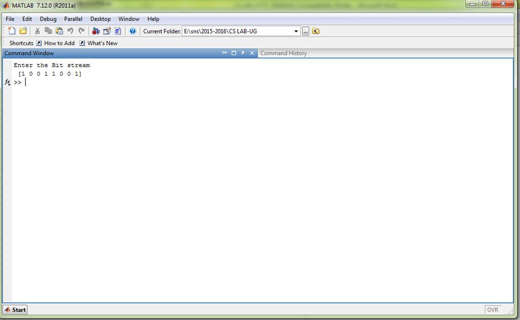
45 ASK - MATLAB PROGRAM:- clear; clc; b = input('enter the Bit stream \n '); %b = [ ]; n = length(b); t = 0:.01:n; x = 1:1:(n+1)*100; for i = 1:n for j = i:.1:i+1 bw(x(i*100:(i+1)*100)) = b(i); end end bw = bw(100:end); sint = sin(2*pi*t); st = bw.*sint; subplot(3,1,1) plot(t,bw) grid on ; axis([0 n -2 +2]) subplot(3,1,2) plot(t,sint) grid on ; axis([0 n -2 +2]) subplot(3,1,3) plot(t,st) grid on ; axis([0 n -2 +2])
46 OUTPUT:
47 FSK - MATLAB PROGRAM:- clear; clc; b = input('enter the Bit stream \n '); %b = [ ]; n = length(b); t = 0:.01:n; x = 1:1:(n+1)*100; for i = 1:n if (b(i) == 0) b_p(i) = -1; else b_p(i) = 1; end for j = i:.1:i+1 bw(x(i*100:(i+1)*100)) = b_p(i); end end bw = bw(100:end); wo = 2*(2*pi*t); W = 1*(2*pi*t); sinht = sin(wo+w); sinlt = sin(wo-w); st = sin(wo+(bw).*w); subplot(4,1,1) plot(t,bw) grid on ; axis([0 n -2 +2]) subplot(4,1,2) plot(t,sinht) grid on ; axis([0 n -2 +2]) subplot(4,1,3) plot(t,sinlt) grid on ; axis([0 n -2 +2]) subplot(4,1,4) plot(t,st) grid on ; axis([0 n -2 +2]) Fs=1; figure %pburg(st,10) periodogram(st)
48 OUTPUT:
49 PSK - MATLAB PROGRAM:- clear; clc; b = input('enter the Bit stream \n '); %b = [ ]; n = length(b); t = 0:.01:n; x = 1:1:(n+1)*100; for i = 1:n if (b(i) == 0) b_p(i) = -1; else b_p(i) = 1; end for j = i:.1:i+1 bw(x(i*100:(i+1)*100)) = b_p(i); end end bw = bw(100:end); sint = sin(2*pi*t); st = bw.*sint; subplot(3,1,1) plot(t,bw) grid on ; axis([0 n -2 +2]) subplot(3,1,2) plot(t,sint) grid on ; axis([0 n -2 +2]) subplot(3,1,3) plot(t,st) grid on ; axis([0 n -2 +2])
50 OUTPUT:
51 QPSK - MATLAB PROGRAM:- clear; clc; b = input('enter the Bit stream \n '); %b = [ ]; n = length(b); t = 0:.01:n; x = 1:1:(n+2)*100; for i = 1:n if (b(i) == 0) b_p(i) = -1; else b_p(i) = 1; end for j = i:.1:i+1 bw(x(i*100:(i+1)*100)) = b_p(i); if (mod(i,2) == 0) bow(x(i*100:(i+1)*100)) = b_p(i); bow(x((i+1)*100:(i+2)*100)) = b_p(i); else bew(x(i*100:(i+1)*100)) = b_p(i); bew(x((i+1)*100:(i+2)*100)) = b_p(i); end if (mod(n,2)~= 0) bow(x(n*100:(n+1)*100)) = -1; bow(x((n+1)*100:(n+2)*100)) = -1; end end end %be = b_p(1:2:end); %bo = b_p(2:2:end); bw = bw(100:end); bew = bew(100:(n+1)*100); bow = bow(200:(n+2)*100); cost = cos(2*pi*t); sint = sin(2*pi*t); st = bew.*cost+bow.*sint; 18 subplot(4,1,1) plot(t,bw) grid on ; axis([0 n -2 +2]) subplot(4,1,2) plot(t,bow) grid on ; axis([0 n -2 +2]) subplot(4,1,3) plot(t,bew) grid on ; axis([0 n -2 +2]) subplot(4,1,4) plot(t,st) grid on ; axis([0 n -2 +2])
52 OUTPUT:
53 RESULT:
54 EXP.NO: DATE : IMPLEMENTATION OF LINEAR BLOCK CODES AIM: To implement linear block codes using MATLAB. APPARATUS REQUIRED: MATLAB 7.1 THEORY: Code words are produced on a block by block basis called as linear block codes.code word is a sequence of symbols.encoded block of `n` bits is called a code word.the sum of two code words belonging to the code.the all zero word is always a code word.the minimum distance between two code words of a linear code is equal to the minimum weight of the code. ALGORITHM: Step 1:Assign block length n=7 and message bit k=7. Step 2:Define message and parity matrix. Step 3:Generate generator matrix of the form [p:in-k]. Step 4:Multiply each generator matrix row with message column. Step 5:Linear code is obtained by doing XOR operation with output of matrix formed in step 4.
55 PROGRAM: clc; clear all; close all; % input generator matrix g=input('enter the generator matrix:'); disp('g=') disp('the order of linear block code for given generator matrix is :') [n,k]=size(transpose(g)) for i=1:2^k for j=k:-1:1 if rem(i-1,2^ (-j+k+1))>=2^(-j+k) u(i,j)=1; else u(i,j)=0; end end end u; disp('the possible code words are:') c=rem(u*g,2) disp('the minimum hamming distance d_min for given block code is:') d_min=min(sum((c(2:2^k,:))')) % code word r=input('enter the received code word:') p=[g(:,n-k+2:n)]; h=[transpose(p),eye(n-k)]; disp('hamming code') ht=transpose(h) disp('syndrome of given code word is') s=rem(r*ht,2) for i=1:1:size(ht) if(ht(i,1:3)==s) r(i)=1-r(i); break; end end disp('error s in bit:') i disp('the corrected code word s:') r
56 MANUAL CALCULATION FOR LINEAR BLOCK CODE
57 OUTPUT: enter the generator matrix:[ ; ; ; ] G= the order of linear block code for given generator matrix is : n = 7 k = 4 the possible code words are: c =
58 the minimum hamming distance d_min for given block code is: d_min = 3 enter the received code word:[ ] r = hamming code ht =
59 syndrome of given code word is s = error s in bit: i = 3 the corrected code word s: r =
60 RESULT:
61 EXP.NO: DATE : CHANNEL EQUALIZER DESIGN USING MATLAB AIM: To design a channel equalizer using LMS algorithm in MATLAB. APPARATUS REQUIRED: MATLAB 7.1 THEORY: CHANNEL EQUALISER Channel equaliser is used to reduce inter symbol interference, in digital communication. Equalisation is done with the help of the Filter. Here we use the Adaptive equaliser. ADAPTIVE EQUALISER An adaptive equalizer is an equalizer that automatically adapts to time-varying properties of the communication channel. Many adaptation strategies exists among them, we see LMS: Here the receiver does not have access to the transmitted signal x when it is not in training mode. If the probability that the equalizer makes a mistake is sufficiently small, the symbol decisions d(n) made by the equalizer may be substituted for x. RLS: A well-known example is the decision feedback equalizer, a filter that uses feedback of detected symbols in addition to conventional equalization of future symbols. Some systems use predefined training sequences to provide reference points for the adaptation process. LEAST MEAN SQUARES (LMS) LMS algorithms are a class of adaptive filter used to mimic a desired filter by finding the filter coefficients that relate to producing the least mean squares of the error signal (difference between the desired and the actual signal). It is a stochastic gradient descent method in that the filter is only adapted based on the error at the current time.
62 ALGORITHM: Step 1:Initialization of all variables and parameters. Step 2:Generate input sinusoidal signals. Step 3:Generate noise signal using random function. Step 4:Add input signal and noise signal. Step 5:Calculate the output,bit error rate and SNR. Step 6:Plot the LMS output waveform.
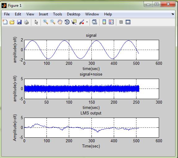
63 PROGRAM: clc; clear all; close all; w=0; L=512; M=1024; G=256; 1=[0:L-1]; fs=10000; f0=70; w(:,1)=[0:0]; mu=0.0125; x1=sin(2*pi*f0*[0:l-1]/fs); x2=sin(2*pi*f0*[0:l-1]/fs); pp=1; x6=0; while pp<10 x3=(x1+x2)+0.09*randn; x6=x6+x3; pp=pp+1; end x6=x6/10; subplot(3,1,1) plot(x6) grid title( signal ) xlabel( time(sec) ) ylabel( amplitude(volt) ) x=0.5*randn(g,l); subplot(3,1,2) plot(x, b ) grid title( signal+noise ) xlabel( time(sec) ) ylabel( amplitude(volt) ) for j=1:g
64 for i=1:l y(j,i)=w(:,i) +[x3(i)*randn*0.09]; e(j,i)=x(j,i)-y(j,i); w(:,i+1)=w(:,i)+2*0.0125*e(j,i)+[x3(i)*randn*0.09]; end EE(j,:)=(fft(e(j,:),M)); end u=(sum(abs(ee).^2)/(g))/max((sum(abs(ee).^2)/(g))); w=w(1:512); subplot(3,1,3) plot(w) grid title( LMS output ) xlabel( time(sec) ) ylabel( amplitude(volt) ) xg=(sum((x3-w)))/(length(x3)); BER=abs(xg) sn=max(u); nn=max(x3); SNR=nn/sn
65 OUTPUT:
66 RESULT:
Department of Electronics & Telecommunication Engg. LAB MANUAL. B.Tech V Semester [ ] (Branch: ETE)
![Department of Electronics & Telecommunication Engg. LAB MANUAL. B.Tech V Semester [ ] (Branch: ETE)](/thumbs/86/93078052.jpg "Department of Electronics & Telecommunication Engg. LAB MANUAL. B.Tech V Semester [ ] (Branch: ETE)") Department of Electronics & Telecommunication Engg. LAB MANUAL SUBJECT:-DIGITAL COMMUNICATION SYSTEM [BTEC-501] B.Tech V Semester [2013-14] (Branch: ETE) KCT COLLEGE OF ENGG & TECH., FATEHGARH PUNJAB TECHNICAL
Department of Electronics & Telecommunication Engg. LAB MANUAL SUBJECT:-DIGITAL COMMUNICATION SYSTEM [BTEC-501] B.Tech V Semester [2013-14] (Branch: ETE) KCT COLLEGE OF ENGG & TECH., FATEHGARH PUNJAB TECHNICAL
COMPUTER COMMUNICATION AND NETWORKS ENCODING TECHNIQUES
 COMPUTER COMMUNICATION AND NETWORKS ENCODING TECHNIQUES Encoding Coding is the process of embedding clocks into a given data stream and producing a signal that can be transmitted over a selected medium.
Communication Systems Lab
 LAB MANUAL Communication Systems Lab (EE-226-F) Prepared by: Varun Sharma (Lab In-charge) Dayal C. Sati (Faculty In-charge) B R C M CET BAHAL DEPARTMENT OF ELECTRONICS & COMMUNICATION ENGINEERING Page
SEN366 Computer Networks
 SEN366 Computer Networks Prof. Dr. Hasan Hüseyin BALIK (5 th Week) 5. Signal Encoding Techniques 5.Outline An overview of the basic methods of encoding digital data into a digital signal An overview of
Digital to Digital Encoding
 MODULATION AND ENCODING Data must be transformed into signals to send them from one place to another Conversion Schemes Digital-to-Digital Analog-to-Digital Digital-to-Analog Analog-to-Analog Digital to
CTD600 Communication Trainer kit
 kit Digital RELATED PRODUCTS v Analog s v Optical Fibers s v Digital and Analog s v Communication Electronic Trainers v Function Generator and Power Supply v Multiple Signal Generator and 1 Line Code 2
Year : TYEJ Sub: Digital Communication (17535) Assignment No. 1. Introduction of Digital Communication. Question Exam Marks
 Assignment No. 1. Introduction of Digital Communication. Question Exam Marks") Assignment 1 Introduction of Digital Communication Sr. Question Exam Marks 1 Draw the block diagram of the basic digital communication system. State the function of each block in detail. W 2015 6 2 State
Assignment 1 Introduction of Digital Communication Sr. Question Exam Marks 1 Draw the block diagram of the basic digital communication system. State the function of each block in detail. W 2015 6 2 State
Class 4 ((Communication and Computer Networks))
)") Class 4 ((Communication and Computer Networks)) Lesson 5... SIGNAL ENCODING TECHNIQUES Abstract Both analog and digital information can be encoded as either analog or digital signals. The particular encoding
Class 4 ((Communication and Computer Networks)) Lesson 5... SIGNAL ENCODING TECHNIQUES Abstract Both analog and digital information can be encoded as either analog or digital signals. The particular encoding
Department of Electronics & Communication Engineering LAB MANUAL
 Department of Electronics & Communication Engineering LAB MANUAL SUBJECT: DIGITAL COMMUNICATION [06BEC201] B.Tech III Year VI Semester (Branch: ECE) BHAGWANT UNIVERSITY SIKAR ROAD, AJMER DIGITAL COMMUNICATION
BINARY AMPLITUDE SHIFT KEYING
 BINARY AMPLITUDE SHIFT KEYING AIM: To set up a circuit to generate Binary Amplitude Shift keying and to plot the output waveforms. COMPONENTS AND EQUIPMENTS REQUIRED: IC CD4016, IC 7474, Resistors, Zener
CHAPTER 2. Instructor: Mr. Abhijit Parmar Course: Mobile Computing and Wireless Communication ( )
") CHAPTER 2 Instructor: Mr. Abhijit Parmar Course: Mobile Computing and Wireless Communication (2170710) Syllabus Chapter-2.3 Modulation Techniques Reasons for Choosing Encoding Techniques Digital data,
CHAPTER 2 Instructor: Mr. Abhijit Parmar Course: Mobile Computing and Wireless Communication (2170710) Syllabus Chapter-2.3 Modulation Techniques Reasons for Choosing Encoding Techniques Digital data,
Department of Electronics and Communication Engineering 1
 UNIT I SAMPLING AND QUANTIZATION Pulse Modulation 1. Explain in detail the generation of PWM and PPM signals (16) (M/J 2011) 2. Explain in detail the concept of PWM and PAM (16) (N/D 2012) 3. What is the
Department of Electronics & Communication Engineering LAB MANUAL SUBJECT: DIGITAL COMMUNICATION LABORATORY [ECE324] (Branch: ECE)
![Department of Electronics & Communication Engineering LAB MANUAL SUBJECT: DIGITAL COMMUNICATION LABORATORY [ECE324] (Branch: ECE)](/thumbs/96/127341232.jpg "Department of Electronics & Communication Engineering LAB MANUAL SUBJECT: DIGITAL COMMUNICATION LABORATORY [ECE324] (Branch: ECE)") Department of Electronics & Communication Engineering LAB MANUAL SUBJECT: DIGITAL COMMUNICATION LABORATORY [ECE324] B.Tech Year 3 rd, Semester - 5 th (Branch: ECE) Version: 01 st August 2018 The LNM Institute
Department of Electronics & Communication Engineering LAB MANUAL SUBJECT: DIGITAL COMMUNICATION LABORATORY [ECE324] B.Tech Year 3 rd, Semester - 5 th (Branch: ECE) Version: 01 st August 2018 The LNM Institute
Dharmapuri LAB MANUAL. Regulation : Branch : B.E. ECE 12- COMMUNICATION SYSTEMS LABORATORY EC6512
 Dharmapuri 636 703. LAB MANUAL Regulation : 2013 Branch Year & Semester : B.E. ECE : III Year / V Semester EC6512 12- COMMUNICATION SYSTEMS LABORATORY INTRODUCTION Exchanging information between two systems
DIGITAL COMMUNICATION
 DIGITAL COMMUNICATION TRAINING LAB Digital communication has emerged to augment or replace the conventional analog systems, which had been used widely a few decades back. Digital communication has demonstrated
DIGITAL COMMUNICATIONS LAB
 DIGITAL COMMUNICATIONS LAB List of Experiments: 1. PCM Generation and Detection. 2. Differential Pulse Code modulation. 3. Delta modulation. 4. Time Division Multiplexing of 2band Limited Signals. 5. Frequency
UNIT TEST I Digital Communication
 Time: 1 Hour Class: T.E. I & II Max. Marks: 30 Q.1) (a) A compact disc (CD) records audio signals digitally by using PCM. Assume the audio signal B.W. to be 15 khz. (I) Find Nyquist rate. (II) If the Nyquist
 Department Of ECE III Year / V Semester EC 6512 COMMUNICATION SYSTEM LABORATORY LAB MANUAL SYLLABUS EC6512 COMMUNICATION SYSTEMLABORATORY LIST OF EXPERIMENTS: CYCLE: 1 1. Signal Sampling and reconstruction
Digital signal is denoted by discreet signal, which represents digital data.there are three types of line coding schemes available:
 Digital-to-Digital Conversion This section explains how to convert digital data into digital signals. It can be done in two ways, line coding and block coding. For all communications, line coding is necessary
Lecture 3 Concepts for the Data Communications and Computer Interconnection
 Lecture 3 Concepts for the Data Communications and Computer Interconnection Aim: overview of existing methods and techniques Terms used: -Data entities conveying meaning (of information) -Signals data
DIGITAL COMMUNICATIONS
 DIGITAL COMMUNICATIONS LAB MANUAL (STUDENT COPY) DEPARTMENT OF ELECTRONICS AND COMMUNICATION ENGINEERING GUDLAVALLERU ENGINEERING COLLEGE SESHADRI RAO KNOWLEDGE VILLAGE::GUDLAVALLERU INDEX S.NO. NAME OF
Engr M. Hadi Ali Khan B. Sc. Engg (AMU), MIETE (India), Ex-MIEEE (USA), Ex-MSSI (India)
, MIETE (India), Ex-MIEEE (USA), Ex-MSSI (India)") Page 1 of 26 Department of Electronics Engineering, Communication Systems Laboratory Laboratory Manual for B. Tech. (Electronics), III Year (VI Semester) Lab Course EL 394 ( Communication Lab. II) List
Page 1 of 26 Department of Electronics Engineering, Communication Systems Laboratory Laboratory Manual for B. Tech. (Electronics), III Year (VI Semester) Lab Course EL 394 ( Communication Lab. II) List
EXPERIMENT WISE VIVA QUESTIONS
 EXPERIMENT WISE VIVA QUESTIONS Pulse Code Modulation: 1. Draw the block diagram of basic digital communication system. How it is different from analog communication system. 2. What are the advantages of
QUESTION BANK SUBJECT: DIGITAL COMMUNICATION (15EC61)
") QUESTION BANK SUBJECT: DIGITAL COMMUNICATION (15EC61) Module 1 1. Explain Digital communication system with a neat block diagram. 2. What are the differences between digital and analog communication systems?
QUESTION BANK SUBJECT: DIGITAL COMMUNICATION (15EC61) Module 1 1. Explain Digital communication system with a neat block diagram. 2. What are the differences between digital and analog communication systems?
The figures and the logic used for the MATLAB are given below.
 MATLAB FIGURES & PROGRAM LOGIC: Transmitter: The figures and the logic used for the MATLAB are given below. Binary Data Sequence: For our project we assume that we have the digital binary data stream.
UNIT I Source Coding Systems
 SIDDHARTH GROUP OF INSTITUTIONS: PUTTUR Siddharth Nagar, Narayanavanam Road 517583 QUESTION BANK (DESCRIPTIVE) Subject with Code: DC (16EC421) Year & Sem: III-B. Tech & II-Sem Course & Branch: B. Tech
Digital Communication
 Digital Communication Laboratories bako@ieee.org DigiCom Labs There are 5 labs related to the digital communication. Study of the parameters of metal cables including: characteristic impendance, attenuation
KINGS COLLEGE OF ENGINEERING DEPARTMENT OF ELECTRONICS AND COMMUNICATION ENGINEERING QUESTION BANK. Subject Name: Digital Communication Techniques
 KINGS COLLEGE OF ENGINEERING DEPARTMENT OF ELECTRONICS AND COMMUNICATION ENGINEERING QUESTION BANK Subject Code: EC1351 Year/Sem: III/IV Subject Name: Digital Communication Techniques UNIT I PULSE MODULATION
Signal Encoding Techniques
 2 Techniques ITS323: to Data Communications CSS331: Fundamentals of Data Communications Sirindhorn International Institute of Technology Thammasat University Prepared by Steven Gordon on 3 August 2015
Data Communications and Networking (Module 2)
") Data Communications and Networking (Module 2) Chapter 5 Signal Encoding Techniques References: Book Chapter 5 Data and Computer Communications, 8th edition, by William Stallings 1 Outline Overview Encoding
Data Communications and Networking (Module 2) Chapter 5 Signal Encoding Techniques References: Book Chapter 5 Data and Computer Communications, 8th edition, by William Stallings 1 Outline Overview Encoding
1 Analog and Digital Communication Lab
 1 2 Amplitude modulator trainer kit diagram AM Detector trainer kit Diagram 3 4 Calculations: 5 Result: 6 7 8 Balanced modulator circuit diagram Generation of DSB-SC 1. For the same circuit apply the modulating
EEE 309 Communication Theory
 EEE 309 Communication Theory Semester: January 2017 Dr. Md. Farhad Hossain Associate Professor Department of EEE, BUET Email: mfarhadhossain@eee.buet.ac.bd Office: ECE 331, ECE Building Types of Modulation
Amplitude modulator trainer kit diagram
 Amplitude modulator trainer kit diagram AM Detector trainer kit Diagram Calculations: Result: Pre lab test (20) Observation (20) Simulation (20) Remarks & Signature with Date Circuit connection (30) Result
Chapter 4 Digital Transmission 4.1
 Chapter 4 Digital Transmission 4.1 Copyright The McGraw-Hill Companies, Inc. Permission required for reproduction or display. 4-1 DIGITAL-TO-DIGITAL CONVERSION In this section, we see how we can represent
Chapter 5: Modulation Techniques. Abdullah Al-Meshal
 Chapter 5: Modulation Techniques Abdullah Al-Meshal Introduction After encoding the binary data, the data is now ready to be transmitted through the physical channel In order to transmit the data in the
CHAPTER 3 Syllabus (2006 scheme syllabus) Differential pulse code modulation DPCM transmitter
 Differential pulse code modulation DPCM transmitter") CHAPTER 3 Syllabus 1) DPCM 2) DM 3) Base band shaping for data tranmission 4) Discrete PAM signals 5) Power spectra of discrete PAM signal. 6) Applications (2006 scheme syllabus) Differential pulse code
CHAPTER 3 Syllabus 1) DPCM 2) DM 3) Base band shaping for data tranmission 4) Discrete PAM signals 5) Power spectra of discrete PAM signal. 6) Applications (2006 scheme syllabus) Differential pulse code
KINGS DEPARTMENT OF ELECTRONICS AND COMMUNICATION ENGINEERING DIGITAL COMMUNICATION TECHNIQUES YEAR/SEM: III / VI BRANCH : ECE PULSE MODULATION
 KINGS COLLEGE OF ENGINEERING DEPARTMENT OF ELECTRONICS AND COMMUNICATION ENGINEERING SUB.NAME : EC1351 DIGITAL COMMUNICATION TECHNIQUES BRANCH : ECE YEAR/SEM: III / VI UNIT I PULSE MODULATION PART A (2
COSC 3213: Computer Networks I: Chapter 3 Handout #4. Instructor: Dr. Marvin Mandelbaum Department of Computer Science York University Section A
 COSC 3213: Computer Networks I: Chapter 3 Handout #4 Instructor: Dr. Marvin Mandelbaum Department of Computer Science York University Section A Topics: 1. Line Coding: Unipolar, Polar,and Inverted ; Bipolar;
Swedish College of Engineering and Technology Rahim Yar Khan
 PRACTICAL WORK BOOK Telecommunication Systems and Applications (TL-424) Name: Roll No.: Batch: Semester: Department: Swedish College of Engineering and Technology Rahim Yar Khan Introduction Telecommunication
Signal Encoding Techniques
 Signal Encoding Techniques Overview Have already noted previous chapters that both analog and digital information can be encoded as either analog or digital signals: Digital data, digital signals: simplest
 Sixth Semester B.E. Degree Examination, May/June 2010 Digital Communication Note: Answer any FIVEfull questions, selecting at least TWO questionsfrom each part. PART-A a. With a block diagram, explain
QUESTION BANK EC 1351 DIGITAL COMMUNICATION YEAR / SEM : III / VI UNIT I- PULSE MODULATION PART-A (2 Marks) 1. What is the purpose of sample and hold
 1. What is the purpose of sample and hold") QUESTION BANK EC 1351 DIGITAL COMMUNICATION YEAR / SEM : III / VI UNIT I- PULSE MODULATION PART-A (2 Marks) 1. What is the purpose of sample and hold circuit 2. What is the difference between natural sampling
QUESTION BANK EC 1351 DIGITAL COMMUNICATION YEAR / SEM : III / VI UNIT I- PULSE MODULATION PART-A (2 Marks) 1. What is the purpose of sample and hold circuit 2. What is the difference between natural sampling
Thus there are three basic modulation techniques: 1) AMPLITUDE SHIFT KEYING 2) FREQUENCY SHIFT KEYING 3) PHASE SHIFT KEYING
 AMPLITUDE SHIFT KEYING 2) FREQUENCY SHIFT KEYING 3) PHASE SHIFT KEYING") CHAPTER 5 Syllabus 1) Digital modulation formats 2) Coherent binary modulation techniques 3) Coherent Quadrature modulation techniques 4) Non coherent binary modulation techniques. Digital modulation formats:
CHAPTER 5 Syllabus 1) Digital modulation formats 2) Coherent binary modulation techniques 3) Coherent Quadrature modulation techniques 4) Non coherent binary modulation techniques. Digital modulation formats:
Digital Modulation Lecture 01. Review of Analogue Modulation Introduction to Digital Modulation Techniques Richard Harris
 Digital Modulation Lecture 01 Review of Analogue Modulation Introduction to Digital Modulation Techniques Richard Harris Objectives You will be able to: Classify the various approaches to Analogue Modulation
Objectives. Presentation Outline. Digital Modulation Lecture 01
 Digital Modulation Lecture 01 Review of Analogue Modulation Introduction to Digital Modulation Techniques Richard Harris Objectives You will be able to: Classify the various approaches to Analogue Modulation
BAPATLA ENGINEERING COLLEGE DIGITAL COMMUNICATIONS LAB EC-451. PREPARED BY S. Pallaviram, Lecturer
 BAPATLA ENGINEERING COLLEGE DIGITAL COMMUNICATIONS LAB EC-451 PREPARED BY S. Pallaviram, Lecturer Department of Electronics and Communications Engineering Bapatla Engineering College (Affiliated to Acharya
Digital Communication (650533) CH 3 Pulse Modulation
 CH 3 Pulse Modulation") Philadelphia University/Faculty of Engineering Communication and Electronics Engineering Digital Communication (650533) CH 3 Pulse Modulation Instructor: Eng. Nada Khatib Website: http://www.philadelphia.edu.jo/academics/nkhatib/
Philadelphia University/Faculty of Engineering Communication and Electronics Engineering Digital Communication (650533) CH 3 Pulse Modulation Instructor: Eng. Nada Khatib Website: http://www.philadelphia.edu.jo/academics/nkhatib/
Dhanalakshmi College of Engineering Manimangalam, Tambaram, Chennai
 Dhanalakshmi College of Engineering Manimangalam, Tambaram, Chennai 601 301 DEPARTMENT OF ELECTRONICS AND COMMUNICATION ENGINEERING V SEMESTER - R 2013 EC6512 COMMUNICATION SYSTEMS LABORATORY LABORATORY
Digital Modulation Schemes
 Digital Modulation Schemes 1. In binary data transmission DPSK is preferred to PSK because (a) a coherent carrier is not required to be generated at the receiver (b) for a given energy per bit, the probability
EEE 309 Communication Theory
 EEE 309 Communication Theory Semester: January 2016 Dr. Md. Farhad Hossain Associate Professor Department of EEE, BUET Email: mfarhadhossain@eee.buet.ac.bd Office: ECE 331, ECE Building Part 05 Pulse Code
Data Encoding g(p (part 2)
") Data Encoding g(p (part 2) CSE 3213 Instructor: U.T. Nguyen 10/11/2007 12:44 PM 1 Analog Data, Digital Signals (5.3) 2 1 Analog Data, Digital Signals Digitization Conversion of analog data into digital
Data Encoding g(p (part 2) CSE 3213 Instructor: U.T. Nguyen 10/11/2007 12:44 PM 1 Analog Data, Digital Signals (5.3) 2 1 Analog Data, Digital Signals Digitization Conversion of analog data into digital
Downloaded from 1
 VII SEMESTER FINAL EXAMINATION-2004 Attempt ALL questions. Q. [1] How does Digital communication System differ from Analog systems? Draw functional block diagram of DCS and explain the significance of
Datacommunication I. Layers of the OSI-model. Lecture 3. signal encoding, error detection/correction
 Datacommunication I Lecture 3 signal encoding, error detection/correction Layers of the OSI-model repetition 1 The OSI-model and its networking devices repetition The OSI-model and its networking devices
Communications I (ELCN 306)
") Communications I (ELCN 306) c Samy S. Soliman Electronics and Electrical Communications Engineering Department Cairo University, Egypt Email: samy.soliman@cu.edu.eg Website: http://scholar.cu.edu.eg/samysoliman
Communications I (ELCN 306) c Samy S. Soliman Electronics and Electrical Communications Engineering Department Cairo University, Egypt Email: samy.soliman@cu.edu.eg Website: http://scholar.cu.edu.eg/samysoliman
Contents Preview and Introduction Waveform Encoding
 Contents 1 Preview and Introduction... 1 1.1 Process of Communication..... 1 1.2 General Definition of Signal..... 3 1.3 Time-Value Definition of Signals Analog and Digital..... 6 1.3.1 Continuous Time
EC6501 Digital Communication
 EC6501 Digital Communication UNIT -1 DIGITAL COMMUNICATION SYSTEMS Digital Communication system 1) Write the advantages and disadvantages of digital communication. [A/M 11] The advantages of digital communication
Comm 502: Communication Theory. Lecture 4. Line Coding M-ary PCM-Delta Modulation
 Comm 502: Communication Theory Lecture 4 Line Coding M-ary PCM-Delta Modulation PCM Decoder PCM Waveform Types (Line Coding) Representation of binary sequence into the electrical signals that enter the
FACULTY OF ENGINEERING LAB SHEET ETN3046 ANALOG AND DIGITAL COMMUNICATIONS TRIMESTER 1 (2018/2019) ADC2 Digital Carrier Modulation
 ADC2 Digital Carrier Modulation") FACULTY OF ENGINEERING LAB SHEET ETN3046 ANALOG AND DIGITAL COMMUNICATIONS TRIMESTER 1 (2018/2019) ADC2 Digital Carrier Modulation TC Chuah (2018 July) Page 1 ADC2 Digital Carrier Modulation with MATLAB
FACULTY OF ENGINEERING LAB SHEET ETN3046 ANALOG AND DIGITAL COMMUNICATIONS TRIMESTER 1 (2018/2019) ADC2 Digital Carrier Modulation TC Chuah (2018 July) Page 1 ADC2 Digital Carrier Modulation with MATLAB
BSc (Hons) Computer Science with Network Security. Examinations for Semester 1
 Computer Science with Network Security. Examinations for Semester 1") BSc (Hons) Computer Science with Network Security Cohort: BCNS/15B/FT Examinations for 2015-2016 Semester 1 MODULE: DATA COMMUNICATIONS MODULE CODE: CAN1101C Duration: 2 Hours Instructions to Candidates:
BSc (Hons) Computer Science with Network Security Cohort: BCNS/15B/FT Examinations for 2015-2016 Semester 1 MODULE: DATA COMMUNICATIONS MODULE CODE: CAN1101C Duration: 2 Hours Instructions to Candidates:
EE 460L University of Nevada, Las Vegas ECE Department
 EE 460L PREPARATION 1- ASK Amplitude shift keying - ASK - in the context of digital communications is a modulation process which imparts to a sinusoid two or more discrete amplitude levels. These are related
DIGITAL COMMINICATIONS
 Code No: R346 R Set No: III B.Tech. I Semester Regular and Supplementary Examinations, December - 23 DIGITAL COMMINICATIONS (Electronics and Communication Engineering) Time: 3 Hours Max Marks: 75 Answer
Digital Transceiver using H-Ternary Line Coding Technique
 Digital Transceiver using H-Ternary Line Coding Technique Abstract In this paper Digital Transceiver using Hybrid Ternary Technique gives the details about digital transmitter and receiver with the design
Learning Material Ver 1.1
 Data Formatting & Carrier Modulation Transmitter Trainer and Carrier Demodulation & Data Reformatting Receiver Trainer ST2106 & ST2107 Learning Material Ver 1.1 An ISO 9001 : 2000 company 94, Electronic
University of Swaziland Faculty of Science Department of Electrical and Electronic Engineering Main Examination 2016
 University of Swaziland Faculty of Science Department of Electrical and Electronic Engineering Main Examination 2016 Title of Paper Course Number Time Allowed Instructions Digital Communication Systems
AC LAB ECE-D ecestudy.wordpress.com
 PART B EXPERIMENT NO: 1 AIM: PULSE AMPLITUDE MODULATION (PAM) & DEMODULATION DATE: To study Pulse Amplitude modulation and demodulation process with relevant waveforms. APPARATUS: 1. Pulse amplitude modulation
AMSEC/ECE
 EC6501 -DIGITAL COMMUNICATION UNIT-I SAMPLING & QUANTIZATION 1. Define Dirac comb or ideal sampling function. What is its Fourier Transform? Dirac comb is nothing but a periodic impulse train in which
AMPLITUDE SHIFT KEYING
 Experiment No.1 AMPLITUDE SHIFT KEYING Aim: To generate and demodulate amplitude shift keyed (ASK) signal using MATLAB Theory Generation of ASK Amplitude shift keying - ASK - is a modulation process, which
Data Encoding. Two devices are used for producing the signals: CODECs produce DIGITAL signals MODEMs produce ANALOGUE signals
 Data Encoding Data are propagated from point to point by encoding data into signals The data may be analogue or digital Likewise the signals may be analogue or digital Two devices are used for producing
Emona Telecoms-Trainer ETT-101
 EXPERIMENTS IN MODERN COMMUNICATIONS Emona Telecoms-Trainer ETT-101 Multi-Experiment Single Board Telecommunications Trainer for Technical College and Technical High School Students EMONA INSTRUMENTS www.ett101.com
Syllabus. osmania university UNIT - I UNIT - II UNIT - III CHAPTER - 1 : INTRODUCTION TO DIGITAL COMMUNICATION CHAPTER - 3 : INFORMATION THEORY
 i Syllabus osmania university UNIT - I CHAPTER - 1 : INTRODUCTION TO Elements of Digital Communication System, Comparison of Digital and Analog Communication Systems. CHAPTER - 2 : DIGITAL TRANSMISSION
Level 6 Graduate Diploma in Engineering Communication systems
 9210-118 Level 6 Graduate Diploma in Engineering Communication systems Sample Paper You should have the following for this examination one answer book non-programmable calculator pen, pencil, ruler, drawing
Universitas Sumatera Utara
 Amplitude Shift Keying & Frequency Shift Keying Aim: To generate and demodulate an amplitude shift keyed (ASK) signal and a binary FSK signal. Intro to Generation of ASK Amplitude shift keying - ASK -
DHANALAKSHMI COLLEGE OF ENGINEERING Tambaram, Chennai
 DHANALAKSHMI COLLEGE OF ENGINEERING Tambaram, Chennai 601 301 DEPARTMENT OF ELECTRONICS COMMUNICATION ENGINEERING V SEMESTER - R 2013 EC6512 COMMUNICATION SYSTEMS LABORATORY LABORATORY MANUAL Name : Register
Ș.l. dr. ing. Lucian-Florentin Bărbulescu
 Ș.l. dr. ing. Lucian-Florentin Bărbulescu 1 Data: entities that convey meaning within a computer system Signals: are the electric or electromagnetic impulses used to encode and transmit data Characteristics
Exercise Generation and Demodulation of DPSK Signal
 Exercise Generation and Demodulation of DPSK Signal EXERCISE OBJECTIVE When you have completed this exercise, you will see the operation principle and characteristics of the DPSK signal generator by measuring
Chapter 2: Fundamentals of Data and Signals
 Chapter 2: Fundamentals of Data and Signals TRUE/FALSE 1. The terms data and signal mean the same thing. F PTS: 1 REF: 30 2. By convention, the minimum and maximum values of analog data and signals are
Digital Communication - Analog to Digital
 Unit 26. Digital Communication Digital Communication - Analog to Digital The communication that occurs in our day-to-day life is in the form of signals. These signals, such as sound signals, generally,
DIGITAL COMMUNICATION. In this experiment you will integrate blocks representing communication system
 OBJECTIVES EXPERIMENT 7 DIGITAL COMMUNICATION In this experiment you will integrate blocks representing communication system elements into a larger framework that will serve as a model for digital communication
CS601 Data Communication Solved Objective For Midterm Exam Preparation
 CS601 Data Communication Solved Objective For Midterm Exam Preparation Question No: 1 Effective network mean that the network has fast delivery, timeliness and high bandwidth duplex transmission accurate
Analogue & Digital Telecommunications
 Analogue & Digital Telecommunications 53-004 Tuned Circuits & Filters Amplifiers & Oscillators Description Modulation & Coding This modern training system provides a learning platform that involves the
QUESTION BANK. Staff In-Charge: M.MAHARAJA, AP / ECE
 FATIMA MICHAEL COLLEGE OF ENGINEERING & TECHNOLOGY Senkottai Village, Madurai Sivagangai Main Road, Madurai -625 020 An ISO 9001:2008 Certified Institution QUESTION BANK Sub. Code : EC 2301 Class : III
Signals and codes. Path and modulation
 Signals and codes Path and modulation Communication system The goal is to transfer a status message from source to destination. Signal quality is decreased by channel noise / interference Transferred message
EE 400L Communications. Laboratory Exercise #7 Digital Modulation
 EE 400L Communications Laboratory Exercise #7 Digital Modulation Department of Electrical and Computer Engineering University of Nevada, at Las Vegas PREPARATION 1- ASK Amplitude shift keying - ASK - in
Lecture Outline. Data and Signals. Analogue Data on Analogue Signals. OSI Protocol Model
 Lecture Outline Data and Signals COMP312 Richard Nelson richardn@cs.waikato.ac.nz http://www.cs.waikato.ac.nz Analogue Data on Analogue Signals Digital Data on Analogue Signals Analogue Data on Digital
2. By convention, the minimum and maximum values of analog data and signals are presented as voltages.
 Chapter 2: Fundamentals of Data and Signals Data Communications and Computer Networks A Business Users Approach 8th Edition White TEST BANK Full clear download (no formatting errors) at: https://testbankreal.com/download/data-communications-computer-networksbusiness-users-approach-8th-edition-white-test-bank/
Basic Concepts in Data Transmission
 Basic Concepts in Data Transmission EE450: Introduction to Computer Networks Professor A. Zahid A.Zahid-EE450 1 Data and Signals Data is an entity that convey information Analog Continuous values within
ECE 4203: COMMUNICATIONS ENGINEERING LAB II
 DEPARTMENT OF ELECTRICAL & COMPUTER ENGINEERING ECE 4203: COMMUNICATIONS ENGINEERING LAB II SEMESTER 2, 2017/2018 DIGITAL MODULATIONS INTRODUCTION In many digital communication systems, cable (as for data
DELTA MODULATION. PREPARATION principle of operation slope overload and granularity...124
 DELTA MODULATION PREPARATION...122 principle of operation...122 block diagram...122 step size calculation...124 slope overload and granularity...124 slope overload...124 granular noise...125 noise and
Vinytics Peripherals Pvt. Ltd.
 Vinytics Peripherals Pvt. Ltd. DSB/SSB AM TRANSMITTER MODULATION TRAINER KIT On board variable frequency audio oscillator, carrier frequency generator. On board DSB and SSB modulator, Band pass filter,
CS601-Data Communication Latest Solved Mcqs from Midterm Papers
 CS601-Data Communication Latest Solved Mcqs from Midterm Papers May 07,2011 Lectures 1-22 Moaaz Siddiq Latest Mcqs MIDTERM EXAMINATION Spring 2010 Question No: 1 ( Marks: 1 ) - Please choose one Effective
Tutorial 5. Prebared by T.A,Najed Almutairi
 Tutorial 5 1. What is differential encoding? Ans q (1) differential coding is a technique used to provide unambiguous signal reception when using some types of modulation. It makes data to be transmitted
LATHA MATHAVAN ENGINEERING COLLEGE Alagarkovil, Madurai
 UNIT I - SAMPLING & QUANTIZATION PART A 1. What is aliasing? (EC6501 June 2016) 2. What is Companding? Sketch the input-output characteristics of a compressor and an expander. (EC6501 June 2016) 3. An
Communication Systems Lecture-12: Delta Modulation and PTM
 Communication Systems Lecture-12: Delta Modulation and PTM Department of Electrical and Computer Engineering Lebanese American University chadi.abourjeily@lau.edu.lb October 26, 2017 Delta Modulation (1)
 DEPARTMENT OF COMPUTER GCE@Bodi_ SCIENCE GCE@Bodi_ AND ENIGNEERING GCE@Bodi_ GCE@Bodi_ GCE@Bodi_ Analog and Digital Communication GCE@Bodi_ DEPARTMENT OF CsE Subject Name: Analog and Digital Communication
ADVANCED EXPERIMENTS IN MODERN COMMUNICATIONS
 ADVANCED EXPERIMENTS IN MODERN COMMUNICATIONS NEW FIBER OPTICS KIT New Generation Single-Board Telecoms Experimenter for Advanced Experiments Emona ETT-101 BiSKIT Multi-Experiment Telecommunications &
Pulse Code Modulation
 Pulse Code Modulation Modulation is the process of varying one or more parameters of a carrier signal in accordance with the instantaneous values of the message signal. The message signal is the signal
LAB 4 GENERATION OF ASK MODULATION SIGNAL
 Total Marks: / LAB 4 GENERATION OF ASK MODULATION SIGNAL Student Name:... Metrics Num:... Date:... Instructor Name:... Faculty of Engineering Technology (BTECH), Universiti Malaysia Perlis SUBMITTED Signature
Mobile Communication An overview Lesson 03 Introduction to Modulation Methods
 Mobile Communication An overview Lesson 03 Introduction to Modulation Methods Oxford University Press 2007. All rights reserved. 1 Modulation The process of varying one signal, called carrier, according
Objectives. Presentation Outline. Digital Modulation Revision
 Digital Modulation Revision Professor Richard Harris Objectives To identify the key points from the lecture material presented in the Digital Modulation section of this paper. What is in the examination
PULSE CODE MODULATION (PCM)
") PULSE CODE MODULATION (PCM) 1. PCM quantization Techniques 2. PCM Transmission Bandwidth 3. PCM Coding Techniques 4. PCM Integrated Circuits 5. Advantages of PCM 6. Delta Modulation 7. Adaptive Delta Modulation
PULSE CODE MODULATION (PCM) 1. PCM quantization Techniques 2. PCM Transmission Bandwidth 3. PCM Coding Techniques 4. PCM Integrated Circuits 5. Advantages of PCM 6. Delta Modulation 7. Adaptive Delta Modulation