MIT400 Series Insulation and continuity testers
|
|
|
- Silvester Willis
- 6 years ago
- Views:
Transcription
1 M MIT400 Series Insulation and continuity testers USER GUIDE
2 USER GUIDE CONTENTS 1. Introduction 3 2. Safety Warnings 4 3. Symbols used on the instrument 5 4. General Description 6 Unpacking the carton 6 Carton contents (all instruments) 6 5. Preparations for use (all instruments) 7 Batteries 7 Preliminary test lead check 7 6. General operating instructions 8 General functions 8 LCD Display 9 Backlight operation Test lead connections 11 Standard test leads 11 SP5 Switched probe (not MIT400, MIT480 and MIT40X) AC/DC voltage and frequency measurements Insulation resistance testing - general 13 Standard insulation resistance testing 13 Insulation resistance testing timed modes t, PI and DAR MIT40X testing Continuity testing [ ] and buzzer [ ] Resistance measurements (k Range) Capacitance measurements 20 Capacitance measurement procedure 20 Distance measurement by capacitance Setup options Saving, recalling and downloading test results. 23 Saving test results 23 Test results recall 23 PI and DAR recall Deleting test results 26 Procedure for deleting a single test result (refer to Figure 16) 26 Procedure for deleting all test results (refer to Figure 19) 27 Preparing your MIT430 or MIT485 for Bluetooth Communications 29 Preparing your MIT430 or MIT485 to your PC 29 Standard download operation Battery and fuse replacement 32 Battery condition and replacement 32 Blown fuse indicator Preventive maintenance Specification Basic and service errors 36 Basic error 36 Service error: Accessories Repair and Warranty 39 2
3 1. Introduction Thank you for purchasing the Megger insulation test instrument. For your own safety and to get the maximum benefit from your instrument, please ensure that you read and understand the following safety warnings and instructions before attempting to use the instruments. This user guide describes the operation and functions of the MIT400 series of insulation and continuity test instruments: These instruments are designed and manufactured by: Megger Ltd Archcliffe Road Dover Kent CT17 9EN England Megger Limited reserves the right to change the specification of these instruments at any time without prior notice. 3
4 2. Safety Warnings MIT400 series insulation testers Safety Warnings and Precautions must be read and understood before the instrument is used. They must be observed during use. 1 The circuit under test must be switched off, de-energised, securely isolated and proved dead before test connections are made when carrying out insulation and continuity tests. 2 Circuit connections and exposed-conductive-parts and other metalwork of an installation or equipment under test must not be touched during testing. 3 The live circuit warning and automatic discharge are additional safety features, which may fail, and therefore safe working practices must be observed. 4 The voltage function will only work if the instrument is functional and switched on. 5 After insulation tests, capacitive circuits must be allowed to discharge before disconnecting test leads. 6 The instrument should not be used if any part of it is damaged. 7 All test leads, probes and crocodile clips must be in good order, clean and with no broken or cracked insulation. 8 Ensure that hands remain behind guards of probes/clips when testing. 9 National Safety Authorities may recommend the use of fused test leads when measuring voltage on high-energy systems. 10 Replacement fuses must be of the correct type and rating. Failure to fit the correctly rated fuse may result in a safety hazard and may cause damage to the instrument in the event of an overload. 11 The battery cover must be in place whilst conducting tests. NOTE THE INSTRUMENT MUST ONLY BE USED BY SUITABLY TRAINED AND COMPETENT PERSONS. Users of this equipment and/or their employers are reminded that National Health and Safety Legislation requires them to carry out valid risk assessments of all electrical work so as to identify potential sources of electrical danger and risk of electrical injury such as inadvertent short circuits. Where the assessments show that the risk is significant then the use of fused test leads may be appropriate. 4
5 3. Symbols used on the instrument F Caution: risk of electric shock G Caution: refer to accompanying notes Displayed on the LCD during an insulation test, warns that a hazardous voltage may exist at the test lead probes also observe voltage discharges to a safe level. On battery cover see section 2.0 notes 10 and 11. At terminals do not exceed rated input voltage. Equipment protected throughout by Double Insulation (Class II) Equipment complies with relevant EU Directives Equipment complies with C tick requirements Do not dispose of in the normal waste stream G>600 V Maximum input voltage 600 V rms 5

 1 x Download Manager software CD (MIT430 and MIT485 only) MIT400")
6 4. General Description 4.1 Case contents There are important documents that you should read and keep for future reference. Please complete the pre-paid warranty card and return it to Megger Limited as soon as possible to help us reduce any delays in supporting you should the need arise. 4.2 Case contents (all instruments) 1 x MIT400 series instrument 1 x Hard carry case 1 x Red/black test lead set with clips 5 x AA (LR6) batteries fitted 1 x Warranty card 1 x Calibration certificate 1 x Owners CD manual 1 x SP5 remote switched probe (Not MIT400 &MIT480) 1 x Download Manager software CD (MIT430 and MIT485 only) MIT400 storage with holster MIT400 storage with no holster 6
7 5. Preparations for use (all instruments) 5.1 Batteries The Megger MIT400 series instruments are supplied with batteries fitted. When batteries become exhausted, refer to section17 for battery replacement. Warning: Do not switch the instrument on or connect test leads with the battery cover removed. 5.2 Preliminary test lead check Functional verification 1. Before each use of the instrument visually inspect the test leads, prods and crocodile clips to confirm that their condition is good, with no damaged or broken insulation. 2. Check continuity of the test leads by firmly shorting the leads together and read the test lead resistance measurement directly from the display, which should be less than 1.0. Supply voltage With the exception of voltage measurement range, this instrument is designed for use on isolated (dead) circuits. Prior to any testing and using an approved method, ensure the circuit to be tested has been fully disconnected and is securely isolated from the supply prior to using the instrument. 7
8 6. General operating instructions Safety note: If greater than 25 V appears on the circuit under test the instrument will default to a voltage measurement and display the supply voltage. On supply voltages over 50 V the instrument will be prevented from performing an insulation test, protecting your instrument from damage. Note: This limit is increased on MIT480, MIT481 and MIT485 to 75 V, but a warning buzzer will indicate voltages above 50 V. Use extreme care when using or measuring voltages above 30 V, particularly in high energy systems. Fused test leads are available as an optional accessory for local situations where increased protection is required. Hazardous voltages can exist on the insulation test range all the time the [TEST] button is locked down. 8
9
10
11
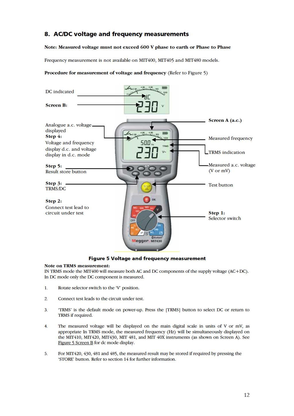
12
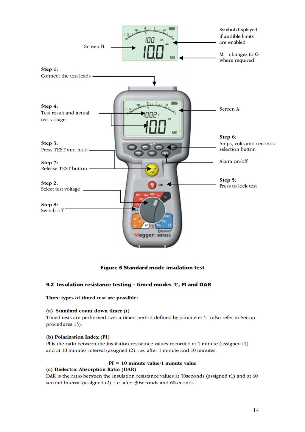
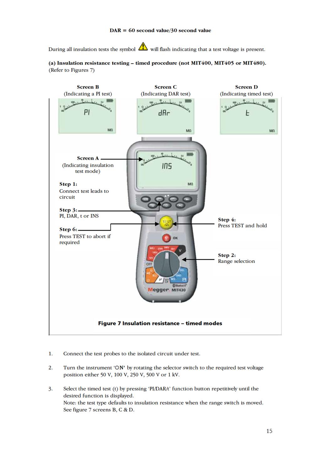
13 9. Insulation resistance testing - general Safety note: Insulation resistance testing is performed at high DC voltages and is hazardous if touched. Always observe the safety precautions when performing an insulation resistance test, and ensure all necessary health and safety precautions are observed. Automatic Discharge: Capacitive circuits are automatically discharged when the test button is released following an insulation test. The circuit under test must be completely de-energized and securely isolated before test connections are made. 9.1 Standard insulation resistance testing (Refer to Figure 6) Note: For MIT40X refer to section Connect the test probes to the isolated circuit under test. 2. Turn the instrument ON by rotating the selector switch to the desired test voltage (50 V, 100 V 250 V, 500 V or 1 kv). 3. Press and hold the [TEST] button to start the test. 4. The insulation resistance value, in both analogue and digital form is displayed together with the actual test voltage displayed on the secondary display (see Screen A of figure 6). 5. The insulation test can be locked on, by pressing the lock button [ ] whilst holding down the [TEST] button. To disable lock press the [TEST] button or lock [ ] button. 6. By pressing the [ua/v/s] button, the leakage current can be displayed (see Screen B). Not available on the MIT400 or MIT Release the [TEST] button before removing the test leads (to enable the instrument to discharge the circuit under test). If the display shows VOLTS, wait until it reaches zero. 8. On completion of testing, switch to the OFF position. Alternatively auto shut-off operates after 15 minutes of inactivity. 13
14
15
16
17 10. MIT40X testing The MIT40X has a selectable insulation test range from 10 V to 100 V in 1 V increments. The test voltage selected is the nominal test voltage. e.g. If 10 V is selected the actual voltage at the probe tip will be within the stated tolerance of ±1 V. The MIT40X is supplied with a default setting of 10 V. This can be adjusted in the setup procedure between 10 V and 100 V. To adjust the insulation test voltage refer to the Setup procedure. Testing is performed in exactly the same manner as a standard insulation test in section 9.1 above. 17
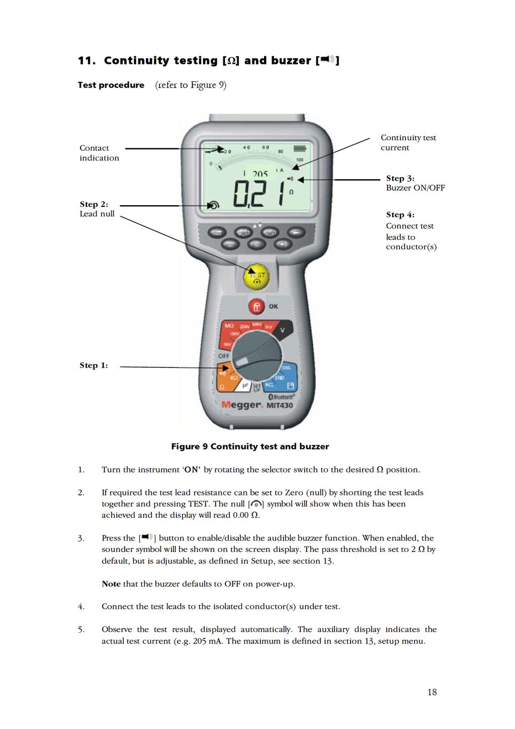
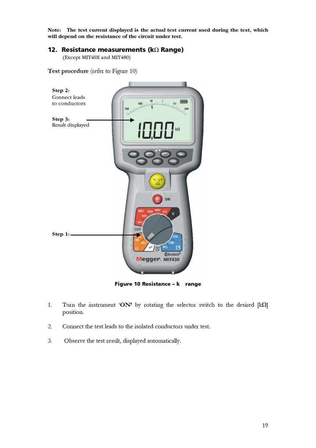
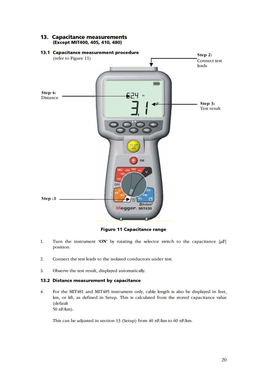
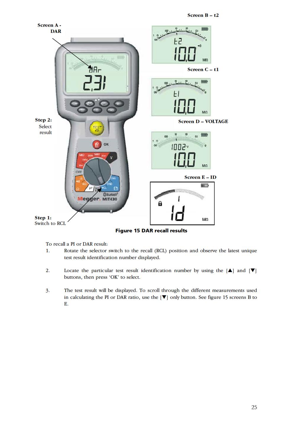
18
19
20
21 14. Setup options The setup position permits the user to adjust various threshold values and default settings. When SETUP is selected, the instrument firmware revision is displayed, followed by the buzzer alarm threshold. Displayed symbol BUZ Meaning Set top threshold for continuity buzzer in ohms. Buzzer sounds is result is less than set value. Default setting 2 Setting options 1, 2, 5, 10, 20 Instrument Loc Lock button ON/OFF ON ON / OFF All ISC InS t dis CAB Set v Setup maximum continuity short-circuit current. Sets low threshold for insulation test buzzer in Mohms. Buzzer sounds is result is more than set value. Timer for insulation test. Test will count down to 0 seconds. Test is active during countdown. Setup units for distance measurement Setup cable capacitance in nf (distance measurement) Setup insulation resistance voltage 200 ma 0.5 M 1 minute m 50 nf 10 V 20 ma, 200 ma (default 200 ma) 0,5, 1, 2, 5, 10, 20 M 1 to 10 minutes (in 1 minute increments m (meters), ft (feet) 40nF to 60nF 1nF increments 10V to 100V 1 volt increments All All MIT420 MIT40X MIT410 MIT481 All MIT481 MIT40X bt Bluetooth Paring setup - - MIT430 MIT485 21
22
23
24
25
26
27
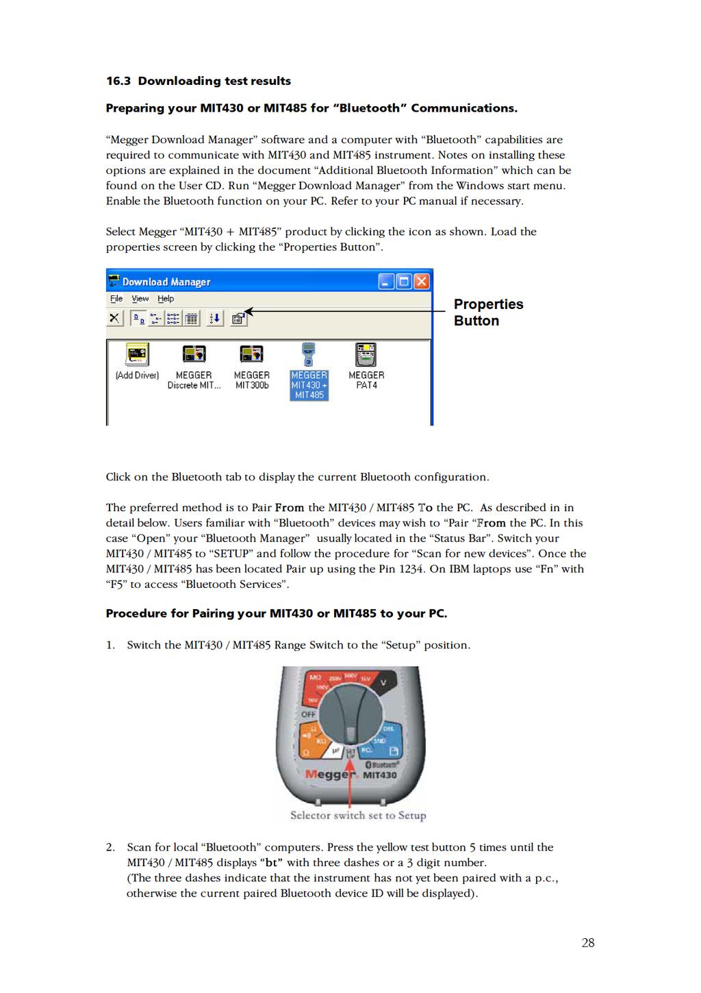
28
29
 If you get a message bubble or prompt asking you to accept a serial port connection then click")
30 6. A message bubble may also be displayed on the pc against the Bluetooth icon. 7. Click on this message and enter a Passkey of 1234 to accept the connection of the test instrument. (You may also need to accept other message prompts that may be displayed as part of this setup sequence) If you get a message bubble or prompt asking you to accept a serial port connection then click and accept, ticking the Always allow check box if available. 8. When complete the display will indicate End. 9. The MIT430 / MIT485 must now be switched to OFF after pairing to complete the process. 30
31 Standard Download Operation Having completed the initial installation and pairing, future downloads to the nominated PC becomes a very straightforward operation as described in the following simple steps. a) Run Megger Download Manager from the Windows start menu or short cut. b) Click once on the Megger MIT430 + MIT485 icon. c) Click on the download button. d) Switch the instrument to the SND position to initiate the communications port and start the download. (The download may take a few seconds to start if you have the Auto Detect serial port option set in Download Manager properties screen). Additional messages may appear to allow MIT to communicate. These should be accepted. e) After successful file transfer the MIT430 MIT485 will display End. f) The MIT430 / MIT485 should be switched to OFF. 31
32
33
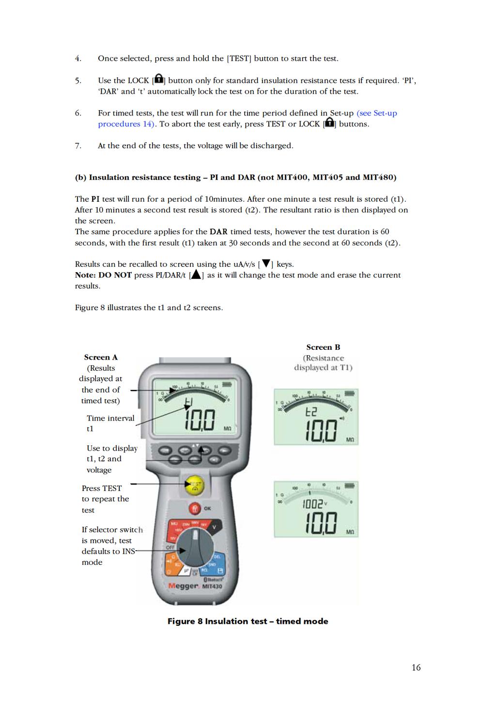
34 19. Specification All quoted accuracies are at +20 C. Insulation Nominal test voltages MIT400, V, 500 V, 1000 V MIT410, 420,43050 V, 100 V, 250 V, 500 V, 1000 V MIT V, 100 V MIT481, V, 100 V, 250 V, 500 V, 1000 V MIT40X 10 V to 100 V variable (1 V increments) Range full scale accuracy (Model dependant) All ranges ±2% ±2 digits up to 100 M. Then: 1000 volts ±3% ±2 digits ±0.2% per G 500 volts. ±3% ±2 digits ±0.4% per G 250 volts. ±3% ±2 digits ±0.8% per G 100 volts. ±3% ±2 digits ±2.0% per G 50 volts. ±3% ±2 digits ±4.0% per G Analogue range 1 G full scale Analogue range: 1 G full scale Short circuit current: 2 ma +0% -50% Terminal voltage: Test current on load: EN61557 operating range: -0% +20% ±1 V (Ii <1 ma) 1 ma at min. pass value of insulation specified in BS7671, HD384 and IEC364, EN , 2 ma max. 0,10 M to 1,00 G Leakage current range: 10 μa to 2000 μa Leakage current: Voltage display: Polarisation Index (PI): 10% ±3 digits 3% ±3 digits ±0.5% of rated voltage 10min / 1minute ratio Dielectric absorption Ratio (DAR): 60sec / 30sec ratio Notes: (1) All ranges measure from 0,00 M upwards. (2) Above specifications only apply when high quality silicone leads are being used. Continuity EN61557 operating range: Accuracy: Open circuit voltage: Test current: Zero offset at probe tips: 0,01 to 99,9 (0 to 100 on analogue scale) ± 2% ± 2 digits (0 to 100 ) 5 V ± 1 V 205 ma (±5 ma) (0.01 to 9.99 ) 20 ma (±1 ma) (10.0 to 99.9 ) 0,10 typical 34
35 Lead resistance zeroing: Buzzer: Resistance EN61557 operating range: Accuracy: Open circuit voltage: Short circuit current: Voltage range Default Voltmeter Up to 9,99 Variable limit 1, 2, 5, 10, 20 0,01 k to 1000 k (0 to 1 M on analogue scale) ±3% up to 50 k then ±5% ±2 digits 5 V ±1 V 1.5 ma ±0.2 ma 0 to 600 V d.c. ± 2% ± 2 digits 10 mv to 600 V TRMS sinusoidal ( Hz) ±2% ±2 digits 0 to 1000 V on analogue scale Unspecified input level 0 10 mv ( Hz) For non sinusoidal waveforms additional specifications apply: ±3% ±2 digits 101 mv 600 V TRMS and ±8% ±2 digits 10 mv 100 mv TRMS Operates at >25 volts a.c. or d.c., on any range except OFF Frequency: Hz (15Hz - 99,9Hz) ±0.5% ±1 digit (100Hz to 400Hz) Capacitance measurement MIT420, MIT430, MIT481 and MIT485. Measurement range: 100 pf to 10 μf Accuracy: ±5.0% ±2 digits Distance by capacitance: MIT420, MIT430,MIT481, MIT485 Arithmetic conversion from capacitance measurement Default capacitance distance measurement: 50 nf/km Capacitance range: 40 nf/km to 60 nf/km Result storage: Capacity: Download: Bluetooth class: Range: >1000 test results Bluetooth wireless Class II up to 10m Power supply: Battery life: Dimensions: Instrument Instrument + case Weight: Instrument only Instrument plus case 5 x 1,5V cells type IEC LR6 (AA, MN1500, HP7, AM3 R6HP) Alkaline NiMH rechargeable cells may be used insulation tests with duty cycle of 5 sec on 55 sec 1000 V into 1 M 220 x 92 x 50 mm (8.66in x 3.63in x 1.97in) 456 x 178 x 89mm (18in x 7in x 3.5in) 590gms, 775gms with boot (20.73oz (27.22oz)) 1.75kg (3.86lb) 35
36 Fuse: Use only a 500 ma (FF) 1000 V 32 x 6 mm ceramic fuse of high breaking capacity HBC 50 ka minimum. Glass fuses MUST NOT be fitted. Safety Protection The instruments meet IEC to 600 V phase to earth, Category IV. * Refer to safety warnings (see section 2). *MIT 405 IEC V phase to earth Category III Application IEC defines measurement categories from I to IV relating transient over voltages and the location within electrical installations. This instrument is designed for use at Category IV (Primary supply level) on 600 V phase to earth systems. E.M.C. In accordance with IEC Temperature effects Temperature coefficient <0,1% per C up to 1 G <0,1% per C per G above 1 G Environmental Operating range: -20ºC to +55 C Operating humidity: 95% RH at 0ºC to +35ºC, 70% RH +35ºC to +55ºC Storage temperature range: -30ºC to +80 C Calibration Temperature: +20 C Maximum altitude: 2000 m Dust and water protection: IP Basic and service errors The basic error is the maximum inaccuracy of the instrument under ideal conditions, whereas the service error is the maximum inaccuracy taking into effect of battery voltage, temperature, interference, system voltage and frequency, where applicable Basic error: See section Service error: Insulation range Continuity range Resistance range Voltage range Capacitance range Distance range Frequency range ±15% ±2 digits ±26% ±2 digits ±12% ±2 digits ±10% ±2 digits ±18% ±2 digits ±18% ±2 digits ±5% ±2 digits 36
37 21. Accessories Includes accessories 2 wire test lead set and crocodile clips SP5 Remote switch probe (not MIT400, 405, 40X, 480) Owner s information CD Calibration certificate Quick start guide Rubber boot Instrument case Additional in MIT430 and MIT485 Download Manager CD Optional accessories and replacements Fused 2 wire test lead set and crocodile clips Bluetooth Module qualifications details Bluetooth identifier: B02872 QPLN Reference: Q11406_WT12_SGS Contains Transmitter Module FCC ID: QOQWT12 The Bluetooth word mark and logo are owned by the Bluetooth SIG, Inc. and any use of such marks by Megger is under license. 37
38 22. Repair and Warranty The instrument contains static sensitive devices, and care must be taken in handling the printed circuit board. If an instrument s protection has been impaired it should not be used, but sent for repair by suitably trained and qualified personnel. The protection is likely to be impaired if for example; it shows visible damage; fails to perform the intended measurements; has been subjected to prolonged storage under unfavourable conditions, or has been subjected to severe transport stresses. NEW INSTRUMENTS ARE GUARANTEED FOR 3 YEARS FROM THE DATE OF PURCHASE BY THE USER. NOTE: Any unauthorized prior repair or adjustment will automatically invalidate the Warranty. CALIBRATION, REPAIR AND SPARE PARTS For service requirements for Megger instruments contact: Megger Limited or Megger Archcliffe Road Valley Forge Corporate Centre Dover 2621 Van Buren Avenue Kent CT17 9EN Norristown PA England U.S.A. Tel: +44 (0) Tel: Fax: +44 (0) Fax: Megger operate fully traceable calibration and repair facilities, ensuring your instrument continues to provide the high standard of performance and workmanship you expect. These facilities are complemented by a worldwide network of approved repair and calibration companies which offer excellent in-service care for your Megger products. Returning your product to Megger - UK and USA service centres 1. When an instrument requires recalibration, or in the event of a repair being necessary, a Returns Authorisation (RA) number must first be obtained from one of the addresses shown. You will be asked to provide the following information to enable the Service Department to prepare in advance for receipt of your instrument, and to provide the best possible service to you. Model, e.g. MIT400 Serial number, (e.g /1234) Reason for return, (e.g. calibration required, or repair) Details of the fault (if the instrument is to be repaired) 2. Make a note of the RA number. A returns label can be ed or faxed to you if you wish. 3. Pack the instrument carefully with plenty of padding, but no pressure on window or glass. 4. Ensure the returns label is attached, or that the RA number is clearly marked on the outside of the package and on any correspondence, before sending the instrument, carriage paid, to Megger. 5. You may track the progress of your return on line by accessing the Service/Support facilities at Approved Service Centres A list of Approved Service Centres may be obtained from the UK address shown. If outside UK/USA please consult your distributor for the most convenient Service Organisation. 38
39 M Megger Limited Archcliffe Road, Dover Kent CT17 9EN England T +44 (0) F +44 (0) E uksales@megger.com Megger 4271 Bronze Way, Dallas, Texas USA T (USA ONLY) T F E ussales@megger.com Megger Z.A. Du Buisson de la Couldre 23 rue Eugène Henaff TRAPPES France T +33 (0) F +33 (0) E infos@megger.com Megger Pty Limited Unit 26 9 Hudson Avenue Castle Hill Sydney NSW 2125 Australia T +61 (0) F +61 (0) E ausales@megger.com Megger Limited 110 Milner Avenue Unit 1 Scarborough Ontario M1S 3R2 Canada T (Canada only) T F E casales@megger.com Megger products are distributed in 146 countries worldwide. This instrument is manufactured in the United Kingdom. The company reserves the right to change the specification or design without prior notice. Megger is a registered trademark Part No. MIT400 _UG_en_V
MIT400 CAT IV Industrial Insulation Testers
 MIT400 CAT IV MIT400 CAT IV CAT IV 600 V applications TRMS & DC Voltage measurement Insulation testing up to 1000 V and 200 GΩ Continuity testing at 200 ma or 20 ma down to 0.01 Ω Pass/Fail limit alarms
MIT400 CAT IV Industrial Insulation Testers
 MIT400 CAT IV MIT400 CAT IV CAT IV 600 V applications TRMS & DC Voltage measurement Insulation testing up to 1000 V and 200 GΩ Continuity testing at 200 ma or 20 ma down to 0.01 Ω Pass/Fail limit alarms
MIT400 Series Insulation and continuity testers
 M MIT400 Series Insulation and continuity testers USER GUIDE USER GUIDE CONTENTS 1. Introduction... 3 2. Safety Warnings... 4 3. Symbols used on the instrument... 5 4. General Description... 6 4.1 Unpacking
MIT400 CAT IV Industrial Insulation Testers
 MIT400 CAT IV Industrial Insulation Testers MIT400 CAT IV Industrial Insulation Testers CAT IV 600 V applications Insulation testing up to 1000 V and 200 GΩ Continuity testing at 200 ma or 20 ma down to
G SAFETY WARNINGS. LT300 High current loop tester. User guide
 M LT300 High current loop tester User guide G SAFETY WARNINGS Safety Warnings and Precautions must be read and understood before the instrument is used. They must be observed during use. The earth loop
MIT400 CAT IV Industrial Insulation Testers
 MIT400 CAT IV MIT400 CAT IV n CAT IV 600 V applications n TRMS & DC Voltage measurement n Insulation testing up to 1000 V and 200 GΩ n Continuity testing at 200 ma or 20 ma down to 0.01 Ω n Pass/Fail limit
MIT400 Series CAT IV Insulation Resistance and Continuity Testers
 Insulation testing up to 1000 V and 200 GΩ Patented analog arc and dual digital display CAT IV 600 V rating TRMS & DC Voltage measurement Continuity testing at 200 ma or 20 ma down to 0.01 Pass/Fail limit
MIT400/2 CAT IV Insulation testers
 MIT400/2 CAT IV Insulation testers MIT400/2 CAT IV Insulation testers Designed for Electrical and Industrial testing Insulation testing up to 1000 V and 200 GΩ range Stabilised insulation test voltage
MIT415 Insulation tester
 MIT415 Insulation tester General features o 10V & 100V ESD testing o 25V, 50V, 250V & 500V additional ranges o Insulation testing up to 50Gohms (500V) o Continuity testing at 200mA or 20mA from 0.01ohms
MIT480/2 Insulation testers
 MIT480/2 Insulation testers MIT480/2 Insulation testers Insulation testing up to 500 V and 100 GΩ range in a hand held instrument 3 wire connection for A, B and E (Tip, Ring and Earth) connection (New)
MIT400/2 CAT IV Insulation testers
 MIT400/2 CAT IV Insulation testers MIT400/2 CAT IV Insulation testers Designed for Electrical and Industrial testing Insulation testing up to 1000 V and 200 GΩ range Stabilised insulation test voltage
MIT400/2. CAT IV Insulation testers MIT430/2: CAT IV Insulation testers
 MIT400/2 Designed for electrical and industrial testing Insulation testing up to 1000 V and 200 GΩ range Stabilized insulation test voltage (New) Single range, faster continuity testing from 0.01 Ω to
MEGGER BMM2000 Series Insulation Multimeters User Guide
 MEGGER BMM2000 Series Insulation Multimeters User Guide SAFETY WARNINGS Safety Warnings and Precautions must be read and understood before the instrument is used. They must be observed during use. The
TDR1000/3 TDR1000/3P CFL510G TDR500/3. Time Domain Reflectometers. User Manual. Page 1 of 1
 M TDR1000/3 TDR1000/3P CFL510G TDR500/3 Time Domain Reflectometers User Manual Page 1 of 1 CONTENTS Introduction...5 Overview...7 Instrument layout and display...7 Controls...9 Rotary switch...9 Range
BMM80 Premium Insulation Multimeters
 Insulation measurement to 200 GΩ 200 ma Short Circuit Current output mv Transducer inputs Test lead/transducer null facility Backlight Remote control switched probe included Capacitance Measurement to
MIT520/2 5kV Digital Insulation Tester USER MANUAL
 M MIT520/2 5kV Digital Insulation Tester USER MANUAL GSAFETY WARNINGS Safety Warning must be observed during use. The circuit under test must be switched off, de-energised, isolated and checked to be safe
VF3 AC Voltage detector. User Guide Guide de l utilisateur Bedienungsanleitung Guía del usuario
 VF3 AC Voltage detector User Guide Guide de l utilisateur Bedienungsanleitung Guía del usuario GSAFETY WARNINGS The VF3 Voltage detector may help in the indication of live AC circuits only, and must not
MIT510, MIT520 and MIT1020
 MIT510, MIT520 and MIT1020 Line supply or battery operated Digital/analog backlit display Measurement range to 15 TΩ (MIT510 and MIT520) and 35 TΩ (MIT1020) Automatic insulation resistance tests Automatic
Megger PO BOX 9007, Valley Forge PA USA T +1 (610) F +1 (610)
 F +1 (610)") M Megger Limited Archliffe Road, Dover Kent CT17 9EN England T +44 (0) 1304 502 101 F +44 (0) 1304 207 342 Megger PO BOX 9007, Valley Forge PA 19484-9007 USA T +1 (610) 676 8500 F +1 (610) 676 8610 Megger
M Megger Limited Archliffe Road, Dover Kent CT17 9EN England T +44 (0) 1304 502 101 F +44 (0) 1304 207 342 Megger PO BOX 9007, Valley Forge PA 19484-9007 USA T +1 (610) 676 8500 F +1 (610) 676 8610 Megger
IDEAL INDUSTRIES, INC. TECHNICAL MANUAL MODEL: MODEL: Multimeter Service Information
 IDEAL INDUSTRIES, INC. TECHNICAL MANUAL MODEL: 61-340 MODEL: 61-342 Multimeter Service Information The Service Information provides the following information: Precautions and safety information Specifications
5-kV and 10-kV Insulation Resistance Testers. n CAT IV 600 V safety rating. n Line supply or battery operated
 n CAT IV 600 V safety rating n Line supply or battery operated n Noise rejection (3mA or 4mA rms@200v and above) for use in high voltage substations or switchyards n 5mA output current provides fast charging
DM-45 Digital Multimeter
 INSTRUCTION MANUAL DM-45 Digital Multimeter Read and understand all of the instructions and safety information in this manual before operating or servicing this tool. Description The Greenlee DM-45 Digital
S1-552/2 5kV Digital Insulation Tester USER MANUAL
 M S1-552/2 5kV Digital Insulation Tester USER MANUAL GSAFETY WARNINGS Safety Warning must be observed during use. n The circuit under test must be switched off, de-energised, isolated and checked to be
DIGITAL DUAL DISPLAY AC/DC CLAMP METER MODEL-860A OPERATION MANUAL
 DIGITAL DUAL DISPLAY AC/DC CLAMP METER MODEL-860A OPERATION MANUAL DIGITAL DUAL DISPLAY AC/DC CLAMP METER MODEL-860A TABLE OF CONTENTS TITLE PAGE Safety Information Safety Symbols... 1 Meter Description...
MFT1800 Series. Multifunction testers. User Manual
 MFT1800 Series Multifunction testers User Manual Contents X.1 SAFETY WARNINGS... 4 1. Introduction... 5 2. Overview... 6 2.1 Front panel and controls 6 2.2 Waste electrical and electronic equipment 9 2.3
MFT1800 series. Multifunction testers. User manual
 M MFT1800 series Multifunction testers User manual 1 Contents X.1 SAFETY WARNINGS 4 1. Introduction 5 2. Overview 6 2.1 Front panel and controls 6 2.2 Waste electrical and electronic equipment 9 2.3 Battery
DVM645BI BENCH MULTIMETER TAFELMULTIMETER MULTIMETRE DE TABLE BANCO MULTÍMETRO TISCHMULTIMETER. User Manual. Gebruikershandleiding
 BENCH MULTIMETER TAFELMULTIMETER MULTIMETRE DE TABLE BANCO MULTÍMETRO TISCHMULTIMETER User Manual Gebruikershandleiding Manuel d'utilisation Gebrauchsanleitung Introduction BENCH MULTIMETER This manual
S1-1054/2 10kV Digital Insulation Tester USER MANUAL
 M S1-1054/2 10kV Digital Insulation Tester USER MANUAL GSAFETY WARNINGS Safety Warning must be observed during use. n The circuit under test must be switched off, de-energised, isolated and checked to
MIT510/2, MIT520/2 and MIT1020/2
 MIT510/2, MIT520/2 and MIT1020/2 Line supply or battery operated Digital/analog backlit display Measurement range to 15 TΩ (MIT510/2 and MIT520/2) and 35 TΩ (MIT1020/2) CAT IV 600 V safety rating Automatic
MIT515, MIT525, MIT1025
 MIT515, MIT525, MIT1025 5-kV and 10-kV Insulation Resistance Testers n Industry best guard terminal accuracy n Compact and lightweight for easy transport and use PI, DAR, DD, SV and ramp test Unique dual
USER'S MANUAL ACDC-100 TRMS ACDC-100. Versatile AC/DC Clamp-on Multimeter Series
 99 Washington Street Melrose, MA 02176 Fax 781-665-0780 TestEquipmentDepot.com USER'S MANUAL ACDC-100 TRMS ACDC-100 Versatile AC/DC Clamp-on Multimeter Series 1 1) SAFETY This manual contains information
IDEAL INDUSTRIES, INC. TECHNICAL MANUAL MODEL:
 IDEAL INDUSTRIES, INC. TECHNICAL MANUAL MODEL: 61-352 The Service Information provides the following information: Precautions and safety information Specifications Basic maintenance (cleaning, replacing
BM25 Automated 5-kV Insulation Tester
 Insulation resistance measured to >5 TΩ Automated testing Polarization Index and Step Voltage tests Dielectric discharge test for multilayer insulation RS-232 download capability Weatherproof DESCRIPTION
Keysight U1461A Insulation Multimeter/ U1453A Insulation Tester
 Keysight U46A Insulation Multimeter/ U453A Insulation Tester Quick Start Guide Standard Accessories Included In Your Purchase Standard Accessories Included In Your Purchase The following accessories are
15B+/17B+/18B+ Calibration Manual. Digital Multimeter
 5B+/7B+/8B+ Digital Multimeter Calibration Manual April 206 206 Fluke Corporation. All rights reserved. Specifications are subject to change without notice. All product names are trademarks of their respective
1507/1503. Insulation Testers. Users Manual
 1507/1503 Insulation Testers 1507/1503 Insulation Testers Introduction The Fluke model 1507 and model 1503 are battery-powered insulation testers (hereafter, "the Tester"). Although this manual describes
MS8268 HANDHELD DIGITAL MULTIMETER OPERATOR S INSTRUCTION MANUAL
 MS8268 HANDHELD DIGITAL MULTIMETER OPERATOR S INSTRUCTION MANUAL Table of Contents TITLE PAGE 1. GENERAL INSTRUCTIONS 1 1.1 Precaution safety measures 1 1.1.1 Preliminary 1 1.1.2 During use 2 1.1.3 Symbols
# Digital Multimeter
 #61-797 Digital Multimeter - 1 - TABLE OF CONTENTS 1.Introduction Precautions and Safety Information Symbols Safety 2.Specifications General Specifications Electrical Specifications Required Equipment
Agilent U1253B True RMS OLED Multimeter. Quick Start Guide
 Agilent U1253B True RMS OLED Multimeter Quick Start Guide The following items are included with your multimeter: Silicone test leads 4 mm probes Alligator clips Printed Quick Start Guide Rechargeable 8.4
Dawson DDM230C. True RMS Multimeter with Bar Graph Display User s Manual
 Dawson DDM230C True RMS Multimeter with Bar Graph Display User s Manual Table of Contents LIMITED WARRANTY AND LIMITATION OF LIABILITY... 3 Out of the Box... 3 Accessories... 4 Safety Information... 4
MFT1700 series. Multifunction testers. User manual
 M MFT1700 series Multifunction testers User manual 1 Contents SAFETY WARNINGS...3 1. Introduction...4 2. Overview...4 2.1 Front panel and controls...6 2.2 Waste electrical and electronic equipment...6
MM700. INSTRUCTION MANUAL Auto-Ranging Digital Multimeter True RMS
 INSTRUCTION MANUAL Auto-Ranging Digital Multimeter True RMS Measurement Technology MM700 DATA & RANGE HOLD LOW IMPEDANCE AUDIBLE CONTINUITY MIN / MAX / RELATIVE TEMPERATURE DIODE TEST CAPACITANCE & FREQUENCY
SUBJECT TO CHANGE WITHOUT NOTICE
 www.sifamtinsley.co.uk DATASHEET Multifunction Meters Transducers & Isolators Temperature Controllers Converters & Recorders Digital Panel Meters ijunior / JUNIOR Current Transformers Analogue Panel Meters
AC/DC CLAMP METER USER S MANUAL
 AC/DC CLAMP METER USER S MANUAL CONTENTS PAGE SAFETY INFORMATION SYMBOL EXPLANATION SAFETY PRECAUTIONS 1 1 2 MAINTENANCE 3 GENERAL DESCRIPTION 4 PANEL DESCRIPTION 4 OPERATING INSTRUCTIONS... 7 SPECIFICATIONS
Digital Clamp Meter Model: &
 Digital Clamp Meter Model: 72-7224 & 72-7226 1 SAFETY INFORMATION Please read these instructions carefully before use and retain for future reference. This meter is designed to meet IEC61010-1, 61010-2-032,
MM700. True RMS ENGLISH. INSTRUCTION MANUAL Auto-Ranging. Measurement Technology
 INSTRUCTION MANUAL Auto-Ranging Digital Multimeter er True RMS Measurement Technology MM700 DATA & RANGE HOLD LOW IMPEDANCE AUDIBLE CONTINUITY MIN / MAX / RELATIVE TEMPERATURE DIODE TEST CAPACITANCE &
79/26 Series III Multimeter
 79/26 Series III Multimeter Instruction Sheet W Read First: Safety Information Never use the meter if the meter or test leads look damaged. Be sure the test leads and switch are in the correct position
CM605. User Manual AC/DC LOW CURRENT CLAMP-ON METER ENGLISH
 AC/DC LOW CURRENT CLAMP-ON METER CM605 ENGLISH User Manual Statement of Compliance Chauvin Arnoux, Inc. d.b.a. AEMC Instruments certifies that this instrument has been calibrated using standards and instruments
Analog Technologies. Multimeter 15B and17b
 Figure 1. The Photo of Actual 17B Figure 2. The Photo of Actual 15B FEATURES Maximum Voltage between Any Terminal and Earth Ground: 1000V Temperature Coefficient: 0.1 (specified accuracy)/ (28
Advanced Test Equipment Rentals ATEC (2832)
") Established 1981 Advanced Test Equipment Rentals www.atecorp.com 800-404-ATEC (2832) MIT515, MIT525, MIT1025 MIT515, MIT525, MIT1025 5-kV and 10-kV Insulation Resistance Testers n Industry best guard terminal
Established 1981 Advanced Test Equipment Rentals www.atecorp.com 800-404-ATEC (2832) MIT515, MIT525, MIT1025 MIT515, MIT525, MIT1025 5-kV and 10-kV Insulation Resistance Testers n Industry best guard terminal
Model ST Instruction Manual. True RMS Autoranging Digital Multimeter. reedinstruments. www. com
 Model ST-9933 True RMS Autoranging Digital Multimeter Instruction Manual reedinstruments com Table of Contents Safety... 3 Features... 4 Specifications...4-8 Technical...4-5 Accuracy...5-8 Display Description...
ICM 136R Operating Instruction Electrical Clamp-Multimeter
 ICM 136R Operating Instruction Electrical Clamp-Multimeter Safety Information For safe operation of this clamp-multimeter, read these instructions completely before you use it and comply with them fully.
Dawson DDM190. Digital Multimeter User s Manual
 Dawson DDM190 Digital Multimeter User s Manual TABLE OF CONTENTS LIMITED WARRANTY AND LIMITATION OF LIABILITY... 3 Out of the Box... 3 Accessories.. Error! Bookmark not defined. Safety Information... 7
CL900. True RMS 1000V 2000A 60MΩ ENGLISH. INSTRUCTION MANUAL 2000A Digital Clamp Meter. Measurement Technology
 ENGLISH INSTRUCTION MANUAL 2000A Digital Clamp Meter True RMS Measurement Technology NON-CONTACT VOLTAGE TESTING INRUSH CURRENT LOW IMPEDANCE DATA HOLD RANGE HOLD AUDIBLE CONTINUITY DIODE TEST CAPACITANCE
DDM350 Pen-Type Digital Multimeter User s Manual
 DDM350 Pen-Type Digital Multimeter User s Manual CONTENTS LIMITED WARRANTY AND LIMITATION OF LIABILITY....1 Out of the Box...1 Accessories......2 Safety Information...2 Safety Symbols...3 Certification......4
USER MANUAL 600A AC Clamp Meter + NCV Model MA610
 USER MANUAL 600A AC Clamp Meter + NCV Model MA610 Additional User Manual Translations available at www.extech.com Introduction Thank you for selecting the Extech MA610 Clamp Meter. This meter measures
MM V 10A ENGLISH. INSTRUCTION MANUAL Auto-Ranging DATA HOLD AUDIBLE CONTINUITY MIN / MAX TEMPERATURE DIODE TEST CAPACITANCE
 INSTRUCTION MANUAL Auto-Ranging Digital Multimeter MM400 DATA HOLD AUDIBLE CONTINUITY MIN / MAX TEMPERATURE DIODE TEST CAPACITANCE 600V 10A 40MΩ 2 GENERAL SPECIFICATIONS Klein Tools MM400 is an auto-ranging
Insulation Testers and Earth Ground Testers
 Insulation Testers and Earth Ground Testers With a 5000 V MegOhmMeter for industrial-strength insulation testing and a range of compact hand-held instruments, we offer a solution for every troubleshooting
ODEN AT Primary Current Injection Test System
 ODEN AT Most Advanced Primary Current Injection Test System to simplify all types of switchgear and CT commissioning, ground grid, circuit breaker testing and more Modular design to permit optimal user
GammaPAT MI 3311 Short instructions Ver. 1.4, Code no
 GammaPAT MI 3311 Short instructions Ver. 1.4, Code no. 20 751 626 Distributor: Manufacturer: METREL d.d. Ljubljanska cesta 77 1354 Horjul Slovenia E-mail: metrel@metrel.si http://www.metrel.si 2010 METREL
EM420A/420B DIGITAL MULTIMETER OWNERS MANUAL Read this owners manual thoroughly before use
 http://www.all-sun.com EM420A/420B DIGITAL MULTIMETER OWNERS MANUAL V Read this owners manual thoroughly before use WARRANTY This instrument is warranted to be free from defects in material and workmanship
TRMS LEAKAGE CURRENT CLAMP-ON METER 565
 TRMS LEAKAGE CURRENT CLAMP-ON METER 565 E N G L I S H User Manual Statement of Compliance Chauvin Arnoux, Inc. d.b.a. AEMC Instruments certifies that this instrument has been calibrated using standards
Model UT511 OPERATING MANUAL
 Model UT511 OPERATING MANUAL TITLE PAGE Introduction Unpacking the Meter Safety Information International Electrical Symbols Battery Saver (Sleep Mode) Battery Indication The Meter Structure Display Key
True RMS Digital Multimeter Model:
 True RMS Digital Multimeter Model: 72-7780 1 SAFETY INFORMATION Please read these instructions carefully before use and retain for future reference. This meter is designed to meet IEC61010-1, 61010-2-032,
Agilent U1251B and U1252B Handheld Digital Multimeter. Quick Start Guide
 Agilent U1251B and U1252B Handheld Digital Multimeter Quick Start Guide The following items are included with your multimeter: Silicone test leads 4 mm probes Alligator clips Printed Quick Start Guide
USER'S MANUAL. ACD-6 Pro. ACD-6 TRMS Pro. Versatile Clamp-on Multimeter Series
 USER'S MANUAL ACD-6 Pro ACD-6 TRMS Pro Versatile Clamp-on Multimeter Series 1 1) SAFETY This manual contains information and warnings that must be followed for operating the instrument safely and maintaining
Instruction Manual ICM 135R Electrical Clamp Multimeter EN FR IT DE ES
 Instruction Manual ICM 135R Electrical Clamp Multimeter EN FR IT DE ES Safety Information For safe operation of this clamp-multimeter, read these instructions completely before you use it and comply with
EX350 Series USER GUIDE. True RMS Digital Multimeters. EX350 True RMS Digital Multimeter EX355 True RMS Digital Multimeter with Temperature
 USER GUIDE True RMS Digital Multimeters EX350 Series EX350 True RMS Digital Multimeter EX355 True RMS Digital Multimeter with Temperature Table of Contents 1. INTRODUCTION 3 2. SAFETY INFORMATION 4 3.
USER'S MANUAL DMR-6700
 USER'S MANUAL Multimeter True RMS DMR-6700 CIRCUIT-TEST ELECTRONICS www.circuittest.com Introduction This meter measures AC/DC Voltage, AC/DC Current, Resistance, Capacitance, Frequency (electrical & electronic),
600A Clamp Meters w/tightsight Display
 V 750V #61-764 #61-766 #61-768 600A Clamp Meters w/tightsight Display Instruction Manual 99 Washington Street Melrose, MA 02176 Fax 781-665-0780 TestEquipmentDepot.com CAT.IV 600V CAT.III 1000V 600A 61-766
99 Washington Street Melrose, MA Fax TestEquipmentDepot.com # # AAC Clamp Meter. Instruction Manual
 99 Washington Street Melrose, MA 02176 Fax 781-665-0780 TestEquipmentDepot.com #61-732 #61-736 400 AAC Clamp Meter Instruction Manual AC HOLD APO DC KMΩ mva WARNING Read First: Safety Information Understand
Multi-Function Installation Tester MEGGER CM500. User Guide MEGGER
 Multi-Function Installation Tester MEGGER CM500 User Guide MEGGER Contents Safety Warnings 3 Initial Setup 4 General Description 6 Features, Controls and Connections 8 Operation 10 Backlight 10 Auto shut-off
MEGGER CM300 MK II, CM400 MK II & CM500
 MEGGER CM300 MK II, CM400 MK II & CM500 Multi-Function Installation Testers User Guide MEGGER Contents Safety Warnings 3 Initial Setup 4 General Description 6 Features, Controls and Connections 8 Operation
MS8216 DIGITAL MULTIMETER OPERATOR S MANUAL
 MS8216 DIGITAL MULTIMETER OPERATOR S MANUAL CONTENTS 1. SAFETY INFORMATION 1 1.1 PRELIMINARY 1 1.2 DURING USE 2 1.3 SYMBOLS 4 1.4 MAINTENANCE 4 2. DESCRIPTION 5 2.1 NAMES OF COMPONENTS 5 2.2 FUNCTION AND
GAMMA 12 DIGITAL MULTIMETER
 Gamma 12 www.sifamtinsley.co.uk DATASHEET Issue 1.0 Multifunction Meters Transducers & Isolators Temperature Controllers Converters & Recorders Digital Panel Meters Current Transformers Analogue Panel
INSTRUCTION MANUAL ACD-10 PRO & TRMS PRO
 INSTRUCTION MANUAL ACD-10 PRO & TRMS PRO AMPROBE 1 Congratulations! You are now the owner of an AMPROBE Instrument. It has been quality crafted according to quality standards and contains quality components
Analog Digital Multimeter with Insulation Resistance Measurement
 RISH MIT 30 Product Features: RISH MIT 30 is Analog Digital Multimeter with insulation resistance measurement, which measures VAC, VDC, VAC+DC,Frequency, ma DC, ma AC+DC,Resistance, continuity, Diode,
IDM 503 & 505 Digital Multimeters
 Instruction Manual IDM 503 & 505 Digital Multimeters IDM 505 SECTION 1 SAFETY INFORMATION Safety Information Understand and follow operating instructions carefully. Use the Instrument only as specified
ETHOS 5030 TRUE-RMS DIGITAL MULTIMETER OPERATION MANUAL
 ETHOS 5030 TRUE-RMS DIGITAL MULTIMETER OPERATION MANUAL 1 1. SAFETY INFORMATION SAFETY SYMBOLS Warning! Dangerous Voltage (Risk of electric shock). Caution! Refer to the user s manual before using this
MW3105 DIGITAL CLAMP MULTIMETER
 MW3105 DIGITAL CLAMP MULTIMETER 2 M MW3105 A 01 INTRODUCTION 1.1 - Unpacking and inspection Upon removing your new Digital Clamp Meter from its packing, you should have the following items: 1. Digital
Portable Appliance Testers. OmegaPAT MI 2140 BetaPAT MI 2141 User Manual Ver Code No
 Portable Appliance Testers OmegaPAT MI 2140 BetaPAT MI 2141 User Manual Ver. 1.2. Code No. 20 750 684 Distributor: Producer: METREL d.d. Ljubljanska 77 SI-1354 Horjul E-mail: metrel@metrel.si http://www.metrel.si
MS2109A AC/DC Clamp Meter. User Manual. Contents
 MS2109A AC/DC Clamp Meter User Manual Contents 1. Safety information 1 1.1 Preparation 1 1.2 Usage 1 1.3 Signs and Labels 2 1.4 Maintenance 2 2. Description 2 2.1 Part name 3 2.2 Switch and button description
RISH MIT 30 Analog Digital Multimeter with Insulation Resistance Measurement
 RISH MIT 30 Analog Digital Multimeter with Insulation Resistance Measurement Data Sheet Analog Digital Multimeter with Insulation resistance www.rishabh.co.in Page 1 of 6 Version: J 28/12/2011 Application
Thank you again for choosing AstroAI, if you have any questions or concerns regarding your product, please contact us at
 ASTROAI USER MANUAL DT132A 4000 Count Auto-Ranging Multimeter Thank you for purchasing the AstroAI DT132A 4000 Count Auto-Ranging Multimeter. It is a 3 ¾ digit, 3999 counts, auto-ranging digital multimeter.
MS2030 CAT III 600 V A V AUTO RS232
 MS2030 AC Digital Clamp Meter User s Manual CAT III 600 V AUTO RS232 A V CONTENTS 1.Introduction...1 2.Safety Information...1 2.1 Precautions...1 2.2 Safety Symbols...3 3. Description...4 3.1 Front Panel...4
ProfiScale MULTI Multimeter
 1,5 V 9V 200 mv 600 V 200 ma 1/10 A ProfiScale MULTI Multimeter en Operating instructions BURG-WÄCHTER KG Altenhofer Weg 15 58300 Wetter Germany Introduction Want the reassurance of knowing whether current
15B & 17B. Users Manual. Multimeters
 15B & 17B Multimeters Users Manual PN 1991246 October 2002 Rev. 3, 3/04 2002-2004 Fluke Corporation. All rights reserved. Printed in China. All product names are trademarks of their respective companies.
312, 316, 318. Clamp Meter. Users Manual
 312, 316, 318 Clamp Meter Users Manual PN 1989445 July 2002 Rev.2, 2/06 2002, 2006 Fluke Corporation. All rights reserved. Printed in China. All product names are trademarks of their respective companies.
IDEAL INDUSTRIES, INC. TECHNICAL MANUAL MODEL:
 IDEAL INDUSTRIES, INC. TECHNICAL MANUAL MODEL: 61-920 The Service Information provides the following information: Precautions and safety information Specifications Performance test procedure Calibration
MS8250A/B OPERATION MANUAL MS8250A. Hz% FUNC REL RANGE REL HOLD OFF 10A. Hz% A NCV. Hz% COM. A ma 10A FUSED 600V CAT IV.
 MS8250A/B DIGITAL MULTIMETER OPERATION MANUAL AUTO DC AC REL hfe PCLINK % C F kmωkz nµmfav MS8250A DIGITAL MULTIMETER Auto Power Off RANGE REL HOLD FUNC NCV A ma OFF 10A A ma 10A FUSED 600V CAT IV COM
AC/DC DIGITAL CLAMP METER OPERATION MANUAL
 AC/DC DIGITAL CLAMP METER OPERATION MANUAL HYS005661 A0 ACCESSORIES 6. ACCESSORIES 1) Test Leads: Electric Ratings 1000V 10A 1 pair (set) 2) Operating Manual 1 copy 3) 1.5V AAA Battery 3 piece - - 55 -
BENNING. Service Information MODEL: MM1-1 / MM1-2 / MM1-3
 BENNING MODEL: MM1-1 / MM1-2 / MM1-3 Service Information The Service Information provides the following information: Precautions and safety information Specifications Basic maintenance (cleaning, replacing
GAMMA 10 DIGITAL MULTIMETER
 Gamma 10 www.sifamtinsley.co.uk DATASHEET Issue 1.0 Multifunction Meters Transducers & Isolators Temperature Controllers Converters & Recorders Digital Panel Meters Current Transformers Analogue Panel
SMART TWEEZERS Model ST-1 User s Manual Version 1.0
 SMART TWEEZERS Model ST-1 User s Manual Version 1.0 Patent Pending TABLE OF CONTENTS Notice The contents of this document is believed to be accurate, but is not guaranteed by Excelta Corporation. The information
Technical Data Sheet. Zeta 20
 Technical Data Sheet Zeta 20 Application Zeta 20 is the digital Insulation and continuity Tester is suitable for following Measurement of the insulation resistance on electrically dead equipment and systems
Instruction Manual IDM 98-III & IDM 99-III Digital Multimeters
 Africa 1 & 2 Indianapolis Street Kyalami Business Park Kyalami, Midrand, South Africa Asia 460 Alexandra Road, #15-01A PSA Building Singapore 119963 Instruction Manual IDM 98-III & IDM 99-III Digital Multimeters
KMD-S04 Multímetro de bolsillo
 www.grupotemper.com KMD-S04 Multímetro de bolsillo Table of Contents Title Page Overview ~~~~~~~~~~~~~~~~~~~~~~~~~~~~~~~~~~~~~~~~~~ 3 Unpacking Inspection ~~~~~~~~~~~~~~~~~~~~~~~~~~~~~~~~~ 4 Safety Information
Instruction Manual IDM 66RT Digital Multimeter
 Instruction Manual IDM 66RT Digital Multimeter EN Warning...................................... Safety sheet.............................................. Read First Safety Information Understand and follow
Agilent U1273A/U1273AX Handheld Digital Multimeter. Quick Start Guide
 Agilent U1273A/U1273AX Handheld Digital Multimeter Quick Start Guide Verify that you received the following items in the shipment of your multimeter: One pair of red and black test leads One pair of 4
AC/DC Current Probes Model MR411 Model MR521
 AC/DC Current Probes Model MR411 Model MR521 USER MANUAL OL OL ON ON 600V CAT III - 600A 600V CAT III - 1500A 60A 600A OFF 150A 1500A OFF! OUTPUT: 600A: 1 mv/a 60A: 10 mv/a! OUTPUT: 1500A: 1 mv/a 150A: