IRPLMB1E International Rectifier 233 Kansas Street, El Segundo, CA USA
|
|
|
- Britton Chapman
- 6 years ago
- Views:
Transcription

 are becoming very common in Europe to drive a wide range of lamps with power between 18W and 26W like PLC 18W, PLT 18W, TC-L 18W, TC-L")
1 Topics Covered IRPLMB1E International Rectifier 233 Kansas Street, El Segundo, CA USA IRPLMB1E - 25W 230VAC small size ballast using IR2520D By Cecilia Contenti Overview Features Electrical Characteristics IR2520D Ballast Control IC Circuit Description Miniballast Circuit Diagram Functional Description Fault Conditions Miniballast Layout Design Tip: AUto-restart Option Design Procedure to adapt the design to different lamp types 1. Overview Small sizes ballasts (often called Matchbox ballasts) are becoming very common in Europe to drive a wide range of lamps with power between 18W and 26W like PLC 18W, PLT 18W, TC-L 18W, TC-L 24W, TC-F 18W, TC-F 24W, TC-DEL/TEL 26W, T5 24W, T8 18W, T5C 22W and TR 22W. Limiting the maximum power to 25W the design does not need to conform to THD and PF requirements and this allows saving the PFC stage reducing the components count and maintaining a very small size. The MINIBALLAST1 is an electronic ballast for driving 26W compact fluorescent lamps from 220VAC. The circuit provides all of the necessary functions for preheat, ignition and on-state operation of the lamp and also includes the EMI filter and the rectification stage. The ballast size is 36mmx55mm. The circuit is built around the IR2520D Ballast Control IC. The IR2520D provides adjustable preheat time, adjustable run frequency to set the lamp power, high starting frequency for soft start and to avoid lamp flash, fault protection for open filament condition and failure to strike, low AC line protection and auto-restart after line brownout conditions. The IR2520D is a low-cost solution with only 8 pins and allows the component count for the complete solution to be reduced down to 19 components. 1
2 2. Features! Programmable run frequency! Programmable preheat time! Open filaments and no-lamp protection! Failure to Strike and deactivated-lamp protection! Low AC line protection 3. Electrical Characteristics Input Power: 220VAC Input Current: 220VAC Starting Frequency: 100KHz Average Run Frequency: 40KHz Ballast turn-on voltage: 120VAC Ballast turn-off voltage: 70VAC Input (VAC) Pin (W) Iinrms (ma) Vbusav (V) Freq. (KHz) PF THD (%) IR2520D Ballast Control IC The IR2520D is intended for driving CFL and TL lamps in CFL or matchbox (small size ballasts) applications. The IR2520D integrates all of the necessary functions for preheat, ignition and on-state operation of the lamp, plus, lamp fault protection and low AC-line protection, together with a complete high and low-side 600V half-bridge driver. The IR2520D has only 8 pins and fits into a standard SOIC8 or DIP8 package. The IR2520D has been designed to overcome the disadvantage of discrete selfoscillating solutions while maintaining low cost. In the CFL market, the self-oscillating bipolar transistor solution is still more popular than a ballast control IC plus FETs solution due to lower cost. This approach is very simple in nature but has disadvantages including:! DIAC or additional circuit required for starting, additional free-wheeling diodes required! operating frequencies determined by bi-polar transistor storage time and toroid saturation (not easy to design, very dependent on tolerances in production and difficult to set the frequencies precisely),! unreliable always hot PTC thermistor used for preheat that often fails in the field,! no protection against lamp non-strike or open filaments conditions,! no smooth frequency ramping during ignition,! capacitive mode operations,! high crest factor in the lamp current. These can result in high susceptibility to components and load tolerances and/or catastrophic failure of ballast output stage components and a short lamp life. The IR2520D includes adaptive zero-voltage switching (ZV, adaptive run frequency for zero-voltage switching), internal crest factor and non-zero voltage switching (ZVS) protection, as well as an integrated bootstrap diode. The heart of this IC is a voltage controlled oscillator (VCO) with externally programmable minimum frequency and a 0-5VDC analog voltage input. One of the biggest advantages of the IR2520 is that it uses the VS pin and the RDSon of the low-side half-bridge MOSFET for over-current protection and to detect non-zvs conditions. An internal 600V FET connects the VS pin to the VS sensing circuitry and allows for the VS pin to be accurately measured during the time when pin LO is high, while withstanding the high DC bus voltage during the other portion of the switching cycle when the high-side FET is turned on and VS is at the DC bus potential. This eliminates the need for a highprecision current sensing resistor that is typically used to detect over current. Please refer to the IR2520D datasheet for further information on the IR2520D including electrical parameters, state diagram and complete functional description. As a result of the IR2520 features, the MINIBALLAST1 circuit using the IR2520D is a complete matchbox solution that offers better reliability and longer lamp life than self oscillating solutions while reducing component count and ballast size. 2
3 5. Circuit Description The schematic for MINIBALLAST1 is shown in figure 5.1. The BOM with the components values is shown in table 5.2. The ballast incorporates a fuse, EMI filter, input rectifier, bus capacitor, half-bridge, control and output stage. The output stage is the classical resonant circuit consisting of an inductor, LRES, and a capacitor, CRES. The circuit is built around the IR2520D Ballast Control IC. The IR2520 provides adjustable preheat time, adjustable run frequency to set the lamp power, high starting frequency (about 2.5 times fmin) to avoid lamp flash, capacitive mode protection for open filament condition and current crest factor protection for failure to strike or no lamp conditions. The AC line input voltage is rectified to provide a bus voltage of approximately 300 volts. The start up resistor, Rsupply (in the reference design we have 2 resistors, Rsupply and Rsupply 2 in series), is sized such that they can supply the micro-power current during under-voltage lockout (UVLO). When VCC exceeds the UVLO+ threshold, the IR2520 begins to oscillate and the charge pump circuit (CSNUB, DCP1 and DCP2) supplies the current to VCC that causes the internal 15.6V zener clamp to regulate. The IR2520 Ballast Control IC controls the frequency of the half-bridge programming the right parameters on the lamp to provide lamp preheat, lamp ignition, running mode, low AC line protection and lamp/ ballast fault protection. RSUPPLY DCP2 F1 LF CF BR1 CBUS VCC 1 CVCC COM 2 FMIN 3 RFMIN VCO 4 IR2520 VB 8 HO 7 VS 6 LO 5 MHS CBS LRES CSNUB LAMP CRES CVCO MLS CDC DCP1 Fig. 5.1) MINIBALLAST1 Circuit Diagram 3
4 Item # Qty Manufacturer Part Number Description Reference 1 1 International Rectifier DF10S Bridge Rectifier, 1A 1000V BR1 2 1 Dale CW-1/2 Resistor, 0.5Ohm, 1/.2W F Panasonic Digikey ECQ-U2A104ML P10730-ND Capacitor, 0.1uF 275 VAC Epcos B82145-A1105-J EMI Inductor, 1mH 370mA Digikey M5830-ND RF Chockes 1mH 200mA 5 1 Wima MKS2 Series Capacitor, 47nF 400V CDC 6 1 Panasonic EEU-EB2V100 Capacitor, 10uF 350VDC 105C CBUS 7 1 Panasonic ECJ-3VB1H104K Capacitor, 0.1uF 50V 1206 CBS 8 1 Panasonic ECJ-3VF1E474Z Capacitor, 0.47uF 25V 1206 CVCO 9 1 Panasonic ECY-3YB1E105K Capacitor, 1uF 25V 1206 CVCC 10 1 AVX 1812AA681J Capacitor, 680pF 1KV SMT 1812 CSNUB 11 1 Wima MKP4 Series Capacitor, 4.7nF 1KV Polypropylene CRES 12 1 International Rectifier IR2520D IC, Ballast Driver IC BALLAST 13 1 VOGT Inductor, 2.25mH, 5%, 1Apk LRES 14 2 International Rectifier IRFU320 Transistor, MOSFET MHS, MLS 15 2 Panasonic Resistor, 1M, 1206, 100V RSUPPLY1, RSUPPLY Panasonic ERJ-8ENF6812V Resistor, 68.1K, 1%, 1206 RFMIN 17 2 Diodes LL4148DICT-ND Diode, 1N4148 SMT DL35 DCP1, DCP WAGO Connector, 2 terminal X WAGO Connector, 4 terminal X2 Total 22 TABLE 5.2) MINIBALLAST1 Bill Of Materials. Lamp type: Spiral CFL 26W, Line Input Voltage: VAC. Note: Different lamp types may require BOM changes. CF LF 4
. This minimizes voltage spikes and lamp flash at startup.")

5 6. Functional Description Figure 6.1 shows the voltage across the lamp and the current in the resonant inductor LRES during Startup, Preheat, Ignition and Run Mode. At startup, VCO is 0V and the frequency is very high (about 2.5 times fmin). This minimizes voltage spikes and lamp flash at startup. The frequency ramps down towards the resonant frequency of the high-q ballast output stage, causing the lamp voltage and lamp current to increase. During this time, the filaments of the lamp are pre-heated to the emission temperature to guarantee a long lamp life. The frequency keeps decreasing until the lamp ignites. If the lamp ignites successfully, the IR2520D enters RUN Mode. If the minimum frequency has been chosen below or very close to the resonant frequency, the IC will work near resonance and will adjust the frequency continuously to maintain ZVS at the half-bridge and to minimize the losses in the FETs. If the minimum frequency has been chosen higher than the resonant frequency the IR2520D will work at the minimum frequency. Figure 6.2 shows the current across the resonant inductor and the voltage across the lamp filaments at the startup. Fig. 6.1: Voltage across the lamp (yellow waveform) and current in the resonant inductor (green waveform) during Startup, Preheat, Ignition and Run Mode When power is turned on, the IR2520D goes into Under Voltage Lockout (UVLO) mode. The UVLO mode is designed to maintain a very low (<200uA) supply current and to guarantee that the IC is fully functional before the high- and low-side output drivers are activated. During UVLO, the high- and low-side driver outputs (LO and HO) are both low and pin VCO is pulled down to COM for resetting the starting frequency to the maximum. Once VCC reaches the startup threshold (UVLO+), the IR2520D turns on and the half-bridge FETs start to oscillate. The IC goes into Frequency Sweep Mode. Figure 6.2: Voltage across the lamp filaments (yellow) and current in the resonant inductor (green) at the startup. 5

6 Figure 6.3 shows the VS (HB) Voltage, the lamp voltage and the lamp current during Run Mode. Figure 6.3: VS (HB) Voltage (blue), Lamp Voltage (yellow) and the Lamp Current (green) during Run Mode. 7. Fault Conditions In case of fault conditions such as open filaments, failure to strike, deactivated lamp or no lamp, the IR2520D will go into Fault Mode. In this mode the oscillator is latched off. To reset the IC back to preheat mode, VCC must be recycled below and above the UVLO thresholds. Resetting the mains does this. In case of low AC line, the IR2520D will automatically increase the frequency to maintain ZVS. In this way, the ballast will work at a lower power during a low AC line condition and will operate at the proper power again when the line increases again Failure To Strike/ Deactivated Lamp Protection This protection relies on the crest factor protection together with the non-zvs circuit of the IR2520D, both enabled when the voltage in pin VCO reaches 4.6V. In order to detect failure to strike conditions, the IR2520D performs an internal crest factor measurement for detecting excessive dangerous currents or inductor saturation that can occur during a lamp nonstrike fault condition or deactivated lamp condition. The IR2520D measures the VS pin during the entire on-time of the low-side MOSFET. Should the peak current exceed the average current by a factor of 4 during the on-time of LO, the IC will enter Fault Mode and both gate driver outputs will be latched low. Performing the crest factor measurement provides a relative current measurement that cancels temperature and/or tolerance variations of the RDSon of the low-side half-bridge MOSFET and does not need to be programmed differently for different lamp types. During normal operation, the current will increase until the lamp ignites. After lamp ignition the current will decrease down to the nominal current. Should a lamp non-strike condition occur where the filaments are intact but the lamp does not ignite, the lamp voltage and output stage current will increase during the ignition ramp until excessive currents occur or the resonant inductor saturates. The non-zvs circuit or the crest factor circuit will detect this condition and the IC will enter Fault Mode and both gate driver outputs will be latched low. This will prevent damaging of the halfbridge MOSFETs. Fig. 7.1 shows the inductor current and the lamp voltage in case of failure to strike condition together with the VCO pin voltage. At initial turn-on of the ballast, the frequency will ramp down from fmax, through resonance, to fmin. If the lamp does not ignite, the inductor current will saturate and high-voltages will occur across the lamp as the frequency sweeps through resonance. The voltages and currents in the output stage will decrease as the frequency continues to decrease to the capacitive side of resonance. The voltages and currents will be low but hard-switching will occur (non-zvs). When the frequency reaches 6
 and the crest-factor protection will shutdown the IC on the first event when the inductor saturates to a level where the")

7 fmin (VCO > 4.6V), the non-zvs and crest-factor protection will be activated and the frequency will increase again to try and maintain ZVS. The frequency will sweep back through resonance (from the capacitive side) and the crest-factor protection will shutdown the IC on the first event when the inductor saturates to a level where the crest factor exceeds 3 (see Fig. 7.1). Fig. 7.2 shows pin LO, pin VS and the current in the resonant inductor during shutdown, with a shorter time scale. The final shortened pulse of LO just before shutdown (Fig. 7.2) occurs due to the internal 1us blank time of the crest-factor detection during each turn-on rising edge of LO (to provide immunity to noise and transients). Fig. 7.2: 4 is the current in the resonant inductor, 2 is pin VS (HB Voltage), 3 is pin LO 7.2. Open Filaments Protection Fig. 7.1: 4 is the current in the resonant inductor, 2 is the lamp voltage, 3 is the voltage in pin VCO The open filament protection relies on the non-zvs circuit of the IR2520D, enabled when pin VCO reaches 4.6V. Should an open filament lamp fault occur, hard-switching will occur at the half-bridge and the non-zvs circuit inside the IR2520 will detect this condition, increase the frequency each cycle and shut down when VCO decreases below 1V; both gate driver outputs will be latched low. This will prevent hard-switching and damaging of the half-bridge MOSFETs. Fig. 7.3 shows the pin VCO and pin VS at the shutdown with open filament. As you can see, at startup pin VCO charges from 0V up to 4.6V, at 4.6V the non-zvs circuit is enabled, CVCO discharges and the frequency increases. When the voltage on pin VCO decreases below 1V we have latched shutdown. 7


8 Fig. 7.4 shows pin VCO and pin VS (HB Voltage) at the shutdown with a shorter time scale. The FMIN pin can be used as trigger as this pin transitions from 5V to COM when the IC enters fault mode or UVLO-. Fig. 7.4: 1 is the voltage in pin FMIN, 3 is the voltage in pin VCO, 2 is pin VS Fig. 7.3: 3 is the voltage in pin VCO and 2 is pin VS 7.3. Low AC line Protection As you can see from figure 7.5, varying the AC line from 220V to 130VAC the ZVMCS circuit of the IR2520 increases automatically the frequency to maintain ZVS. When the mains voltage decreases, the resonant frequency increases, becoming close to the run frequency. This will cause non-zvs. The IR2520 will detect non-zvs and increase the frequency continuously as long as non-zvs is detected. This will protect the half-bridge MOSFETs against hard-switching. 8


9 8. MINIBALLAST Layout The Layout of the Reference Kit MINIBALLAST1 is shown in Fig The critical components are CVCC, CVCO, RFMIN and CBOOT. They must be placed as close as possible to the pins of the IR2520D. The ground of CCVO, RFMIN and CVCC need to be connected to pin COM of the IR2520D and this ground path must be connected to the power ground at a single point Figure 7.5: VS PIN for AC line 220V (on the top) and AC line 130V (on the bottom) 9

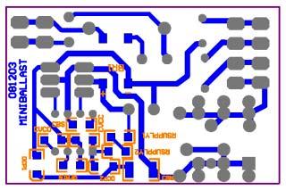
10 Figure 8.1: MINIBALLAST1 Layout 10
11 9. Design Tip: Auto-restart Option The design can be modified to include re-lamp/autorestart option as shown in Fig The resistors Rsupply must be moved across the upper lamp filament and the lamp connected to the bus voltage, instead than to ground. When the lamp is replaced, Rsupply together with the upper filament of the lamp provide a path from the DC bus to supply the micro-power current to the IR2520 and to restart the IR2520 as soon as VCC exceeds the UVLO+ threshold. Rsupply need to be able to handle high voltage. If using SMD components, 2 resistors are needed. RSUPPLY DCP2 F1 LF CF BR1 CBUS VCC 1 CVCC COM 2 FMIN 3 RFMIN VCO 4 IR2520 VB 8 HO 7 VS 6 LO 5 MHS CBS LRES CSNUB CDC LAMP CRES CVCO MLS DCP1 Fig. 9.1: Circuit Modification to include auto-restart option 11
12 10. Design Procedure to adapt the design to different lamps types The design with the IR2520D is very simple because it only has 2 control pins: VCO (0-5VDC oscillator voltage input) and FMIN (minimum frequency setting). To modify the design for a higher lamp power, you will need to modify RFMIN, CVCO, LRES and CRES. Make sure that FETs and inductors are rated to the current you need with the new lamp and that VCC is stable. To modify the design to a lower lamp power, you will need to decrease RFMIN and only in some case to modify also CVCO, LRES and CRES. In most cases you can use FETs and inductors with lower current ratings. Pin FMIN is connected to ground through a resistor (RFMIN). The value of this resistor programs the minimum frequency (fmin) of the IC and the starting frequency of the IC (2.5xfmin). The IR2520 will work in run mode at the minimum frequency unless non- ZVS is detected. Generally, to work with constant frequency, the minimum frequency needs to be chosen above the resonant frequency of the low-q R-C-L circuit. In this case, one can increase the value of RFMIN to decrease the frequency and increase the lamp power, or, decrease the value of RFMIN to increase the run frequency and decrease the lamp power. Pin VCO is connected to ground through a capacitor (CVCO). The value of this capacitor programs the time the frequency needs to ramp down from 2.5 times fmin (fmax) to fmin. One can increase the capacitor value to increase the preheat time, or, decrease the capacitor value to decrease the preheat time. The suggested design procedure is as follows: 1) Use the BDA software to calculate LRES and CRES. Select the input configuration without PFC, select the IR2156 IC and select single lamp current mode configuration. Select the new lamp in the database or add the lamp pa rameters by hand selecting the Advanced option. Calculate the operating point and chose the right values of L and C that satisfy: 1.1) Run frequency (best working range) 40-50KHz 1.2) C as small as possible to minimize losses (suggested value 4.7nF) 1.3) L values you have available 2) While measuring LO, apply 15V from pin VCC to pin COM and adjust the value of RFMIN to obtain the right minimum frequency (it is suggested set fmin = run frequency obtained with the BDA software). Increase RFMIN to decrease the minimum frequency or decrease RFMIN to increase the minimum frequency. 3) Apply the AC input and check preheat, ignition and run states of the lamp. 3.1) If the lamp ignites during preheat, the pre heat current is too small or the starting volt age across the lamp is too big, increase the value of CRES to decrease the voltage across the lamp during preheat and startup while increasing the preheat current. LRES may need to be decreased to maintain the same power and the same frequency. 3.2) If the IC works at a frequency > fmin, in crease CRES or LRES to decrease the reso nant frequency avoiding hard-switching, or, decrease the value of the snubber capaci tor CSNUBBER (a CSNUBBER minimum value of 680pF is suggested to make sure VCC stays above the UVLO-). 12
13 3.3) If VCC drops, increase the value of CSNUBBER or CVCC 4) Adjust the value of RFMIN to have the right power on the lamp (increase RFMIN to increase power or decrease RFMIN to decrease power) and the value of CVCO to set the correct preheat time (increase CVCO to increase the preheat time and decrease CVCO to decrease the preheat time). 5) Test the ballast over the entire input range and make sure that the frequency does not change dramatically in your working range. Select the value of RSUPPLY to have startup at the correct AC line voltage. Increase the value of RSUPPLY to start the IC at higher AC voltages and decrease the value of RSUPPLY to start the IC at lower AC voltages. 6) Test your lamp life (number of starts). A good design should guarantee at least 5,000 starts. To increase the number of starts, increase CRES or the preheat time (CVCO) WORLD HEADQUARTERS: 233 Kansas St., El Segundo, California Tel: (310) Data and specifications subject to change without notice. 3/14/
CFL Ballast for 26W/Spiral Lamp, 120VAC Input. By Cecilia Contenti. Functional Description
 International Rectifier 233 Kansas Street, El Segundo, CA 90245 TOPICS COVERED 1. Overview CFL Ballast for 26W/Spiral Lamp, 120VAC Input By Cecilia Contenti Overview Functional Description Features Fault
IRPLDIM4E. Miniature Dimmable 26W Ballast Using IRS2530D DIM8 TM Control IC. Table of Contents
 IRPLDIM4E Miniature Dimmable 26W Ballast Using IRS2530D DIM8 TM Control IC Table of Contents Page 1. Overview...2 2. Features...2 3. Electrical Characteristics...3 4. Fault Protection Characteristics...3
Application Note AN-1075
 Application Note AN-1075 Obtaining Low THD and high PF without A PFC By Cecilia Contenti and Peter Green Table of Contents Page I. Introduction...1 II. Test Results...1 III. Electrical Circuit...2 IV.
ADVANCE DATA DCP1 VCC 1 COM 2 FMIN 3 VB 8 HO 7 VS 6 IR2520D CVCC RFMIN CVCO
 ADVANCE DATA Data Sheet No. PD0 IR0D(S) ADAPTIVE BALLAST CONTROL IC Features 00V Driver Integrated Bootstrap Diode Adaptive zero-voltage switching (Z) Internal Crest Factor Over-Current Protection 0 to
IRPLDIM5E. 4 Level Switch Dim Fluorescent Ballast using the IRS2530D DIM8 TM. Table of Contents
 IRPLDIM5E 4 Level Switch Dim Fluorescent Ballast using the IRS2530D DIM8 TM Table of Contents Page 1. Features...2 2. Overview...2 3. Circuit Schematics...3 4. Functional Description...4 5. Fault Conditions...10
Application Note AN-1151
 Application Note AN-1151 IS168D Additional Design Information By T. ibarich Table of Contents Page Introduction... 1 Ballast Oscillator... Circuit..... 4 esonant Tank Output Circuit. 9 IC Start-Up and
IRPLCFL8U. Simplified Three Level Dimming CFL Fluorescent Ballast using the IRS2530D DIM8 TM. Table of Contents
 IRPLCFL8U Simplified Three Level Dimming CFL Fluorescent Ballast using the IRS2530D DIM8 TM Table of Contents Page 1. Features...2 2. Overview...2 3. Circuit Schematic...8 4. Electrical Characteristics...9
IRPLCFL1 POWIRLIGHT TM REFERENCE DESIGN : COMPACT BALLAST. Features. Circuit Schematic
 Reference Design Data Sheet (April, 1997) IRPLCFL1 POWIRLIGHT TM REFERENCE DESIGN : COMPACT BALLAST Features Drive 13W Compact Lamp 110 or 220 Vac Input High-Frequency Operation (34kHz) Soft Start with
IRPLLNR1 POWIRLIGHT TM REFERENCE DESIGN : LINEAR BALLAST. Features. Description. Block Diagram
 Reference Design Data Sheet (August, 1997) POWIRLIGHT TM REFERENCE DESIGN : LINEAR BALLAST Features Drive X40WT1 Universal Input (90-55Vac) High Power Factor (0.99) & Low THD High-Frequency Operation (40kHz)
ELECTRONIC BALLAST NIK MUHAMMAD FASHAN BIN HUSAIN
 ELECTRONIC BALLAST NIK MUHAMMAD FASHAN BIN HUSAIN This thesis is submitted as partial fulfillment of the requirements for the award of the Bachelor of Electrical Engineering (Hons.) (Electronics) Faculty
A New Power Factor Correction and Ballast Control IC
 A New Power Fact Crection Ballast Control IC Thomas J. Ribarich International Rectifier 33 Kansas St., El Segundo, CA, 95-3 tel. (3)7-7, fax. (3)7-, email: tribari@irf.com as presented to the IEEE Industry
Application Note AN-1214
 Application Note LED Buck Converter Design Using the IRS2505L By Ektoras Bakalakos Table of Contents Page 1. Introduction... 2 2. Buck Converter... 2 3. Peak Current Control... 5 4. Zero-Crossing Detection...
HIGH SPEED, 100V, SELF OSCILLATING 50% DUTY CYCLE, HALF-BRIDGE DRIVER
 Data Sheet No. 60206 HIGH SPEED, 100V, SELF OSCILLATING 50% DUTY CYCLE, HALF-BRIDGE DRIVER Features Simple primary side control solution to enable half-bridge DC-Bus Converters for 48V distributed systems
FAN7710V Ballast Control IC for Compact Fluorescent Lamps
 FAN7710V Ballast Control IC for Compact Fluorescent Lamps Features Integrated Half-Bridge MOSFET Floating Channel FAN7710V for Bootstrap Operation to +440V Low Startup and Operating Current: 120μA, 2.6mA
LD /15/2011. Green-Mode PWM Controller with Frequency Swapping and Integrated Protections. Features. General Description.
 12/15/2011 Green-Mode PWM Controller with Frequency Swapping and Integrated Protections Rev. 02a General Description The LD7536 is built-in with several functions, protection and EMI-improved solution
AN APPLICATION NOTE
 AN1694 - APPLICATION NOTE VIPower: ELECTRONIC BALLAST FOR REMOVABLE CFL N. Aiello S. Messina ABSTRACT This technical note describes how a High Frequency ballast based on VK05CFL is able to drive removable
DESCRIPTION FEATURES PROTECTION FEATURES APPLICATIONS. RS2320 High Accurate Non-Isolated Buck LED Driver
 High Accurate Non-Isolated Buck LED Driver DESCRIPTION RS2320 is especially designed for non-isolated LED driver. The building in perfect current compensation function ensures the accurate output current.
SELF-OSCILLATING FULL-BRIDGE DRIVER IC
 Data Sheet No. PD60259 ADVANCE INFOMATION IS2453D(S)PbF SELF-OSCILLATING FULL-BIDGE DIVE IC Features Integrated 600V Full-Bridge Gate Driver CT, T programmable oscillator 15.6V Zener Clamp on Micropower
N386X APPLICATION INFORMATION
 N386X APPLICATION INFORMATION Prepared by : Alex Leng The N386X is a low cost high integrated PWM primary switcher, it combines a current mode controller with a high voltage power MOSFET and integrates
Features. +12V to +36V MIC nf. High-Side Driver with Overcurrent Trip and Retry
 MIC0 MIC0 High-Speed High-Side MOSFET Driver General Description The MIC0 high-side MOSFET driver is designed to operate at frequencies up to 00kHz (khz PWM for % to 00% duty cycle) and is an ideal choice
Integrated Power Hybrid IC for Appliance Motor Drive Applications
 Integrated Power Hybrid IC for Appliance Motor Drive Applications PD-97277 Rev A IRAM336-025SB Series 3 Phase Inverter HIC 2A, 500V Description International Rectifier s IRAM336-025SB is a multi-chip Hybrid
High Accurate non-isolated Buck LED Driver
 High Accurate non-isolated Buck LED Driver Features High efficiency (More than 90%) High precision output current regulation (-3%~+3%) when universal AC input voltage (85VAC~265VAC) Lowest cost and very
ADVANCE DATA. Packages
 ADVANCE DATA Data Sheet No. PD6029 Features Intelligent half-bridge driver Auto Resetting Short Circuit Protection Auto Resetting Overload Protection Externally Triggerable Latching Shutdown Latching Overtemperature
HIGH SPEED, 100V, SELF OSCILLATING 50% DUTY CYCLE, FULL-BRIDGE DRIVER
 查询 IR2086S 供应商 捷多邦, 专业 PCB 打样工厂,24 小时加急出货 Data Sheet PD No.60226 IR2086S HIGH SPEED, 100V, SELF OSCILLATING 50% DUTY CYCLE, FULL-BRIDGE DRIVER Features Simple primary side control solution to enable full-bridge
LD7536R 05/11/2010. Green-Mode PWM Controller with Frequency Swapping and Integrated Protections. General Description. Features.
 05/11/2010 Green-Mode PWM Controller with Frequency Swapping and Integrated Protections Rev. 00 General Description The LD7536R is built-in with several functions, protection and EMI-improved solution
IRS2453(1)D(S) Product Summary
D(S) Product Summary") Features Integrated 600 V full-bridge gate driver CT, RT programmable oscillator 15.6 V Zener clamp on V CC Micropower startup Logic level latched shutdown pin Non-latched shutdown on CT pin (1/6th V CC
Features Integrated 600 V full-bridge gate driver CT, RT programmable oscillator 15.6 V Zener clamp on V CC Micropower startup Logic level latched shutdown pin Non-latched shutdown on CT pin (1/6th V CC
MAXREFDES121# Isolated 24V to 3.3V 33W Power Supply
 System Board 6309 MAXREFDES121# Isolated 24V to 3.3V 33W Power Supply Maxim s power-supply experts have designed and built a series of isolated, industrial power-supply reference designs. Each of these
S6510 Ballast Controller
 Semiconductor S6510 Ballast Controller Description The device provides simple and performance electronics ballast control function for the half bridge L/C resonant inverter. This device is optimized for
MAXREFDES116# ISOLATED 24V TO 5V 40W POWER SUPPLY
 System Board 6283 MAXREFDES116# ISOLATED 24V TO 5V 40W POWER SUPPLY Overview Maxim s power supply experts have designed and built a series of isolated, industrial power-supply reference designs. Each of
Self-Oscillating Half-Bridge Driver
 Self-Oscillating Half-Bridge Driver Features Product Summary Floating channel designed for bootstrap operation Integrated 600V half-bridge gate driver 15.6V zener clamp on Vcc True micropower start up
Preliminary GL8211/11B
 High Power Factor & Accuracy Constant Current LED Driver Features High Power Factor by One Cycle Control Accuracy Constant Current Low BOM Cost Linear Dimming on DIM Pin Average Current / Fixed Frequency
CR6842. Green-Power PWM Controller with Freq. Jittering. Features. Applications. General Description. Leading-edge blanking on Sense input
 Green-Power PWM Controller with Freq. Jittering Features Low Cost, Green-Power Burst-Mode PWM Very Low Start-up Current ( about 7.5µA) Low Operating Current ( about 3.0mA) Current Mode Operation Under
DESCRIPTION FEATURES APPLICATIONS TYPICAL APPLICATION
 MP5016 2.7V 22V, 1A 5A Current Limit Switch with Over Voltage Clamp and Reverse Block The Future of Analog IC Technology DESCRIPTION The MP5016 is a protection device designed to protect circuitry on the
Description. Part Number Package Pb-Free Operating Temperature Range Packing Method. Tube FAN7711MX 8-SOP. Yes -25 C ~ 125 C
 FAN7711 Ballast Control IC Features Floating Channel for Bootstrap Operation to +600V Low Start-up and Operating Current: 120μA, 3.2mA Under-Voltage Lockout with 1.8V of Hysteresis Adjustable Run Frequency
Power Management & Supply. Design Note. Version 2.3, August 2002 DN-EVALSF2-ICE2B765P-1. CoolSET 80W 24V Design Note for Adapter using ICE2B765P
 Version 2.3, August 2002 Design Note DN-EVALSF2-ICE2B765P-1 CoolSET 80W 24V Design Note for Adapter using ICE2B765P Author: Rainer Kling Published by Infineon Technologies AG http://www.infineon.com/coolset
Isolated High Side FET Driver
 UC1725 Isolated High Side FET Driver FEATURES Receives Both Power and Signal Across the Isolation Boundary 9 to 15 Volt High Level Gate Drive Under-voltage Lockout Programmable Over-current Shutdown and
DESIGN TIP DT Variable Frequency Drive using IR215x Self-Oscillating IC s. By John Parry
 DESIGN TIP DT 98- International Rectifier 233 Kansas Street El Segundo CA 9245 USA riable Frequency Drive using IR25x Self-Oscillating IC s Purpose of this Design Tip By John Parry Applications such as
ICB2FL02G. Smart Ballast Control IC for Fluorescent Lamp Ballasts. Power Management & Drives. Preliminary Datasheet V1.2
 Preliminary Datasheet ICB2FL02G Smart Ballast Control IC for Fluorescent Lamp Ballasts Published by Infineon Technologies AG http://www.infineon.com Power Management & Drives Never stop thinking ICB2FL02G
LD7523 6/16/2009. Smart Green-Mode PWM Controller with Multiple Protections. General Description. Features. Applications. Typical Application REV: 00
 6/16/2009 Smart Green-Mode PWM Controller with Multiple Protections REV: 00 General Description The LD7523 is a low startup current, current mode PWM controller with green-mode power-saving operation.
MP2313 High Efficiency 1A, 24V, 2MHz Synchronous Step Down Converter
 The Future of Analog IC Technology MP2313 High Efficiency 1A, 24V, 2MHz Synchronous Step Down Converter DESCRIPTION The MP2313 is a high frequency synchronous rectified step-down switch mode converter
IRAC1150-D2 Control Board User s Guide
 Computing & Communications SBU - AC-DC Applications Group 222 Kansas Street, El Segundo CA90245, California, USA IRAC1150-D2 Control Board User s Guide Rev. 2.0 7/6/2005 Rev. 2.0 7/6/2005 International
Features. RAMP Feed Forward Ramp/ Volt Sec Clamp Reference & Isolation. Voltage-Mode Half-Bridge Converter CIrcuit
 MIC3838/3839 Flexible Push-Pull PWM Controller General Description The MIC3838 and MIC3839 are a family of complementary output push-pull PWM control ICs that feature high speed and low power consumption.
DP9126IX. Non-Isolated Buck APFC Offline LED Power Switch FEATURES GENERAL DESCRIPTION APPLICATIONS TYPICAL APPLICATION CIRCUIT
 Non-Isolated Buck APFC Offline LED Power Switch DP9126IX FEATURES Active PFC for High PF and Low THD PF>0.9 with Universal Input Built-in HV Startup and IC Power Supply Circuit Internal 650V Power MOSFET
Current Mode PWM Power Switch. Code A B G H I J Year Code A B C Month Jan. Feb. Mar. Apr.
 Current Mode PWM Power Switch Preliminary GR8935 Features Current mode PWM ery low startup current Under-voltage lockout ULO Non-audible-noise green-mode control Fixed switching frequency of 50KHz Cycle-by-cycle
Using the EVM: PFC Design Tips and Techniques
 PFC Design Tips and Techniques Features: Bare die attach with epoxy Gold wire bondable Integral precision resistors Reduced size and weight High temperature operation Solder ready surfaces for flip chips
Resonant-Mode Power Supply Controllers
 Resonant-Mode Power Supply Controllers UC1861-1868 FEATURES Controls Zero Current Switched (ZCS) or Zero Voltage Switched (ZVS) Quasi-Resonant Converters Zero-Crossing Terminated One-Shot Timer Precision
IR2122(S) CURRENT SENSING SINGLE CHANNEL DRIVER
 CURRENT SENSING SINGLE CHANNEL DRIVER") Preliminary Data Sheet No. PD60130-K CURRENT SENSING SINGLE CHANNEL DRIVER Features Floating channel designed for bootstrap operation Fully operational to +600V Tolerant to negative transient voltage dv/dt
Preliminary Data Sheet No. PD60130-K CURRENT SENSING SINGLE CHANNEL DRIVER Features Floating channel designed for bootstrap operation Fully operational to +600V Tolerant to negative transient voltage dv/dt
SELF-OSCILLATING HALF BRIDGE
 Features Output Power MOSFETs in half-bridge configuration High side gate drive designed for bootstrap operation Bootstrap diode integrated into package (HD type) Accurate timing control for both Power
LD7536E 5/28/2012. Green-Mode PWM Controller with Frequency Swapping and Integrated Protections. General Description. Features.
 5/28/2012 Green-Mode PWM Controller with Frequency Swapping and Integrated Protections Rev. 00 General Description The is built-in with several functions, protection and EMI-improved solution in a tiny
Packages DCP1 DCP2 VCC CVCC1 COM CVCC2 CSD CSD CCS
 Data Sheet No. PD6029 rev.b Features Intelligent half-bridge driver Auto Resetting Short Circuit Protection Auto Resetting Overload Protection Externally Triggerable Latching Shutdown Latching Overtemperature
DESIGN TIP DT Managing Transients in Control IC Driven Power Stages 2. PARASITIC ELEMENTS OF THE BRIDGE CIRCUIT 1. CONTROL IC PRODUCT RANGE
 DESIGN TIP DT 97-3 International Rectifier 233 Kansas Street, El Segundo, CA 90245 USA Managing Transients in Control IC Driven Power Stages Topics covered: By Chris Chey and John Parry Control IC Product
Application Note AN-1052
 Application Note AN-05 Using the IR7x Linear Current Sensing ICs By Jonathan Adams. Basic Functionality.... Bootstrap Circuit... 3. Retrieving Analog Current Signal at the Output... 3. Passive Filters...
User Guide #0601. IRDC W Reference Design Rev By Weidong Fan. Table of Contents Page Overview... 2
 User Guide #0601 IRDC2086-330W Reference Design Rev. 2-28-06 By Weidong Fan Table of Contents Page Overview... 2 Board Description & Circuit Capability... 2 Layout... 7 Bill of Material... 8 1 Overview
IRDC3822A. Rev /22/2008 1
 02/22/2008 SupIRBuck TM DESCRIPTION USER GUIDE FOR IR3822A EVALUATION BOARD The IR3822A is a synchronous buck converter, providing a compact, high performance and flexible solution in a small 5mmx6mm Power
IRS254(0,1)SPbF LED BUCK REGULATOR CONTROL IC. Not recommended for new design. Features
SPbF LED BUCK REGULATOR CONTROL IC. Not recommended for new design. Features") Not recommended for new design Data Sheet No. PD60293 IRS254(0,1)(S)PbF LED BUCK REGULATOR CONTROL IC Description The IRS254(0,1) are high voltage, high frequency buck control ICs for constant LED current
Not recommended for new design Data Sheet No. PD60293 IRS254(0,1)(S)PbF LED BUCK REGULATOR CONTROL IC Description The IRS254(0,1) are high voltage, high frequency buck control ICs for constant LED current
POWER MANAGEMENT PRODUCTS. Application Note. Simple PWM Boost Converter with I/O Disconnect Solves Malfunctions Caused when V OUT <V IN
 POWER MANAGEMENT PRODUCTS Application Note Simple PWM Boost Converter with I/O Disconnect Solves Malfunctions Caused when V OUT
SR A, 30V, 420KHz Step-Down Converter DESCRIPTION FEATURES APPLICATIONS TYPICAL APPLICATION
 SR2026 5A, 30V, 420KHz Step-Down Converter DESCRIPTION The SR2026 is a monolithic step-down switch mode converter with a built in internal power MOSFET. It achieves 5A continuous output current over a
FL103 Primary-Side-Regulation PWM Controller for LED Illumination
 FL103 Primary-Side-Regulation PWM Controller for LED Illumination Features Low Standby Power: < 30mW High-Voltage Startup Few External Component Counts Constant-Voltage (CV) and Constant-Current (CC) Control
Features MIC5022 C TH. Sense H+ C TL. Sense L. DC Motor Control Application
 MIC0 MIC0 Half-Bridge MOSFET Driver Not Recommended for New Designs General Description The MIC0 half-bridge MOSFET driver is designed to operate at frequencies up to 00kHz (khz PWM for % to 00% duty cycle)
15 W HVDCP Quick Charge 3.0 Compatible CV/CC Charger
 Design Note 15 W HVDCP Quick Charge 3.0 Compatible CV/CC Charger Device Application Input Voltage NCP4371AAC NCP1361EABAY NCP4305D Quick Charge 3.0, Cell Phone, Laptop Charger Output Voltage Output Ripple
A Novel Single-Stage Push Pull Electronic Ballast With High Input Power Factor
 770 IEEE TRANSACTIONS ON INDUSTRIAL ELECTRONICS, VOL. 48, NO. 4, AUGUST 2001 A Novel Single-Stage Push Pull Electronic Ballast With High Input Power Factor Chang-Shiarn Lin, Member, IEEE, and Chern-Lin
Features. Slope Comp Reference & Isolation
 MIC388/389 Push-Pull PWM Controller General Description The MIC388 and MIC389 are a family of complementary output push-pull PWM control ICs that feature high speed and low power consumption. The MIC388/9
Preliminary GR8875N Series
 Green-Mode PWM Controller with High Voltage Startup Circuit Features High-Voltage (700V) Startup Circuit Very Low Startup Current (
IR11682S DUAL SmartRectifier TM DRIVER IC
 Datasheet No 97476 July 1, 2011 Features Secondary-side high speed controller for synchronous rectification in resonant half bridge topologies 200V proprietary IC technology Max 400KHz switching frequency
AN2524 Application note
 Application note 54 W / T5 ballast driven by the L6585D Introduction This application note describes a demo board able to drive a 54 W linear T5 fluorescent lamp. The ballast control is done by the L6585D
Application of E-Fuse in a DC/DC converter. No Smoke, No Fire
 Application of E-Fuse in a DC/DC converter No Smoke, No Fire 1 Want to Avoid Burnt Units 2 Want to Avoid Burnt Motherboards 3 Output Over Voltage Common Output Over Voltage Protection Schemes PWM controller
Figure 1 RC Based Soft Start Circuit. Path of charge during startup shown in red.
 P a g e 1 1 Effects of Gate RC Soft Start The LM25066A has a power-limiting feature to help protect the external MOSFET (keep it operating under its SOA curve). However, for designs with large load currents
HM V 2A 500KHz Synchronous Step-Down Regulator
 Features HM8114 Wide 4V to 30V Operating Input Range 2A Continuous Output Current Fixed 500KHz Switching Frequency No Schottky Diode Required Short Protection with Hiccup-Mode Built-in Over Current Limit
Application Note AN-1144
 Application Note AN-1144 IRS20957S Functional Description By Jun Honda, Xiao-chang Cheng Table of Contents Floating PWM Input... 2 Over-Current Protection (OCP)... 3 Protection Control... 5 Self Reset
200V HO V DD V B HIN SD HIN SD V S TO LOAD LIN V CC V SS LIN COM LO
 Data Sheet No. PD6195-E Features Floating channel designed for bootstrap operation Fully operational to Tolerant to negative transient voltage, dv/dt immune Gate drive supply range from 1 to V Undervoltage
IX Evaluation Board User s Guide INTEGRATED CIRCUITS DIVISION. 1. Introduction. 1.1 Features:
 IX844 Evaluation Board User s Guide. Introduction IXYS Integrated Circuits Division's IX844 evaluation board contains all the necessary circuitry to demonstrate the features of a high voltage gate driver
IS31LT3932 HIGH PF LOW THD UNIVERSAL LED DRIVER. December 2013
 HIGH PF LOW THD UNIVERSAL LED DRIVER GENERAL DESCRIPTION IS31LT3932 is a universal LED driver, which can operate in fly-back, buck-boost and buck convertor. For isolation fly-back, it can achieve high
SupIRBuck TM IRDC3840W USER GUIDE FOR IR3840W EVALUATION BOARD DESCRIPTION BOARD FEATURES
 SupIRBuck TM DESCRIPTION USER GUIDE FOR IR3840W EVALUATION BOARD The IR3840W is a synchronous buck converter, providing a compact, high performance and flexible solution in a small 5mmx6mm Power QFN package.
Current-Mode PWM Multiple Output Flyback Converter
 Introduction Current-Mode PWM Multiple Output Flyback Converter The Supertex evaluation board demonstrates the features of HV606 IC by presenting a DC/DC converter employing flyback technique to achieve
Green-Mode PWM Controller with Integrated Protections
 Green-Mode PWM Controller with Integrated Protections Features Current mode PWM Very low startup current Under-voltage lockout (UVLO) Non-audible-noise green-mode control Programmable switching frequency
D8020. Universal High Integration Led Driver Description. Features. Typical Applications
 Universal High Integration Led Driver Description The D8020 is a highly integrated Pulse Width Modulated (PWM) high efficiency LED driver IC. It requires as few as 6 external components. This IC allows
IR2112(S) HIGH AND LOW SIDE DRIVER. Features. Product Summary. Packages. Description. Typical Connection V OFFSET. 600V max. 200 ma / 420 ma 10-20V
 HIGH AND LOW SIDE DRIVER. Features. Product Summary. Packages. Description. Typical Connection V OFFSET. 600V max. 200 ma / 420 ma 10-20V") Features Floating channel designed for bootstrap operation Fully operational to +V Tolerant to negative transient voltage dv/dt immune Gate drive supply range from 1 to 2V Undervoltage lockout for both
Features Floating channel designed for bootstrap operation Fully operational to +V Tolerant to negative transient voltage dv/dt immune Gate drive supply range from 1 to 2V Undervoltage lockout for both
LM5034 High Voltage Dual Interleaved Current Mode Controller with Active Clamp
 High Voltage Dual Interleaved Current Mode Controller with Active Clamp General Description The dual current mode PWM controller contains all the features needed to control either two independent forward/active
FAN7387V Ballast Control IC for Compact Fluorescent Lamp
 FAN7387V Ballast Control IC for Compact Fluorescent Lamp Features Integrated Half-Bridge MOSFET Internal Clock Using RCT Enable External Sync Function Using RCT Dead-Time Control by using Resistor Shut
Interleaved PFC technology bring up low ripple and high efficiency
 Interleaved PFC technology bring up low ripple and high efficiency Tony Huang 黄福恩 Texas Instrument Sept 12,2007 1 Presentation Outline Introduction to Interleaved transition mode PFC Comparison to single-channel
SELF-OSCILLATING HALF-BRIDGE DRIVER V OFFSET. Packages
 Preliminary Data Sheet No. PD60131L SELFOSCILLATING HALFBIDGE DIVE Features Integrated 600V halfbridge gate driver 15.6V zener clamp on Vcc True micropower start up Tighter initial deadtime control Low
Self Oscillating 25W CFL Lamp Circuit
 APPLICATION NOTE Self Oscillating 25W CFL Lamp Circuit TP97036.2/F5.5 Abstract A description is given of a self oscillating CFL circuit (demo board PR39922), which is able to drive a standard Osram Dulux
SOT-23 Boost PFC Control IC
 µpfc TM Features Critical-conduction mode PFC control High PF and ultra-low THD Wide load and line range Regulated and programmable DC bus voltage No secondary winding required MOSFET cycle-by-cycle over-current
Presentation Content Review of Active Clamp and Reset Technique in Single-Ended Forward Converters Design Material/Tools Design procedure and concern
 Active Clamp Forward Converters Design Using UCC2897 Hong Huang August 2007 1 Presentation Content Review of Active Clamp and Reset Technique in Single-Ended Forward Converters Design Material/Tools Design
HM V 3A 500KHz Synchronous Step-Down Regulator
 Features Wide 4V to 18V Operating Input Range 3A Continuous Output Current 500KHz Switching Frequency Short Protection with Hiccup-Mode Built-in Over Current Limit Built-in Over Voltage Protection Internal
SupIRBuck TM IRDC3839 USER GUIDE FOR IR3839 EVALUATION BOARD DESCRIPTION BOARD FEATURES
 SupIRBuck TM DESCRIPTION USER GUIDE FOR IR3839 EVALUATION BOARD The IR3839 SupIRBuck TM is an easy-to-use, fully integrated and highly efficient DC/DC regulator. The onboard PWM controller and MOSFETs
Fixed with 65kHz (AP3125A/V/R/L/B/ST) 100kHz (AP3125HA/HB) VFB Resistor 10kΩ 15kΩ. Standby Performance Better Best
 100kHz (AP3125HA/HB) VFB Resistor 10kΩ 15kΩ. Standby Performance Better Best") APPLICATION NOTE 1120 GREEN MODE PWM CONTROLLER Introduction The AP3125 series is a low start-up current, current mode PWM controller with green-mode power-saving operation. AP3125 series PWM switching
APPLICATION NOTE 1120 GREEN MODE PWM CONTROLLER Introduction The AP3125 series is a low start-up current, current mode PWM controller with green-mode power-saving operation. AP3125 series PWM switching
ML4818 Phase Modulation/Soft Switching Controller
 Phase Modulation/Soft Switching Controller www.fairchildsemi.com Features Full bridge phase modulation zero voltage switching circuit with programmable ZV transition times Constant frequency operation
SupIRBuck TM IRDC3841W USER GUIDE FOR IR3841W EVALUATION BOARD DESCRIPTION BOARD FEATURES
 IRDC384W SupIRBuck TM DESCRIPTION USER GUIDE FOR IR384W EVALUATION BOARD The IR384W is a synchronous buck converter, providing a compact, high performance and flexible solution in a small 5mmx6mm Power
HIGH SPEED, 100V, SELF OSCILLATING 50% DUTY CYCLE, FULL-BRIDGE DRIVER. V CC (max) V offset(max)
 V offset(max)") Data heet PD No.60226 revb HIGH PEED, 100V, ELF OCILLATING 50% DUTY CYCLE, FULL-BRIDGE DRIVER Features imple primary side control solution to enable full-bridge DC-Bus Converters for 48V distributed systems
Data heet PD No.60226 revb HIGH PEED, 100V, ELF OCILLATING 50% DUTY CYCLE, FULL-BRIDGE DRIVER Features imple primary side control solution to enable full-bridge DC-Bus Converters for 48V distributed systems
Application Note AN-1173
 Application Note AN-1173 Power Factor Correction using the IRS500 By Peter B. Green Table of Contents Page 1. Introduction.... Power Factor and THD...3 3. PFC Boost Pre-regulator...5 4. Design Equations...11
Designing A Medium-Power Resonant LLC Converter Using The NCP1395
 Designing A Medium-Power Resonant LLC Converter Using The NCP395 Prepared by: Roman Stuler This document describes the design procedure needed to implement a medium-power LLC resonant AC/DC converter using
Green-Mode PWM Controller with Integrated Protections
 Green-Mode PWM Controller with Integrated Protections Features Current mode control Very low startup current Under-voltage lockout (UVLO) Non-audible-noise green-mode control Programmable switching frequency
LM5021 AC-DC Current Mode PWM Controller
 AC-DC Current Mode PWM Controller General Description The LM5021 off-line pulse width modulation (PWM) controller contains all of the features needed to implement highly efficient off-line single-ended
Packages. Crossconduction. Input logic. Part. prevention logic COM HIN/LIN no none 21814
 Data Sheet No. PD014-D Features Floating channel designed for bootstrap operation Fully operational to +00V Tolerant to negative transient voltage dv/dt immune Gate drive supply range from 10 to 20V Undervoltage
Green-Mode PWM Controller with Hiccup Protection
 Green-Mode PWM Controller with Hiccup Protection Features Current Mode Control Standby Power below 100mW Under-Voltage Lockout (UVLO) Non-Audible-Noise Green-Mode Control 65KHz Switching Frequency Internal
MP A, 30V, 420kHz Step-Down Converter
 The Future of Analog IC Technology DESCRIPTION The MP28490 is a monolithic step-down switch mode converter with a built in internal power MOSFET. It achieves 5A continuous output current over a wide input
LD7577 1/15/2009. High Voltage Green-Mode PWM Controller with Brown-Out Protection. General Description. Features. Applications. Typical Application
 Rev. 01 General Description High Voltage Green-Mode PWM Controller with Brown-Out Protection The LD7577 integrates several functions of protections, and EMI-improved solution in SOP-8 package. It minimizes
Design Consideration with AP3041
 Design Consideration with AP3041 Application Note 1059 Prepared by Yong Wang System Engineering Dept. 1. Introduction The AP3041 is a current-mode, high-voltage low-side channel MOSFET controller, which
FAN6751MR Highly-Integrated Green-Mode PWM Controller
 FAN6751MR Highly-Integrated Green-Mode PWM Controller Features High-Voltage Startup Low Operating Current: 4mA Linearly Decreasing PWM Frequency to 18KHz Fixed PWM Frequency: 65KHz Peak-current-mode Control