Military Radome Performance and Verification Testing Thomas B. Darling Vice President, Customer Support MI Technologies
|
|
|
- Juliet Lloyd
- 6 years ago
- Views:
Transcription
1 Military Radome Performance and Verification Testing Thomas B. Darling Vice President, Customer Support MI Technologies Incredible efforts are made by system designers to produce state-of-the-art radar and other RF based capabilities for our military. Modern radar systems are used for various purposes including, but not limited to: weather assessment; navigation; terrain following/terrain avoidance; weapons fire control; electronic warfare; enemy tracking, listening and identification, etc. Dependant upon extremely high measurement precision, repeatability and accuracy, these radar systems all require protection from the elements. While many think about the exotic hardware and sexy looking screen shots produced by these sophisticated radar systems, most do not think about one extremely critical component of these systems: the radar dome or radome. When one considers the critical need for proper operation of these systems for our military, as well as the harsh conditions during conflicts, this component protects vital systems which can make the difference between survival and disaster. The most well recognized radome is the one positioned on the nose of an aircraft or missile. However, many military applications, and new commercial applications, are positioning microwave based systems in other locations on the aircraft. These often require odd shapes in order to protect the RF system and to be sufficiently aerodynamic. Military radome testing is, not surprisingly, considerably more involved than for commercial applications. Typical Measurement Parameters Some of the typical parameters measured to characterize the performance of a radome include: Transmission Efficiency (TE) Transmission Efficiency is the percentage of microwave energy that passes through a radome, typically measured over various angular regions (which usually represent the area of the radome actually used by the radar system). It is measured by comparing power levels received by a test antenna in two different conditions. A reference measurement is made with the radome off, then again after installation of the radome over the radar antenna. The resulting data is plotted over the surface of the radome. While ideally transparent, all radomes will have losses as the RF signal passes through it due to a combination of reflections, diffraction, absorption, refraction and depolarization. Beam Deflection (BD)/ Boresight Shift (BS) Beam Deflection is the change in the direction of propagation of the microwave signal as it passes through the radome. If one considers the geometry associated with the tracking of a fast moving enemy target or terrain avoidance for a low flying, fast moving aircraft, even very small angular errors introduced by the radome can have significant effects. (For test antennas with a tracking null, the term boresight shift is often used interchangeably with Beam Deflection. Beam Deflection can then be a term reserved for the case of a sum beam.) Reflectivity Reflectivity is the change in the magnitude of the reflection coefficient at the port of the radar antenna which is caused by the presence of the radome. This is measured using a reflectometer with a remote head. The reflection coefficient is measured before and after the radome is installed with the antenna pointing out into a reflection-less environment (such as an anechoic chamber or an outdoor range). Ideally, this measurement is independent of pointing direction of the radar antenna. 1
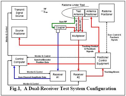
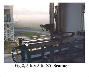
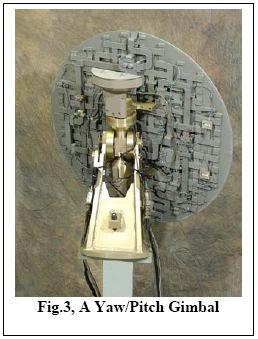
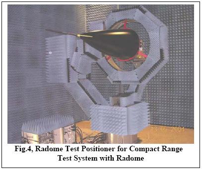
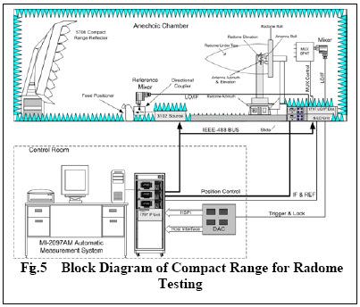
2 Antenna Pattern Distortion Pattern distortion is the change to the radar antenna radiation pattern caused by the presence of the protective radome. Patterns are taken with and without the radome present. Various analyses can be made to assess the changes to the pattern shape including: beam width, side lobe levels, peak/null location, lobe imbalance, null fill, etc. This requires that the radar antenna rotate with the radome to maintain a particular antenna to radome aspect as the antenna pattern is measured. Measurement Approaches There are several approaches typically employed to measure radome performance. The three most common are described below. While the details of the mechanical positioning system can be very different for each approach, a basic test system includes a control computer, transmit signal source, source positioner, radome positioner, position control equipment, test antenna, RF signal multiplexer and the receiver. Far Field Testing Traditional radome testing has often employed an outdoor far field test range. While outdoor testing has its own inherent disadvantages, the relatively long length of the range allows for slightly less precision in the mechanical positioning systems (as compared to the use of a Compact Range). TE and BD may be measured with a single receiver by sequentially switching between ports of the tracking antenna. To measure BD, the radar antenna positioner actively tracks the boresight of the illuminating wave front, first with the radome installed and then without it. Serving dual use, the receiver provides a tracking signal for BD or to extract amplitude data for TE measurements. The test antenna positioner is typically an XY scanner. The test antenna must be a tracking antenna that operates using one of the typical techniques such as monopulse differences, conical scanning or sequential lobing. TE data can be acquired from the sum channel vs. radome position data. An enhanced architecture for BD and TE which employs two receivers is shown in Figure 1. Receiver #1 processes the TE data and receiver #2 processes the BD data. Receiver #2 (the tracking receiver) requires three signal inputs from the tracking antenna (sum, delta azimuth, delta elevation). The sum RF channel is coupled directly to receiver #1 and passed to receiver #2 via the multiplexer. Receiver #1 process the sum channel, extracting the amplitude data required for the TE measurement. Receiver #2 processes the sum channel, delta azimuth channel and the delta elevation channel signals, generating the tracking errors required to make the BD measurement. Both receivers operate simultaneously and independently. The system can be configured to track either with a XY scanner (see Figure 2) or the antenna gimbal (see Figure 3). A null seeker positioner is normally used to translate continuously the transmit antenna to the apparent electrical boresight direction of the antenna radome combination. Compact Range (CR) Testing Many systems employ a compact range reflector in an indoor range to create plane wave illumination of the test article. A CR range, a device for producing a localized plane wave within a confined space, operates by collimating an RF point source with a paraboloidal reflector. Avoiding problems associated with weather and other outdoor anomalies, the CR provides the security required by military test programs and utilizes a stable indoor test environment. See Figures 4 & 5. Near Field (NF) Testing A continuing trend for antenna measurement technology has been the migration to near field scanning techniques. The ever increasing speed of digital computers and the reduced size of a near field range compared to other test methods is driving this change. Near field scanning is recognized for the excellent radiation pattern accuracy. Since radome measurements entail 2
3 ascertaining the difference between two radiation patterns, it is understandable that near field measurements yield an accurate measure of radome performance. However, closed loop BD tracking functions are unavailable. See Figures 6 & 7. Required Accuracy TE accuracy or repeatability is typically specified as +/-2% of full power. This corresponds to +/ db, and can be extremely difficult to achieve. The difficulty increases if there are moving RF cables, if the radar antenna must counter-steer the radome positioner to maintain alignment with the range antenna, or if a significant amount of time elapses between measurements with the radome off. Boresight shift (BS) is typically specified to about +/-0.1 mrad, or +/ degrees. This can also be difficult to achieve. This deflection is normally measured by aligning the radar antenna to the incident field (or vice versa) with and without the radome mounted, and reporting the angular difference between the two measurements. Two common geometries for measuring boresight shift use either a two axis gimbal inside the radome or a down range XY translation stage. The down range scanner becomes easier to get in spec as the distance increases. The gimbal approach is always difficult, since the accuracy of a typical high-precision gimbal rarely exceeds the accuracy required at the system level. Both TE and BS are measured with the radar antenna and range antenna always pointing directly at each other. The simplest and most accurate positioning geometry for these parameters generally has the radar antenna mounted on a stationary post secured to the floor. The combination of radome shape, system antenna insertion depth, and required angular coverage sometimes precludes the use of this simple geometry. Pattern distortion measurements, are made by rotating the radome and radar antenna together to obtain the antenna pattern with and without the radome. When pattern distortion measurements are required along with TE and/or BS measurements, a positioning system with two different modes of operation is needed. Sometimes the antenna and radome rotate together, but sometimes the radome rotates while the antenna remains stationary. Radome Construction & Repair Normal flight operation of aircraft will subject the radome to significant thermal stresses, as well as other deleterious effects such as bird strikes, hail and rain exposure. Rain can cause moisture to migrate into the potentially porous radome materials. Even small amounts of water, which may wick into the fibrous materials, will freeze at altitude causing delamination of layers. This can create a progressive failure of the radome materials. Typically manufactured from a variety of composite materials and a metallic mounting ring, radomes are often comprised of multiple layers of different materials. The radome will be coated with various specialized paints targeting various properties (to minimize rain erosion, static build up, etc). While materials and conditions are readily controlled during the initial manufacture, most radomes are expected to have a long life which will include multiple repair cycles. Control of repair materials and repair procedures is critical to the proper performance of the repaired radome in the field. Once repaired, the radome performance must be verified to the applicable standards or established test requirements. Many measurement systems will yield test data expressed as test positioner aspect angles, based upon the coordinate system employed by the measurement system. This can create a problem for those folks attempting to repair the radome, who need to know where the problem exists on the radome surface. Advanced systems employ three dimensional models of the radome surface to translate test results from the test positioner coordinate system onto a 3D isometric view of the radome. Adding aircraft coordinates to the test results (such as fuselage station, waterline and buttline) and displaying failing results in a 3
4 graphical manner provides more meaningful data in useful terms for the composite repair personnel. With such data, they can more easily identify and minimize the area to be repaired. See Figure 8. Conclusion Proper radar system operation on aircraft requires known radome performance. Normal use of aircraft will subject radomes to conditions which will likely affect its performance over time. Commercial aircraft operated in the US are subject to requirements specified by the Federal Aviation Administration. In the interest of safety and reliability of radomes following damage, the FAA issued Advisory Circular stating that all repairs to a radome, no matter how minor, should return the radome to its original or properly altered condition, both electrically and structurally. If a repair adds or replaces skin plies, electrical testing must be performed using the techniques and procedures of the Aircraft Technical Committee report ARTC-4, Electrical Test Procedure for Radomes and Radome Material. Additional radome test requirements are called out by DO-213, Minimal Operational Performance Standards for Nose-Mounted Radomes. This specification was originally developed by the Radio Technical Commission for Aeronautics (RTCA) in response to the development of predictive windshear weather radar systems. This document specifies the tests to perform on both a new and repaired commercial radomes. Testing for repaired commercial radomes is normally limited to transmission efficiency only and most radome repair shops test to this standard. New radomes are additionally tested for boresight error, antenna sidelobe degradation and incident reflection. Military requirements, however, are very stringent and usually require more sophisticated measurement approaches (than for commercial requirements). The test requirements for military radome applications are usually specified by the original supplier of the radar system for the aircraft. The radome is, after all, an integral part of the complete radar system. Generating unique performance requirements for each airframe, the test system supplier must then help determine the optimal approach based upon the test requirements, available test facilities and test throughput requirements. MI Technologies has produced numerous radome testing systems for both commercial and military applications. Delivering test systems and routine test services for missile radomes, wing tip radomes and other shapes (in addition to nose radomes), MI has employed all of the techniques discussed here. Working with military contractors, MI has delivered test systems and/or radome testing services for: F1, F15, F16, F18 and Gripen fighters; MC-130E military transports; B-737 and MD-80 commercial aircraft; PAC-3 missiles, and numerous other military, as well as commercial, radomes. Thomas B. Darling Vice President, Customer Support MI Technologies tdarling@mi-technologies.com References: 1. D.W. Hess, R. Luna, J. McKenna, Electromagnetic Radome Measurements: A Review of Automated Systems, Loughborough Antennas and Propagation Conference Proceedings R. Luna, T. Thomas, D. Darsey, J. Vortmeier, A Dual Receiver Method for Simultaneous Measurements of Radome Transmission Efficiency and Beam Deflection, AMTA Proceedings
5 5
6 6


7 Figure 8: 3D Plot of TE Results on MC-130E Radome 7
A DUAL-RECEIVER METHOD FOR SIMULTANEOUS MEASUREMENTS OF RADOME TRANSMISSION EFFICIENCY AND BEAM DEFLECTION
 A DUAL-RECEIVER METHOD FOR SIMULTANEOUS MEASUREMENTS OF RADOME TRANSMISSION EFFICIENCY AND BEAM DEFLECTION Robert Luna MI Technologies, 4500 River Green Parkway, Suite 200 Duluth, GA 30096 rluna@mi-technologies.com
INDOOR AUTOMATIC F-16 FIRE CONTROL ANTENNA AND RADOME TEST FACILITIES
 INDOOR AUTOMATIC F-16 FIRE CONTROL ANTENNA AND RADOME TEST FACILITIES ABSTRACT by Joseph J. Anderson MI Technologies was selected by the United States Air Force to design and install a complete turn-key
AN AUTOMATED CYLINDRICAL NEAR-FIELD MEASUREMENT AND ANALYSIS SYSTEM FOR RADOME CHARACTERIZATION
 AN AUTOMATED CYLINDRICAL NEAR-FIELD MEASUREMENT AND ANALYSIS SYSTEM FOR RADOME CHARACTERIZATION Matthew Giles David Florida Laboratory/Canadian Space Agency 371 Carling Avenue Ottawa, Ontario, Canada K2S
Using Frequency Diversity to Improve Measurement Speed Roger Dygert MI Technologies, 1125 Satellite Blvd., Suite 100 Suwanee, GA 30024
 Using Frequency Diversity to Improve Measurement Speed Roger Dygert MI Technologies, 1125 Satellite Blvd., Suite 1 Suwanee, GA 324 ABSTRACT Conventional antenna measurement systems use a multiplexer or
INTRODUCTION. Basic operating principle Tracking radars Techniques of target detection Examples of monopulse radar systems
 Tracking Radar H.P INTRODUCTION Basic operating principle Tracking radars Techniques of target detection Examples of monopulse radar systems 2 RADAR FUNCTIONS NORMAL RADAR FUNCTIONS 1. Range (from pulse
HOW TO CHOOSE AN ANTENNA RANGE CONFIGURATION
 HOW TO CHOOSE AN ANTENNA RANGE CONFIGURATION Donnie Gray Nearfield Systems, Inc. 1330 E. 223 rd St, Bldg 524 Carson, CA 90745 (310) 518-4277 dgray@nearfield.com Abstract Choosing the proper antenna range
1 SINGLE TGT TRACKER (STT) TRACKS A SINGLE TGT AT FAST DATA RATE. DATA RATE 10 OBS/SEC. EMPLOYS A CLOSED LOOP SERVO SYSTEM TO KEEP THE ERROR SIGNAL
 TRACKS A SINGLE TGT AT FAST DATA RATE. DATA RATE 10 OBS/SEC. EMPLOYS A CLOSED LOOP SERVO SYSTEM TO KEEP THE ERROR SIGNAL") TRACKING RADARS 1 SINGLE TGT TRACKER (STT) TRACKS A SINGLE TGT AT FAST DATA RATE. DATA RATE 10 OBS/SEC. EMPLOYS A CLOSED LOOP SERVO SYSTEM TO KEEP THE ERROR SIGNAL SMALL. APPLICATION TRACKING OF AIRCRAFT/
TRACKING RADARS 1 SINGLE TGT TRACKER (STT) TRACKS A SINGLE TGT AT FAST DATA RATE. DATA RATE 10 OBS/SEC. EMPLOYS A CLOSED LOOP SERVO SYSTEM TO KEEP THE ERROR SIGNAL SMALL. APPLICATION TRACKING OF AIRCRAFT/
A CYLINDRICAL NEAR-FIELD VS. SPHERICAL NEAR-FIELD ANTENNA TEST COMPARISON
 A CYLINDRICAL NEAR-FIELD VS. SPHERICAL NEAR-FIELD ANTENNA TEST COMPARISON Jeffrey Fordham VP, Sales and Marketing MI Technologies, 4500 River Green Parkway, Suite 200 Duluth, GA 30096 jfordham@mi-technologies.com
A TECHNIQUE TO EVALUATE THE IMPACT OF FLEX CABLE PHASE INSTABILITY ON mm-wave PLANAR NEAR-FIELD MEASUREMENT ACCURACIES
 A TECHNIQUE TO EVALUATE THE IMPACT OF FLEX CABLE PHASE INSTABILITY ON mm-wave PLANAR NEAR-FIELD MEASUREMENT ACCURACIES Daniël Janse van Rensburg Nearfield Systems Inc., 133 E, 223rd Street, Bldg. 524,
ANECHOIC CHAMBER DIAGNOSTIC IMAGING
 ANECHOIC CHAMBER DIAGNOSTIC IMAGING Greg Hindman Dan Slater Nearfield Systems Incorporated 1330 E. 223rd St. #524 Carson, CA 90745 USA (310) 518-4277 Abstract Traditional techniques for evaluating the
MITIGATING INTERFERENCE ON AN OUTDOOR RANGE
 MITIGATING INTERFERENCE ON AN OUTDOOR RANGE Roger Dygert MI Technologies Suwanee, GA 30024 rdygert@mi-technologies.com ABSTRACT Making measurements on an outdoor range can be challenging for many reasons,
GAIN COMPARISON MEASUREMENTS IN SPHERICAL NEAR-FIELD SCANNING
 GAIN COMPARISON MEASUREMENTS IN SPHERICAL NEAR-FIELD SCANNING ABSTRACT by Doren W. Hess and John R. Jones Scientific-Atlanta, Inc. A set of near-field measurements has been performed by combining the methods
Antenna Measurement Uncertainty Method for Measurements in Compact Antenna Test Ranges
 Antenna Measurement Uncertainty Method for Measurements in Compact Antenna Test Ranges Stephen Blalock & Jeffrey A. Fordham MI Technologies Suwanee, Georgia, USA Abstract Methods for determining the uncertainty
Accuracy Estimation of Microwave Holography from Planar Near-Field Measurements
 Accuracy Estimation of Microwave Holography from Planar Near-Field Measurements Christopher A. Rose Microwave Instrumentation Technologies River Green Parkway, Suite Duluth, GA 9 Abstract Microwave holography
A BROADBAND POLARIZATION SELECTABLE FEED FOR COMPACT RANGE APPLICATIONS
 A BROADBAND POLARIZATION SELECTABLE FEED FOR COMPACT RANGE APPLICATIONS Carl W. Sirles ATDS Howland 454 Atwater Court, Suite 17 Buford, GA 3518 Abstract Many aircraft radome structures are designed to
Estimating Measurement Uncertainties in Compact Range Antenna Measurements
 Estimating Measurement Uncertainties in Compact Range Antenna Measurements Stephen Blalock & Jeffrey A. Fordham MI Technologies Suwanee, Georgia, USA sblalock@mitechnologies.com jfordham@mitechnolgies.com
A COMPOSITE NEAR-FIELD SCANNING ANTENNA RANGE FOR MILLIMETER-WAVE BANDS
 A COMPOSITE NEAR-FIELD SCANNING ANTENNA RANGE FOR MILLIMETER-WAVE BANDS Doren W. Hess dhess@mi-technologies.com John McKenna jmckenna@mi-technologies.com MI-Technologies 1125 Satellite Boulevard Suite
Advances in Antenna Measurement Instrumentation and Systems
 Advances in Antenna Measurement Instrumentation and Systems Steven R. Nichols, Roger Dygert, David Wayne MI Technologies Suwanee, Georgia, USA Abstract Since the early days of antenna pattern recorders,
The Design of an Automated, High-Accuracy Antenna Test Facility
 The Design of an Automated, High-Accuracy Antenna Test Facility T. JUD LYON, MEMBER, IEEE, AND A. RAY HOWLAND, MEMBER, IEEE Abstract This paper presents the step-by-step application of proven far-field
High Performance S and C-Band Autotrack Antenna
 High Performance S and C-Band Autotrack Antenna Item Type text; Proceedings Authors Lewis, Ray Publisher International Foundation for Telemetering Journal International Telemetering Conference Proceedings
MAKING TRANSIENT ANTENNA MEASUREMENTS
 MAKING TRANSIENT ANTENNA MEASUREMENTS Roger Dygert, Steven R. Nichols MI Technologies, 1125 Satellite Boulevard, Suite 100 Suwanee, GA 30024-4629 ABSTRACT In addition to steady state performance, antennas
A LARGE COMBINATION HORIZONTAL AND VERTICAL NEAR FIELD MEASUREMENT FACILITY FOR SATELLITE ANTENNA CHARACTERIZATION
 A LARGE COMBINATION HORIZONTAL AND VERTICAL NEAR FIELD MEASUREMENT FACILITY FOR SATELLITE ANTENNA CHARACTERIZATION John Demas Nearfield Systems Inc. 1330 E. 223rd Street Bldg. 524 Carson, CA 90745 USA
Main features. System configurations. I Compact Range SOLUTION FOR
 Compact Range + Direct far-field measurement of electrically large antennas SOLUTION FOR Antenna measurement Radome measurement RCS measurement A Compact Range makes direct far-field measurement of electrically
ADVANTAGES AND DISADVANTAGES OF VARIOUS HEMISPHERICAL SCANNING TECHNIQUES
 ADVANTAGES AND DISADVANTAGES OF VARIOUS HEMISPHERICAL SCANNING TECHNIQUES Eric Kim & Anil Tellakula MI Technologies Suwanee, GA, USA ekim@mitechnologies.com Abstract - When performing far-field or near-field
Rapid Antenna Measurement Systems
 Rapid Antenna Measurement Systems They are essentially multi probe, electronically scanned, near field measurement systems. The characterization of the antenna is accomplished very fast and accurately
CHAPTER 7 CONCLUSIONS AND SCOPE OF FUTURE WORK
 CHAPTER 7 CONCLUSIONS AND SCOPE OF FUTURE WORK Future aircraft systems must have the ability to adapt to fend for itself from rapidly changing threat situations. The aircraft systems need to be designed
Power Handling Considerations in a Compact Range
 Power Handling Considerations in a Compact Range Marion Baggett & Dr. Doren Hess MI Technologies Suwanee, Georgia USA mbaggett@mitechnologies.com Abstract More complex antennas with higher transmit power
MISSION TO MARS - IN SEARCH OF ANTENNA PATTERN CRATERS
 MISSION TO MARS - IN SEARCH OF ANTENNA PATTERN CRATERS Greg Hindman & Allen C. Newell Nearfield Systems Inc. 197 Magellan Drive Torrance, CA 92 ABSTRACT Reflections in anechoic chambers can limit the performance
THE NATURE OF GROUND CLUTTER AFFECTING RADAR PERFORMANCE MOHAMMED J. AL SUMIADAEE
 International Journal of Electronics, Communication & Instrumentation Engineering Research and Development (IJECIERD) ISSN(P): 2249-684X; ISSN(E): 2249-7951 Vol. 6, Issue 2, Apr 2016, 7-14 TJPRC Pvt. Ltd.
Antenna Measurement Theory
 Introduction to Antenna Measurement 1. Basic Concepts 1.1 ELECTROMAGNETIC WAVES The radiation field from a transmitting antenna is characterized by the complex Poynting vector E x H* in which E is the
Conventional measurement systems
 Conventional measurement systems NEAR FIELD Near-field measurement is suitable for a variety of antennas, from small antennas in compact electronic devices to very large phased array antennas. Planar near-field
Exercise 4. Angle Tracking Techniques EXERCISE OBJECTIVE
 Exercise 4 Angle Tracking Techniques EXERCISE OBJECTIVE When you have completed this exercise, you will be familiar with the principles of the following angle tracking techniques: lobe switching, conical
Copyright Notice. William A. Skillman. March 12, 2011
 Copyright Notice Environmental Effects on Airborne Radar Performance William A. Skillman March 12, 2011 Copyright IEEE 2011 Environmental Effects on Airborne Radar Performance William A. Skillman, Life
RAYTHEON 23 x 22 50GHZ PULSE SYSTEM
 RAYTHEON 23 x 22 50GHZ PULSE SYSTEM Terry Speicher Nearfield Systems, Incorporated 1330 E. 223 rd Street, Bldg. 524 Carson, CA 90745 www.nearfield.com Angelo Puzella and Joseph K. Mulcahey Raytheon Electronic
Applications of Gaussian Optics. Gaussian Optics Capability
 Millitech is a leading supplier of millimeterwave antennas and associated products for frequencies ranging from 18 to above 600 GHz. The range of products offered cover virtually every application and
Further Refining and Validation of RF Absorber Approximation Equations for Anechoic Chamber Predictions
 Further Refining and Validation of RF Absorber Approximation Equations for Anechoic Chamber Predictions Vince Rodriguez, NSI-MI Technologies, Suwanee, Georgia, USA, vrodriguez@nsi-mi.com Abstract Indoor
33 BY 16 NEAR-FIELD MEASUREMENT SYSTEM
 33 BY 16 NEAR-FIELD MEASUREMENT SYSTEM ABSTRACT Nearfield Systems Inc. (NSI) has delivered the world s largest vertical near-field measurement system. With a 30m by 16m scan area and a frequency range
PROFESSIONAL RADIOFREQUENCY TECHNOLOGY SOLUTIONS
 PROFESSIONAL RADIOFREQUENCY TECHNOLOGY SOLUTIONS AIR TRAFFIC CONTROL BROADCASTING DEFENCE SCIENTIFIC INSTALLATIONS S RYMSA has been leading the market thanks to its RF technology products for more than
High Accuracy Spherical Near-Field Measurements On a Stationary Antenna
 High Accuracy Spherical Near-Field Measurements On a Stationary Antenna Greg Hindman, Hulean Tyler Nearfield Systems Inc. 19730 Magellan Drive Torrance, CA 90502 ABSTRACT Most conventional spherical near-field
A NEW WIDEBAND DUAL LINEAR FEED FOR PRIME FOCUS COMPACT RANGES
 A NEW WIDEBAND DUAL LINEAR FEED FOR PRIME FOCUS COMPACT RANGES by Ray Lewis and James H. Cook, Jr. ABSTRACT Performance trade-offs are Investigated between the use of clustered waveguide bandwidth feeds
Multipath and Diversity
 Multipath and Diversity Document ID: 27147 Contents Introduction Prerequisites Requirements Components Used Conventions Multipath Diversity Case Study Summary Related Information Introduction This document
Leveraging Digital RF Memory Electronic Jammers for Modern Deceptive Electronic Attack Systems
 White Paper Leveraging Digital RF Memory Electronic Jammers for Modern Deceptive Electronic Attack Systems by Tony Girard Mercury systems MaRCH 2015 White Paper Today s advanced Electronic Attack (EA)
Monopulse Antenna. Figure 2: sectional picture of an antenna array of a monopulse antenna
 Monopulse Antenna Figure 1: Principle of monopulse antenna Figure 2: sectional picture of an antenna array of a monopulse antenna Under this concept antennae are combined which are built up as an antenna
Antenna Fundamentals Basics antenna theory and concepts
 Antenna Fundamentals Basics antenna theory and concepts M. Haridim Brno University of Technology, Brno February 2017 1 Topics What is antenna Antenna types Antenna parameters: radiation pattern, directivity,
NUMERICAL OPTIMIZATION OF A SATELLITE SHF NULLING MULTIPLE BEAM ANTENNA
 NUMERICAL OPTIMIZATION OF A SATELLITE SHF NULLING MULTIPLE BEAM ANTENNA D. Maiarelli (1), R. Guidi (2), G. Galgani (2), V. Lubrano (1), M. Bandinelli (2) (1) Alcatel Alenia Space Italia, via Saccomuro,
Dr. John S. Seybold. November 9, IEEE Melbourne COM/SP AP/MTT Chapters
 Antennas Dr. John S. Seybold November 9, 004 IEEE Melbourne COM/SP AP/MTT Chapters Introduction The antenna is the air interface of a communication system An antenna is an electrical conductor or system
Non-Ideal Quiet Zone Effects on Compact Range Measurements
 Non-Ideal Quiet Zone Effects on Compact Range Measurements David Wayne, Jeffrey A. Fordham, John McKenna MI Technologies Suwanee, Georgia, USA Abstract Performance requirements for compact ranges are typically
Modular Test Approaches for SSR Signal Analysis in IFF Applications
 Modular Test Approaches for SSR Signal Analysis in IFF Applications Military radar applications call for highly specialized test equipment Radar signal analysis applications require highly specialized
Accurate Planar Near-Field Results Without Full Anechoic Chamber
 Accurate Planar Near-Field Results Without Full Anechoic Chamber Greg Hindman, Stuart Gregson, Allen Newell Nearfield Systems Inc. Torrance, CA, USA ghindman@nearfield.com Abstract - Planar near-field
ALIGNMENT SENSITIVITY AND CORRECTION METHODS FOR MILLIMETER- WAVE SPHERICAL NEAR-FIELD MEASUREMENTS
 ALIGNMENT SENSITIVITY AND CORRECTION METHODS FOR MILLIMETER- WAVE SPHERICAL NEAR-FIELD MEASUREMENTS Greg Hindman, Allen Newell Nearfield Systems Inc. 1973 Magellan Drive Torrance, CA 952, USA Luciano Dicecca
Chapter 41 Deep Space Station 13: Venus
 Chapter 41 Deep Space Station 13: Venus The Venus site began operation in Goldstone, California, in 1962 as the Deep Space Network (DSN) research and development (R&D) station and is named for its first
Exercise 3-3. Multiple-Source Jamming Techniques EXERCISE OBJECTIVE
 Exercise 3-3 Multiple-Source Jamming Techniques EXERCISE OBJECTIVE To introduce multiple-source jamming techniques. To differentiate between incoherent multiple-source jamming (cooperative jamming), and
REPORT ITU-R BO Multiple-feed BSS receiving antennas
 Rep. ITU-R BO.2102 1 REPORT ITU-R BO.2102 Multiple-feed BSS receiving antennas (2007) 1 Introduction This Report addresses technical and performance issues associated with the design of multiple-feed BSS
Radar Systems Engineering Lecture 15 Parameter Estimation And Tracking Part 1
 Radar Systems Engineering Lecture 15 Parameter Estimation And Tracking Part 1 Dr. Robert M. O Donnell Guest Lecturer Radar Systems Course 1 Block Diagram of Radar System Transmitter Propagation Medium
Differences in EM Performance Between Multi-Panel Faceted and Spherical Radomes
 Differences in EM Performance Between Multi-Panel Faceted and Spherical Radomes Aleksey Solovey 1 1 Engineering Dept., L-3 ESSCO, Ayer, MA, USA, Aleksey.Solovey@L-3com.com Abstract Differences in the EM
Using A Virtual BAF in EW Testing
 U.S. Air Force T&E Days 2010 2-4 February 2010, Nashville, Tennessee AIAA 2010-1767 Using A Virtual BAF in EW Testing William C. Chen 772 nd Test Squadron, 412 Electronic Warfare Group, Edwards AFB, CA
SPHERICAL NEAR-FIELD SELF-COMPARISON MEASUREMENTS
 SPHERICAL NEAR-FIELD SELF-COMPARISON MEASUREMENTS Greg Hindman, Allen C. Newell Nearfield Systems Inc. 1973 Magellan Dr. Torrance, CA 952 ABSTRACT Spherical near-field measurements require an increased
Miniaturized GPS Antenna Array Technology and Predicted Anti-Jam Performance
 Miniaturized GPS Antenna Array Technology and Predicted Anti-Jam Performance Dale Reynolds; Alison Brown NAVSYS Corporation. Al Reynolds, Boeing Military Aircraft And Missile Systems Group ABSTRACT NAVSYS
Near-Field Antenna Measurements using a Lithium Niobate Photonic Probe
 Near-Field Antenna Measurements using a Lithium Niobate Photonic Probe Vince Rodriguez 1, Brett Walkenhorst 1, and Jim Toney 2 1 NSI-MI Technologies, Suwanee, Georgia, USA, Vrodriguez@nsi-mi.com 2 Srico,
PERFORMANCE CONSIDERATIONS FOR PULSED ANTENNA MEASUREMENTS
 PERFORMANCE CONSIDERATIONS FOR PULSED ANTENNA MEASUREMENTS David S. Fooshe Nearfield Systems Inc., 19730 Magellan Drive Torrance, CA 90502 USA ABSTRACT Previous AMTA papers have discussed pulsed antenna
ANECHOIC CHAMBER EVALUATION
 ANECHOIC CHAMBER EVALUATION Antenna Measurement Techniques Association Conference October 3 - October 7, 1994 Karl Haner Nearfield Systems Inc. 1330 E. 223rd Street Bldg.524 Carson, CA 90745 USA (310)
Exercise 1-3. Radar Antennas EXERCISE OBJECTIVE DISCUSSION OUTLINE DISCUSSION OF FUNDAMENTALS. Antenna types
 Exercise 1-3 Radar Antennas EXERCISE OBJECTIVE When you have completed this exercise, you will be familiar with the role of the antenna in a radar system. You will also be familiar with the intrinsic characteristics
Design and realization of tracking feed antenna system
 Design and realization of tracking feed antenna system S. H. Mohseni Armaki 1, F. Hojat Kashani 1, J. R. Mohassel 2, and M. Naser-Moghadasi 3a) 1 Electrical engineering faculty, Iran University of science
39N6E KASTA-2E2 Low-Altitude 3D All-Round Surveillance Radar
 39N6E KASTA-2E2 Low-Altitude 3D All-Round Surveillance Radar The Kasta-2E2 low-altitude 3D all-round surveillance radar is designed to control airspace and to perform automatic detection, range/azimuth/altitude
ANTENNA INTRODUCTION / BASICS
 Rules of Thumb: 1. The Gain of an antenna with losses is given by: G 0A 8 Where 0 ' Efficiency A ' Physical aperture area 8 ' wavelength ANTENNA INTRODUCTION / BASICS another is:. Gain of rectangular X-Band
A Telemetry Antenna System for Unmanned Air Vehicles
 Progress In Electromagnetics Research Symposium Proceedings, Cambridge, USA, July 8, 00 6 A Telemetry Antenna System for Unmanned Air Vehicles M. Dogan, and F. Ustuner TUBITAK, UEKAE, Kocaeli, Turkey Sabanci
INTRODUCTION Plasma is the fourth state of matter Plasmas are conductive assemblies of charged and neutral particles and fields that exhibit collectiv
 Plasma Antenna Technology INTRODUCTION Plasma is the fourth state of matter Plasmas are conductive assemblies of charged and neutral particles and fields that exhibit collective effect Plasmas carry electrical
RADOMES. Dr. Ely Levine
 RADOMES Dr. Ely Levine 1 Radome Structure and Properties 1. Introduction: Functions of the radome, electrical aspects, mechanical aspects, radome classifications. 2 The Basic radome: Reflection and transmission
REVERBERATION CHAMBER FOR EMI TESTING
 1 REVERBERATION CHAMBER FOR EMI TESTING INTRODUCTION EMI Testing 1. Whether a product is intended for military, industrial, commercial or residential use, while it must perform its intended function in
ANTENNA INTRODUCTION / BASICS
 ANTENNA INTRODUCTION / BASICS RULES OF THUMB: 1. The Gain of an antenna with losses is given by: 2. Gain of rectangular X-Band Aperture G = 1.4 LW L = length of aperture in cm Where: W = width of aperture
Article: Thornton, J. and Haines, P. (2007) Frequency selective lens antenna. Electronics Letters. pp ISSN
 Frequency selective lens antenna. Electronics Letters. pp ISSN") This is a repository copy of Frequency selective lens antenna. White Rose Research Online URL for this paper: http://eprints.whiterose.ac.uk/2531/ Article: Thornton, J. and Haines, P. (2007) Frequency
This is a repository copy of Frequency selective lens antenna. White Rose Research Online URL for this paper: http://eprints.whiterose.ac.uk/2531/ Article: Thornton, J. and Haines, P. (2007) Frequency
THE APPLICATION OF RADAR ENVIRONMENT SIMULATION TECHNOLOGY TO TELEMETRY SYSTEMS
 THE APPLICATION OF RADAR ENVIRONMENT SIMULATION TECHNOLOGY TO TELEMETRY SYSTEMS Item Type text; Proceedings Authors Kelkar, Anand; Gravelle, Luc Publisher International Foundation for Telemetering Journal
How Accurate is Your Directivity Data?
 How Accurate is Your Directivity Data? A white paper detailing an idea from Ron Sauro: A new method and measurement facility for high speed, complex data acquisition of full directivity balloons By Charles
APPLICATIONS OF PORTABLE NEAR-FIELD ANTENNA MEASUREMENT SYSTEMS
 APPLICATIONS OF PORTABLE NEAR-FIELD ANTENNA MEASUREMENT SYSTEMS Greg Hindman Nearfield Systems Inc. 1330 E. 223rd Street Bldg. 524 Carson, CA 90745 (213) 518-4277 ABSTRACT Portable near-field measurement
HIGH ACCURACY CROSS-POLARIZATION MEASUREMENTS USING A SINGLE REFLECTOR COMPACT RANGE
 HIGH ACCURACY CROSS-POLARIZATION MEASUREMENTS USING A SINGLE REFLECTOR COMPACT RANGE Christopher A. Rose Microwave Instrumentation Technologies 4500 River Green Parkway, Suite 200 Duluth, GA 30096 Abstract
Model BiConiLog Antenna. User Manual
 Model 3149 BiConiLog Antenna User Manual ETS-Lindgren Inc. reserves the right to make changes to any products herein to improve functioning or design. Although the information in this document has been
MULTIBAND OMNIDIRECTIONAL TELEMETRY ANTENNA
 MULTIBAND OMNIDIRECTIONAL TELEMETRY ANTENNA Item Type text; Proceedings Authors Johnson, Russ; Metzler, Tom Publisher International Foundation for Telemetering Journal International Telemetering Conference
FLY EYE RADAR MINE DETECTION GROUND PENETRATING RADAR ON TETHERED DRONE PASSIVE RADAR FOR SMALL UAS PASSIVE SMALL PROJECTILE TRACKING RADAR
 PASSIVE RADAR FOR SMALL UAS PLANAR MONOLITHICS INDUSTRIES, INC. East Coast: 7311F GROVE ROAD, FREDERICK, MD 21704 USA PHONE: 301-662-5019 FAX: 301-662-2029 West Coast: 4921 ROBERT J. MATHEWS PARKWAY, SUITE
Problems with the INM: Part 2 Atmospheric Attenuation
 Proceedings of ACOUSTICS 2006 20-22 November 2006, Christchurch, New Zealand Problems with the INM: Part 2 Atmospheric Attenuation Steven Cooper, John Maung The Acoustic Group, Sydney, Australia ABSTRACT
AIR ROUTE SURVEILLANCE 3D RADAR
 AIR TRAFFIC MANAGEMENT AIR ROUTE SURVEILLANCE 3D RADAR Supplying ATM systems around the world for more than 30 years indracompany.com ARSR-10D3 AIR ROUTE SURVEILLANCE 3D RADAR ARSR 3D & MSSR Antenna Medium
Electronic Scanning Antennas Product Information
 MICROWAVE APPLICATIONS GROUP Electronic Scanning Antennas Product Information (MAG) has a proven record of creativity and innovation in microwave component and subsystem design for government, military,
RADAR CHAPTER 3 RADAR
 RADAR CHAPTER 3 RADAR RDF becomes Radar 1. As World War II approached, scientists and the military were keen to find a method of detecting aircraft outside the normal range of eyes and ears. They found
UNIT-3. Ans: Arrays of two point sources with equal amplitude and opposite phase:
 `` UNIT-3 1. Derive the field components and draw the field pattern for two point source with spacing of λ/2 and fed with current of equal n magnitude but out of phase by 180 0? Ans: Arrays of two point
A new Sensor for the detection of low-flying small targets and small boats in a cluttered environment
 UNCLASSIFIED /UNLIMITED Mr. Joachim Flacke and Mr. Ryszard Bil EADS Defence & Security Defence Electronics Naval Radar Systems (OPES25) Woerthstr 85 89077 Ulm Germany joachim.flacke@eads.com / ryszard.bil@eads.com
Microwave/Millimeter-wave Antenna Test System
 Microwave/Millimeter-wave Antenna Test System Product Overview Microwave/Millimeter-wave antenna test system is mainly used for performance and parameters test of antennas supporting satellite, missile,
Upgraded Planar Near-Field Test Range For Large Space Flight Reflector Antennas Testing from L to Ku-Band
 Upgraded Planar Near-Field Test Range For Large Space Flight Reflector Antennas Testing from L to Ku-Band Laurent Roux, Frédéric Viguier, Christian Feat ALCATEL SPACE, Space Antenna Products Line 26 avenue
UNCLASSIFIED. UNCLASSIFIED R-1 Line Item #13 Page 1 of 11
 Exhibit R-2, PB 2010 Air Force RDT&E Budget Item Justification DATE: May 2009 Applied Research COST ($ in Millions) FY 2008 Actual FY 2009 FY 2010 FY 2011 FY 2012 FY 2013 FY 2014 FY 2015 Cost To Complete
DIGITAL BEAM-FORMING ANTENNA OPTIMIZATION FOR REFLECTOR BASED SPACE DEBRIS RADAR SYSTEM
 DIGITAL BEAM-FORMING ANTENNA OPTIMIZATION FOR REFLECTOR BASED SPACE DEBRIS RADAR SYSTEM A. Patyuchenko, M. Younis, G. Krieger German Aerospace Center (DLR), Microwaves and Radar Institute, Muenchner Strasse
EMG4066:Antennas and Propagation Exp 1:ANTENNAS MMU:FOE. To study the radiation pattern characteristics of various types of antennas.
 OBJECTIVES To study the radiation pattern characteristics of various types of antennas. APPARATUS Microwave Source Rotating Antenna Platform Measurement Interface Transmitting Horn Antenna Dipole and Yagi
Explanation of Experiments and Need for Experimental License for use of Several Frequency Bands for Lab and Factory Missile Communications Testing
 Raytheon Missile Systems Application to Renew WF2XLI File No: 0036-EX-CR-2017 Explanation of Experiments and Need for Experimental License for use of Several Frequency Bands for Lab and Factory Missile
PRIME FOCUS FEEDS FOR THE COMPACT RANGE
 PRIME FOCUS FEEDS FOR THE COMPACT RANGE John R. Jones Prime focus fed paraboloidal reflector compact ranges are used to provide plane wave illumination indoors at small range lengths for antenna and radar
Side Lobe Level Reduction in Antenna Array Using Weighting Function
 Side Lobe Level Reduction in Antenna Array Using Weighting Function Md. Roman Sarker, Md. Maynul Islam 2, Md. Tanjilul Alam 3 and Gp Capt Dr Mohammed Hossam-E-Haider 4 Department of Electrical, Electronic
Welcome to AntennaSelect Volume 4 November Where is the RFR at my site?
 Welcome to AntennaSelect Volume 4 November 2013 Welcome to Volume 4 of our newsletter AntennaSelect. Each month we will be giving you an under the radome look at antenna and RF technology. If there are
Multiple Target, Dynamic RF Scene Generator David J. Wayne, Scott T. McBride, John T. McKenna NSI-MI Technologies Suwanee, GA, USA
 Multiple Target, Dynamic F Scene Generator David J. Wayne, Scott T. McBride, John T. McKenna NSI-MI Technologies Suwanee, GA, USA dwayne@nsi-mi.com, smcbride@nsi-mi.com, jmckenna@nsi-mi.com Abstract- The
Antenna Fundamentals
 HTEL 104 Antenna Fundamentals The antenna is the essential link between free space and the transmitter or receiver. As such, it plays an essential part in determining the characteristics of the complete
A SIMPLE ANALYSIS OF NEAR-FIELD BORESIGHT ERROR REQUIREMENTS
 A SIMPE ANAYSIS OF NEAR-FIED BORESIGHT ERROR REQUIREMENTS Doren W. Hess * MI Technologies 500 River Green Parkway Duluth, GA 30096 (678) 75-8380 dhess@mi-technologies.com ABSTRACT The need to measure the
MEASUREMENT OF THE EARTH-OBSERVER-1 SATELLITE X-BAND PHASED ARRAY
 MEASUREMENT OF THE EARTH-OBSERVER-1 SATELLITE X-BAND PHASED ARRAY Kenneth Perko (1), Louis Dod (2), and John Demas (3) (1) Goddard Space Flight Center, Greenbelt, Maryland, (2) Swales Aerospace, Beltsville,
Set No.1. Code No: R
 Set No.1 IV B.Tech. I Semester Regular Examinations, November -2008 RADAR SYSTEMS ( Common to Electronics & Communication Engineering and Electronics & Telematics) Time: 3 hours Max Marks: 80 Answer any
IMPROVEMENT OF YAGI UDA ANTENNA RADIATION PATTERN
 International Journal of Mechanical Engineering and Technology (IJMET) Volume 8, Issue 7, July 2017, pp. 636 641, Article ID: IJMET_08_07_071 Available online at http://www.iaeme.com/ijmet/issues.asp?jtype=ijmet&vtype=8&itype=7
GUIDED WEAPONS RADAR TESTING
 GUIDED WEAPONS RADAR TESTING by Richard H. Bryan ABSTRACT An overview of non-destructive real-time testing of missiles is discussed in this paper. This testing has become known as hardware-in-the-loop