DCC Concept & Layout Design. NASG Convention August 2013 Scranton, PA Dave Heine
|
|
|
- Hollie Hannah Moody
- 6 years ago
- Views:
Transcription
1 DCC Concept & Layout Design NASG Convention August 2013 Scranton, PA Dave Heine
2 Standard DC Control Voltage magnitude determines locomotive speed. Voltage polarity determines locomotive direction. For multiple independent locomotive control, track must be divided into electrical sections. All locomotives and rolling stock within a section receive the same voltage polarity signal. Some areas, such as an engine terminal, may require a lot of sections. Some form of control of the sections is required, either switches (toggle, rotary, etc.) or multiple throttles.
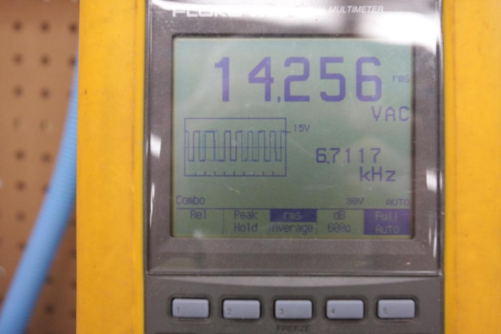
3 DCC Control Voltage on the track is a AC square wave. It is both the power and signal. Decoder in the locomotive reads the track signal and determines the power and polarity the motor is to receive. The polarity of the signal can change while the train is in a section, with no change in speed or direction. All equipment on the layouts sees the same signal. Each decoder determines which commands are for it, based on its programmed address.
4
5 DC vs. DCC With DC you are really controlling the track section. Someone or something (computer) must switch the power to the track sections when multiple trains are being run on a layout. Control is more like a tower man. With DCC you are control the locomotive directly, so control is more like a locomotive engineer.
6 DCC Advantages to Layout Design Because locomotive control is based on a signal and not the control of a track section, it can simplify some layout control functions. Eliminate or reduce the number of switches needed to control a layout. DCC can be used to independently control lights, etc. in rolling stock other than locomotives. DCC accessory decoders can be used to control fixed layout equipment such as turnouts, building lights, etc. NOTE: Accessory addresses are separate from mobile decoder addresses.
7 DCC Advantages to Layout Design Independent control of multiple switch locomotives in a yard. Simplified wiring of engine terminals and locomotive ready tracks. Helper operations. Can run helpers independently. With sound decoders, can communicate with whistle signals. Can rescue stalled trains with a helper. With DCC controlled couplers, can uncouple while moving.
8 DCC Advantages to Layout Design Can greatly simplify the control of complicated track work. NOTE: Detection sections are still needed for signaling/interlocking purposes.
9
10 DCC System Parts Cab (Throttle) Device used to control the layout, including locomotive speed and directions, sound functions, turnouts, etc. Cab Bus Used to connect cabs to system. May support radio or infra-red communication. Usually manufacturer specific (NCE Cab Bus, Digitrax LocoNet, Lenz XpressNET, etc.)
11 DCC System Parts (Continued) Command Station The heart of the DCC system. Takes the inputs from the cabs on the cab bus and generates the DCC signal. Control Bus Used to connect the command station to the boosters (power stations). Booster (Power Station) Takes the DCC signal from the Control Bus, amplifies it, and provides a signal to the track with enough magnitude to power DCC devices on the layout. Usually also includes short circuit protection for the section it powers.
12 DCC System Parts (Continued) Track Signal What is really covered in the NMRA Standards. Decoder The DCC component installed to control the layout device. Can include: Mobile decoders with or without sound functions for locomotive control. Function only decoders to control lights, etc. in rolling stock. Accessory decoders to control turnouts, signals, layout lighting, etc.
13 DCC Layout Parts (Continued) Note that the above parts are the logical components of a DCC system and several parts may be grouped together. Command stations and power stations are commonly grouped. All-in-one systems also can include the cab with the command and power stations.
14 Layout Wiring Layout wiring is simple, just run two wires around, except: You still must take into account reversing sections. A short anyplace (such as a train being run against a switch thrown the wrong way), shuts down the whole railroad. You still need to sectionalize wiring if you need detection for signaling or an interlocking. Your wiring must be of sufficient capacity for short circuit detection to work. You may want to sectionalize your layout just for trouble shooting.
15 Wiring Capacity Wiring Capacity Wire size must be capable of carrying the load current available. Boosters are 5 or 10 amps vs. DC power packs, which may only be 1 amp. Wire size must not limit the current that flows during a short circuit to prevent the short circuit system from operating. Test for adequate wiring A short at any track location, should operate the short circuit protection. Commonly referred to as the quarter test by HO modelers. In S scale we need to use something bigger. A piece of metal placed on the track should operate the short circuit protection.
16 Recommended Wiring Sizes Bus Wire Size 10% 5 A 5% 5 A 10% 10 A 5% 10 A 18 AWG AWG AWG AWG AWG
17 Recommended Wiring Sizes Wire lengths shown in the recommended chart are the run length from the booster to track. Actual wire needed is twice that. You can run wires in more than one direction from a booster to cut down on the length. In the American Wire Gauge (AWG), smaller numbers correspond to larger wire. Recommended track feeder size is 18 AWG to 22 AWG and length should be kept under 18 inches. Recommended that there be no more than 6 between feeders.
18 Layout Sectioning Larger layouts May need to be divided into sections so a short in one section does not shut down the entire railroad. You may want to do this just for trouble shooting purposes. DCC Circuit Breakers Devices made to detect a short circuit and interrupt it before the booster short circuit protection operates. Must coordinate with booster short circuit protection. Does not provide any more capacity.
19 Layout Sectioning Continued Booster Additional boosters can be used in sections. Most expensive way Provides more system capacity. Switches Does not help short circuit protection, but does provide trouble shooting isolation. Makes an easy point to add a future DCC circuit breaker or another booster without having to modify the track wiring.
20 Booster Capacity How many boosters do you need? Add up all the loads that operate at one time. Locomotives (running, idle, with sound, with smoke) Rolling stock lighting Accessory decoder operated equipment powered from the DCC system. Boosters come in 5, 8, and 10 amp sizes. If you need multiple boosters, you have to decide how to split them up. Mainline, large yard, engine terminal, switching district, branchline, etc.
21 What I Do On My Layout I have one 10 amp booster. (I probably don t need that much, but that s what I have.) I ran a #12 AWG main DCC bus around the layout. I installed a switch for each town or area I want to sectionalize. Right now I m just in the track laying stage, so I don t have multiple people operating. Allows me to easily replace the switch with a circuit breaker, etc. in the future without doing any track rewiring. Did it on my old layout and hardly used it, so it worked OK for me.
22 What I Do On My Layout (Continued) From each sectionalizing switch, I run a #14 AWG sub-bus through out an area (usually a town). When I need to end a bus, I terminate it on a terminal block. I run #22 AWG feeder drops from the track to the bus. If the distance is too long I insert a piece of #18 AWG wire between the sub-bus and the #22 drop. I use #22 for my drops because I use small rail. My largest rail is Code 83 and most of is or will be Code 70 and 55. The smaller wire size works better with the smaller rail. I run a feeder from every piece of rail to the bus. I don t use rail joiners except for switch point hinges, so I don t really have a choice. I hand lay track so I am mostly working with 3 pieces of rail. I use a resistance soldering unit to solder the drop wires on the rails. I can hold the wire against the rail with the soldering tweezers.
23 What I Do On My Layout (Continued) I use solid wire for the #22 drops and stranded for the buses. I find stranded easier for me to use, but it does not matter for our purposes. To feed movable sections, where the wire flexes, stranded wire is better, and the more strands for the same size, the better. I have some more flexible wire that I use for this purpose. I use the Scotch suitcase connectors to connect the feeders to the sub-bus. They work reliably for me. If you choose to use them, you must use them only for the wire sizes and types (solid or stranded) that the particular model is rated. I also happen to have the Scotch crimping tool, but I have a lot of connections to do. (I ve done several hundred so far.) I don t solder under the layout. I use either the suitcase connectors or terminal blocks for connections under the layout.
24 Reversing Sections Three general types: Reversing loops Wyes Turntables Since we are using DCC, we don t need to worry about the polarity of the track under the train, but we still need to make sure the polarity of the track is consistent. This means we can switch the polarity under the train to make the track match.
25 Reversing Loops When using DC, we had to a have a switch for the mainline polarity, plus one for the reversing loop polarity. With DCC we still need to switch the polarity of the reversing section. There is no need to switch the polarity of the mainline. Switching the polarity of the reversing section with a switch or relay contacts still works. Reversers designed for DCC that operate automatically are available. They can be used to power the reversing section. They must coordinate with the booster short circuit protection. A reversing booster can also be used, but is more expensive.
26 Wyes With a wye, either a leg of a wye or a tail can be the reversing section. If the wye has a tail that does not connect to any other part of the wye, it can be used as the reversing section. Either contacts that work with the turnout position or a DCC automatic reverser can be used. If a leg of the wye is the reversing section, the polarity can be switched with a switch or a DCC automatic reverser. The leg of the wye that is the reversing section must be of sufficient length to hold the entire train.
27 Turntables In a turntable, the table itself is the reversing section. Traditional methods such as split ring still work fine. A DCC reversing device can also be used.
28 Questions?
DCC Basics for MRR layouts By Elmer McKay
 DCC Basics for MRR layouts By Elmer McKay Part 3 Track Wiring Main Power Bus Power to run our model locomotives has to be put on the rails or track from the Command Station or Booster. We use wires to
AC-DC-DCC. AC-DC-DCC4_blue.ppt x 8/1/2012 Slide 1
 AC-DC-DCC4_blue.ppt x 8/1/2012 Slide 1 NOTE This Clinic Is Highly Animated With Picture Overlays And Graphics. PDF and Other Versions May Look Contaminated. AC-DC-DCC4_blue.ppt x 8/1/2012 Slide 2 AC-DC-DCC
NanoX v Introduction. NanoX is a simple DCC command station, without pretensions, that includes XpressNet bus v.
 NanoX v.2 1.- Introduction NanoX is a simple DCC command station, without pretensions, that includes XpressNet bus v.3 and can control: - 16 locomotives simultaneously in the addresses 1 to 9999-1024 turnouts
TEAM DIGITAL. SC82 Servo Controller
 TEAM DIGITAL SC Servo Controller Improving the world of DCC > DCC compatible accessory decoder > Control servos motors > Output status LEDs > inputs for turnout control > 6 inputs for semaphore signaling
AUTOMATIC FROG JUICER FROGmini
 AUTOMATIC FROG JUICER FROGmini Automatically Switches the Frog Polarity on DCC Layouts Supplies power to the frog section of a set of points Automatically corrects the frog polarity for the route selected
An overview of DCC Terminology
 An overview of DCC Terminology This page already seems to go on forever and it is clearly a never ending project! We have started with a general set of definitions and will hopefully expand it as time
T-TRAK PowerPole Bus Wires
 Glenn McLain & Steve Jackson, NVNTRAK T-TRAK Division Overview These Bus wires (feeders) are based on the NTRAK PowerPole RP. For additional information see the PowerPole information at www.ntrak.org or
TEAM DIGITAL. Servette TM Single Servo Controller
 12 7 Summary of Configuration Variables CV# Function/Default Value CV# Function/Default Value 1 Servo Address 1 43 reserved - 2 reserved - 44 Sec Input Control 26 3 Servo Move Range 15 45 reserved - 4
TEAM DIGITAL. SMC4 Servo & Motor Controller
 16 CV# Function/Default Value CV# Function/Default Value 28 reserved - 73 Servo 3 Behavior 0 29 Decoder Configuration 0 74 Servo 4 Behavior 0 30 reserved - 75 Output Flash 0 31 Ops Mode Loco Address 1
N12SR Decoder. $29.95 Decoder version 3.3 Dimensions: 0.34 x 0.70 x.12 inches x 18 x 3.2 mm
 N12SR Decoder $29.95 Decoder version 3.3 Dimensions: 0.34 x 0.70 x.12 inches - 8.6 x 18 x 3.2 mm This is an EPF (extended packet format) decoder supporting: Silent Running TM motor drive eliminates annoying
POWER PRO Digital Command Control
 Technical Reference for the TM POWER PRO Digital Command Control D13SR Decoder Dimensions: 1.65 x 0.630 x.120 inches 42 x 16.5 x 3.2 mm Decoder version 3.2 $29.95 This is an EPF (extended packet format)
Signalist SC2. DCC servo point controller user manual
 Signalist SC2 DCC servo point controller user manual 1 Contents Signalist SC2 user manual... 3 Overview... 3 Connections... 3 Power connection... 4 Accessory bus connection... 5 Track connection... 6 Frog
Basic Electronics for Model Railroaders By Gene Jameson NMRA Convention, Kansas City MO., August 5 12, 2018
 Basic Electronics for Model Railroaders By Gene Jameson NMRA Convention, Kansas City MO., August 5 12, 2018 Please turn off your cell phones. If it rings I will ask you to leave the room and I will NOT
Making Your Railroad Real Infrared Detector/Signal Driver For Crossing Signals CFD-IF (V3)
") Making Your Railroad Real www.sbsignal.com Infrared Detector/Signal Driver For Crossing Signals CFD-IF (V3) CFD-IF Manual 2010 Table of Contents Description Page CDF-IF Description and Materials needed
Making Your Railroad Real www.sbsignal.com Infrared Detector/Signal Driver For Crossing Signals CFD-IF (V3) CFD-IF Manual 2010 Table of Contents Description Page CDF-IF Description and Materials needed
NIMFT-B Decoder $ Plug and play decoder for Intermountain FT-B units
 NIMFT-B Decoder Plug and play decoder for Intermountain FT-B units $29.95 This is an EPF (extended packet format) decoder supporting: Silent Running TM motor drive eliminates annoying motor hum or buzz
28 mm. 18 mm. 14 mm. 10 mm Length to fit. 7 mm. 16 mm. 7.5 mm. 18 mm 10 mm 25 mm. 3 mm.032 Brass. Wire. Figure 1: Ground Throw Components
 Modified Slanser Ground Throw Switchstand Bill Johnson of the Sunrise Division of the NMRA has demonstrated and documented the Slanser Ground Throw mechanism on several occasions. His design requires the
POWER PRO. Digital Command Control. D14SRP Decoder. Decoder version 3.2 $29.95
 Technical Reference for the TM POWER PRO Digital Command Control D4SRP Decoder Dimensions:.8 x.65 inches 27 x 6.5 mm Decoder version 3.2 $29.95 This decoder is designed specifically to fit decoders with
GCX GRADE CROSSING EXPANDER
 GCX GRADE CROSSING EXPANDER By The Solution W. S. Ataras Engineering, Inc. PO Box 25 West Terre Haute, IN 47885 Rev. B, 3/31/2003 Copyright 1998, 2003 W. S. Ataras Engineering, Inc. All Rights Reserved
User guide. Revision 1 January MegaPoints Controllers
 MegaPoints Servo 4R Controller A flexible and modular device for controlling model railway points and semaphore signals using inexpensive R/C servos and relays. User guide Revision 1 January 2018 MegaPoints
Power wire and the big three upgrade and why it s important.
 Power wire and the big three upgrade and why it s important. We all know that it takes wires to make electronics work. But what it the reason there are different sizes of wires? Does it make any difference?
Methods of Turnout Control. By Barry Rosier and Mike Dettinger
 By Barry Rosier and Mike Dettinger Manual Slide Switches Ground Throws BullFrog Bluepoint Slide Switches Ground Throws BullFrog Only requires 2 of vertical clearance Sidewinder Horizontal Mount requires
Contents. Warranty and Disclaimer 2 Introduction 3
 Contents Warranty and Disclaimer 2 Introduction 3 Physical Dimensions Board Layout 4 Usage Using the Relay board 5 Setting the start address 5 Configuration Jumper 6 Using the Relays 7 Using the DMX connectors
POWERHOUSE Digital Command Control
 Technical Reference TM POWERHOUSE Digital Command Control SW9-SR Drop-In Decoder Dimensions:.95 x.83 x.2 inches 5 x 2 x 3. mm Version 3.2 $29.95 This decoder is designed for easy installation in Lifelike
Micro Engineering & BK Enterprises Turnouts
 Micro Engineering & BK Enterprises Turnouts MICRO ENG. BK ENTERPRISES MICRO ENGINEERING - NEW STYLE News Flash! Micro Engineering has announced DCC Friendly (Compatible) turnouts! Code 70, 83 #6 only Micro
An Arduino-based DCC Accessory Decoder for Model Railroad Turnouts. Eric Thorstenson 11/1/17
 An Arduino-based DCC Accessory Decoder for Model Railroad Turnouts Eric Thorstenson 11/1/17 Introduction Earlier this year, I decided to develop an Arduino-based DCC accessory decoder for model railroad
Train Detection. And Simple Signaling. By Scott Russell 01/11/14
 Train Detection And Simple Signaling By Scott Russell 01/11/14 Simplest Train Detection Train John I see there is a train in that block Turnout Position Indication Detection: Need to know which way the
Tsunami Digital Sound Decoder. Quick Start Guide for the Blackstone Models C-19
 Tsunami Digital Sound Decoder Quick Start Guide for the Blackstone Models C-19 May 2011 Notice The information in this document is subject to change without notice. Neither Blackstone Models or SoundTraxx
POWER PRO. Digital Command Control. DA-SR Decoder. Decoder version 3..2 $29.95
 Technical Reference for the TM POWER PRO Digital Command Control DA-SR Decoder Dimensions: 2.85 x.66 x.2 inches 72 x 7 x 3.2 mm Decoder version 3..2 $29.95 Atlas GP38, GP, RS/2/3, C2/5, GP7, RSD/5/2, C3-7,
Powerpole General Assembly Instructions
 Powerpole General Assembly Instructions The contacts go in the housings in only one way. Insert the contacts with their sharp edge down against the flat spring that is in the housing. They should slide
TRAINS, CARS AND DRONES
 Gamesontrack TRAINS, CARS AND DRONES WITH RADIO AND INDOOR GPS Automate your layout quicker, and easier with no complex wiring, and let the GPS draw your layout plan. www.gamesontrack.co.uk gamesontrack
GCC GRADE CROSSING CONTROLLER
 GCC GRADE CROSSING CONTROLLER By The Signaling Solution, Inc. PO Box 37 Shelburn, IN 47879 Rev. D, 11/27/2010 Copyright 1998, 2003, 2009 The Signaling Solution, Inc. All Rights Reserved TABLE OF CONTENTS
SwitchPilot. User manual Third edition, October SwitchPilot SwitchPilot Extension SwitchPilot Servo P/N
 User manual Third edition, October 2008 51800 51801 Extension 51802 Servo P/N 04708-07029 1 2 Contents 1. Declaration of conformity... 3 2. WEEE declaration... 3 3. Important notes Please read this chapter
Layout Planning. Education Program Basic Skills Series Module Three
 Education Program Basic Skills Series Module Three Layout Planning The following pages introduce the essential elements of planning for your model railway What do I want to model? Practical considerations
ENVIRONMENTAL. Operating Temperature: -40ºC to +130ºC. Wire Size. Code Accepted Max Wire Gauge Insulation AWG Solid or Stranded
 Wire-to-Wire (WTW) connectors have been used in the industrial market for years with traditional 2-Piece (plug & socket) connector systems. These require crimp and poke wire terminations to connect discrete
MegaPoints Servo Controller
 MegaPoints Servo Controller Covers Servo Controller boards 1.8 onwards A flexible and modular device for controlling model railway points and semaphore signals using inexpensive R/C servos and relays.
One line and Three line diagrams Schematics Wiring Diagrams Logic ladders Ancillary prints Pictorial instructions
 One line and Three line diagrams Schematics Wiring Diagrams Logic ladders Ancillary prints Pictorial instructions One line diagram (1) One line diagrams will typically show in a simple fashion an over
PLANNING YOUR SYSTEM
 INTRODUCTION HERTIAGE amplifiers provide high-performance sound reinforcement for your mobile audio equipment. Its versatility enables compatibility with optional Equalizers, Frequency Dividing Crossover
 Train Tech overview - ask for free catalogue Signal kits - OO/HO low cost easy to make signals for DC Sensor Signals - easy automatic block signalling - DCC or DC Smart Lights - small effects built in
Figure 1. DMC 60 components.
 1300 Henley Court Pullman, WA 99163 509.334.6306 www.digilentinc.com DMC 60 Reference Manual Revised November 15, 2016 This manual applies to the DMC 60 rev. A Overview The DMC 60 is an electronic speed
Operation and Installation Manual
 The Next Generation of Operation and Installation Manual G-Scale Graphics 5860 Crooked Stick Dr. Windsor, CO 80550 970-581-3567 GScaleGraphics@comcast.net www.gscalegraphics.net Revision C: H: Updated
Hand-Laying Turn-outs. By Brad Morneau
 Hand-Laying Turn-outs By Brad Morneau 1 Index Section: Page(s) Introduction 3 Turnout basics 3 Fast-Track Templates 4 First Step: Plot the turnout 5 Drilling pilot holes 5 Lining up the Switch Machine
POWERPOLE CONNECTORS. Fountain Valley RACES 05 Feb 2008
 POWERPOLE CONNECTORS Fountain Valley RACES 05 Feb 2008 ACCESORIES SPLITTER WITH OEM T-CONNECTOR ACCESSORIES RED DEE 2 SPLITTER Any connection point is an input / any connection point is an outlet ACCESSORIES
Contents. Warranty and Disclaimer 2 Introduction 3
 Contents Warranty and Disclaimer 2 Introduction 3 Physical Dimensions Board Layout 4 Servo connections 5 Using the Serv8 Usage 6 Setting the start address 7 Setting the pulse width 8 Using the configuration
LocoBooster HDM05 Liability disclaimer:
 LocoBooster HDM05 Liability disclaimer: Use all items that can be bought and installation instructions that can be found on this site at your own risk. They have been developed for personal use, and I
TAM VALLEY DEPOT. Quad-LN User Manual. Gen2 Firmware v1.1
 TAM VALLEY DEPOT Quad-LN User Manual Gen2 Firmware v1.1 N3IX Engineering 20 Aug 2013 Contents 1 Basics... 1 1.1 Overview... 1 1.2 Servos... 1 1.3 External Power Supply... 1 1.4 Onboard LED Indicators...
ANDERSON POWERPOLE CONNECTORS FOR HAM OPERATORS
 ANDERSON POWERPOLE CONNECTORS FOR HAM OPERATORS The Anderson Powerpole connector is a very good connector to sharing connections between users for such things as batteries, radios, chargers and other DC
LocoRCD2 Manual. HDM20C For scale Z, N, TT and HO. HDM20E For scale O, 1 and G
 LocoRCD2 Manual HDM20C For scale Z, N, TT and HO HDM20E For scale O, 1 and G Liability disclaimer: Use all items that can be bought and installation instructions that can be found on this site at your
9 Feedback and Control
 9 Feedback and Control Due date: Tuesday, October 20 (midnight) Reading: none An important application of analog electronics, particularly in physics research, is the servomechanical control system. Here
RAILROADER S HANDBOOK
 RAILROADER S C/MRI APPLICATIONS HANDBOOK Volume 1 System Extensions Version 3.0(1) By Dr. Bruce A. Chubb, MMR Chapter 3: OD TRACK OCCUPANCY DETECTOR www.jlcenterprises.net 2014 Bruce A. Chubb Chapter 3
MegaPoints Controller
 MegaPoints Controller A flexible solution and modular component for controlling model railway points and semaphore signals using inexpensive servos. User guide Revision 10c March 2015 MegaPoints Controllers
Contents. Warranty and Disclaimer 2
 Contents Warranty and Disclaimer 2 Physical Dimensions Board Layout 3 Usage Using the PWM board 4 Setting the start address 4 Dimming LED s 5,6 Typical hookup 7 Terminator 8 Troubleshooting Ground, termination,
************* OWNER'S MANUAL STAX1250/2 STAX1800/2 STAX2200/2 STAX1200/4 STAX1600/4 STAX2300/4 STAX2000/1D STAX4000/1D STAX5500/1D
 ************* OWNER'S MANUAL STAX1250/2 STAX1800/2 STAX2200/2 STAX1200/4 STAX1600/4 STAX2300/4 STAX2000/1D STAX4000/1D STAX5500/1D INTRODUCTION Power Acoustik amplifiers provide high-performance sound
TrainSpeed 4. Four separate train speed indicators. Model Railroad Speedometer Operating Manual
 TrainSpeed 4 Four separate train speed indicators Model Railroad Speedometer Operating Manual TCS Inc. 215-453-9145 Main Number 215-257-0735 Tech Number www.tcsdcc.com SKU: 1548 TrainSpeed Operating Instructions
Model Railroad Calculator Tools Manual
 Model Railroad Calculator Tools Manual Version: 1-2-0-0 Date: 29 August 2015 Mail: info@vansoft.co.za WEB: http://www.vansoft.co.za Table of Contents 1 Introduction...1 1.1 Main Screen Menu Options...1
LM675 Power Operational Amplifier
 Power Operational Amplifier General Description The LM675 is a monolithic power operational amplifier featuring wide bandwidth and low input offset voltage, making it equally suitable for AC and DC applications.
When input, output and feedback voltages are all symmetric bipolar signals with respect to ground, no biasing is required.
 1 When input, output and feedback voltages are all symmetric bipolar signals with respect to ground, no biasing is required. More frequently, one of the items in this slide will be the case and biasing
The Allen-Bradley Servo Interface Module (Cat. No SF1) when used with the Micro Controller (Cat. No UC1) can control single axis
 when used with the Micro Controller (Cat. No UC1) can control single axis") Table of Contents The Allen-Bradley Servo Interface Module (Cat. No. 1771-SF1) when used with the Micro Controller (Cat. No. 1771-UC1) can control single axis positioning systems such as found in machine
Table of Contents The Allen-Bradley Servo Interface Module (Cat. No. 1771-SF1) when used with the Micro Controller (Cat. No. 1771-UC1) can control single axis positioning systems such as found in machine
ENVIRONMENTAL. Operating Temperature: -40ºC to +125ºC. Wire Gauge Size
 The 917X series of surface mount Insulation Displacement Connectors (IDC) were developed to meet the harsh automotive and industrial market applications for connecting individual wires directly to a PCB
Understanding the 302 point motor.
 PAGE 1 Understanding the 302 point motor. All of our point motors are fully tested before posting to you, and we thank you for your order and wish you many years of happy operation. Our helpline is open
ECE 5670/6670 Project. Brushless DC Motor Control with 6-Step Commutation. Objectives
 ECE 5670/6670 Project Brushless DC Motor Control with 6-Step Commutation Objectives The objective of the project is to build a circuit for 6-step commutation of a brushless DC motor and to implement control
Test Procedure for Nanometric Discriminator Cards for Wire Chambers. James Clarke
 Test Procedure for Nanometric Discriminator Cards for Wire Chambers James Clarke November 26, 2013 To test a discriminator card, first ensure you have the proper equipment. For our setup, we had three
HOW TO PROPERLY BUILD AN IN-BUILDING DAS SYSTEM Part 1 Use of Directional Couplers in DAS By J. Macias
 HOW TO PROPERLY BUILD AN IN-BUILDING DAS SYSTEM Part 1 Use of Directional Couplers in DAS By J. Macias RF in-building coverage has become a fast growing market in recent years. Commercial wireless users
Com-Trol ADV-6000 Trouble Shooting Guide Click on red text to go to that page in guide
 Com-Trol ADV-6000 Trouble Shooting Guide Click on red text to go to that page in guide Topic Introduction 1 Tool Requirements 1 Trouble Shooting Check List 1 Page(s) Lost communications to controller(s)
poly-planar ME-51 Subwoofer Amplifier Waterproof Marine Audio
 ME-51 Subwoofer Amplifier 1 ME-51 Subwoofer Amplifier Introduction: The ME-51 is a dual channel mono audio amplifier capable of delivering 50W RMS (100W total music power). It is designed to be used with
COPALUM Terminals and Splices (For Solid & Stranded Aluminum or Copper Wire)
") Product Facts Bar Crimp Technique Terminals and Splices for aluminum-to-aluminum and aluminum-to-copper stripped wire applications Terminates stripped, stranded and solid (round or rectangular) aluminum
Product Facts Bar Crimp Technique Terminals and Splices for aluminum-to-aluminum and aluminum-to-copper stripped wire applications Terminates stripped, stranded and solid (round or rectangular) aluminum
Standard AWG: WTB
 The 917X series of surface mount Insulation Displacement Connectors (IDC) were developed to meet the harsh automotive and industrial market applications for connecting individual wires directly to a PCB
WARNING! Remove power to the pinsetter by turning off the circuit breaker and unplugging the main power cord to the electrical box.
 A & A-2 Plug-In Motor Start Relay 12-862203-000 Packaging (1) 12-862203-000 Plug-In Motor Start Relay Package, contains: (1) 11-696644-000 Relay (1) 11-696645-000 Relay Base (2) 11-696684-000 Relay Clips
Exercise 10. Linear Slides EXERCISE OBJECTIVE
 Exercise 10 Linear Slides EXERCISE OBJECTIVE In this exercise, you will learn to use a linear slide. You will learn how to use the Linear Slide, Model 5209, to extend the work envelope of the Servo Robot.
TrainSpeed1. Single train speed indicator. Model Railroad Speedometer Operating Manual
 TrainSpeed1 Single train speed indicator Model Railroad Speedometer Operating Manual TCS Inc. 215-453-9145 Main Number 215-257-0735 Tech Number www.tcsdcc.com SKU: 1547 TrainSpeed Operating Instructions
DesignCon Noise Injection for Design Analysis and Debugging
 DesignCon 2009 Noise Injection for Design Analysis and Debugging Douglas C. Smith, D. C. Smith Consultants [Email: doug@dsmith.org, Tel: 408-356-4186] Copyright! 2009 Abstract Troubleshooting PCB and system
LEGO 9V TRAIN TRACK GEOMETRY
 LEGO 9V TRAIN TRACK GEOMETRY by Donát Raáb Brickshelf member of MLVK and Kockajáték Klub Table of contents 1. Getting started...2 What's the point?...2 Standard track pieces...2 2. Basic Rules...3 3. Beyond
LM675 Power Operational Amplifier
 LM675 Power Operational Amplifier General Description The LM675 is a monolithic power operational amplifier featuring wide bandwidth and low input offset voltage, making it equally suitable for AC and
FIRST Robotics Control System
 2018/2019 FIRST Robotics Control System Team 236 1 (click on a component to go to its slide) 2 The Robot Powered solely by 12V battery RoboRIO- is the computer on the robot Controlled by Java code on the
GUIDE TO TROUBLESHOOTING INFRA RED SYSTEMS
 GUIDE TO TROUBLESHOOTING INFRA RED SYSTEMS Infra-red systems offer very high reliability of detecting rolling stock passing over the sensor. If you are having problems with triggering of the system, this
To be a Digital-Professional! Digital driving and switching of dual-coil drives with DiCoStation, DigitalBooster DB-4 and 2-rails conductor
 LD Digital-Compendium (-DC-002_10_en) o be a Digital-Professional! Digital driving and switching of dual-coil drives with, and 2-rails conductor he main focus of this chapter shall cover the simple installation
Device Interconnection
 Device Interconnection An important, if less than glamorous, aspect of audio signal handling is the connection of one device to another. Of course, a primary concern is the matching of signal levels and
Circuit Breakers. Excerpt from Master Catalogue. Circuit Breakers. Specifically For You
 Circuit Breakers Excerpt from Master Catalogue Circuit Breakers Specifically For You Hydraulic-magnetic technology ensures reduced nuisance tripping with temperature variance Always holds 00% rated current
Transmitter User Guide
 Transmitter User Guide Table of Contents Introduction...4 1 Getting Started...5 1.1 Overview... 5 1.2 Display... 6 1.3 Quick Start... 7 1.3.1 Setup... 7 1.3.2 Wake System... 7 1.3.3 Binding Receiver to
Using the S.BUS interface
 Using the S.BUS interface One of the benefits of using FrSky is that the X8R receiver comes with an S.BUS socket. This is an abbreviation of Serial Bus. S.BUS enables you to have one wire feeding an area
Unit 3: Introduction to Op- amps and Diodes
 Unit 3: Introduction to Op- amps and Diodes Differential gain Operational amplifiers are powerful building blocks conceptually simple, easy to use, versatile, and inexpensive. A great deal of analog electronic
TAM VALLEY DEPOT. QuadLN_S User Manual
 TAM VALLEY DEPOT QuadLN_S User Manual Firmware v1.0 N3IX Engineering 25 August 2014 N3IX Engineering 2014 Contents 1 Basics... 1 1.1 Overview... 1 1.2 Servos... 2 1.3 External Power Supply... 2 1.4 Onboard
Operating Temperature: -40ºC to +125ºC 6XX. Wire Gauge Size
 AVX developed the initial SMT discrete wire IDC connector 5 years ago for 26-28AWG AVX wires. Since then, we have seen this Wire-to-Board (WTB) contact technology spread to multiple wire gauges and multiple
Advanced Paralleling of LTC Transformers by VAR TM Method
 TAPCHANGER CONTROLS Application Note #24 Advanced Paralleling of LTC Transformers by VAR TM Method 1.0 ABSTRACT Beckwith Electric Company Application Note #11, Introduction of Paralleling of LTC Transformers
Turnout control redefined
 Page 1 About these pages... We ve done our best to make this far more than just an owners manual We thought we would start by telling you a bit more about what is included in these pages... as while they
Protection Basics Presented by John S. Levine, P.E. Levine Lectronics and Lectric, Inc GE Consumer & Industrial Multilin
 Protection Basics Presented by John S. Levine, P.E. Levine Lectronics and Lectric, Inc. 770 565-1556 John@L-3.com 1 Protection Fundamentals By John Levine 2 Introductions Tools Outline Enervista Launchpad
RailLinx 900 Control System. Operation Manual
 RailLinx 900 Control System Operation Manual RCS America RailLinx 900 Control System Operation Manual This manual was written by RCS America Any questions, please don t hesitate to call. RCS America 2818
Golf Trolley Workshop (Devon)
") Golf Trolley Workshop (Devon) Powerpole General Assembly Instructions Assemble the red and black plastic housings together correctly on the first try, they fit snugly and can be difficult to get apart.
Golf Trolley Workshop (Devon) Powerpole General Assembly Instructions Assemble the red and black plastic housings together correctly on the first try, they fit snugly and can be difficult to get apart.
Installation Guide for 10 inch Davies Craig fan in SW20 Engine Lid.
 Installation Guide for 10 inch Davies Craig fan in SW20 Engine Lid. This manual is designed to guide you in installing a Davies Craig thermo fan in the lid of your MR2 to aid in reducing engine and intake
Ansaldo STS USA (Formerly known as Union Switch & Signal)
") Wayside Signaling Systems Ansaldo STS USA AF-902/AF-904 Generation II Digital ASTS USA s AF-902/AF-904 Generation II (AF- Gen II) Series Digital systems provide unmatched capabilities for train detection
Wayside Signaling Systems Ansaldo STS USA AF-902/AF-904 Generation II Digital ASTS USA s AF-902/AF-904 Generation II (AF- Gen II) Series Digital systems provide unmatched capabilities for train detection
Table of Contents. Proximity Sensors. IEC Limit Switches. Encoders. Current Sensors. Section 17
 Proximity Section 17 Table of Contents............ 21 2 Application Guide........................ 21 3 ACT Series Transducers......... 21 4 ACTR Series Transducers........ 21 6 ACS150 Series Switches..................
No Fail Tortoise Installation Instructions
 No Fail Tortoise Installation Instructions The Tortoise switch motor is popular among modelers because it is sturdy, reliable, and operates in a slow, prototypical fashion. You can watch your turnout point
INTELLIMETER REGISTER
 INTELLIMETER REGISTER MODEL RG2 INSTALLATION AND CONNECTIONS INSTALLATION MANUAL WARNING: Any work on or near energized metering equipment can present a danger of electrical shock. All work on these products
Antenna Disconnect THE INEXPENSIVE WAY TO PROTECT YOUR VALUABLE RADIO FROM LIGHTNING SURGES
 Antenna Disconnect THE INEXPENSIVE WAY TO PROTECT YOUR VALUABLE RADIO FROM LIGHTNING SURGES -------------------------------------------------------------------------------------- Operating Manual May 2017
INSTRUCTION BOOK EASILY REMOVEABLE DIES FOR YOUR BINDING NEEDS OD 4012 SHOWN WITH THE OPTIONAL PALM SWITCH FOR THE OD 4012
 RHIN- -TUFF INSTRUCTION BOOK FOR THE OD 4012 AND INTRODUCTION TO THE OD 4012 BINDING MODULES www.rhin-o-tuff.com HD 4270 OD 4300 HD 4470 HD 4171 HD 8370 PAL 14 HD 4170 PAL 14 EASILY REMOVEABLE DIES FOR
In Bloom Beret and Cap
 In Bloom Beret and Cap By: Brittney Waterhouse Materials: Approximately 160-200 yards of a worsted weight yarn Size J hook Buttons to embellish the band-optional Gauge: 12 sc = 4 Diameter of 2 Rows of
FlagShip. Installation Guide / User Manual Effective: January 1 st, Table of contents. 1. FlagShip Preconfiguration
 FlagShip Installation Guide / User Manual Effective: January 1 st, 2016 Please go to our website for the most current version of the FlagShip Installation and Instruction Manual at www.schaller-electronic.com,
Substation: From the Outside Looking In.
 1 Substation: From the Outside Looking In. Moderator n Ron Spataro AVO Training Institute Marketing Manager 2 Q&A n Send us your questions and comments during the presentation 3 Today s Presenter n Greg
Universal Control For Motorola Systems with Brake module
 Universal Control For Motorola Systems with Brake module Technical Operating Manual The basis of this technical operations manual is the description of simple control operations which the device affords.
Keep the Noise Down In There! Designing a Layout to Limit High Speed Rolling Noise.
 Keep the Noise Down In There! Designing a Layout to Limit High Speed Rolling Noise. By David Baillie Introduction Have you ever been put off by the sound of a fast model train running on a layout that
TECHNICAL DATASHEET #TDAX A DC MOTOR CONTROLLER P/N: AX Variable Speed Control, Onboard I/O CAN SAE J1939, Rugged Packaging
 TECHNICAL DATASHEET #TDAX102000 35A DC MOTOR CONTROLLER P/N: AX102000 Variable Speed Control, Onboard I/O CAN SAE J1939, Rugged Packaging with Electronic Assistant Features: Unidirectional or bi-directional