ET2000e IRRIGATION CONTROLLER
|
|
|
- Eleanore Gallagher
- 6 years ago
- Views:
Transcription
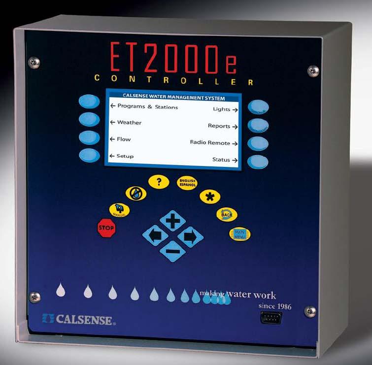
1 ET2000e IRRIGATION CONTROLLER SPECIFICATION ET2000e IRRIGATION CONTROLLER SPECIFICATION
2 ET2000e IRRIGATION CONTROLLER SPECIFICATION CONTROLLER SPECIFICATION HOW TO SPECIFY CONTROLLER: Step 1 Controller Model Number, Number of stations desired. The first section of the part number identification process is deciding the model of Calsense irrigation controller that you want to order. The ET2000e portion is listed first, then the amount of stations that you require. Controller Model Number ET2000e PART NUMBER EXAMPLE: ET2000e-48 Step 2 Communications. Number of Stations -8 stations -12 stations -16 stations -24 stations -32 stations -40 stations -48 stations The second step of the part number process is to identify the communications options that you want to utilize on the controller. Currently Calsense offers two (2) Communications options per Irrigation controller. The Choices are as follows: (-R) Phone Modem: This may be a site with a single irrigation controller, or a project where each irrigation controller will have its own phone line. The customer requests a RJ-11 phone jack from the telephone company at the location of each irrigation controller. The irrigation controller is plugged directly into the phone jack. Each Irrigation controller used with its own phone line is specified as a Model R. (-M) Multi-Controller Communications System: This is a location with several irrigation controllers sharing a single phone line, or another type of communication. A phone line with an RJ-11 phone jack supplied by the telephone company, or a particular communications device is installed at the most feasible controller location. All groups of these controllers must have one controller with the Communications option. The other controllers in the group will all be designated as M controllers. This option includes the M interface and cables. All irrigation controllers are hardwired to the communications controller using Paige P-7171-D communications cable in conduit. Restrictions: There can only be up to 31 irrigation controllers on one multi-controller communications system. The maximum total length of all cable on one multi-controller communication system is 5,000 feet. Communication cable is to be direct pull, installed in conduit. Splices are not recommended. If a project has more than 32 irrigation controllers or a cable length of more than 5,000 foot. A second multi-controller communications chain must be set-up. This must include a second communications controller, and communications cable to communicate with the second group of irrigation controllers. (-LR) Local Radio: The Calsense Local Radio system is designed for wireless communications in local areas. A central HUB located at the project site will communicate with controllers in a local area. The system consists of a telephone modem at the central computer, one or more LR-HUB s, and LR controllers. Several HUB s can be combined in a central system. The communication type can be mixed with other communication type controllers, hard wired controller, and phone controllers in the same central system. The Calsense Local Radio system also offers the flexibility of multiple irrigation controllers
3 ET2000e IRRIGATION CONTROLLER SPECIFICATION sharing one Radio Modem. An advantage of using the Local Radio system is there are no monthly fees. Equipment Needed: Central: The central computer uses a telephone modem for the Base Station to communicate to the LR-HUB s. Local Radio communications will work only with Command Center for Windows software. LR-HUB: The LR-HUB is mounted in a standard irrigation controller cabinet. The HUB panel is the same size as a standard controller panel. The HUB contains a radio and a telephone modem. The central computer communicates to the HUB through the telephone modem. The HUB communicates to the LR controllers by Local Radio. The LR-HUB requires an antenna, an LR-STICK (stick antenna) or LR-YAGI (Yagi antenna). Optionally the LR-HUB may be directly connected to the central computer through standard serial cable, or may also be mounted in a Calsense SSE enclosure. -LR: The LR is a controller with a local Radio installed. It is mounted in a standard irrigation controller cabinet. It can also be mounted in the Calsense SSE-R enclosure. The controller requires an antenna, either the LR-DOME dome type antenna, or the LR-YAGI Yagi type antenna. The SSE-R enclosure comes with the LR-DOME antenna installed when specified for use with Local Radio. Note: It is also possible to chain M controllers to the LR controller via Paige cable (see M communications for definition). This combination would be referred to as a MLR. (-SR) Spread Spectrum Radio: The Spread Spectrum Radio option is used when a hardwire link between controllers is not possible. The Spread Spectrum Radio can be thought of as replacing the hardwire link with radios. The Spread Spectrum radio operates in a non-licensed radio frequency band. This radio utilizes a frequency hopping technology to eliminate interference. The SR option would be primarily used on a site where the FLOWSENSE option is used. The SR option may be combined with hardwire link on a site to create a flexible and cost efficient communication network. Equipment Needed: Multiple controllers (Radio Link only): The project site consisting of multiple irrigation controllers. Each of the irrigation controllers is specified as a SR communications option. Each controller requires an antenna, the standard type of antenna used on an enclosure is the dome antenna and is specified as an SR-DOME. The irrigation controllers will be setup to communicate between themselves with the Spread Spectrum radio using unique communication addresses. Multiple controllers (with Hardwire link): The project site will consist of multiple irrigation controllers. One of the controllers will be specified as the master radio with the designation MSR communications option. The controller with the MSR option requires an antenna, the standard type of antenna used on an enclosure is the dome antenna and is specified as a SR-DOME. The other irrigation controllers will be specified with the M communications option. These will be linked to the master radio controller using Paige P-7171-D communications cable in conduit. You may have several controllers on a site communicating with the radio link only along with several other controllers on the same site with a hardwire link. This allows the designer to mix and match the two communications options to provide the most flexible communications network possible. Restrictions: A Radio survey must be conducted by Calsense. There is no-charge for this service. The Radio requires a clear line of site for communications. (-EN) Ethernet communications: The Calsense Ethernet communications option provides reliable data communication links utilizing the customers existing Ethernet network. The option is designed to connect the Calsense ET2000e controller with serial interface to an existing Ethernet. The Ethernet option is typically used where a user has easy access to an existing Ethernet network. Typical projects include a school campus, business campus or a city with buildings that are linked with an Ethernet network.
4 ET2000e IRRIGATION CONTROLLER SPECIFICATION The Computer, when connected to a network and operating the Calsense Command Center software, will access any controller that is connected to the Ethernet network. The Calsense controller is specified with a EN option when one controller is sharing one Ethernet connection. The Ethernet communication option is compatible with the Calsense ET2000e controller. The Calsense Ethernet option is integrated into the controller and does not require a separate power source. This arrangement provides for a small highly dependable package. The user must supply an Ethernet (RJ45) connection at the controller location with the network set to have access to this connection. The Ethernet network must also be set to assign a static IP address to the ET2000e controller. (-GR) GPRS Modem: The GPRS radio delivers reliable, long distance data communication links through the advantage of wireless technology. The Calsense GPRS radio is integrated into the controller and does not require a separate power source. Compact in size, the GPRS fits into the standard Calsense wall mountable enclosure. The GPRS system utilizes Internet Protocol (IP) addressing, assigning a permanent IP address to each modem when activated. Built-in encryption maintains the security of the data transmitted. The system is always on and never requires dial up or delays in connecting. A central computer operating the Calsense Command Center software requires a GPRS host radio for access to the GPRS network. (-FOM) Fiber Optic Modem: The Calsense Fiber Optic Modem communications option provides High-reliability traffic signalization networking. This option is designed to connect the Calsense ET2000e controller with a Fiber Optic Modem to a Fiber Optic Network. Typical Projects include Freeway or highway systems that are linked via Fiber Optic Network. The Computer, when connected to a network and operating the Calsense Command Center software, will access any controller that is connected to the Fiber Optic network. The Calsense controller is specified as a -FOM option when one controller is shearing one Fiber Optic connection. The Fiber Optic communications option is compatible with the Calsense ET2000e controller. The Calsense Fiber Optic option is integrated into the controller and does not require a separate power source. This arrangement provides for a small highly dependable package. COMMUNICATIONS OPTION CHART COMM1 COMM2 DEFINITION -R -M -M -LR -LR Phone Line capability, one phone line one controller Ability to chain controllers together with cable and share the first communications option Local Radio, one Local Radio one controller The user is required to enter into an agreement with a third-party network service provider. The associated monthly fees paid to this provider are the responsibility of the user. These fees are estimated to be about $35.00 per month per field controller. A radio survey is required before final acceptance of GPRS radio as the communication method. Please consult with your service provider for proper coverage. The GPRS option requires the end user to sign a service contract with a third-party network provider. -SR -EN -GR -FOM -SR -EN -GR -FOM Spread Spectrum radio, one Spread Spectrum Radio one controller Ethernet device, one Ethernet device one controller GPRS modem, one GPRS modem one controller Fiber Optic Modem, self healing, single mode.
5 ET2000e IRRIGATION CONTROLLER SPECIFICATION Note: Certain communications option combinations are non-practical these include: -EN-EN -FOM-FOM -GR-FOM -GR-EN PART NUMBER EXAMPLE: ET2000e-48-M-SR Note: The following communications types require an antenna, (-GR), (-LR), (-SR). Note: If no communication option is desired just leave the part number the way it is and move on to step three. Step 3 Options. The Calsense irrigation controller allows you to select a number of options that you can include in the overall design they are as follows: (-F) Multiple Flow Meter Interface: All Models of the Calsense controller can receive up to three separate flow meter inputs on projects consisting of more than one water source for irrigating landscape. The controller will sum up the readings of all flow sensors connected. The irrigation controller is specified as a (-F) controller. The first flow meter is wired to the irrigation controller using the standard Calsense red and black flow meter wires. The second and third flow meters are wired to the irrigation controller using an additional wire harness supplied when a (-F) option is specified. (-G) ET Gage interface: All Models of the Calsense controller can receive the ET Gage interface option. This allows the controller to collect Evapotransperation data via an ET gage. The controller keeps a table of the last 28 days of ET. When it comes time to irrigate a station, the controller adds up the ET numbers since the last irrigation. If it has been 3 days since it irrigated, it will total the first three numbers in the table. If these numbers are.20,.15, and.10, the total would be.45. The controller will multiply this number by the station %of or ET factor to calculate how much water to apply (% of ET factor is used to adjust for irrigation efficiency and crop type). If the % of ET factor is 60%, the controller would multiply.6 times.45 to get.30. Using the precipitation rate stored in the controller, the run time is calculated. If the precipitation rate is 2.00 per hour, the run time will be 15 minutes (1/4 hr. The user can program the cycle and soak feature to divide up the 15 minutes into individual run times. If the cycle time is set to 5 minutes, there will be one start time and two repeats. If there is no signal from the ET Gage, historical data is used as a back-up. (-RB) Rain Bucket interface: The Calsense Irrigation controllers can keep a record of accumulated rainfall when using the Calsense Model RB-1 Rain Bucket. The irrigation controller is specified as a RB controller. The rain bucket consists of a tipping mechanism which measures every 0.01 inches of rainfall, and is used in conjunction with the daily ET mode of the irrigation controller. The Calsense controller receives this information and takes into account the actual amount and rate of rainfall when calculating station run times. The measured water drains out of the bottom of the housing. Therefore the bucket requires no additional service of any kind. It is completely automatic. One rain bucket can be shared by multiple controllers, or Rain Bucket data can be shared by multiple controllers through the Calsense Command Center software. (-WG) Wind Gage interface: The Calsense Irrigation controllers can monitor wind speed using the Calsense Model WG-1 Wind Gage. The irrigation controller is specified as a WG controller. The wind gage sends pulses to the Calsense irrigation controller, which in turn automatically stops irrigation once the wind speed increases above a user set limit. As wind dies down, the Calsense irrigation controller will resume irrigation where it left off. The wind gage cannot share with other controllers through the Calsense Command Center Central System (unless the -FL option is in use with all other controllers in the same chain).
6 ET2000e IRRIGATION CONTROLLER SPECIFICATION (-FL) FLOWSENSE interface: The Calsense FLOWSENSE option is available on the ET2000 and ET2000e Irrigation controllers. This option is used when one or more controllers are sharing one or more Master Valves, Flow Meters, or Pumps. The Calsense FLOWSENSE option is designed to allow the user to setup and operate this feature directly in the field with the Calsense controller. There is no requirement for a central computer to operate this feature. The FLOWSENSE option makes use of innovative technology to cooperatively communicate between controllers and manage the proper operation of irrigation valves. The FLOWSENSE option allows management of the following irrigation system components: Eliminates relays when sharing pumps or Master Valves with several controllers. Manages the number of valves operating based on irrigation system flow capacities. Eliminates scheduling conflicts with multiple controllers. Provides water management capabilities with or without a flow meter. Allows Wind / ET to be shared to other controllers. All of these features are done in the field without a central. The cooperative nature of FLOWSENSE allows the sharing of flow readings, Master Valve and pump information between controllers. The sharing of information is done through a mutual two-way communication hardware link between controllers. The hardware link is made up of hardware, radio or a combination of both. FLOWSENSE Water Management: The Calsense FLOWSENSE option allows the user to control the number of valves turned ON based on flow capacities. By doing this the water window is minimized and the system flow rate is never exceeded. Pumps operate at their capacities and the entire irrigation system is operated at maximum efficiency. The user is able to select the system maximum flow rate with or without pumps. In addition, the user can control the number of valves coming ON for areas of the mainline based on mainline capacities. The final result is an irrigation system operating at maximum efficiency, all controlled in the field through the irrigation controllers. The FLOWSENSE technology will also allow the user to turn pumps ON and OFF by program. Manual operation through the manual key on the controller or through the optional Radio Remote is combined with the FLOWSENSE technology so that even during programmed irrigation these functions will not overflow the system causing a reduction in performance. Flow Monitoring: The FLOWSENSE option is able to pinpoint valves with high flows due to broken pipes or low flows. The controllers will identify which valve is causing the problem, shut this valve down and alert the user for quick and easy repair. The controllers will also identify problem valves based on electrical problems such as shorted solenoids or broken wires. When a faulty valve is detected and shut off, the controller will find another valve to turn on, always working to shorten the water window and maximize pumping efficiencies, while at the same time not exceeding the irrigation system capacity. Communications Options The FLOWSENSE option will be able to communicate between the controllers with a hardwire link or an unlicensed low wattage radio link, or even a combination of both, on the same project. The FLOWSENSE option is also available in a single controller if the user needs to irrigate based on system watering capacities. Multiple Controllers: The FLOWSENSE option is especially powerful when operated on a project using several controllers. It is necessary for each controller to be specified with the FL option for proper communication between controllers. In addition to the features previously mentioned, the controllers make full use of the FLOWSENSE technology by sharing flow, Master Valve and pump information
7 ET2000e IRRIGATION CONTROLLER SPECIFICATION between themselves. The irrigation system is water managed in the field through user-friendly menus. Hard Link: The FLOWSENSE option when specified as a FL option and with the appropriate hardwire link (-M) will allow the user to link several controllers with the standard 4 conductor communications cable. The FL option, when combined with a hardwire chain link, is used when more than one controller is sharing more than one point of connection with more than one controller. This option allows several controllers to share the irrigation programs and flow information between themselves for: Monitoring of system flows. Avoiding scheduling conflicts between multiple controllers. Minimizing water window by maximizing number of valves on without exceeding system flow capacity. Turning OFF valves with excessive flow rates due to broken lateral lines. Tracking water usage and comparing to a water budget. Elimination of relays when sharing pumps and Master Valves. Radio Link: The FLOWSENSE option, when specified as a FL option and a SR communications option, allows the user to link several controllers with unlicensed frequency hopping radios. This radio link can be viewed as simply replacing the hardwire described in the hardwire link section and is available only with the Calsense controller. A Radio survey conducted by Calsense is required prior to installation to confirm proper radio coverage for efficient system communication. The radios operate in an unlicensed frequency band and deal with interference by hopping through multiple frequencies. This hopping technique is preprogrammed into the controllers and assures the user the system is communicating efficiently. If after several retries the system cannot communicate, the controllers revert to stand-alone operation continuing to operate as stand-alone controllers without the FLOWSENSE option. When FLOWSENSE communication is re-established, the controllers automatically start maximizing the irrigation with the FLOWSENSE option. Note: The ( FL) option is in addition to and independent from any central communication option. The FL option may be combined with any other Calsense controller option and is available only with the model ET2000 and ET2000e. (-RRe) Radio Remote interface: The optional Calsense Integrated Radio Remote (- RRe) option receiver allows the user to turn on and off valves without requiring the user to go to the controller first. Range of coverage (line of sight) has been factory tested at over 4.5 miles. The receiver is integrated onto the Calsense controller board. During operation the controller display will indicate remote operation. The integrated Radio Remote receiver will operate all irrigation station outputs on the Calsense controller. The user activates the current controller by issuing a Wake-Up command from the transceiver. Only the controller receiving the Wake up command will respond to the station on/off commands, guaranteeing the correct irrigation station coming on. Multiple transceivers may be used on large sites without interfering with each other by utilizing unique controller addressing. The receiver unit controls up to 48 irrigation station outputs and a Master Valve output that is on any time one or more outputs are activated. The controller stations may be turned on or off in any order. The Calsense controller makes use of Rapid Commands. This provides quick and easy station up or down commands for rapid changing of stations. The user is able to select the controller to operate by scrolling through a text list of sites and controllers downloaded, through an IR-link at the PC, to the RRe-TRAN, operation flexible and easy. The transceiver includes a battery charger, IR- Interface, and 6 inch whip antenna. The transceiver case is a rugged high impact ABS plastic. Batteries are easily replaced. All components comply with FCC rules and regulations. The user is responsible for any licensing requirements if necessary.
8 ET2000e IRRIGATION CONTROLLER SPECIFICATION (-L) Lights interface: The Model ET2000e Irrigation controller provides an optional program that can be used to control various devices such as lights, gates, or water features. The additional light circuits are added at the time of ordering the controller by specifying the ( L) Lights option. This option includes the hardware and software for four additional isolated light circuits. These are in addition to the outputs for stations. The lights program operates independently from the irrigation programs. The output is 24 VAC, and is used to operate a relay. The program has a 14 day schedule, with two start and stop times in each 24 hour period. OPTIONS CHART OPTION DEFINITION Note: You can add up to seven (7) options on any one controller, the only restriction is that more than one of a like item is not permitted. Step 4 Enclosure. The Calsense controller can be housed in a number of different enclosures. They are as follows. (PD-1) Powder coated enclosure. The Calsense Powder coated enclosure is a weather resistant, pre-driller unit, ready for any Calsense controller and optional Transient Protection Board (TP-1). The pedestal is mounted to a concrete base using hardware supplied with the pedestal. -F Interface to read two (2) additional flow sensors. (SSE, SSE-R) Stainless-steel enclosure (-R denotes antenna). -G Interface to read an ETG (ET Gage) -RB -WG -FL -RRe Interface to read a RB-1 (Rain Bucket) Interface to read a WG-1 (Wind Gage) FLOWSENSE software only, requires a communications option when more than one controller is using this option. (-RRe) Calsense integrated Radio Remote board for ET2000e The Calsense heavy-duty enclosure is a completely assembled unit, ready for any Calsense controller. The controller panel is mounted at a 25 degree angle for easy access and viewing. The enclosure is constructed of weather and vandal resistant stainless-steel. The unit comes complete with TP-1 and TP-110 transient and lightning protection, factory labeled terminals, GFI outlet and keyed switch. It is also available with a pre-mounted radio antenna for use with the Calsense Local Radio controllers. It features a security-tight locking mechanism, louvered vents with splash guards and bee/wasp screens, and comes with a 5 year warranty for the enclosure and the Calsense installed equipment within. The Calsense enclosure is fully UL approved. -L (-L) Calsense hardware and software for four (4) additional light circuits PART NUMBER EXAMPLE: ET2000e-48-M-SR-F-G-RB-WG-FL-L-RRe-SSE-R PART NUMBER EXAMPLE: ET2000e-48-M-SR-F-G-RB-WG-FL-L-RRe Note: Only the SSE and SSE-R enclosures are added to the end of the controller part number. The PD-1 enclosure is ordered separately.
9 ET2000e IRRIGATION CONTROLLER SPECIFICATION
10 ET2000e IRRIGATION CONTROLLER SPECIFICATION 2075 Corte del Nogal, Suite P, Carlsbad CA (800) FAX: 1-(760) Stock Number: PG4-IC-B Rev. 04/06
ET2000 (500 SERIES) IRRIGATION CONTROLLER
 IRRIGATION CONTROLLER") ET2000 (500 SERIES) IRRIGATION CONTROLLER SPECIFICATION ET2000 (500 SERIES) IRRIGATION CONTROLLER SPECIFICATION ET2000 (500 SERIES) IRRIGATION CONTROLLER SPECIFICATION CONTROLLER SPECIFICATION HOW TO SPECIFY
ET2000 (500 SERIES) IRRIGATION CONTROLLER SPECIFICATION ET2000 (500 SERIES) IRRIGATION CONTROLLER SPECIFICATION ET2000 (500 SERIES) IRRIGATION CONTROLLER SPECIFICATION CONTROLLER SPECIFICATION HOW TO SPECIFY
Resource Management Specifications
 Resource Management Specifications 1.0 FIELD EQUIPMENT 1.1 Automatic Controller A. Controller(s) shall be the Calsense model CS3000 irrigation controller as indicated on the drawings, and shall be installed
ET2000e IRRIGATION CONTROLLER
 ET2000e PROGRAMMING GUIDE ET2000e IRRIGATION CONTROLLER PROGRAMMING GUIDE For use with ET2000e irrigation controllers running on firmware version 605.a and above. CHANGE 1 INCORPORATED 30 March 2007 TABLE
ET GAGE INSTALLATION ET GAGE & ENCLOSURE INSTALLATION. water work. making
 INSTALLATION & ENCLOSURE INSTALLATION INSTALLATION FIELD INSTALLATION Mount in a location clear of nearby obstructions to wind or sunlight and at the edge of an irrigation area. Prevent the watering of
TIS-PRO BIDDING SPECIFICATIONS
 TIS-PRO BIDDING SPECIFICATIONS SPECIFICATIONS TIS-12P-MW TIS-24P-MW TIS-36P-MW TIS-48P-MW TIS-PED Model Number Type Cabinet Style TIS Toro Intelli-Sense 12P 12-station, Professional 24P 24-station, Professional
Sentinel WMS Design Guide:
 Sentinel WMS Design Guide: Bidding Specifications PART 1 - CENTRAL SOFTWARE General Overview A. The Water Management System shall be a Toro Sentinel Water Management System (WMS). B. The System shall include
SPECIAL SPECIFICATION 1806 Spread Spectrum Wireless Modem
 1993 Specifications CSJ s 0902-48-442 & 0902-48-432 SPECIAL SPECIFICATION 1806 Spread Spectrum Wireless Modem 1. General. This Item shall govern for the furnishing and installation of Spread Spectrum Wireless
Setup Guide. support.spruceirrigation.com.
 FCC Compliance Statement This device complies with Part 15 of the FCC Rules. Operation is subject to the following two conditions: (1) this device may not cause harmful interference, and (2) this device
ET Water SmartWorks Panel Installation Guide
 ET Water SmartWorks Panel Installation Guide You are installing a new piece of equipment that retrofits into an existing irrigation controller in order to create a weather-based irrigation control system.
ROTORS MP ROTATOR SPRAYS VALVES CONTROLLERS SENSORS CENTRAL CONTROLS MICRO
 ROTORS MP ROTATOR SPRAYS VALVES CONTROLLERS SENSORS CENTRAL CONTROLS MICRO ACC 1 Flow Sensor (HFS): Reports actual flow Put an end to flow emergencies forever. To bring real-time flow sensing to the ACC,
Innovation Wireless KRONOsync GPS or NTP Wireless Clock System
 Innovation Wireless KRONOsync GPS or NTP Wireless Clock System Innovation Wireless 5306 Beethoven St Los Angeles, CA 90066 www.innovationwireless.com 1-888-559-5565 Product Guide Specification This product
Solar Sync OWNER'S MANUAL. Solar Sync Sensor Wired and Wireless Solar Sync Sensors. Evapotranspiration Sensor for Compatible Hunter Controllers
 Solar Sync OWNER'S MANUAL Solar Sync Sensor Wired and Wireless Solar Sync Sensors Evapotranspiration Sensor for Compatible Hunter Controllers Introduction The Solar Sync is a sensor system that, when connected
Communicator II WIRELESS DATA TRANSCEIVER
 Communicator II WIRELESS DATA TRANSCEIVER C O M M U N I C A T O R I I The Communicator II is a high performance wireless data transceiver designed for industrial serial and serial to IP networks. The Communicator
ROAM System Specification Guideline Division 16520
 ROAM System Specification Guideline Division 16520 PART 1. GENERAL 1.1 INTRODUCTION A. The intent of this specification is to provide requirements for the ROAM system as a whole. 1.2 DESCRIPTION OF WORK
CA - CONTROLLER ASSEMBLY
 Controller Assemblies for online configuration. CA - CONTROLLER ASSEMBLY RB1 Rain Bird ESP-MC 12, 24 stations Rain Bird ESP-LXMEF 8, 12, 16, 20, 24, 28, 32, 36, 40, 44, 48 stations Rain Bird ESP-LXMD 50,
SPECIFICATIONS TORO SENTINEL WATER MANAGEMENT SYSTEM
 TORO SENTINEL WMS BIDDING SPECIFICATIONS SPECIFICATIONS TORO SENTINEL WATER MANAGEMENT SYSTEM 1.0 GENERAL OVERVIEW A. The Water Management System shall be a Toro Sentinel Water Management System. B. The
SPECIAL SPECIFICATION 6744 Spread Spectrum Radio
 2004 Specifications CSJ 0924-06-244 SPECIAL SPECIFICATION 6744 Spread Spectrum Radio 1. Description. Furnish and install spread spectrum radio system. 2. Materials. Supply complete manufacturer specifications
OSMAC RDR Low-voltage Retrofit Kit
 OSMAC RDR Low-voltage Retrofit Kit Part Number RDR0160LVN0 User s Guide Installation of the RDR (Radio Data Receiver) low-voltage unit will enable you to remotely operate your existing Vari-Time 4000 satellite
The wireless alternative to expensive cabling...
 The wireless alternative to expensive cabling... ELPRO 905U Wireless Solutions for Process Applications New Products... New Solutions The ELPRO 905U range of telemetry modules provide remote monitoring
OWNERS MANUAL FOR STERLING SERIES CONTROLLERS
 OWNERS MANUAL FOR STERLING SERIES CONTROLLERS 24950 AVENUE KEARNY, VALENCIA, CALIFORNIA 91355-2142 PHONE (661) 257-3533 FAX (661) 257-9472 TABLE OF CONTENTS Selecting the Location for the Controller...3
MATERIAL SPECIFICATIONS FOR WIRELESS LINK
 MATERIAL SPECIFICATIONS FOR WIRELESS LINK SECTION 1 GENERAL The Wireless Link specification is for the listed components to be used in the Wireless Link pay item. Each component includes the antennae and
Broken field wiring, short circuits, and faulty valve solenoids: Appendix B: Current Monitor
 Chapter 10 Field Maintenance Activity and Troubleshooting This chapter describes the resources available to maintain and troubleshoot field wiring problems, broken heads, pipes and mainlines, AC power
The wireless alternative to expensive cabling...
 The wireless alternative to expensive cabling... ELPRO 905U Wireless Solutions for Process Applications New Products... New Solutions The ELPRO 905U range of wireless I/O provides a low cost alternative
Industrial Wireless: Solving Wiring Issues by Unplugging
 Industrial Wireless: Solving Wiring Issues by Unplugging Industrial Wireless - 1/6 Industrial environments are uniquely different from office and home environments. High temperatures, excessive airborne
SPECIAL SPECIFICATION 1533 Drop/Insert Multiplexor/Demultiplexor
 1993 Specifications CSJ 0177-11-131 SPECIAL SPECIFICATION 1533 Drop/Insert Multiplexor/Demultiplexor 1. Description. This Item shall govern for for the furnishing and installation of intelligent drop/insert
Quick Guide. 8 Lens. AB (Pedestrian Activated) 12 Lens. FL (24 Hr. Flashing) SZ (School Zone) 2 x 5 Lens 3 x 7 Lens. Product Series & Configurations
 12 Lens. FL (24 Hr. Flashing) SZ (School Zone) 2 x 5 Lens 3 x 7 Lens. Product Series & Configurations") Quick Guide Product Series & Configurations Series Option Configuration Option Size Option 1400 Beacon 2400 Beacon AB (Pedestrian Activated) 3400 Beacon FL (24 Hr. Flashing) 8 Lens 12 Lens SZ (School Zone)
Quick Guide Product Series & Configurations Series Option Configuration Option Size Option 1400 Beacon 2400 Beacon AB (Pedestrian Activated) 3400 Beacon FL (24 Hr. Flashing) 8 Lens 12 Lens SZ (School Zone)
Power Processor - Series 700F 10KVA to 150KVA
 Power Processor - Series 700F 10KVA to 150KVA Power Conditioning and Regulation for Commercial & Industrial Equipment General Specifications PART 1 - GENERAL 1.1 DESCRIPTION This specification defines
EverBlu. Wireless fixed data collection system
 Solution EverBlu Wireless fixed data collection system > Automatic daily meter reads > Graphical data analysis > Reliable self-healing wireless mesh network > Suitable for urban, suburban and rural environments
RAIN-CLIK. Rain Sensor With Optional Freeze Shutoff for Automatic Irrigation Systems. Owner s Manual and Installation Instructions
 RAIN-CLIK Rain Sensor With Optional Freeze Shutoff for Automatic Irrigation Systems Owner s Manual and Installation Instructions For use with WR-CLIK and WRF-CLIK Sensors TABLE OF CONTENTS Features...3
905U Wireless. New Products... New Solutions. The wireless alternative to expensive cabling... Simple but Reliable. Easy to Use
 Wireless New Products... New Solutions The range of telemetry modules provide remote monitoring and control by radio or twisted-pair wire, over short or long distances. Transducer signals connected at
LYNX CE CENTRAL CONTROL FOR NETWORK VP. General Specifications
 LYNX CE CENTRAL CONTROL FOR NETWORK VP General Specifications Number of satellites: Up to 500 Number of satellite stations: up to 32,000 Number of Courses: 3 Number of holes per course: 48 Number of holes
1: Introduction : Caution : Tips for Reading this Manual : Preface : System Highlights : Receiver
 1: Introduction....1 1 2: Caution.... 2 2 3: Tips for Reading this Manual....3 3 4: Preface....4 4 5: System Highlights....6 6 6: Receiver..7 7 6.1: Specifications......7 7 6.2: Receiver Operation... 7
Driveway Alarm INSTALLATION MANUAL
 WIRELESS ACCESS CONTROLS Driveway Alarm INSTALLATION MANUAL Mounting post Transmitter Receiver Transformer Sensor Kit Includes: Transmitter Module Sensor Receiver Transformer Mounting post (3 pieces) Installation
Com-Trol ADV-6000 Trouble Shooting Guide Click on red text to go to that page in guide
 Com-Trol ADV-6000 Trouble Shooting Guide Click on red text to go to that page in guide Topic Introduction 1 Tool Requirements 1 Trouble Shooting Check List 1 Page(s) Lost communications to controller(s)
IC System TM Design Guide v 2.3
 IC System TM Design Guide v 2.3 Updated August 2016 IC System TM Product Definitions... 3 Integrated Control Interface (ICI)... 4 Integrated Control Module (ICM)... 5 Integrated Control Surge Device (ICSD)...
1993 Specifications CSJ SPECIAL SPECIFICATION ITEM Drop/Insert Multiplexor/Demultiplexor
 1993 Specifications CSJ 0008-12-071 SPECIAL SPECIFICATION ITEM 6550 Drop/Insert Multiplexor/Demultiplexor 1.0 Description. This Item shall govern for the furnishing and installation of intelligent drop/insert
1995 Metric CSJ SPECIAL SPECIFICATION ITEM Drop/Insert Multiplexor/Demultiplexor
 1995 Metric CSJ 3256-02-049 1.0 Description SPECIAL SPECIFICATION ITEM 6093 Drop/Insert Multiplexor/Demultiplexor This Item shall govern for the furnishing and installation of intelligent drop/insert multiplexor/demultiplexors
Multilin DGT. Distributed Generation Trip Control Fast & Wireless Trip of Distributed Generators. Control. Advanced Communications
 Multilin DGT Distributed Generation Trip Control Fast & Wireless Trip of Distributed Generators The desire for green power and rapid developments in renewable energy sources are driving the growth of distributed
Electro-Mech Scoreboard Co. Product Guide
 Electro-Mech Scoreboard Co. Product Guide 72 Industrial Boulevard Wrightsville, GA 31096 Phone: (800) 445-7846 Fax: (478) 864-0212 www.electro-mech.com Table of Contents Introduction to the ScoreLink System...3
P700WLS IoProx Receiver
 Installation Manual Warning! This manual contains information on limitations regarding product use and function and information on the limitations as to liability of the manufacturer. The entire manual
TRAFFIC SIGNAL ELECTRICIAN, 3819
 01-31-92 TRAFFIC SIGNAL ELECTRICIAN, 3819 Summary of Duties: A Traffic Signal Electrician performs skilled technical work and acts as a lead for and works with a signal construction crew constructing,
ROAM XL. Commercial Remote Control. ROAM XL Commercial Remote Control Owner s Manual and Programming Instructions
 ROAM XL Commercial Remote Control ROAM XL Commercial Remote Control Owner s Manual and Programming Instructions A TABLE OF CONTENTS INTRODUCTION... 2 ROAM XL COMPONENTS... 3 TRANSMITTER RECEIVER SmartPort
MICHIGAN DEPARTMENT OF TRANSPORTATION SPECIAL PROVISION FOR WIRELESS INTERCONNECT FOR SIGN MOUNTED FLASHER
 MICHIGAN DEPARTMENT OF TRANSPORTATION SPECIAL PROVISION FOR WIRELESS INTERCONNECT FOR SIGN MOUNTED FLASHER OPR:DJA 1 of 5 C&T:APPR:JAR:DBP:09-01-11 FHWA:APPR:09-01-11 a. Description. This work consists
Raveon Technologies Corporation iot.raveon.com
 RTK Communications with Raveon LoRa Radios August 2016 Raveon Technologies Corporation 2461 Impala Drive Carlsbad, CA 92010 USA +1-760-444-5995 Raveon Technologies Corporation www.raveon.com www.ravtrack.com
PDL Base. Radio Modem User's Guide. Revision 0.2 (preliminary) May 1999 Copyright 1999 Pacific Crest Corporation Document M00522
 May 1999 Copyright 1999 Pacific Crest Corporation Document M00522") i PDL Base Radio Modem User's Guide Revision 0.2 (preliminary) May 1999 Copyright 1999 Pacific Crest Corporation Document M00522 Pacific Crest Corporation 990 Richard Avenue, Suite 110 Santa Clara, CA
i PDL Base Radio Modem User's Guide Revision 0.2 (preliminary) May 1999 Copyright 1999 Pacific Crest Corporation Document M00522 Pacific Crest Corporation 990 Richard Avenue, Suite 110 Santa Clara, CA
SPECIAL SPECIFICATION 6734 RS-232 Optical Modem
 2004 Specifications CSJ 0924-06-244 SPECIAL SPECIFICATION 6734 RS-232 Optical Modem 1. Description. This Item shall govern for the furnishing and installation of Fiber Optic RS- 232 Data Modem (OTR) in
Operations Manual for RFExtender Setup
 Operations Manual for RFExtender Setup Revised December 03, 2004 TABLE OF CONTENTS INTRODUCTION...3 SYSTEM COMPONENTS...3 TRANSCEIVER MODULE SETUP...3 SINGLE LOGGER SYSTEM SETUP...5 MULTIPLE LOGGER SYSTEM
ēko Pro Series System
 ēko Pro Series System FOR ENVIRONMENTAL MONITORING The ACEINNA ēko Pro Series Starter Kit is a wireless agricultural and environmental sensing system for crop monitoring, microclimate studies and environmental
10/17/2011. I have an Air-Card. I have Satellite Internet. Why would I use Wi-Fi? Just for
 How much do you use the Internet? Just for e-mail Or. 2011 National HDT Rally How much do you use the Internet? How much do you use the Internet? E-mail Face Book Google Plus Blog reading Blog Writing
Sensor. Wireless WR-CLIK. WRF-CLIK Wireless Rain/Freeze-Clik. Rain Sensor Shutoff for Automatic Irrigation Systems
 Wireless RAIN LIKTM Sensor Rain Sensor Shutoff for Automatic Irrigation Systems Owner s Manual and Installation Instructions WR-CLIK Wireless Rain-Clik WRF-CLIK Wireless Rain/Freeze-Clik TABLE OF CONTENTS
Wireless Gas Detection System
 Wireless Gas Detection System Sensidyne SensCast Brochure Rev.A Wireless Gas Detection System The Sensidyne SensCast Wireless Monitoring System consists of 1-32 battery-powered SensCast Transmitters and
Preliminary. RF Data Transmission Rates 38.4, 115.2, 200 and 500 kbps
 Preliminary - 2.4 GHz RS-232C, RS-485/RS-232C and USB Serial Modems - Optional 128-Bit AES Encryption - Point-to-point, Point-to-multipoint, Peer-to-peer and Tree-routing Network Capabilities - Frequency
WVP. Wireless Valve Programmer. Programmer for use with WVC Multi-Station Battery Powered Irrigation Controllers
 WVP Wireless Valve Programmer Programmer for use with WVC Multi-Station Battery Powered Irrigation Controllers Owner s Manual and Installation Instructions TABLE OF CONTENTS... Introduction...1 WVP Components...2
Warning: Electrical Hazard... 3 Safety Instruction Sheet for STG Product Overview What s in the box?... 4
 STG-2412 User Guide Warning: Electrical Hazard... 3 Safety Instruction Sheet for STG-2412... 3 Product Overview... 4 What s in the box?... 4 Using STG-2412 for Mixing, Processing, and Recording... 5 Software
WiDis. Wireless instrument Digital interface system. WiDis Brochure
 WiDis Wireless instrument Digital interface system WiDis 2006 Brochure We see the future with WiDis! WiDis Takes Your Instrument Into The New Millenium! Designed by musicians for musicians, Wireless Instrument
Beat the Competition. A Remote Will Make Your Crew work smarter not harder and earn more money!!!
 Contents Page Number Range Problems 2 TRC Commander Transmitter 3 TRC Commander Receiver 4 SideKick Transmitter 5 SideKick Receiver 5 Permanent Receiver Card for Rainbird ESP MC, SAT, PAR, & Maxicom Controllers
Technical Note #15. Radio Frequency Modems. GE ED&C Home Search ED&C GE ED&C Power Management Home GE ED&C PMCS Home
 1 of 5 GE ED&C Home Search ED&C GE ED&C Power Management Home GE ED&C PMCS Home GE Power Management Control System Description Software Hardware Operation Product Support Operator Interfaces F A Q s App
LIGHT MANAGER // LED LIGHTING POWER SUPPLY
 EKLIPSE // - V2015 / 1 - EN - SPECIFICATION CHARACTERISTICS / The is an advanced power supply for architectural LED lighting systems. It is available in many constant voltage options: V, 15V or 24V. It
Preliminary. DN-900 Series. 900 MHz Wireless Serial Modems
 Preliminary - 900 MHz RS-232C, RS-485/RS-232C and USB Serial Modems - Optional 128-Bit AES Encryption - Point-to-point, Point-to-multipoint, Peer-to-peer and Tree-routing Network Capabilities - Frequency
Appearance of device and accessories may vary.
 Mobile 4G Smart Technology Signal Booster Contents: How it Works.... 1 Before Getting Started.... 2 Quick Installation Overview.... 2 Installing the Outside Antenna.... 2 Installing the Low-Profile Antenna....
SF Series. 900 MHz Wireless Switch Follower/Remote Control Receiver (with On-Board 10-Amp Relays) Typical Applications
 Typical Applications") Long Range Wireless Applications 900 MHz Wireless Switch Follower/Remote Control Receiver (with On-Board 10-Amp Relays) The switch followers are a two way system designed to provide a quick and cost effective
Long Range Wireless Applications 900 MHz Wireless Switch Follower/Remote Control Receiver (with On-Board 10-Amp Relays) The switch followers are a two way system designed to provide a quick and cost effective
Tower Light with Wireless Switch Control Box
 Series: WTLBC Tower Light with Wireless Switch Control Box FEATURES & BENEFITS License Free Wireless Control Up To 1 Mile Line-of-site. Stacks with Green, Yellow, Red, Blue or White Lights Attached or
Expandable Controller 3, 7, 11, 15 stations Installation and Programming Guide
 seconds. This blinking cycle is to go on until the low battery condition is corrected. At that time the normal display returns. Also, while LO BA is blinking, if the dial is turned or any button is pressed,
vloc Series 2 Smaller and lighter Over four times battery life Define, set and lock available features Customizable startup screen and much more...
 vloc Series 2 Smaller and lighter Over four times battery life Define, set and lock available features Customizable startup screen and much more... Locate with Accuracy and Confidence Precision instruments
Facility Services Subgroup Preface for Divisions 21` through 28
 Facility Services Subgroup Preface for Divisions 21` through 28 1.1 EXECUTIVE SUMMARY A. This document provides standards for the Consultants and Contractors producing mechanical and electrical design
DESIGN GUIDE FOR INFINITY SYSTEMS
 Doc. 6001114 Rev B DESIGN GUIDE FOR INFINITY SYSTEMS WITH STAND ALONE OR MULTI-LINK FIRMWARE TABLE OF CONTENTS 1. CABINET DIMENSIONS...1 2. WIRE CHART...1 A. CABLING TO THE MAIN PROCESSOR BOARD... 1 B.
GENERAL INFORMATION BATTERIES: WHAT DO I NEED TO KNOW ABOUT BATTERIES?
 724-1409 FAQS We are weather enthusiasts like you and know proper running equipment is important. These FAQS provide valuable information on setup, positioning, and troubleshooting your station. We recommend
Wireless Rain Station
 Wireless Rain Station For online video support: http://bit.ly/laxtechtalk Instructional Manual Model: T84237 DC:102017 Table of Contents 1 Button Function Explanation 8 NOW Rainfall Alert (silent) 2 Setup
Table of Contents. - i -
 Rain Master Eagle User Manual Table of Contents Notes iv 1.0 Introduction 1 2.0 Specifications 3 2.1 PROGRAMMING CAPABILITY 3 2.1.1 Water Conservation Features 4 2.1.2 Convenience Features 4 2.1.3 Diagnostic
Zlinx Wireless I/O. Peer-to-Peer and Modbus I/O PRODUCT INFORMATION B&B ELECTRONICS
 Zlinx Wireless Modbus I/O-0712ds page 1/5 Modular, Customizable Wire Replacement 128 / 256 Bit AES Encryption Software Selectable RF Transmit Power Software Selectable Over-the-air Data Rate Modbus ASCII
SPECIAL SPECIFICATION 6574 Low Power Wireless Modem
 2004 Specifications CSJ 1068-04-126, etc. SPECIAL SPECIFICATION 6574 Low Power Wireless Modem 1. Description. This work shall consist of furnishing and supplying a Low Power Wireless Modem at the locations
SECTION WIRELESS CLOCK/TONE GENERATOR SYSTEM
 SECTION 13805 WIRELESS CLOCK/TONE GENERATOR SYSTEM PART 1 GENERAL 1.01 SUMMARY A. Section Includes: Satellite based, synchronized wireless clock/tone generator system, including clocks, tone generator,
Mate Serial Communications Guide This guide is only relevant to Mate Code Revs. of 4.00 and greater
 Mate Serial Communications Guide This guide is only relevant to Mate Code Revs. of 4.00 and greater For additional information contact matedev@outbackpower.com Page 1 of 20 Revision History Revision 2.0:
VideoComm Technologies. Wireless Video Solutions
 VideoComm Technologies Wireless Video Solutions Agenda 1. 1. Introduction 2. 2. Understanding Transmitter & Receiver 3. 3. Available Frequencies 4. 4. Frequency Challenges Agenda 5. 5. Making Product Recommendations
IQ TM Spread Spectrum (SS) Radio
 Radio") IQ TM Spread Spectrum (SS) Radio Installation Guide for the IQ TM Central Control System 638174-02 Rev A (IQ SS-Radio install guide (EN)) source.indd 1 12/17/2010 11:39:14 AM Symbols NOTE: Symbol alerts
IQ TM Spread Spectrum (SS) Radio Installation Guide for the IQ TM Central Control System 638174-02 Rev A (IQ SS-Radio install guide (EN)) source.indd 1 12/17/2010 11:39:14 AM Symbols NOTE: Symbol alerts
QLD/NT NSW WA
 vlocpro2 vlocpro2 features enhance productive location Rugged ABS & carbon fiber construction IP54 rating for all weather use Color display High speed dual core processor Multiple location modes with compass
Ethernet to 900 MHz RF Modem
 MLB-Z4001 Ethernet to 900 MHz RF Modem USER MANUAL MLB-Z4001 Terminal User Guide 1 Rev 1.0 Information provided by Schmidt & Co., (HK) Ltd, (herein known as the company ), is believed to be accurate and
INSTALLATION INSTRUCTIONS FOR THE CLIKCARD COMMERCIAL RECEIVER (NARROW BAND)
") Doc. 6001200 Rev. B INSTALLATION INSTRUCTIONS FOR THE CLIKCARD COMMERCIAL RECEIVER (NARROW BAND) TABLE OF CONTENTS TABLE OF CONTENTS...1 INSTALLATION FOR INFINITY AND PROCARD...3 PULLING CABLE... 3 MOUNTING
Doc. 6001200 Rev. B INSTALLATION INSTRUCTIONS FOR THE CLIKCARD COMMERCIAL RECEIVER (NARROW BAND) TABLE OF CONTENTS TABLE OF CONTENTS...1 INSTALLATION FOR INFINITY AND PROCARD...3 PULLING CABLE... 3 MOUNTING
P700-WLS ioprox Receiver
 Installation Manual DN1628-1611 Pre-Installation Notes Copyright 2016 Tyco International Ltd. and its Respective Companies. All Rights Reserved. All specifications were current as of publication date and
1995 Metric CSJ SPECIAL SPECIFICATION ITEM Add/Drop Multiplexor/Demultiplexor
 1995 Metric CSJ 0113-13-109 SPECIAL SPECIFICATION ITEM 6225 Add/Drop Multiplexor/Demultiplexor 1.0 Description. This Item shall govern for the furnishing and installation of intelligent Add/Drop Multiplexor/Demultiplexor
Suggested reading for this discussion includes the following SEL technical papers:
 Communications schemes for protection and control applications are essential to the efficient and reliable operation of modern electric power systems. Communications systems for power system protection
User Manual RME EAGLE. For EG Series Controllers RAINMASTER. Part # Rev.G
 User Manual RME EAGLE For EG Series Controllers RAINMASTER Part # 500042 Rev.G Rain Master Irrigation Systems RME EAGLE User Manual Table of Contents 1.0 INTRODUCTION... 1 2.0 RME EAGLE SPECIFICATIONS...
The wireless alternative to expensive cabling...
 The wireless alternative to expensive cabling... ELPRO 105U ISO 9001 Certified New Products... New Solutions The ELPRO 105 range of telemetry modules provide remote monitoring and control by radio or twisted-pair
OMEGA. Communications Interface Cabinet. Antenna Installation Manual
 Ω OMEGA Communications Interface Cabinet Antenna Installation Manual 0049-0706-004 The products and programs described in this User s Guide are licensed products of Telenetics Corporation. This User s
DTR 620 Digital On-Site Two-Way Radio
 DTR 620 Digital On-Site Two-Way Radio PAGE 1 ARE YOU READY TO STAY ON TASK AND ON TIME, EVERY TIME? YOU CAN WITH THE DTR 620 DIGITAL ON-SITE TWO-WAY RADIO FOR SMALL BUSINESS The better your team communicates,
ELECTRIAL AND SIGNING MATERIALS STANDARDS VOLUME 3
 ELECTRIAL AND SIGNING MATERIALS STANDARDS VOLUME 3 Electrical and ITS Engineering September 2018 2300 ELECTRONIC MESSAGE SIGNS 2301 PERMANENT ELECTRONIC MESSAGE SIGNS 2302 PORTABLE ELECTRONIC MESSAGE SIGNS
Guide. Installation. Wilson Electronics, Inc. In-Building Wireless Amplifi er. Contents:
 Amplifier Installation Guide In-Building Wireless Amplifi er Contents: Guarantee and Warranty 1 Antenna Options and Accessories 2 Before Getting Started / How It Works 2 Installation Overview 3 Installation
LSC Radio User Guide Information and Guidelines
 LSC Radio User Guide Information and Guidelines The following user guide applies to both the Motorola VL50 and CLS1410 Radio s. Below are guidelines established for usage. 1) Radios and headsets are to
CL4790 HARDWARE INTEGRATION GUIDE VERSION 3.0. Americas: Europe: Hong Kong:
 CL4790 HARDWARE INTEGRATION GUIDE VERSION 3.0 Americas: +1-800-492-2320 FCC Notice WARNING: This device complies with Part 15 of the FCC Rules. Operation is subject to the following two conditions: (1)
Wireless Interface RAD-ISM-900-SET-BD-BUS Two-way (point-to-point) Monitoring and Control with Expandable I/O Options User Manual
 Monitoring and Control with Expandable I/O Options User Manual") Wireless Interface RAD-ISM-900-SET-BD-BUS Two-way (point-to-point) Monitoring and Control with Expandable I/O Options User Manual ) ) ) ) ) ) ) ) ) ) ) ) Notice: These devices must be wired in accordance
Wireless Interface RAD-ISM-900-SET-BD-BUS Two-way (point-to-point) Monitoring and Control with Expandable I/O Options User Manual ) ) ) ) ) ) ) ) ) ) ) ) Notice: These devices must be wired in accordance
SECTION AUTOMATED STORMWATER SAMPLING SYSTEM
 SECTION AUTOMATED STORMWATER SAMPLING SYSTEM 1. DESCRIPTION This specification shall govern all equipment and software required for the installation of automated storm water sampling systems for collecting
Getting Started Guide v1.1
 Activate your WeatherTRAK Pro3 Pre-activate to expedite at www.weathertrak.com/activate or call (800) 362-8774 Getting Started Guide v1.1 Included in documentation pack: Getting Started Guide Warranty
Operator s Manual for Your Wireless Leash Guidance Trainer Series
 Operator s Manual for Your Wireless Leash Guidance Trainer Series Congratulations! The Unleashed Technology Wireless Leash Guidance Trainer Series you have purchased is a step forward in technology and
WEB I/O. Wireless On/Off Control USER MANUAL
 Wireless On/Off Control Technical Support: Email: support@encomwireless.com Toll Free: 1 800 617 3487 Worldwide: (403) 230 1122 Fax: (403) 276 9575 Web: www.encomwireless.com Warnings and Precautions Warnings
IMMS-SI. Communications Site Interface. Installation Instructions. IMMS Site Interface. To Controller From CCC. From Sensors. To First CI REM SEN SEN
 Controller Comm. 24 V 24 V -SI Communications Installation Instructions From s TLE OF CONTENTS... Mount the Cabinet...1 Connect power...2 Connect to Controller...3 Connect to ICC...3 Connect to Pro-C and
RECTANGULAR RAPID FLASHING BEACON WITH LARGE LED ARRAYS TAPCO RRFB-XL : Solar Powered; Extra Large LED Arrays, Wirelessly Synchronized
 RECTANGULAR RAPID FLASHING BEACON WITH LARGE LED ARRAYS TAPCO RRFB-XL : Solar Powered; Extra Large LED Arrays, Wirelessly Synchronized 1.0 Description The Manufacturer shall provide a Rectangular Rapid
SECTION BUILDING METERING (Indianapolis Campus Only)
") A. PURPOSE 1. The general purpose of this standard is to provide minimal criteria for utility metering equipment for new IUPUI facilities. 2. The purpose of this metering system is twofold: B. GENERAL
A. PURPOSE 1. The general purpose of this standard is to provide minimal criteria for utility metering equipment for new IUPUI facilities. 2. The purpose of this metering system is twofold: B. GENERAL
RCF 3.4. Portable Traffic Signal - Technical Specifications. North America Traffic Inc REV#
 RCF 3.4 Portable Traffic Signal - Technical Specifications Signal Controller Hardware Each signal controller shall be capable of providing the following feedback information to the user: Audible low battery
Comm Series DC Power Supplies Radio Base Station Covers Battery Chargers DC UPS Backup Systems
 Product Catalog 2014 Condensed Version INNOVATIVE CIRCUIT TECHNOLOGY LTD. ICT has been providing DC power conversion products since 1986 for two-way wireless communications, fixed wireless broadband and
WIRELESS Energy Monitor - Smart Meter
 Energy saving made simple MONITOR CONTROL SAVE WIRELESS Energy Monitor - Smart Meter Monitors your electricity use and cost in real time Instruction Manual EW4500 IMPORTANT Please retain your Instruction