SRF-M75PM SERVICE MANUAL FM STEREO/AM PLL SYNTHESIZED RADIO. US Model Canadian Model AEP Model E Model Australian Model. Ver
|
|
|
- Meagan Garrison
- 6 years ago
- Views:
Transcription
1 SRF-M75PM SERVICE MANUAL Ver US Model Canadian Model AEP Model E Model Australian Model SPECIFICATIONS US, Canadian, and E models AEP, Australian models FM STEREO/AM PLL SYNTHESIZED RADIO MICROFILM
2 SECTION 1 SERVICING NOTES TABLE OF CONTENTS 1. SERVICING NOTES GENERAL DISASSEMBLY ELECTRICAL ADJUSTMENTS TUNER Section... 6 PULSE MONITOR Section DIAGRAMS 5-1. Block Diagram Printed Wiring Boards Schematic Diagram IC Pin Function Description Forced Reset The system microprocessor can be reset in the following procedure. Use these procedure when the unit cannot be worked normally due to the overrunning of the microprocessor, etc. Procedure: 1. Set to radio OFF. 2. While pressing the [SCAN] button, press two buttons of [START/STOP] and [BAND] simultaneously for 5 seconds. 3. The unit is reset, and display blinking AM 12:00. Notes on chip component replacement Never reuse a disconnected chip component. Notice that the minus side of a tantalum capacitor may be damaged by heat. 6. EXPLODED VIEW ELECTRICAL PARTS LIST
3 SECTION 2 GENERAL This section is extracted from instruction manual. US, Canadian, and E models AEP, Australian models 3
4 SECTION 3 DISASSEMBLY This set can be disassembled in the order shown below. Set Cabinet (Front) Assy Cabinet (Rear) Assy Key Board Main Board Knob (A) Note: Follow the disassembly procedure in the numerical order given. CABINET (FRONT)/(REAR) ASSY 2 three screws (B1.7 8) 1 Remove the battery case lid of the arrow. 2 two screws (B1.7 8) 4 cabinet (rear) assy 3 cabinet (front) assy KEY BOARD 1 three claws 2 Open the key board to direction of the arrow. 1 four claws 4
5 MAIN BOARD Note: Check that two switch (S1, S2) is latched with two adaptors when carrying out installation. 3 knob (vol) 5 main board 4 two claws S2 S1 2 screw (B1.7 8) 1 Remove two solders. KNOB (A) 2 two knobs (A) 1 claw 1 claw 3 two adaptors 5
6 SECTION 4 ELECTRICAL ADJUSTMENTS TUNER SECTION 0 db=1 µv [AM] Setting: Band switch: AM AM RF signal generator [FM] Setting: Band switch: FM FM RF signal generator 22.5 khz frequency deviation by 400 Hz signal Output level: as low as possible Repeat the procedures in each adjustment several times, and the tracking adjustments should be finally done by the trimmer capacitors. MAIN board TP (VT) Put the lead-wire antenna close to the set µf Adjustment Location: Main Board (See page 7) + set 30% amplitude modulation by 400 Hz signal Output level: as low as possible MAIN board TP (FM IN) set digital voltmeter 32 Ω 2 jack (J1) 32 Ω 2 jack (J1) level meter + level meter + T1 AM IF ADJUSTMENT Adjust for a maximum reading on level meter 450 khz AM VCO VOLTAGE ADJUSTMENT Adjustment Part Frequency Display Reading on Digital Voltmeter L4 530 khz (531 khz) 3 ± 0.1V Confirmation 1710 khz (1602 khz) 9 ± 1V (8.5 ± 1V) L1 CT1 AM TRACKING ADJUSTMENT Adjust for a maximum reading on level meter 580 khz (621 khz) 1,490 khz (1,395 khz) FM VCO VOLTAGE CONFIRMATION Frequency Display Reading on Digital Voltmeter 87.5 MHz 3 ± 0.3V 108 MHz Less than 11 ± 1V FM TRACKING ADJUSTMENT Adjust for a maximum reading on level meter L MHz CT2 108 MHz ( ): Except US model FM Free-Run Adjustment Setting: FM RF signal generator 0.01 µf Carrier frequency : 98 MHz Modulation : no modulation Output level : 0.1 V (100 db) MAIN board TP (FM IN) Procedure: 1. Connect the frequency counter to TP (MPX) as shown the figure below. 2. Tune the set to 98 MHz. 3. Adjust RT1 for 76 khz reading on the frequency counter. set Specification: 75.8 to 76.2 khz frequency counter 1 µf MAIN board TP (MPX) + + Adjustment Location: MAIN board (See page 7) 6
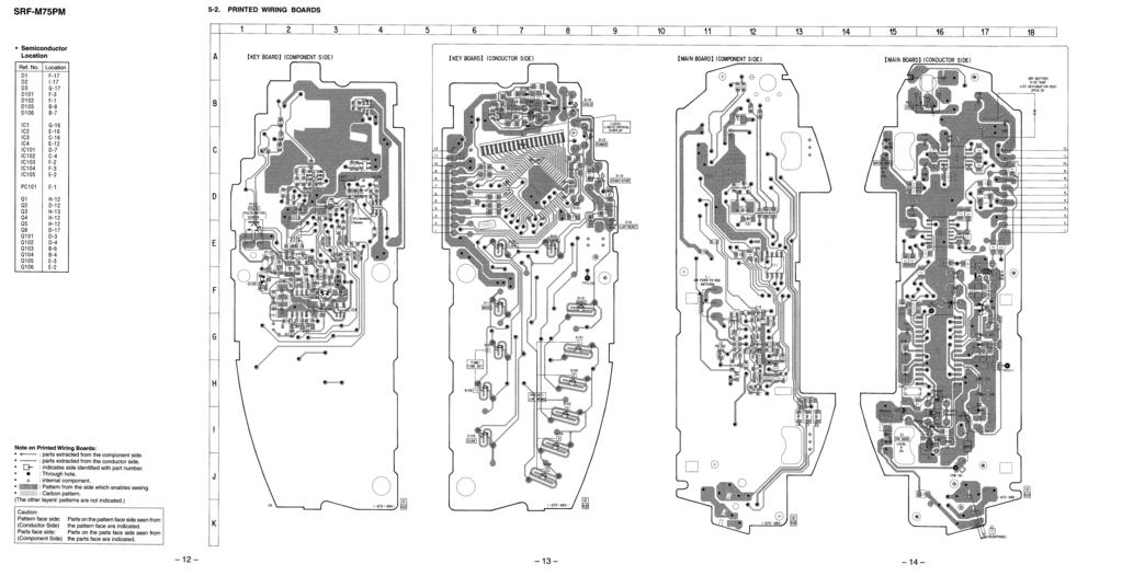
7 Adjustment Location: MAIN BOARD (Component Side) MAIN BOARD (Conductor Side) L4 AM VCO Voltage Adjustment RT1 FM Free-Run Adjustment TP (MPX) CT1 AM Tracking Adjustment L1 AM Tracking Adjustment CT2 L2 FM Tracking Adjustment TP (VT) TP (FM IN) J1 T1 AM IF Adjustment 7
8 PULSE MONITOR SECTION Luminance Adjustment digital voltmeter KEY board TP (LED) + Procedure: 1. Connect the digital voltmeter to TP (LED) on the KEY board. 2. Press the [PULSE] button (S112) to enter pulse monitor mode. 3. Adjust RT102 for 0.24 V reading on the digital voltmeter. Specification: 0.22 to 0.26 V Adjustment Location: KEY BOARD (Component Side) KEY BOARD (Conductor Side) RT102 Luminance Adjustment TP (LED) 8
9 SECTION 5 DIAGRAMS SRF-M75PM 5-1. BLOCK DIAGRAM CF1 10.7MHz VREF B+ S1 FM SENS DX LOCAL (PANAMA) L1 AM FERRITE-ROD ANTENNA CT1, L1 AM TRACKING CT1 B.P.F. BPF1 CT2, L2 FM TRACKING D1-1 L2 FM RF CT2 D FM/AM FRONT-END, FM/AM DET, MPX IC1 FM RF IN FM RF AM RF IN L4 AM VCO VOLTAGE FM FRONT-END AM FRONT-END AM OSC FM OSC FM/AM MIX OUT CF3: EXCEPT PANAMA CF4, 5: PANAMA 10.7MHz T1 AM IF CF2 450kHz AM IF BUFFER Q4, 5 14 FM IF IN AM IF IN FM DISCRI BAND SELECT FM IF AMP/ DISCRI TUNING INDICATOR AM IF AMP/ DET TUNE IND 12 AFC1/AGC REG 9 21 PILOT DET LPF2 REGULATOR PD1 PD2 3 PILOT DET LPF1 2 VCC 7 1/2 COUNTER 1/2 COUNTER PLL LPF1 1 DECODER AMP SWITCH L.P.F. PLL LPF2 VCO 29 L-CH OUT R-CH OUT ST IND VCO IN1 IN2 BASS BOOST AMP IC2 BASS BOOST CONTROL DET IN DET 12 OUT1 OUT2 LP GAIN ON OFF RV1 VOL 1 2 S2 MEGA BASS 2 4 IN1 IN2 HEADPHONE AMP IC3 POWER AMP POWER AMP MUTE CONTROL MT/SW 10 OUT1 OUT2 9 7 L4 AM OSC D1-2 D3 L3 FM OSC FM/AM BAND SELECT SWITCH Q3 B+ RT1 FM FREE-RUN + LOW-PASS FILTER Q101 FM VCO BUFFER Q COMPARATOR IC4 (1/2) COMPARATOR IC4 (2/2) 7 1 J1 2 (HEADPHONE) EO KS0 KS3 VCOL KR0 KR3 DATA VCOH CK CS PULSE IN XOUT XIN AM IF IN BAND COM0 COM3 SYSTEM CONTROLLER, LIQUID CRYSTAL DISPLAY DRIVER, KEY CONTROL IC101 SEG0 SEG14 PULSE POWER POWER IF ON CMP IN MUTE CE BEEP X101 75kHz LIQUID CRYSTAL DISPLAY LCD101 VOLTAGE DETECT IC102 KEY MATRIX S DI 4 DO EEPROM IC SK CS SYSTEM CONTROLLER (IC101), EEPROM (IC105) B+ FM/AM TUNER (IC1), HEADPHONE AMP (IC3) B+ BASS BOOST AMP (IC2) B+ RIPPLE FILTER Q2 DRY BATTERY SIZE AAA (IEC DESIGNATION R03) 2PCS. 3V B+ PLL LOW-PASS FILTER CIRCUIT B+ D105 DC/DC CONVERTER Q103, T101 B+ SWITCH Q104 PC101 PULSE (PULSE METER SENSOR) PULSE METER COMPARATOR IC103 BUFFER Q105, 106 AM IF AMP CIRCUIT B+ B+ SWITCH Q6 RT SIGNAL PATH : FM : AM LUMINANCE PULSE METER CIRCUIT B+ REGULATOR IC104 B+ SWITCH Q
10
11 5-3. SCHEMATIC DIAGRAM See page 19 for IC Block Diagrams. SRF-M75PM Waveforms KEY Board 1 XOUT 200 mv/div, 10 µs/div 208 m Vp-p 13.3 µs 2 Q103 Base-1, Collector-2 (RADIO ON mode) 200 mv/div, 100 ns/div 616 m Vp-p 243 ns 3 Q103 Collector-1 (RADIO ON mode) 2 V/DIV, 100 ns/div 4.9 Vp-p Note on Schematic Diagram: All capacitors are in µf unless otherwise noted. pf: µµf 50 WV or less are not indicated except for electrolytics and tantalums. All resistors are in Ω and 1 /4 W or less unless otherwise specified. : internal component. C : panel designation. U : B+ Line. H : adjustment for repair. Power voltage is dc 3 V and fed with regulated dc power supply from battery terminal. Voltages and waveforms are dc with respect to ground under no-signal (detuned) conditions. no mark : FM ( ) : AM [ ] : PULSE : Impossible to measure Voltages are taken with a VOM (Input impedance 10 MΩ). Voltage variations may be noted due to normal production tolerances. Waveforms are taken with a oscilloscope. Voltage variations may be noted due to normal production tolerances. Circled numbers refer to waveforms. Signal path. F : FM f : AM 243 ns
12 SECTION 6 EXPLODED VIEW KEY SECTION 7 ELECTRICAL PARTS LIST IC Block Diagrams MAIN Board IC1 CXA1238M-T6 1 GND PLL LPF VCO MONO/STEREO SELECT MPX REGULATOR MUTING DECORD AMP REGULATOR FM FRONT-END AM FRONT-END AUTO BLEND RIPPLE FILTER PLL LPF1 PILOT DET LPF2 PILOT DET LPF2 ST IND/VCO CHECK MPX REG VCO FM DISCRI MUTE AM OSC AFC 1/2 COUNTER 1/2 COUNTER R-CH OUT FM OSC REG L-CH OUT BAND-PASS MUTE TUNING INDICATOR IC2 LA3550MTP-1 IC3 LA4533M IN-1 IN-2 HP-1 HP-2 LP-IN LP-GAIN LP-OUT ON/OFF 10 REF 9 8 PD1 PD2 14 OUT-1 13 OUT-2 12 DET IN 11 DET OUT VCC GND FM RF AM RF IN FM RF IN VCC RIPPLE FILTER AGC AFC FM GND FM IF/ DISCRI AM IF/ DET 12 AGC AFC2 GND TUNE IND FM/AM FE OUT FM IF IN AM IF IN BAND SELECT PWR 1 POWER SWITCH MUTE 10 MUTE R-IN GND 2 3 BIAS AMP 9 8 R-OUT GND L-IN 4 AMP 7 L-OUT REG 5 6 VCC 5-4. IC PIN FUNCTION DESCRIPTION KEY BOARD IC101 µpd17073gb-556-1a7 (SYSTEM CONTROLLER, LIQUID CRYSTAL DISPLAY DRIVER, KEY CONTROL) Pin No. Pin Name I/O Description 1 IF ON O Power on/off control signal output for the AM IF amplifier circuit L : power on L is output when AM scan mode 2 POWER O Power on/off control signal output for the radio system power supply H : power on 3 BAND O FM/AM band selection signal output terminal L : AM, H : FM 4 PULSE POWER O Power on/off control signal output for the pulse meter circuit H : power on 5 MUTE O Muting on/off control signal output to the headphone amplifier (IC3) L : muting on 6 to 9 KS0 to KS3 O Key scan signal output for the key matrix 10 to 13 KR0 to KR3 I Key return signal input for the key matrix 14 CK O Serial clock signal output to the EEPROM (IC105) 15 DATA I/O Two-way data bus with the EEPROM (IC105) 16 CS O Chip select signal output to the EEPROM (IC105) 17 AM IF IN I AM intermediate frequency detect signal input terminal 18 GND Ground terminal 19 EO O PLL error signal output terminal 20 VCOL I AM VCO input terminal 21 VCOH I FM VCO input terminal 22 VREG1 Power supply terminal (connected to the coupling capacitor) 23 VDD Power supply terminal (+3V) 24 XOUT O System clock output terminal (75 khz) 25 XIN I System clock input terminal (75 khz) 26 VREG2 Power supply terminal (connected to the coupling capacitor) 27 VLCD0 28 CAP0 29 CAP1 Terminal for doubler circuit capacitor connection to develop liquid crystal display drive voltage 30 VLCD2 31 to 34 COM0 to COM3 O Common drive signal output to the liquid crystal display (LCD101) 35 to 49 SEG0 to SEG14 O Segment drive signal output to the liquid crystal display (LCD101) 50 CE I Power failure detection signal input from the voltage detect (IC102) Normally: H 51 PULSE IN I Pulse meter input terminal (detecting a falling edge) 52 BEEP O Beep sound drive signal output terminal 53 CMP IN I Scan stop detect signal input terminal 54 PB1 I Initialize signal input for the destination select (fixed at H in this set) 55 PB2 I Initialize signal input for the destination select (fixed at L in this set) 56 PB3 I Initialize signal input for the destination select (US, Canadian, E models: fixed at L, AEP, Australian models: fixed at H ) NOTE: -XX and -X mean standardized parts, so they may have some difference from the original one. Color Indication of Appearance Parts Example: KNOB, BALANCE (WHITE)... (RED) Parts Color Cabinet's Color 1 B 22 B CN101 not supplied Items marked * are not stocked since they are seldom required for routine service. Some delay should be anticipated when ordering these items. The mechanical parts with no reference number in the exploded views are not supplied. Accessories and packing materials are given in the last of the electrical parts list LCD101 A 24 7 PC101 C 8 9 not supplied Ref. No. Part No. Description Remark Ref. No. Part No. Description Remark 1 X CABINET (FRONT) ASSY SWITCH, RUBBER KEY HOLDER (BUTTON) BUTTON (POWER) SCREW (B1.7X4), TAPPING L TERMINAL (+ ), BATTERY TERMINAL ( ), BATTERY TERMINAL (+), BATTERY * 19 A A MAIN BOARD, COMPLETE (EXCEPT Panama) * 19 A A MAIN BOARD, COMPLETE (Panama) A 19 C NOTE: Due to standardization, replacements in the parts list may be different from the parts specified in the diagrams or the components used on the set. -XX and -X mean standardized parts, so they may have some difference from the original one. RESISTORS All resistors are in ohms. METAL: Metal-film resistor. METAL OXIDE: Metal oxide-film resistor. F: nonflammable Ref. No. Part No. Description Remark * A A KEY BOARD, COMPLETE (US, Canadian, Panama) * A A KEY BOARD, COMPLETE (AEP, Australian) ******************** HOLDER (LCD) SHEET, SHIELD <CAPACITOR> C TANTALUM CHIP 100uF 20% 4V C CERAMIC CHIP 0.001uF 10% 50V C CERAMIC CHIP 0.001uF 10% 50V C CERAMIC CHIP 0.001uF 10% 50V C CERAMIC CHIP 0.001uF 10% 50V C TANTALUM CHIP 4.7uF 20% 6.3V C CERAMIC CHIP 0.1uF 10% 16V C CERAMIC CHIP 33PF 5% 50V C CERAMIC CHIP 15PF 5% 50V C CERAMIC CHIP 0.1uF 10% 16V C CERAMIC CHIP 0.1uF 10% 16V C CERAMIC CHIP 0.01uF 10% 50V C CERAMIC CHIP 0.1uF 10% 25V C CERAMIC CHIP 0.01uF 10% 25V C CERAMIC CHIP 470PF 10% 50V C CERAMIC CHIP 0.33uF 10% 16V C CERAMIC CHIP 0.001uF 10% 50V C CERAMIC CHIP 1uF 16V C CERAMIC CHIP 22PF 5% 50V C CERAMIC CHIP 0.1uF 25V C TANTALUM CHIP 10uF 20% 6.3V C CERAMIC CHIP 0.1uF 25V C CERAMIC CHIP 0.01uF 10% 25V C TANTALUM CHIP 100uF 20% 4V C TANTALUM CHIP 22uF 20% 4V Items marked * are not stocked since they are seldom required for routine service. Some delay should be anticipated when ordering these items. SEMICONDUCTORS In each case, u: µ, for example: ua.. : µa.. upa.. : µpa.. upb.. : µpb.. upc.. : µpc.. upd.. : µpd.. CAPACITORS uf: µf COILS uh: µh When indicating parts by reference number, please include the board. Ref. No. Part No. Description Remark C TANTALUM CHIP 10uF 20% 6.3V C CERAMIC CHIP 0.001uF 10% 50V C CERAMIC CHIP 0.001uF 10% 50V C CERAMIC CHIP 100PF 5% 50V C CERAMIC CHIP 1uF 16V C CERAMIC CHIP uF 10% 50V C CERAMIC CHIP uF 10% 50V C TANTALUM CHIP 4.7uF 20% 6.3V <CONNECTOR> CN CONDUCTIVE BOARD, CONNECTION <DIODE> D DIODE 1SS226 D DIODE RB706D-40-T146 D DIODE 1SS355TE-17 D DIODE DTZ-TT11-13 <IC> IC IC upd17073gb-556-1a7 IC IC S-80822ALNP-EAB-T2 IC IC BA4510F-T1 IC IC RN5RZ20BA-TR IC IC AK93C45AV-L <SHORT> JC METAL CHIP 0 5% 1/16W (AEP, Australian) JC METAL CHIP 0 5% 1/16W (US, Canadian, Panama) JC METAL CHIP 0 5% 1/16W JC METAL CHIP 0 5% 1/16W <COIL> ADAPTOR CABINET (REAR) (EXCEPT AEP) CABINET (REAR) (AEP) SCREW (B1.7X8), TAPPING SPRING, RING PACKING, KNOB KNOB (VOL) KNOB (A) CLIP (A), BELT CLIP (B), BELT LID, BATTERY CASE BUSHING HOLDER (BAR ANT) * 22 A A KEY BOARD, COMPLETE (US, Canadian, Panama) * 22 A A KEY BOARD, COMPLETE (AEP, Australian) HOLDER (LCD) SHEET, SHIELD CN CONDUCTIVE BOARD, CONNECTION L ANTENNA, FERRITE-ROD (AM) LCD DISPLAY PANEL, LIQUID CRYSTAL PC PHOTO INTERRUPTER GP2L09B (PULSE) (PULSE METER SENSOR) C CERAMIC CHIP 0.22uF 10% 16V C TANTALUM CHIP 22uF 20% 4V C CERAMIC CHIP 0.22uF 10% 10V C TANTALUM CHIP 100uF 20% 4V C TANTALUM CHIP 10uF 20% 6.3V C CERAMIC CHIP 0.1uF 10% 25V C TANTALUM CHIP 10uF 20% 6.3V C CERAMIC CHIP 0.001uF 10% 50V C CERAMIC CHIP 0.001uF 10% 50V C CERAMIC CHIP 0.001uF 10% 50V C CERAMIC CHIP 0.001uF 10% 50V L INDUCTOR CHIP 220uH LCD <LIQUIDCRYSTALDISPLAY > DISPLAY PANEL, LIQUID CRYSTAL <PHOTOINTERRUPTER > PC PHOTO INTERRUPTER GP2L09B (PULSE) (PULSE METER SENSOR)
13 KEY MAIN Ref. No. Part No. Description Remark Ref. No. Part No. Description Remark <TRANSISTOR> Q TRANSISTOR XN6501 Q TRANSISTOR XN4608 Q TRANSISTOR XN6501 Q TRANSISTOR XN4608 Q TRANSISTOR 2SC1623-L5L6 Q TRANSISTOR 2SC1623-L5L6 <RESISTOR> R RES, CHIP 4.7K 5% 1/10W R RES, CHIP 47K 5% 1/10W R RES, CHIP 47K 5% 1/10W R RES, CHIP 47K 5% 1/10W R RES, CHIP 100K 5% 1/10W R RES, CHIP 10K 5% 1/16W R RES, CHIP 10K 5% 1/16W R RES, CHIP 10K 5% 1/16W R METAL CHIP 100K 5% 1/16W R RES, CHIP 1K 5% 1/10W R RES, CHIP 1K 5% 1/10W R METAL CHIP 1K 5% 1/16W R METAL CHIP 1K 5% 1/16W R METAL CHIP 100K 5% 1/16W R METAL CHIP 22K 5% 1/16W R METAL CHIP 220K 5% 1/16W <VARIABLERESISTOR > RT RES, ADJ, CARBON 220 R METAL CHIP 1K 5% 1/16W R METAL CHIP 1K 5% 1/16W R METAL CHIP 1K 5% 1/16W R METAL CHIP 1K 5% 1/16W R RES, CHIP 10K 5% 1/16W R RES, CHIP 10K 5% 1/16W R RES, CHIP 10K 5% 1/16W R RES, CHIP 10K 5% 1/16W R RES, CHIP 10K 5% 1/16W R RES, CHIP 1K 5% 1/10W R METAL CHIP 10K 5% 1/16W R RES, CHIP 10K 5% 1/16W R METAL CHIP 330K 5% 1/10W R RES, CHIP 10K 5% 1/16W R METAL CHIP 100K 5% 1/16W R RES, CHIP 10K 5% 1/16W R METAL CHIP 100K 5% 1/16W R METAL CHIP 3.3K 5% 1/16W R RES, CHIP 1K 5% 1/10W R RES, CHIP 100K 5% 1/10W R RES, CHIP 100K 5% 1/10W R RES, CHIP 47K 5% 1/10W R RES, CHIP 47 5% 1/10W R METAL CHIP 2.2K 5% 1/16W R METAL CHIP 100K 5% 1/16W R RES, CHIP 10K 5% 1/16W R METAL CHIP 1K 5% 1/16W R METAL CHIP 47 5% 1/16W R METAL CHIP 270 5% 1/16W R METAL CHIP 1K 5% 1/16W R METAL CHIP 1M 5% 1/16W R METAL CHIP 0 5% 1/16W R METAL CHIP 470K 5% 1/16W R METAL CHIP 100K 5% 1/16W R METAL CHIP 100K 5% 1/16W R METAL CHIP 2.2K 5% 1/16W R METAL CHIP 2.2K 5% 1/16W R METAL CHIP 22K 5% 1/16W R METAL CHIP 47K 5% 1/16W R RES, CHIP 10K 5% 1/16W R METAL CHIP 47K 5% 1/16W R METAL CHIP 47K 5% 1/16W R RES, CHIP 10K 5% 1/16W <SWITCH> S SWITCH, TACTIL (POWER) S SWITCH, TACTIL (HOLD) S SWITCH, TACTIL (START/STOP) S SWITCH, TACTIL (LAP/RESET) <TRANSFORMER> T TRANSFORMER, DC-DC CONVERTER <VIBRATOR> X VIBRATOR, CRYSTAL (75kHz) ************************************************************** * A A MAIN BOARD, COMPLETE (EXCEPT Panama) * A A MAIN BOARD, COMPLETE (Panama) ********************* HOLDER (BAR ANT) < BAND PASS FILTER > BPF FILTER, BAND PASS < CAPACITOR > C CERAMIC CHIP 0.001uF 5% 50V C CERAMIC CHIP 0.001uF 5% 50V C CERAMIC CHIP 9PF 0.25PF 50V C CERAMIC CHIP 3PF 0.25PF 50V C CERAMIC CHIP 0.047uF 10% 25V C CERAMIC CHIP 390PF 5% 50V C CERAMIC CHIP 15PF 5% 50V C CERAMIC CHIP 100PF 5% 50V C CERAMIC CHIP 0.01uF 10% 50V C ELECT 10uF 20% 16V C ELECT 10uF 20% 16V C ELECT 3.3uF 20% 50V C CERAMIC CHIP 0.47uF 10V C TANTALUM CHIP 4.7uF 20% 6.3V C CERAMIC CHIP 0.01uF 10% 25V C CERAMIC CHIP 0.1uF 25V C TANTALUM CHIP 10uF 20% 6.3V C CERAMIC CHIP 1uF 16V C TANTALUM CHIP 4.7uF 20% 6.3V C ELECT 100uF 20% 10V 23
14 MAIN Ref. No. Part No. Description Remark Ref. No. Part No. Description Remark C CERAMIC CHIP 0.1uF 10% 25V C CERAMIC CHIP 0.022uF 10% 25V C CERAMIC CHIP 0.022uF 10% 25V C CERAMIC CHIP 1uF 16V C CERAMIC CHIP 0.33uF 25V C CERAMIC CHIP 0.33uF 25V C CERAMIC CHIP 0.01uF 10% 50V C CERAMIC CHIP 0.1uF 10% 25V C CERAMIC CHIP 0.047uF 10% 25V C TANTALUM CHIP 3.3uF 20% 6.3V < DIODE > D DIODE SVC347S-TL D DIODE 1T362 D DIODE 1T362 < IC > IC IC CXA1238M-T6 IC IC LA3550MTP-1 IC IC LA4533M IC IC BA10393F-E2 C ELECT 3.3uF 20% 50V C ELECT 10uF 20% 16V C CERAMIC CHIP 0.33uF 25V C CERAMIC CHIP 0.33uF 25V C CERAMIC CHIP 12PF 5% 50V C CERAMIC CHIP 0.001uF 10% 50V C TANTALUM CHIP 100uF 20% 6.3V C CERAMIC CHIP 100PF 5% 50V C CERAMIC CHIP 100PF 5% 50V C TANTALUM CHIP 100uF 20% 4V C ELECT 220uF 20% 4V C CERAMIC CHIP 0.1uF 10% 25V C CERAMIC CHIP 0.1uF 10% 25V C ELECT 100uF 20% 10V C ELECT 100uF 20% 10V C CERAMIC CHIP 0.01uF 10% 50V C CERAMIC CHIP 0.01uF 10% 25V C CERAMIC CHIP 0.01uF 10% 50V C CERAMIC CHIP 0.01uF 10% 25V C CERAMIC CHIP 0.01uF 10% 25V C TANTALUM CHIP 10uF 20% 6.3V C ELECT 470uF 20% 4V C ELECT 470uF 20% 4V C CERAMIC CHIP 0.001uF 10% 50V C CERAMIC CHIP 0.1uF 10% 25V C CERAMIC CHIP 0.01uF 10% 50V C CERAMIC CHIP 100PF 5% 50V C CERAMIC CHIP 100PF 5% 50V C CERAMIC CHIP 100PF 5% 50V C CERAMIC CHIP 100PF 5% 50V C CERAMIC CHIP 100PF 5% 50V C CERAMIC CHIP 0.01uF 10% 25V C CERAMIC CHIP 0.01uF 10% 50V C CERAMIC CHIP 0.1uF 10% 25V < FILTER > CF FILTER, CERAMIC CF FILTER, CERAMIC CF FILTER, CERAMIC (EXCEPT Panama) CF FILTER, CERAMIC (Panama) CF FILTER, CERAMIC (Panama) < TRIMMER > CT CAP, TRIMMER 10PF CT CAP, TRIMMER 10PF < JACK > J JACK (SMALL TYPE) (DIA. 3.5) (2) < SHORT > JC SHORT 0 (Panama) < COIL > L ANTENNA, FERRITE-ROD (AM) L COIL, AIR-CORE L INDUCTOR 82nH L COIL (OSC) L INDUCTOR 4.7uH L INDUCTOR 4.7uH L INDUCTOR 4.7uH L INDUCTOR 47uH < TRANSISTOR > Q TRANSISTOR 2SC2223-F13 Q TRANSISTOR 2SC1623-L5L6 Q TRANSISTOR 2SC4081-R Q TRANSISTOR 2SC4081-R Q TRANSISTOR 2SC4081-R Q TRANSISTOR 2SB624-BV345 < RESISTOR > R RES, CHIP 100K 5% 1/10W R RES, CHIP 100K 5% 1/10W R METAL CHIP 10K 5% 1/10W R METAL CHIP 2.2K 5% 1/10W R METAL CHIP 22K 5% 1/16W R RES, CHIP 1M 5% 1/10W R METAL CHIP 220 5% 1/16W R METAL CHIP 1K 5% 1/16W R METAL CHIP 8.2K 5% 1/16W R METAL CHIP 3.3K 5% 1/16W R METAL CHIP 220K 5% 1/16W R METAL CHIP 2.2K 5% 1/16W R METAL CHIP 220 5% 1/10W R METAL CHIP 10 5% 1/10W R METAL CHIP 3.3K 5% 1/16W R METAL CHIP 3.3K 5% 1/16W R METAL CHIP 220K 5% 1/16W R RES, CHIP 4.7K 5% 1/10W R METAL CHIP 150K 5% 1/10W R METAL CHIP 150K 5% 1/10W 24
15 MAIN Ref. No. Part No. Description Remark Ref. No. Part No. Description Remark R METAL CHIP 100K 5% 1/16W R METAL CHIP 1K 5% 1/16W R RES, CHIP 10K 5% 1/16W R RES, CHIP 10K 5% 1/16W R METAL CHIP 1K 5% 1/16W R METAL CHIP 1K 5% 1/16W R METAL CHIP 10K 5% 1/10W R METAL CHIP 10K 5% 1/10W R RES, CHIP 68K 5% 1/10W R METAL CHIP 2.2K 5% 1/16W R METAL CHIP 2.2K 5% 1/16W R METAL CHIP 100K 5% 1/16W R METAL CHIP 2.2K 5% 1/16W R METAL CHIP 100 5% 1/16W R METAL CHIP 100K 5% 1/16W R METAL CHIP 470 5% 1/16W R METAL CHIP 47 5% 1/16W R METAL CHIP 100 5% 1/16W R METAL CHIP 10 5% 1/16W R RES, CHIP 100K 5% 1/10W R METAL CHIP 82K 5% 1/10W R METAL CHIP 100K 5% 1/16W R METAL CHIP 100K 5% 1/16W < VARIABLE RESISTOR > RT RES, ADJ, CARBON 4.7K RV RES, BAR, CARBON 20K/20K (VOL) < SWITCH > S SWITCH, SLIDE (FM SENS) S SWITCH, SLIDE (MEGA BASS) < TRANSFORMER > T TRANSFORMER, IF ************************************************************** MISCELLANEOUS ************** SWITCH, RUBBER KEY ************************************************************** ACCESSORIES & PACKING MATERIALS ******************************** STRAP, HAND MANUAL, INSTRUCTION (ENGLISH, FRENCH, GERMAN, SPANISH) (Canadian, AEP, Panama, Australian) MANUAL, INSTRUCTION (ENGLISH) (US) MANUAL, INSTRUCTION (ITALIAN, DUTCH, FINNISH, SWEDISH) (AEP) HEADPHONE MDR-W14G//K SET 25
16 SRF-M75PM Sony Corporation Personal Audio Company 26 99D Printed in Japan Published by General Engineering Dept.
SRF-M75PM SERVICE MANUAL FM STEREO/AM PLL SYNTHESIZED RADIO. US Model Canadian Model AEP Model E Model Australian Model. Ver
 SRF-M75PM SERVICE MANUAL Ver 1.0 1999. 04 US Model Canadian Model AEP Model E Model Australian Model SPECIFICATIONS US, Canadian, and E models AEP, Australian models FM STEREO/AM PLL SYNTHESIZED RADIO
SRF-PSY03 SERVICE MANUAL FM STEREO/AM RADIO. US Model SPECIFICATIONS. Photo: Violet model MICROFILM
 SRF-PSY03 SERVICE MANUAL US Model Photo: Violet model SPECIFICATIONS STEREO/ RADIO MICROFILM TABLE OF CONTENTS 1. GENERAL... 3. DISASSEMBLY... 4 Notes on chip component replacement Never reuse a disconnected
SRF-T615 SERVICE MANUAL FM STEREO/AM PLL SYNTHESIZED RADIO. Tourist Model. Ver SPECIFICATIONS MICROFILM
 SRF-T615 SERVICE MANUAL Ver 1.0 1999.10 Tourist Model SPECIFICATIONS FM STEREO/AM PLL SYNTHESIZED RADIO MICROFILM TABLE OF CONTENTS Specifications... 1 1. GENERAL Location and Function of Controls... 2
SRF-M55 SERVICE MANUAL FM STEREO PLL SYNTHESIZED RADIO. AEP Model E Model Chinese Model. Ver SPECIFICATIONS MICROFILM
 SRF-M SERVICE MANUAL Ver.0 999.09 AEP Model E Model Chinese Model SPECIFICATIONS FM STEREO PLL SYNTHESIZED RADIO MICROFILM TABLE OF CONTENTS Specifications.... GENERAL Location and Function of Controls...
ICF-C112 SERVICE MANUAL FM/AM CLOCK RADIO. E Model. Ver Sony Corporation SPECIFICATIONS
 SERVICE MANUAL E Model Ver 1.0 2003. 03 SPECIFICATIONS Time display: 12-hour system Frequency range: : 87.5-108 MHz AM: 530-1710 khz Speaker: Approx. 6.6 cm (2 5/8 inches) dia., 8 ohm Power output: 120
SPECIFICATIONS. Power output 3.6mW + 3.6mW (at 10% harmonic distortion) Power requirements 1.5 V DC, one R03 (rize AAA)
 Power requirements 1.5 V DC, one R03 (rize AAA)") SERVICE MANUAL Ver. 004.05 E Model Australian Model Chinese Model Tourist Model SPECIFICATIONS Frequency range : 87.5-08 MHz (EXCEPT Tourist model) : 76-08 MHz (Tourist model) : 530-605kHz Output (stereo
SERVICE MANUAL Ver. 004.05 E Model Australian Model Chinese Model Tourist Model SPECIFICATIONS Frequency range : 87.5-08 MHz (EXCEPT Tourist model) : 76-08 MHz (Tourist model) : 530-605kHz Output (stereo
ICF-F11S/F12S SERVICE MANUAL FM/SW/MW 3 BAND RADIO. E Model. Ver
 SERVICE MANUAL E Model Ver.. 2007.2 Photo : ICF-F2S SPECIFICATIONS Frequency range: Band ICF-FS ICF-F2S 87.5-08 MHz 87.5-08 MHz MW 530-605 khz 530-605 khz SW 2.3-7.35 MHz 5.9-8 MHz Notes on chip component
Photo: SRS-Z750PC SPECIFICATIONS. Stereo mini jack (INPUT) (SRS-Z750) Stereo mini jack 2 (INPUT 1, 2) (SRS-Z750PC)
 (SRS-Z750) Stereo mini jack 2 (INPUT 1, 2) (SRS-Z750PC)") SRS-Z750/Z750PC SERVICE MANUAL Ver 1.0 1998. 07 US Model Canadian Model AEP Model UK Model E Model Australian Model Left speaker Right speaker Photo: SRS-Z750PC SPECIFICATIONS Amplifier section Power output
SRS-Z750/Z750PC SERVICE MANUAL Ver 1.0 1998. 07 US Model Canadian Model AEP Model UK Model E Model Australian Model Left speaker Right speaker Photo: SRS-Z750PC SPECIFICATIONS Amplifier section Power output
SUPPLEMENT-1. File this supplement with the service manual. Subject : 1. Change of Illumination Color 2. Change of Main and Display Boards
 MDX-C6500X SERVICE MANUAL US Model Canadian Model E Model SUPPLEMENT-1 File this supplement with the service manual. Subject : 1. Change of Illumination Color 2. Change of Main and Display Boards (ECN-CSA02152,
ICF-C793/C793L SERVICE MANUAL FM/AM PLL SYNTHESIZED CLOCK RADIO FM/MW/LW PLL SYNTHESIZED CLOCK RADIO. US Model Canadian Model Australian Model
 ICF-C793/C793L SERVICE MANUAL Ver 1.0 1999. 02 US Model Canadian Model Australian Model ICF-C793 AEP Model ICF-C793/C793L UK Model ICF-C793L Photo: ICF-C793L SPECIFICATIONS ICF-C793 FM/AM PLL SYNTHESIZED
Illustration : MDR-IF330R SPECIFICATIONS
 MDR-IF230/IF330R SERVICE MANUAL Ver 1.1 2000. 06 US Model Canadian Model E Model Australian Model MDR-IF230/IF330R Tourist Model MDR-IF330R Illustration : MDR-IF330R MDR-IF230 is the component model block
STEREO POWER AMPLIFIER. AEP Model UK Model
 XM-5020X SERVICE MANUAL AEP Model UK Model This set has almost the same specifications as the XM-502X. This service manual only describes the differences from the XM-502X. Refer to the appropriate service
XM-502X. SERVICE MANUAL Ver STEREO POWER AMPLIFIER. US Model Canadian Model AEP Model UK Model E Model. Sony Corporation SPECIFICATIONS
 XM-502X SERVICE MANUAL Ver 1.1 2001. 08 US Model Canadian Model AEP Model UK Model E Model SPECIFICATIONS Circuit system OTL (output transformerless) circuit Pulse power supply Inputs RCA pin jacks High
ECM-S80 SERVICE MANUAL ELECTRET CONDENSER MICROPHONE. US Model Canadian Model AEP Model E Model. Ver
 SERVICE MANUAL Ver.0 00. 0 US Model Canadian Model AEP Model E Model SPECIFICATIONS Type Electret condenser microphone Cord ø. mm ( 3 / 3 in.)ofc litz cord ( core shielded) Length:Approx.70 cm (7 5 / 8
CFS-717S SERVICE MANUAL RADIO CASSETTE-CORDER. E Model. Ver SPECIFICATIONS
 CFS-717S SERVICE MANUAL Ver 1.1 1999. 11 E Model Model Name Using Similar Mechanism Tape Transport Mechanism Type CFS-W475 MF-W475 SPECIFICATIONS RADIO CASSETTE-CORDER MICROFILM Ver 1.1 1999. 11 MODEL
ICF-C763/C763L SERVICE MANUAL FM/AM PLL SYNTHESIZED CLOCK RADIO FM/MW/LM PLL SYNTHESIZED CLOCK RADIO. US Model Canadian Model ICF-763 ICF-763L
 SERVICE MANUAL Ver.0 2004.05 US Model Canadian Model ICF-C763 AEP Model ICF-C763/C763L UK Model ICF-C763L SPECIFICATIONS Time display UK, North and South America Other countries/regions 2-hour system 24-hour
 CFD-S23 SERVICE MANUAL Ver 1.0 1998. 08 SUPPLEMENT - 1 File this Supplement with the Service Manual. Subject : r EAST EUROPEAN AND RUSSIAN MODEL HAS BEEN ADDED r CHANGE OF BOARDS AC INLET BOARD : 1-666-267-11
Photo : WM-FX195 SPECIFICATIONS
 WM-FX193/FX195 SERVICE MANUAL Ver 1.0 2000.01 US Model WM-FX193 Canadian Model AEP Model E Model Chinese Model WM-FX193/FX195 Photo : WM-FX195 Model Name Using Similar Mechanism Tape Transport Mechanism
TA-E1 SERVICE MANUAL STEREO PRE AMPLIFIER. US Model Canadian Model AEP Model UK Model E Model Australian Model SPECIFICATIONS MICROFILM
 TA-E1 SERVICE MANUAL US Model Canadian Model AEP Model UK Model E Model Australian Model SPECIFICATIONS STEREO PRE AMPLIFIER MICROFILM 1 SAFETY CHECK-OUT After correcting the original service problem,
XM-2252HX SERVICE MANUAL STEREO POWER AMPLIFIER. US Model Canadian Model AEP Model UK Model SPECIFICATIONS MICROFILM
 XM-2252HX SERVICE MANUAL US Model Canadian Model AEP Model UK Model SPECIFICATIS STEREO POWER AMPLIFIER MICROFILM TABLE OF CTENTS Specifications.... SERVICING NOTE... 2 2. GENERAL... 3 3. ELECTRICAL ADJUSTMENTS
ICF-SC1/SC1PC SERVICE MANUAL PLL SYNTHESIZED SCANNING RECEIVER. US Model. Ver SPECIFICATIONS
 ICF-SC1/SC1PC SERVICE MANUAL Ver 1.0 1998.03 US Model SPECIFICATIONS Circuit system : Triple conversion superheterodyne Frequency range : 25.000 1300.000MHz (excluding cellular phone band : 823.980 849.020
SPP-ID970/ID971 SERVICE MANUAL CORDLESS TELEPHONE. US Model SPP-ID970 Canadian Model SPP-ID971
 SPP-ID970/ID971 SERVICE MANUAL Ver 1.3 2000. 12 With SUPPLEMENT-1 (9-927-617-81) With SUPPLEMENT-2 (9-927-617-82) US Model SPP-ID970 Canadian Model SPP-ID971 Photo: SPP-ID970 SPECIFICATIONS General Frequency
ICF-704S SERVICE MANUAL FM/SW/MW 3 BAND RADIO. Australian Model. Ver
 SERVICE MANUAL Australian Model Ver.0 2004. 04 SPECIFICATIONS Frequency range: Band FM SW MW ICF-704S 87.5-08.0 MHz 5.95-8 MHz 530-605 khz Speaker: Approx. 0.2 cm (4 /8 inches) dia. 8 ohms Power output:
DT-120 FM STEREO/AM/TV RADIO CONTENTS
 DT-120 FM STEREO/AM/TV RADIO CONTENTS Specification 2-3 Block Diagram 4 Alignment Instructions 5-8 Test Points Diagram.. 9 PCB Top View.. 10 PCB Bottom View........11 Wiring Diagram.........12 Troubleshooting
TA-N1 SERVICE MANUAL STEREO POWER AMPLIFIER. US Model Canadian Model AEP Model UK Model E Model Australian Model SPECIFICATIONS MICROFILM
 TA-N1 SERVICE MANUAL US Model Canadian Model AEP Model UK Model E Model Australian Model SPECIFICATIONS STEREO POWER AMPLIFIER MICROFILM 1 SAFETY CHECK-OUT After correcting the original service problem,
WM-FX463/FX465. SERVICE MANUAL Ver With SUPPLEMENT-2 ( ) RADIO CASSETTE PLAYER. US Model Canadian Model AEP Model E Model
 RADIO CASSETTE PLAYER. US Model Canadian Model AEP Model E Model") WM-FX463/FX465 SERVICE MANUAL Ver 1.1 1999. 12 With SUPPLEMENT-2 (9-923-190-82) US Model Canadian Model AEP Model E Model Photo: FX465 Model Name Using Similar Mechanism Tape Transport Mechanism Type NEW
WM-FX463/FX465 SERVICE MANUAL Ver 1.1 1999. 12 With SUPPLEMENT-2 (9-923-190-82) US Model Canadian Model AEP Model E Model Photo: FX465 Model Name Using Similar Mechanism Tape Transport Mechanism Type NEW
STEREO CASSETTE DECK. AEP Model UK Model E Model Tourist Model SPECIFICATIONS
 TC-TX101 SERVICE MANUAL AEP Model UK Model E Model Tourist Model This set is the optional stereo cassette deck that can be used only with section HCD-101 (AEP, UK model) / CMT-101 (E, Tourist model). Dolby
STR-DE135 SERVICE MANUAL FM STEREO/FM-AM-RECEIVER. US Model AEP Model UK Model SPECIFICATIONS. Photo: US model. Audio power specifications (US model)
") STR-DE135 SERVICE MANUAL US Model AEP Model UK Model Photo: US model SPECIFICATIONS Audio power specifications (US model) POWER OUTPUT AND TOTAL HARMONIC DISTORTION Muting BASS BOOST TONE Full mute + 10
STR-DE135 SERVICE MANUAL US Model AEP Model UK Model Photo: US model SPECIFICATIONS Audio power specifications (US model) POWER OUTPUT AND TOTAL HARMONIC DISTORTION Muting BASS BOOST TONE Full mute + 10
(without price) TV-1800B (NTSC) (KX-523) FEB < TUNING >
 TV-1800B (NTSC) (KX-523) FEB < TUNING >") < TUNING > (without price) TV-1800B (NTSC) (KX-523) FEB. 1997 R CONTENTS Page SPECIFICATIONS... 1 BLOCK DIAGRAM... 2 CIRCUIT OPERATIONS... 3 PRINTED CIRCUIT BOARDS... 4 PARTS LIST... 6 EXPLODED VIEW...
< TUNING > (without price) TV-1800B (NTSC) (KX-523) FEB. 1997 R CONTENTS Page SPECIFICATIONS... 1 BLOCK DIAGRAM... 2 CIRCUIT OPERATIONS... 3 PRINTED CIRCUIT BOARDS... 4 PARTS LIST... 6 EXPLODED VIEW...
200GTL ALIGNMENT REVISION: 1.0 BURKE MODEL: 200GTL REVISION: 1.2 DATE: 02/14/06. Total Pages: 6 pages. Page:1 print date: 9/23/09
 ALIGNMENT PROCEDURE MODEL: 200GTL REVISION: 1.2 DATE: 02/14/06 PREPARED BY: BURKE Total Pages: 6 pages Page:1 print date: 9/23/09 1 TEST CONDITION: 200GTL ALIGNMENT INSTRUCTION 1.0. TEST TEMPERTAURE: 77
LA1845NV. Monolithic Linear IC Single-Chip Home Stereo IC
 Ordering number : ENN*7931 LA1845NV Monolithic Linear IC Single-Chip Home Stereo IC The LA1845NV is designed for use in mini systems and is a single-chip tuner IC that provides electronic tuning functions
(without price) CTK-50 CTK-50 ELECTRIONIC KEYBOARD
 CTK-50 CTK-50 ELECTRIONIC KEYBOARD") (without price) CTK-0 CTK-0 ELECTRIONIC KEYBOARD CONTENTS Specification... 2 Block Diagram... 3 Circuit Description... 4 Troubleshooting... 7 Major Waveforms... 8 Schematic Diagrams... 9 PCB View... 11
(without price) CTK-0 CTK-0 ELECTRIONIC KEYBOARD CONTENTS Specification... 2 Block Diagram... 3 Circuit Description... 4 Troubleshooting... 7 Major Waveforms... 8 Schematic Diagrams... 9 PCB View... 11
FT-897 Alignment. Local Oscillator Adjustment. PLL Adjustment
 FT-897 Local Oscillator Adjustment Reference Frequency Adjustment a. Connect a frequency counter to TP1032. b. Adjust the trimmer capacitor (TC5001) for 67.875000MHz ±5Hz on the frequency counter. c. Connect
AM radio / FM IF stereo system IC
 radio / IF stereo system IC BAF BAF The BAF is a tuner system IC for electronic tuning for radios, IF, and MPX. It has been developed for HiFi component applications. The MPX VCO circuit requires no adjustment,
ERICSSONZ LBI MAINTENANCE MANUAL ORION MHz (Dual Bandwidth) SYNTHESIZER/RECEIVER/EXCITER BOARD B19/CMN-352 DA/DB DESCRIPTION
 SYNTHESIZER/RECEIVER/EXCITER BOARD B19/CMN-352 DA/DB DESCRIPTION") MAINTENANCE MANUAL ORION 136-174 MHz (Dual Bwidth) SYNTHESIZER/RECEIVER/EXCITER BOARD B19/CMN-352 DA/DB TABLE OF CONTENTS Page DESCRIPTION............................................ Front. Cover CIRCUIT
MAINTENANCE MANUAL ORION 136-174 MHz (Dual Bwidth) SYNTHESIZER/RECEIVER/EXCITER BOARD B19/CMN-352 DA/DB TABLE OF CONTENTS Page DESCRIPTION............................................ Front. Cover CIRCUIT
HCD-DX50/RG80 SERVICE MANUAL MINI HI-FI COMPONENT SYSTEM. Canadian Model. Australian Model E Model. Ver
 SERVICE MANUAL Ver 1.3 2003. 10 Canadian Model HCD-RG80 Australian Model E Model HCD-DX50 HCD-DX50/RG80 are the tuner, deck, CD and amplifier section in MHC-DX50/RG80. Photo : HCD-DX50 Model Name Using
LA1837M. Specifications. Monolithic Linear IC Single-Chip AM/FM Tuner IC for Home Stereo Systems. Maximum Ratings at Ta = 25 C
 Ordering number : EN8271 LA1837M Monolithic Linear IC Single-Chip AM/FM Tuner IC for Home Stereo Systems Overview The LA1837M is a single-chip AM/FM tuner IC that provides AM and FM IF and multiplex decoding
AM radio / FM IF stereo system IC
 AM radio / FM IF stereo system IC The is an AM radio and FM IF stereo system IC developed for radio cassette players. The FM circuit is comprised of a differential IF amplifier, a double-balance type quadrature
Monolithic Linear IC For Home Stereo Single-chip Tuner IC
 Ordering number : EN7930A LA1844 LA1844M Monolithic Linear IC For Home Stereo Single-chip Tuner IC Overview The LA1844, LA1844M is designed for use in mini systems and is a single-chip tuner IC that provides
STR-NX1/NX3 SERVICE MANUAL TUNER/AMPLIFIER. US Model Canadian Model AEP Model UK Model E Model Australian Model Tourist Model SPECIFICATIONS
 STR-NX1/NX3 SERVICE MANUAL US Model Canadian Model AEP Model UK Model E Model Australian Model Tourist Model STR-NX1/NX3 are the Tuner and Amplifier Section in HMC-NX1/NX3AV. Photo: STR-NX3 E model SPECIFICATIONS
SPECIFICATIONS. Tuner section. FM stereo, FM/AM superheterodyne tuner. FM tuner section. Tuning range. Intermediate frequency 450 khz
 STR-NX5MD SERVICE MANUAL AEP Model UK Model E Model STR-NX5MD is the Tuner and Amplifier Section in DHC-NX5MD. SPECIFICATIONS Amplifier section European model DIN power output (rated) 80 + 80 watts (6
LBI-38392C IC DATA MAINTENANCE MANUAL LOGIC BOARD U707 OCTAL DATA LATCH 19D902172G1 & G2 TABLE OF CONTENTS
 LBI-38392C MAINTENANCE MANUAL LOGIC BOARD 19D902172G1 & G2 U707 OCTAL DATA LATCH IC DATA TABLE OF CONTENTS Page DESCRIPTION........................................... Front.. Cover CIRCUIT ANALYSIS........................................
MVC-FD91 SERVICE MANUAL DIGITAL STILL CAMERA
 SERVICE MANUAL Ver 1.0 1998.10 US Model Canadian Model AEP Model UK Model E Model Australian Model Hong Kong Model Tourist Model Chinese Model SPECIFICATIONS DIGITAL STILL CAMERA MICROFILM MVC-FD91 4-2.
MAINTENANCE MANUAL UHF REAR COVER ASSEMBLY 19C337097G4 - G7, G11, G13
 LBI-38383D SCHEMATIC DIAGRAM MAINTENANCE MANUAL UHF REAR COVER ASSEMBLY 19C337097G4 - G7, G11, G13 TABLE OF CONTENTS Page DESCRIPTION........................................... Front Cover CIRCUIT ANALYSIS........................................
ALAN 48P 4W SMT MULTI CIRCUIT DESCRIPTION
 ALAN 48P 4W SMT MULTI CIRCUIT DESCRIPTION INTRODUCTION 1.Multi BAND:Italy,Italy-34CH, Germany-80CH, Germany,Germany-80CH-40CH-4W Spain, Europe, CEPT, England, England-CEPT, Poland,Poland-400CH, Russi a-400ch,france,sweden
LA4805V. 3 V Stereo Headphone Power Amplifier
 Ordering number : EN4469A Monolithic Linear IC LA4805V 3 V Stereo Headphone Power Amplifier Overview The LA4805V is a power IC developed for use in stereo headphones. It includes low frequency enhancement,
Low voltage high performance mixer FM IF system
 DESCRIPTION The is a low voltage high performance monolithic FM IF system incorporating a mixer/oscillator, two limiting intermediate frequency amplifiers, quadrature detector, logarithmic received signal
HF Amateur SSB Receiver
 HF Amateur SSB Receiver PCB Set for radio club project http://rhelectronics.net PCB for DIY HF Amateur SSB Receiver 20M The receiver is a simple syperheterodyne type with quartz crystal filter. The circuit
TA2149BNG,TA2149BFNG
 TOSHIBA Bipolar Linear Integrated Circuit Silicon Monolithic TA249BNG,TA249BFNG TA249BNG/BFNG V / Chip Tuner IC (for Digital Tuning System) TA249BNG, TA249BFNG are / chip tuner ICs, which are designed
RF BOARD 19D902282G1, G3, G6, G8, G10, G13 & G17. (19D902269, Sh. 2, Rev. 17)
") LBI-38383G SCHEMATIC DIAGRAM MAINTENANCE MANUAL UHF REAR COVER ASSEMBLY 19C337097G4 - G7, G11, G13, G17 TABLE OF CONTENTS Page DESCRIPTION........................................... Front Cover CIRCUIT
LBI-38383G SCHEMATIC DIAGRAM MAINTENANCE MANUAL UHF REAR COVER ASSEMBLY 19C337097G4 - G7, G11, G13, G17 TABLE OF CONTENTS Page DESCRIPTION........................................... Front Cover CIRCUIT
STD-402 SYNTHESIZED TRANSCEIVER UHF FM-NARROW BAND RADIO DATA MODULE. [Direct Mode Operation Guide] Version1.2a (April, 2000) CIRCUIT DESIGN,INC.
![STD-402 SYNTHESIZED TRANSCEIVER UHF FM-NARROW BAND RADIO DATA MODULE. [Direct Mode Operation Guide] Version1.2a (April, 2000) CIRCUIT DESIGN,INC.](/thumbs/81/83111338.jpg "STD-402 SYNTHESIZED TRANSCEIVER UHF FM-NARROW BAND RADIO DATA MODULE. [Direct Mode Operation Guide] Version1.2a (April, 2000) CIRCUIT DESIGN,INC.") SYNTHESIZED TRANSCEIVER UHF FM-NARROW BAND RADIO DATA MODULE [Direct Mode Operation Guide] Version1.2a (April, 2000) International Business Division 7557-1 Hotaka,Hotaka-machi,Minamiazumi,Nagano 399-8303.JAPAN
SYNTHESIZED TRANSCEIVER UHF FM-NARROW BAND RADIO DATA MODULE [Direct Mode Operation Guide] Version1.2a (April, 2000) International Business Division 7557-1 Hotaka,Hotaka-machi,Minamiazumi,Nagano 399-8303.JAPAN
MAINTENANCE MANUAL TRANSMITTER/RECEIVER BOARD CMN-234A/B FOR MLSU141 & MLSU241 UHF MOBILE RADIO TABLE OF CONTENTS
 MAINTENANCE MANUAL TRANSMITTER/RECEIVER BOARD CMN-234A/B FOR MLSU141 & MLSU241 UHF MOBILE RADIO TABLE OF CONTENTS DESCRIPTION... 2 CIRCUIT ANALYSIS... 2 TRANSMITTER... 2 9-Voft Regulator... 2 Exciter...
MAINTENANCE MANUAL RF BOARD 19D901835G1 ( MHz) 19D901835G2 ( MHz) FOR MVS
 19D901835G2 ( MHz) FOR MVS") D MAINTENANCE MANUAL F BOAD 19D901835G1 (136-153 MHz) 19D901835G2 (150-174 MHz) FO MVS TABLE OF CONTENTS DESCIPTION............................................... Front Cover CICUIT ANALYSIS..............................................
D MAINTENANCE MANUAL F BOAD 19D901835G1 (136-153 MHz) 19D901835G2 (150-174 MHz) FO MVS TABLE OF CONTENTS DESCIPTION............................................... Front Cover CICUIT ANALYSIS..............................................
HAMTRONICS TB901 FM EXCITER INSTALLATION, OPERATION, & MAINTENANCE
 HAMTRONICS TB901 FM EXCITER INSTALLATION, OPERATION, & MAINTENANCE GENERAL INFORMATION. The TB901 is a single-channel low power fm transmitter (exciter) designed to provide 300-600 milliwatts continuous
SPECIFICATIONS. AUDIO POWER SPECIFICATIONS (US model)
") SRVIC MANUAL Ver.. 2008.02 US Model AP Model UK Model Wood color type is the subwoofer in HT-DDW890/ DDWG800. Black color type is the subwoofer in HT-7200DH. SPCIFICATIONS AUDIO POWR SPCIFICATIONS (US
SRVIC MANUAL Ver.. 2008.02 US Model AP Model UK Model Wood color type is the subwoofer in HT-DDW890/ DDWG800. Black color type is the subwoofer in HT-7200DH. SPCIFICATIONS AUDIO POWR SPCIFICATIONS (US
SPECIFICATIONS: Subcarrier Frequency 5.5MHz adjustable, FM Modulated +/- 50KHz. 2nd 11MHz >40dB down from 5.5MHz
 Mini-kits AUDIO / SUBCARRIER KIT EME75 Version4 SPECIFICATIONS: Subcarrier Frequency 5.5MHz adjustable, FM Modulated +/- 50KHz Subcarrier Output 1.5v p-p Output @ 5.5MHz DESCRIPTION & FEATURES: The Notes
LA1787M. Functions FM front end FM IF Noise canceller Multiple AM up-conversion FM/AM switch MRC
 Ordering number : ENN6655 LA1787M Monolithic Linear IC Single-Chip Tuner IC for Car Radios http://onsemi.com Overview The LA1787M integrates all six blocks required in a car radio tuner on a single chip.
HAMTRONICS R451 UHF FM RECEIVER: INSTALLATION, OPERATION, & MAINTENANCE
 HAMTRONICS R451 UHF FM RECEIVER: INSTALLATION, OPERATION, & MAINTENANCE FUNCTIONAL DESCRIPTION. The R451 is a premium, commercial- grade single-channel uhf fm receiver. It features a GaAs FET rf amplifier
Applications Note RF Transmitter and Antenna Design Hints
 This application note covers the TH7107,TH71071,TH71072,TH7108,TH71081,TH72011,TH72031,TH7204 Single Frequency Transmitters. These transmitters have different features and cover different bands but they
AN7298FBP. FM-IF, NC, and MPX IC for car radio. ICs for FM/AM Tuner. Overview. Features. Applications
 FM-IF, NC, and MPX IC for car radio Overview The is an IC for car radio. The FM-IF, NC (Noise Canceler) and MPX functions are integrated into a single chip. The IC has the higher functions than our conventional
LC75857E LC75857W. SANYO Semiconductors DATA SHEET. Preliminary. Overview. Features. CMOS IC 1/3, 1/4 Duty LCD Display Drivers with Key Input Function
 Ordering number : ENN*798 Preliminary SANYO Semiconductors DATA SHEET LC75857E LC75857W CMOS IC 1/3, 1/4 Duty LCD Display Drivers with Key Input Function Overview The LC75857E and LC75857W are 1/3 duty
Construction. sunil kumar Electromechanical energy meters. Parts List
 Low-cost Energy Meter Using ADE7757 S.C. DWIVEDI sunil kumar Electromechanical energy meters have been the standard for metering the electricity since billing began. But these are now being gradually replaced
The Uniden Grant XL Owners Site
 The Uniden Grant XL Owners Site Modifications page for the Grant XL (For Informational purposes only) The author of this site takes NO responsibility for illegal modifications and/or use of illegally modified
unit: mm 3196-DIP30SD
 Ordering number : EN4787A Monolithic Linear IC LA1836, 1836M Single-Chip Home Stereo Electronic Tuning IC Overview AM: RF amplifier, mixer, oscillator (with ALC), IF amplifier, detector, AGC, oscillator
1 REF PART NO DESCRIPTION REMARKS QTY
 Page 1 REF PART NO DESCRIPTION REMARKS QTY 100 1033987 HOUSING ASSY., LOWER 1 102 1033832 COVER, SEALED, REAR 1 103 1033988 HOUSING ASSY., UPPER 1 104 B310204411 C.B.B. SCREW M3X10 12 105 1033813 CAP,
SERVICE MANUAL TC-WE425/WE525/ WR681 STEREO CASSETTE DECK
 SERVICE MANUAL Photo: TC-WE425 TC-WE425/WE525/ WR681 US Model TC-WE425/WR681 Canadian Model TC-WE425 AEP Model TC-WE525/WR681 UK Model TC-WE525 E Model Australian Model TC-WE425/WR681 Chinese Model TC-WE425
WIRELESS MICROPHONE. Audio in the ISM band
 WIRELESS MICROPHONE udio in the ISM band Ton Giesberts When the ISM frequency band was made available in Europe for audio applications, Circuit Design, a manufacturer of professional RF modules, decided
Building a Bitx20 Version 3
 Building a Bitx20 Version 3 The board can be broken into sections and then built and tested one section at a time. This will make troubleshooting easier as any problems will be confined to one small section.
AM/FM RADIO KIT MODEL AM/FM-108CK SUPERHET RADIO CONTAINS TWO SEPARATE AUDIO SYSTEMS: IC AND TRANSISTOR. Assembly and Instruction Manual ELENCO
 AM/FM RADIO KIT MODEL AM/FM-108CK SUPERHET RADIO CONTAINS TWO SEPARATE AUDIO SYSTEMS: IC AND TRANSISTOR Assembly and Instruction Manual ELENCO Copyright 2012 by ELENCO All rights reserved. 753510 No part
Industry s First 0.8µV RMS Noise LDO Has 79dB Power Supply Rejection Ratio at 1MHz Amit Patel
 April 15 Volume 25 Number 1 I N T H I S I S S U E patent-pending boost-buck ED driver topology 8 I 2 C programmable supervisors with EEPROM 12 Industry s First 0.8µV RMS Noise DO Has 79dB Power Supply
IC-400pro - RADIOAFICION.COM
 PROCEDURES IC-400pro - 5- PREPARATION When you adjust the contents on pages 5-5 and 5-6, SOFT- WARE, the optional CS-400PRO ADJ SOFTWARE (Rev..0 or later), *OPC- JIG CABLE (modified OPC- CLONING CABLE;
CXA1691AM/AS. FM/AM Radio. Description CXA1691AM/AS is a one-chip FM/AM radio IC designed for radio-cassette tape recorders.
 / Radio CXA69/AS Description CXA69/AS is a one-chip / radio IC designed for radio-cassette tape recorders. CXA69 CXA69AS 28 pin SOP (Plastic) 30 pin SDIP (Plastic) Features Small number of peripheral components.
ericssonz LBI-38671F MAINTENANCE MANUAL FOR UHF TRANSMITTER SYNTHESIZER MODULE 19D902780G3, G6 - G10 ASSEMBLY DIAGRAM TABLE OF CONTENTS
 F ASSEMBLY DIAGRAM MAINTENANCE MANUAL FOR UHF TRANSMITTER SYNTHESIZER MODULE 19D902780G3, G6 - G10 TABLE OF CONTENTS Page DESCRIPTION............................................. 1 GENERAL SPECIFICATIONS.....................................
REGULATOR PD 1 MUTING AMP PD 2 AUTO BLEND AMP AMP RIPPLE FILTER DC AMP AGC AFC 1 VCC. Lch OUT RIPPLE FILTER AGC AFC 2
 FM Stereo/M Radio Description The is high performance one-chip bipolar ICs designed for FM stereo/m radios. These include an FM/M front end, FM/M IF amplifier, FM/M detection output and FM stereo demodulator
TA2111NG,TA2111FG,TA2111FNG
 TOSHIBA Bipolar Linear Integrated Circuit Silicon Monolithic TA2111NG,TA2111FG,TA2111FNG 3 V AM/FM 1 Chip Tuner IC TA2111NG/FG/FNG are AM/FM 1 chip tuner ICs, which are designed for portable radios and
ERICSSONZ LBI-39123A. MAINTENANCE MANUAL FOR 21.4 MHz RECEIVER IF MODULE 12.5/25 khz CHANNEL SPACING 19D902783G7 DESCRIPTION TABLE OF CONTENTS
 A MAINTENANCE MANUAL FOR 21.4 MHz 12.5/25 khz CHANNEL SPACING 19D902783G7 TABLE OF CONTENTS Page DESCRIPTION............................................ Front Cover GENERAL SPECIFICATIONS....................................
UNISONIC TECHNOLOGIES CO., LTD
 FM/AM Radio UNISONIC TECHNOLOGIES CO., LTD DESCRIPTION The UTC CXA1191 is a one-chip FM/AM radio IC designed for radio-cassette tape recorders and headphone tape recorders. FEATURES *Small number of peripheral
CXA1619BM/BS. FM/AM Radio
 / Radio CXA69BM/BS Description CXA69BM/BS is a one-chip / radio IC designed for radio-cassette tape recorders and headphone tape recorders, and has the following functions. CXA69BM CXA69BS 28 pin SOP (Plastic)
ERICSSONZ LBI-38910A. MAINTENANCE MANUAL ORION MHz SYNTHESIZER/RECEIVER/EXCITER BOARD B19/CMN-352 A/B DESCRIPTION TABLE OF CONTENTS
 A MAINTENANCE MANUAL ORION 136-174 MHz SYNTHESIZER/RECEIVER/EXCITER BOARD B19/CMN-352 A/B TABLE OF CONTENTS Page DESCRIPTION............................................ Front. Cover CIRCUIT ANALYSIS.........................................
Assembly Manual for VFO Board 2 August 2018
 Assembly Manual for VFO Board 2 August 2018 Parts list (Preliminary) Arduino 1 Arduino Pre-programmed 1 Faceplate Assorted Header Pins Full Board Rev A 10 104 capacitors 1 Rotary encode with switch 1 5-volt
SPP-901 SERVICE MANUAL CORDLESS TELEPHONE. Canadian Model SPECIFICATIONS MICROFILM
 SERVICE MANUAL Canadian Model SPECIFICATIONS CORDLESS TELEPHONE MICROFILM SECTION DIAGRAMS -. BLOCK DIAGRAM BASE UNIT Section ANT (ANTENNA) 2MHz B.P.F. F2 RF Q2 2.2MHz SAW F MIX, OSC, LIMITER, DET U MIX
SCLK 4 CS 1. Maxim Integrated Products 1
 19-172; Rev ; 4/ Dual, 8-Bit, Voltage-Output General Description The contains two 8-bit, buffered, voltage-output digital-to-analog converters (DAC A and DAC B) in a small 8-pin SOT23 package. Both DAC
Si4825-DEMO. Si4825 DEMO BOARD USER S GUIDE. 1. Features. Table 1. Si4825 Band Sequence Definition
 Si4825 DEMO BOARD USER S GUIDE 1. Features ATAD (analog tune and analog display) AM/FM/SW radio Worldwide FM band support 64 109 MHz with 18 bands, see the Table 1 Worldwide AM band support 504 1750 khz
MAINTENANCE MANUAL AUDIO BOARDS 19D902188G1, G2 & G3
 B MAINTENANCE MANUAL AUDIO BOARDS 19D902188G1, G2 & G3 TABLE OF CONTENTS Page Front Cover DESCRIPTION............................................... CIRCUIT ANALYSIS............................................
Frequency Synthesizer Project ECE145B Winter 2011
 Frequency Synthesizer Project ECE145B Winter 2011 The goal of this last project is to develop a frequency synthesized local oscillator using your VCO from Lab 2. The VCO will be locked to a stable crystal
LBI-38849F MAINTENANCE MANUAL RF BOARD 19D902123G22 DESCRIPTION CIRCUIT ANALYSIS TABLE OF CONTENTS SYNTHESIZER CIRCUIT. Page
 MAINTENANCE MANUAL RF BOARD 19D902123G22 TABLE OF CONTENTS DESCRIPTION............................................ Front Cover CIRCUIT ANALYSIS......................................... Front Cover SYNTHESIZER
LA75505M. Adjustment Free VIF/SIF Signal Processing IC for TV/VCR
 Ordering number : ENN*6930 Monolithic Linear IC LA75505M Adjustment Free VIF/SIF Signal Processing IC for TV/VCR Preliminary Overview The LA75505M is a VIF/SIF signal processing IC for NTSC TV/VCR. It
Low Noise 300mA LDO Regulator General Description. Features
 Low Noise 300mA LDO Regulator General Description The id9301 is a 300mA with fixed output voltage options ranging from 1.5V, low dropout and low noise linear regulator with high ripple rejection ratio
THEORY OF OPERATION. TM308EUL for Cobra Nov 06,2006
 THEORY OF OPERATION TM308EUL for Cobra Nov 06,2006 This PLL controlled VHF marine mobile transceiver provides an accurate and stable multi-channel operation. The transceiver consists of 15 main sections
XR-C5100 SERVICE MANUAL FM/MW/SW CASSETTE CAR STEREO. E Model SPECIFICATIONS. Model Name Using Similar Mechanism Tape Transport Mechanism Type
 XR-C5200 SERVICE MANUAL E Model Model Name Using Similar Mechanism Tape Transport Mechanism Type XR-C5100 MG-25F-136 SPECIFICATIONS FM/MW/SW CASSETTE CAR STEREO MICROFILM XR-C5200 6-3. SCHEMATIC DIAGRAM
DIY Function Generator XR2206
 DIY Function Generator XR2206 20Hz 100KHz http://radiohobbystore.com Components List: Resistors: R1, R2 1% Metal Film 5K1 R4 1% Metal Film 10K R5 1% Metal Film 3K R10 5% Carbon Film 10R R3, R9 Potentiometer
This Service Manual is the Revision Publishing and replaces Simple Manual CR-LD100<YZ1S,YH1S,YJ1S>(S/M Code No.09-98B-304-3T2).
.") CRLD100 YZ1S,YH1S, YJ1S SERVCE MANUAL RAD RECEVER MDEL CDE : 88RC60137(S) This Service Manual is the Revision Publishing and replaces Simple Manual CRLD100(S/M Code No.0998B3043T2). S/M
CRLD100 YZ1S,YH1S, YJ1S SERVCE MANUAL RAD RECEVER MDEL CDE : 88RC60137(S) This Service Manual is the Revision Publishing and replaces Simple Manual CRLD100(S/M Code No.0998B3043T2). S/M
HAMTRONICS R901 FM RECEIVER INSTALLATION, OPERATION, AND MAINTENANCE INSTRUCTIONS
 HAMTRONICS R901 FM RECEIVER INSTALLATION, OPERATION, AND MAINTENANCE INSTRUCTIONS GENERAL INFORMATION. The R901 is a commercial grade single-channel fm receiver for the 902-928 MHz amateur band and the
TFT-LCD DC/DC Converter with Integrated Backlight LED Driver
 TFT-LCD DC/DC Converter with Integrated Backlight LED Driver Description The is a step-up current mode PWM DC/DC converter (Ch-1) built in an internal 1.6A, 0.25Ω power N-channel MOSFET and integrated
PC-OSCILLOSCOPE PCS500. Analog and digital circuit sections. Description of the operation
 PC-OSCILLOSCOPE PCS500 Analog and digital circuit sections Description of the operation Operation of the analog section This description concerns only channel 1 (CH1) input stages. The operation of CH2
MANUAL UPDATING CHANGES CHANGE DATE: June 16, 2004
 MANUAL UPDATING CHANGES CHANGE DATE: June 16, 2004 MANUAL IDENTIFICATION MANUAL UPDATING COVERAGE This supplement adapts your manual to Serial Numbers prefixed through: 3708A Instrument: HP 5087A Distribution
Page 2
 0 0 Page Front Left Speaker Front Right Speaker Rear Left Speaker Rear Right Speaker Subwoofer Two Channel Stereo Configuration Two Channel Four Speaker Stereo Configuration DANCE FLOOR DANCE FLOOR OFF
REDSUN PF2100 PLL RADIO OPERATING MANUAL
 REDSUN PF2100 PLL RADIO OPERATING MANUAL TRANSLATED BY LIYPN ALL RIGHTS RESERVED JUNE 2006 (We are the copyright holder of this manual in English. Please do NOT distribute this manual in any form nor post
FM/AM/SW/LW Multi Band Single Radio Chip C9620
 1. Description C9620 is a hand-tune digital display and free debugging single radio chip with FM / AM / SW / LW multi-band. Thanks to its monolithic integrated frequency synthesizers,radio frequency front
HA11560T. VCR/VDP RF Modulator
 VCR/VDP RF Modulator ADE-207-126A (Z) Rev. 1 Dec. 1993 This chip is designed for ap p l i c ation as an RF m o d u l ator in VCRs and VDPs. A new type RF o s c i l l ator provides superior harm o n i c