KCS-U200 relay - Latching, 2 pole
|
|
|
- Prudence Cummings
- 6 years ago
- Views:
Transcription


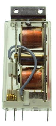
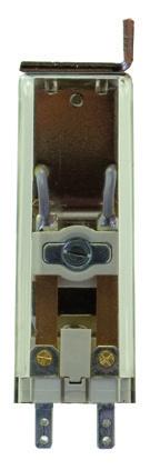
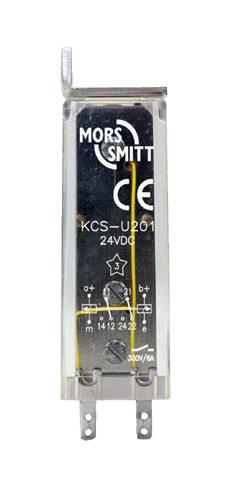
1 - Latching, 2 pole Datasheet Features Latching (bistable) relay Compact design 2 C/O contacts 2 galvanic isolated coils Weld-no-transfer contacts Flash barrier 2.8 x 0.8 faston connections Transparent cover Benefits Description Bistable railway relay with two change-over contacts. The contacts remain in the last powered position. Bistable by means of two coils and a mechanical rocker mechanism. The two separate coils are galvanically isolated. The contacts are weld-no-transfer contacts: they are mechanically forced in the same position. The KCS-U200 relay is a compact design relay connected with 2.8 x 0.8 mm fastons. The construction of the relay and choice of materials makes the KCS-U200 relay suitable to withstand low and high temperatures, shock & vibrating and dry to humid environments. Application These relay series are designed for demanding rolling stock applications. The KCS-U200 is used in applications where two contacts are used in one relay and the contacts are set and reset with permanent power or impulses. Proven reliable Long term availability Easy to maintain Low life cycle cost No maintenance Railway compliancy EN Electronic equipment used on rolling stock for railway applications IEC Electronic equipment used on railway vehicles IEC Electrical equipment for rolling stock in railway applications IEC Low voltage switch gear and control gear IEC Rolling stock equipment - Shock and vibration test IEC Electromechanical components for control applications. This standard examines both coil and contact specifications in depth EN Electromagnetic compatibility for railway applications NF F /102, EN Fire behaviour - Railway rolling stock NF F On-off contact relays and fixed connections 1


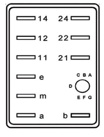
2 Functional and connection diagrams Timing diagram Relay pin correspondence Connection diagram 2
3 Coil characteristics Minimum impulse time 25 ms Operating voltage range Unom Nominal power consumption - during interval time < 1.1 W - after pulse time 25 ms Type Unom (VDC) Umin (VDC) Umax (VDC) Rcoil (Ω)* Inom (ma) KCS-U KCS-U KCS-U * ** 12 KCS-U KCS-U KCS-U Other types on request * The Rcoil is measured at room temperature and has a tolerance of ± 10% ** For 110 VDC: use KCS-U205 in series with external seriesresistor of 1800 Ω / 0.4 W Remarks: Umin is the must-operate voltage at which the relay has picked up in all circumstances (worst-case situation), in practice the relay picks up at a lower voltage Always select the nominal voltage as close as possible to the actual voltage om the application Contact characteristics Amount and type of contacts 2 C/O Maximum make current 15 A Maximum continuous current 6 A (AC1 ; IEC 60947) Maximum switching voltage 300 VDC (then max. current = 300 ma) 250 VAC (then max. current = 2.6 A) Maximum switching capacity See graph page 6 Contact resistance 15 mω (initial) Material Ag standard (optional Au on Ag) Contact gap Contact force 0.3 mm > 200 mn Note : contacts cannot have a different position (forced contacts, weld-no-transfer) 3
4 Electrical characteristics Dielectric strength EN Pole-pole IEC kv, 50 Hz, 1 min Cont-coil IEC kv, 50 Hz, 1 min Insulation between open contacts 1 kv; 50 Hz; 1 min Pulse withstanding IEC kv (1.2 / 50 μs) Mechanical characteristics Mechanical life Maximum switching frequency Weight 30 x 10 6 operations Mechanical: 3600 ops/h Electrical: 1200 ops/h 75 g Environmental characteristics Environmental EN and IEC Vibration IEC 61373, Category I, Class B, Body mounted Shock IEC 61373, Category I, Class B, Body mounted Operating temperature -25 C C (optional: -40 o C) Humidity 90 % Salt mist IEC , class ST4 Damp heat IEC , Test method Db variant 1 Protection IEC 60529, IP40 (relay on socket) Fire & smoke NF F , NF F16-102, TS Insulation materials Cover: polycarbonate Base: polyester 4
5 Dimensions (mm) 5
6 Options Code Description Remark Cannot be combined with: B Magnetic arc blow out C Low temperature (-40 C) E * Au; Gold plated contacts (10 µm) Y Double make / double break contacts 1 C/O DM/DB Keying Coil coding relay and socket Colour coding Coloured cover for coil voltage coding * Gold plated contacts characteristics Material Maximum switching voltage Maximum switching current Minimum switching voltage Minimum switching current Ag, 10 µm gold plated 60 V (higher voltages may be possible, contact Mors Smitt for more information) 400 ma (at higher rate gold will evaporate, then the standard silver contact rating of minimum 10 ma and 12 V is valid) 5 V 1 ma Also version with PCB mounting available: KCP-U200 relay 6
7 Current breaking capacity Max Switching Capacity Contact Life Watt DC 2 contacts in serie % of max switching cap. DC resistive DC inductive DC 1 contact ,10 1,00 10,00 100,00 Volt No of ops (x10 6 ) Step 1: Determine switching voltage out of the application. Step 2: Pick the maximum switching capacity (in Watt) at this voltage, out of graph maximum switching capacity. Step 3: Calculate the actual switched load (in Watt) out of the application. Step 4: Calculate the % of maximum switching capacity: Actual load Max switching capacity Step 5: Pick the life at this load out of the graph Electrical life expectancy. 7
8 Instructions Installation, operation & inspection Installation Before installation or working on the relay: disconnect the power supply first! Connect wiring according to the terminal identification. Check to ensure that the coil connection polarity is not reversed. Relays can be mounted tightly together to save space. Warning! - Never use silicon in the proximity of the relays. - Do not use the relay in the presence of flammable gas as the arc generated from switching could cause ignition. Operation After installation always apply the rated voltage to the coil to check correct operation. Before actual use of relays, it is advised to switch the load several times with the contacts. The contacts will both be electrically and mechanically cleaned due to the positive wiping action. Sometimes a contact can build up increased contact resistance (< 15 mw when new). When using silver contacts one can clean the contact by switching a contact load a few times using >24 VDC & ~2 A. Increased contact resistance is not always problematic, as it depends on circuit conditions. In general a contact resistance of 1 Ω is no problem, consult Mors Smitt for more information. Condensation in the relay is possible when the coil is energised (warm) and the outside, environmental temperature is cold. This is a normal phenomenon and will not affect the function of the relay. Materials in the relay have no hygroscopic properties. Inspection Correct operation of the relay can easily be checked as the transparent cover provides good visibility of the moving contacts. If the relay does not seem to operate correctly, check for presence of the appropriate coil voltage and polarity using a suitable multimeter. If the relay doesn t work after inspection, replace the relay unit with a similar model. Do not attempt to open the relay cover or try to repair. Contacts are calibrated and in balance, touching can affect proper operation. Also re soldering may affect correct operation. Most relay defects are caused by installation faults such as over voltage, spikes/transients, high/short current far exceeding the relay specifications. When returning the relays for investigation, please provide all information on the RMA form. Send defective relays back to the manufacturer for repair or replacement. Normal wear and tear or external causes are excluded from warranty. 8
9 Ordering scheme Configuration: KCS-U E 1. Relay model 2. Coil voltage 3. Options This example represents a KCS-U202-E Description: KCS-U200 series relay, Unom: 48 VDC, gold plated contacts 1. Relay model KCS - U2 2. Coil voltages VDC VDC VDC VDC (*) VDC VDC * can be used for 110 VDC with an external series resistor of 1800 Ω / 0.4 W 3. Options B Magnetic arc blow out C Low temperature (-40 o C) E Gold plated contacts Y Double make / double break Upon ordering indicate keying if necessary. 9


3 8544 1200 F +61 (0)3 8544 1201 E rms@rmspl.com.au (c) Copyright 2015 All rights reserved.")

10 DS-KCS-U200 V1.4 November 2016 Mors Smitt France SAS Tour Rosny 2, Avenue du Général de Gaulle, F Rosny-sous-Bois Cedex, FRANCE T +33 (0) , F +33 (0) E sales.msf@wabtec.com Mors Smitt Asia Ltd. 29/F., Fun Towers, 35 Hung To Road Kwun Tong, Kowloon, HONG KONG SAR T , F E sales.msa@wabtec.com Mors Smitt B.V. Vrieslantlaan 6, 3526 AA Utrecht, NETHERLANDS T +31 (0) , F +31 (0) E sales.msbv@wabtec.com Mors Smitt Technologies Inc Johnson Drive, Buffalo Grove, IL , USA T , F E salesmst@wabtec.com Mors Smitt UK Ltd. Graycar Business Park, Barton under Needwood, Burton on Trent, Staffordshire, DE13 8EN, UK T +44 (0) F +44 (0) E sales.msuk@wabtec.com RMS Mors Smitt Ltd. 6 Anzed Court, Mulgrave, VIC 3170, AUSTRALIA T +61 (0) F +61 (0) E rms@rmspl.com.au (c) Copyright 2015 All rights reserved. Nothing from this edition may be multiplied, or made public in any form or manner, either electronically, mechanically, by photocopying, recording, or in any manner, without prior written consent from Mors Smitt. This also applies to accompanying drawings and diagrams. Due to a policy of continuous development Mors Smitt reserves the right to alter the equipment specification and description outlined in this datasheet without prior notice and no part of this publication shall be deemed to be part of any contract for the equipment unless specifically referred to as an inclusion within such contract. Mors Smitt does not warrant that any of the information contained herein is complete, accurate, free from potential errors, or fit for any particular purpose. Mors Smitt does not accept any responsibility arising from any party s use of the information in this document.
RC-19A relay - Current monitoring
 - Current monitoring Datasheet Features AC current monitoring relay Compact design 1 C/O contact Easy installation High continuous overcurrent possible Protection against short circuit and low impedance
D4-U200 relay module - 4-pole
 D4-U200 relay module - 4-pole Datasheet Features Ultra compact space saving 4-pole relay module Easy replacement of 4-pole contactors Module consists of 4-pole relay and housing Various contact combinations
TTBCR 200 relay - Delay-on drop-out,
 - Delay-on drop-out, Datasheet instantaneous Features Delay-on drop-out and instantaneous functions Delay range from 0.5 s up to 4 s (other up to 60 s on request) Time delay fully programmable by dip switch
TDB4-U200 relay - Timer, delay-on, 4 pole
 - Timer, delay-on, 4 pole Datasheet Features Time delay relay, delay on pull-in Compact plug-in design 4 C/O contacts Delay time adjustable with a lockable knob Also available with fixed time delay Magnetic
AG 400 relay - Gold plated, 4 contacts
 - Gold plated, 4 contacts Datasheet Features Instantaneous relay Plug-in design with secure locking feature for maximum ease of maintenance 4 double make / double break C/O contacts (form Z), gold plated
BD relay - Industrial latching power
 BD relay - Industrial latching power Datasheet relay, 4 pole Features Latching (bistable) relay Compact plug-in design 2 combined coils 3 C/O contacts and N/C contact Flat, square silver plated relay pins
MTDV4-U200 relay - Voltage monitoring,
 - Voltage monitoring, Datasheet timer delay-on /-off, 4 pole Features Description Plug-in electronic voltage monitoring relay with optional delay-on and delay-off timer function and four change-over contacts.
TBSBAO 400 relay - Delay-on pull-in,
 - Delay-on pull-in, Datasheet 4 C/O Features Delay-on pull-in Delay range 50 ms...0 s Time delay fully programmable by dip switch Status LED indicator Plug-in design with secure locking feature for maximum
MTDV4 relay - Voltage monitoring,
 - Voltage monitoring, Datasheet timer delay-on /-off, 4 pole Features Description Plug-in electronic voltage monitoring relay with optional delay-on and delay-off timer function and four change-over contacts.
UBC 200 relay - Voltage monitoring
 - Voltage monitoring Datasheet Features Voltage monitoring relay 1 voltage level 2 C/O contacts, form C Plug-in design with secure locking feature for maximum ease of maintenance -40 C...+85 C operating
UTC relay - Voltage monitoring & off delay
 - Voltage monitoring & off delay Datasheet Features Voltage control time delay relay Total time delay range from 4 min to 6 min, fixed in factory 1 N/O solide state contact, 3 A Plug-in design with secure
UB 001 relay - 1 level load shedding
 - 1 level load shedding Datasheet Features Load shedding relay 1 voltage level 1 N/O solid state contact Plug-in design with secure locking feature for maximum ease of maintenance -40 C...+85 C operating
TELAU 400 relay - Delay-on pull-in or
 - Delay-on pull-in or Datasheet drop-out, 4 C/O Features Delay on pull-in or on drop-out relay Delay range 0.2 h...2 h Time delay fully programmable by dip switch Status LED indicator Plug-in design with
UB 200 relay - Voltage monitoring
 - Voltage monitoring Datasheet Features Voltage monitoring relay 1 voltage level 2 C/O contacts, form Z Plug-in design with secure locking feature for maximum ease of maintenance -40 C...+85 C operating
C relay - Safety critical, 9 contacts
 - Safety critical, 9 contacts Datasheet Features Instantaneous relay Ultra compact package size Safety-critical relay Plug-in design with secure locking feature for maximum ease of maintenance 9 double
407 relay - Latching, safety critical, 40 contacts Datasheet
 - Latching, safety critical, 40 contacts Datasheet Features Latching relay using separate coils and magnetic rocker mechanism Plug-in design with secure locking feature for maximum ease of maintenance
D-U200 Instantaneous relay Part of D-platform
 /// Plug-in railway relay with 4 C/O contacts Rugged plug-in relays for extreme reliability, within long endurance applications and harsh environments Part of D-platform Description Features Instantaneous
CM relay - 7 contacts + 2 gold contacts
 - 7 contacts + 2 gold contacts Datasheet Features Instantaneous relay For combined power & dry circuit applications in diesel locomotives 4 N/C + 5 N/O double break contacts with N/C & N/O gold bifurcated
CK relay - safety critical, 9 contacts
 - safety critical, 9 contacts Datasheet Features Instantaneous relay Safety critical relay Weld resistant Weld no transfer safety contacts standard Plug-in design with secure locking feature 9 double break
D-B Power relay, high DC breaking capacity Part of D-platform
 /// Plug-in industrial relay with 4 C/O contacts Rugged plug-in relays for extreme reliability, within long endurance applications and harsh environments D-B Power relay, high DC breaking capacity Part
MSV200 - Hall effect transducer
 - Hall effect transducer Datasheet Features Specially designed for railway applications Closed loop (compensated) High dielectric strength Precise linearity Precise accuracy High dynamic response No foucault
D Instantaneous relay Part of D-platform
 /// Plug-in industrial relay with 4 C/O contacts Rugged plug-in relays for extreme reliability, within long endurance applications and harsh environments D Part of D-platform Features Instantaneous compact
MSA Hall effect transducer
 - Hall effect transducer Datasheet Features Specially designed for railway applications losed loop (compensated) High dielectric strength Precise linearity Precise accuracy High dynamic response No foucault
MSA500 - Hall effect transducer
 - Hall effect transducer Datasheet Features Specially designed for railway applications losed loop (compensated) High dielectric strength Precise linearity Precise accuracy High dynamic response No foucault
BM 400 relay - Mixed load, 4 contacts
 - Mixed load, 4 contacts Datasheet Features Instantaneous relay Plug-in design with secure locking feature for maximum ease of maintenance double make / double break C/O silver contacts (form Z) gold bifurcated
Mors Smitt Industrial Technology. High performance plug-in relays
 Mors Smitt Industrial Technology High performance plug-in relays Power generation and distribution operators across the world rely on our relays Product range D-relays series The unique plug-in D-relay
V88 socket - Spring clamp terminal,
 REVISION V - Spring clamp terminal, Datasheet panel mount pole Features Panel / flush mount Sturdy spring clamp terminals Twin connection per relay contact Suitable for all D and KDN relay series Easy
Portable relay tester PRT-MS1 User manual
 Portable relay tester PRT-MS1 User manual www.morssmitt.com Mors Smitt B.V. Vrieslantlaan 6 3526 AA Utrecht The Netherlands Note: The performance of an electromechanical relay depends on several external
Mors Smitt Industrial Technology. Industrial current & voltage sensors. Hall effect current & voltage sensors
 Mors Smitt Industrial Technology Industrial current & voltage sensors Hall effect current & voltage sensors Mors Smitt Industrial Technology Industrial sensors Industrial current & voltage sensors Closed
Mors Smitt Railway Technology. Railway relays
 Mors Smitt Railway Technology Railway relays Mors Smitt Railway Technology Railway relays Signalling & control relays Protection relays Measuring sensors MSAV ultralight AC / DC energy measurement system
Manual Signal calibration box (SCB)
") Manual Signal calibration box (SCB) Features 35 mm rail mounting Pluggable screw connections 1 signal input 10 indicator outputs 1 NMEA0183 compatible output USB connection Scaling with Windows TM based
Manual Signal calibration box (SCB) Features 35 mm rail mounting Pluggable screw connections 1 signal input 10 indicator outputs 1 NMEA0183 compatible output USB connection Scaling with Windows TM based
Mors Smitt Industrial Technology
 Mors Smitt Industrial Technology Mors Smitt Industrial Technology Mission statement To take a leading role in industrial relay technology, installation instruments and controls and marine bridge instrumentation.
OKT OKR Series APPLICATIONS. Shipbuilding
 Timer relay 4 contacts 1.7 OKT OKR Series OVERVIEW Time setting flat head slotted screw Plug-in relay with time delay on pick-up or on drop-out Time delay setting from 0.1 second up to 1 hour Wide range
SERIES KC RELAY NONLATCH 3PDT, 25 AMP
 All welded construction Contact arrangement 3 PDT configuration in one inch cube Qualified to MIL-PRF-83536 PRINCIPLE TECHNICAL CHARACTERISTICS Applicable sockets: SO-1057-8912 Contacts rated at 28 Vdc;
2 Pole CO, 8 A Plug-in 2 CO (DPDT) 1 CO (SPDT) 8/15 16/25* 250/ /400 2,000 4, /0.5/ /0.5/ (5/5) 300 (10/5)
 1 CO (SPDT) 8/15 16/25* 250/ /400 2,000 4, /0.5/ /0.5/ (5/5) 300 (10/5)") 46 Series - Relays for railway applications 8-16 A 46 SERIES Features Plug-in power relays: 8 A, 2 pole 16 A, 1 pole Complies with EN 45545-2:2013 (protection against fire of materials), EN 61373 (resistance
46 Series - Relays for railway applications 8-16 A 46 SERIES Features Plug-in power relays: 8 A, 2 pole 16 A, 1 pole Complies with EN 45545-2:2013 (protection against fire of materials), EN 61373 (resistance
Classification Contact form Enclosure rating Terminal shapes Model Minimum packing unit Standard. SPST-NO (1a) Fully sealed PCB terminal
 Fully sealed PCB terminal") SPST Slim Power Relay for A switching Slim -mm width and miniature size. (20.08 12. mm) High switching capability A (20 VAC and VDC), and high contact reliability by crossbar-twin contact. Low power consumption
SPST Slim Power Relay for A switching Slim -mm width and miniature size. (20.08 12. mm) High switching capability A (20 VAC and VDC), and high contact reliability by crossbar-twin contact. Low power consumption
Nieaf-Smitt Maritime. Analogue panel indicators
 Nieaf-Smitt Maritime Analogue panel indicators Nieaf-Smitt Maritime Analogue panel indicators Reliable indication is vital in all use Nieaf-Smitt Maritime technology Company NIF (Netherlands Instrumentation
Type Nominal voltage (V) Code HSV V
 Code HSV V") Speed control Speed control relay - mm Control of overspeed, underspeed, operating rate, stopping Measurement via discrete sensors - -wire PNP or NPN, Namur, voltage 0-0V or volt-free contact type Works
Speed control Speed control relay - mm Control of overspeed, underspeed, operating rate, stopping Measurement via discrete sensors - -wire PNP or NPN, Namur, voltage 0-0V or volt-free contact type Works
 Phase control Single function phase control relay - 7.5 mm Control of -phase networks: phase sequence, total phase failure Multi-voltage from x 08 to x 480 V Controls its own supply voltage True RMS measurement
MINIATURE POWER RELAY IN DS RELAY SERIES FEATURES resistance ORDERING INFORMATION. Ex. DSP 1 L DC12V R
 MINIATURE POWER RELAY IN DS RELAY SERIES DSP- RELAYS DSPa DSP SPECIFICATIONS.. DSPa Coil (polarized) (at C F) Minimum mw power coil latching mw mw power coil latching mw.... Contact Arrangement a ab a
Ordering Information. PCB Relay G6RL. Model Number Legend: Low-profile power relay with maximum switching of 10 A
 PCB Relay G6RL Low-profile power relay with maximum switching of 10 A Low profile: 12.3 mm in height Max. switching capacity: 2,500 VA (NO) IEC 60947-5-1, AC-15, DC13 Clearance and creepage distance: 10
27/04/2015
 Modular Carril DIN 35 mm HIL Part number 84871120 Control of AC and DC currents Automatic recognition of AC/DC Measurement ranges from 2 ma to 10 A Choice between over and undercurrent True RMS measurement
22 Series Relays. Technical Data...1. Specifications...2. Model Number Structure - Relays...3. Model Number Selection
 Relays 22 Technical Data...1 Specifications...2 Model Number Structure - Relays...3 Model Number Selection... 4-5 Electrical Characteristics...6 Accessories...7 Dimensions...8 Instructions...10 Safety
RF Signal Relays AXICOM. HF3 Relay
 HF3 Relay n Y-Design n Frequency range DC to 3GHz n Impedance 50Ω or 75Ω n Small dimensions (14.6x7.2x10mm) n 1 form C contact (1 changeover contact) n Immersion cleanable n Low power consumption ( 140mW)
PCB Relay. Ordering Information. SPST-NO Type Breaks 10-A Loads; SPST-NO + SPST-NC Type Breaks 8-A Load
 PCB Relay SPST-NO Type Breaks 10-A Loads; SPST-NO + SPST-NC Type Breaks -A Load Compact: 20 x 15 x 10 mm (L x W x H). Low power consumption: 200 mw. Flux protection or plastic-sealed construction available.
PCB Relay SPST-NO G6CU-1117P-US G6CU-1114P-US G6CU-1117C-US G6CU-1114C-US SPST-NO + SPST- G6CU-2117P-US G6CU-2114P-US G6CU-2117C-US G6CU-2114C-US
 PCB Relay SPST-NO Type Breaks 10-A Loads; SPST-NO + SPST-NC Type Breaks 8-A Load Compact: 20 15 10 mm (L W H). Low power consumption: 200 mw. Flux protection or fully sealed construction available. Unique
3. Contact Form A: SPST-NO
 0 A Compact and high power latching relay High power switching: 0 A, 6 VAC Compact size: mm mm mm Low temperature-rise High overcurrent capability, conforming to IEC6055- UC RoHS Compliant Model Number
POWER RELAY. FTR-K3-WS Series. 1 POLE - High Capacity 25A Type FTR-K1 SERIES FEATURES
 POWER RELAY 1 POLE - High Capacity 25A Type FTR-K3-WS Series FEATURES 1 pole, 25A 1 form A contact Wide contact gap: 1.8mm Dielectric strength (B/T open contacts) 2.5kV Compliant with European photovoltaic
PCB relay for DC voltage, polarized, monostable or bistable
 V23042 PCB relay for DC voltage, polarized, monostable or bistable Features Universally applicable in the most varied circuit functions in the field of telecommunications and small signal technology Versatile
YL SERIES RELAY LATCH DC COIL 4PDT, LOW LEVEL TO 5 AMP
 Magnetic latch operation All weld construction Contact arrangement 4 PDT Qualified to MIL-PRF-6106 PRINCIPLE TECHNICAL CHARACTERISTICS Applicable sockets: SO-1066-001 SM-1002-003 Contacts rated at Low
Ref: HLSR 10-P/SP3, HLSR 20-P/SP3, HLSR 40-P/SP3, HLSR 50-P/SP3
 Current Transducer HLSR-P/SP3 series N = 10... 50 A Ref: HLSR 10-P/SP3, HLSR 20-P/SP3, HLSR 40-P/SP3, HLSR 50-P/SP3 For the electronic measurement of current: DC, AC, pulsed..., with galvanic separation
SLIM COMPACT SAFETY RELAY
 SLIM COMPACT SAFETY RELAY SF-RELAYS Slim type Max. 24.945 Max. 24.945 Max. 4.575 Max. 5.969 Max. 3.52 Max. 3.52 mm inch FEATURES Forcibly guide contact structure (EN525 ClassA TÜV recognized) Slim profile
PCB Relay. Contact form Terminal Single-side stable Single-winding latching Double-winding latching
 PCB Relay Subminiature, Sensitive SPDT Signal Switching Relay High sensitivity: 98-mW pickup coil power. Impulse withstand voltage meets FCC Part 68 requirements. Fully sealed construction. Unique moving
LOW-PROFILE SURFACE-MOUNT RELAY. Characteristics. Initial breakdown voltage. Initial surge voltage. Temperature rise* 2 (at 20 C) Max.
 Max.") TESTING LOW-PROFILE SURFACE-MOUNT RELAY RELAYS 5.6. mm inch FEATURES Low-profile: 6 mm.36 inch in height comforming to EIA standards (Tape height: max. 6.5 mm.56 inch ) Tape and reel package is available
TESTING LOW-PROFILE SURFACE-MOUNT RELAY RELAYS 5.6. mm inch FEATURES Low-profile: 6 mm.36 inch in height comforming to EIA standards (Tape height: max. 6.5 mm.56 inch ) Tape and reel package is available
Classification Enclosure rating Contact form Model Standard Flux protection SPST-NO G6RL-1A
 PCB Relay Low-profile power relay with maximum switching of 8 A Low profile: 12.3 mm in height Max. switching capacity: 2,500 VA (NO) Dielectric strength: 5 kv Clearance and creepage distance: 10 mm. RoHS
G6C. Miniature High Capacity Relays with SPST-NO 10A and SPST-NO + SPST-NC 8A. Model Number Legend. Application Examples.
 Miniature High Capacity Relays with SPST-NO 0A and SPST-NO + SPST-NC A SPST-NO 0A and SPST-NO + SPST-NC A for power switching and output that satisfy the needs for space-saving. Small High-capacity Relays
Relion 605 series Self-Powered Feeder Protection REJ603 Product Guide
 Relion 605 series Relion 605 series Self-Powered Feeder Protection Product Guide Contents 1 Description...3 2 Protection functions...3 3 Application...4 4 Self-supervision...4 5 Inputs and outputs...4
Mors Smitt Industrial Technology
 Mors Smitt Industrial Technology Mors Smitt Industrial Technology Designers, manufacturers & sup instrumentation and electronic con for de Industry Heavy duty relays General purpose relays Time delay
Low profile safety relay with forcibly guided double contacts FEATURES. Relay height, 14.5mm. 4a2b
 Low profile safety relay with forcibly guided double contacts SFN4D RELAY 3.3 33.0 FEATURES Relay complies with EN 020, Type B. Polarized magnet system with snap action function Tolerance ±0.3 mm Weight
AC/DC Current Probe GCP-100 QUICK START GUIDE ISO-9001 CERTIFIED MANUFACTURER
 AC/DC Current Probe GCP-100 QUICK START GUIDE ISO-9001 CERTIFIED MANUFACTURER This manual contains proprietary information, which is protected by copyright. All rights are reserved. No part of this manual
Reyrolle Protection Devices. 7PG21 Solkor R/Rf Pilot Wire Current Differential Protection. Answers for energy
 Reyrolle Protection Devices 7PG21 Solkor R/Rf Pilot Wire Current Differential Protection Answers for energy 7PG21 Solkor R/Rf Pilot Wire Current Differential Protection Additional Options 15kV Isolation
Compact size 2 Form A and 2 Form A 1 Form B 35A power relays for energy management and industrial equipment. Conditions. Mirror contact mechanisms
 Compact size and 3A power relays for energy management and industrial equipment HE-S RELAYS New TYPICAL APPLICATIONS Photovoltaic power generation systems (Solar inverter) Uninterruptible Power Supplies
To be Discontinued FBR46 SERIES. MINIATURE RELAY 2 POLES 1 to 2 A (FOR SIGNAL SWITCHING) RoHS compliant FEATURES
 RoHS compliant FEATURES") MINIATURE RELAY 2 POLES 1 to 2 A (FOR SIGNAL SWITCHING) FBR46 SERIES RoHS compliant FEATURES Miniature size About 50% smaller in volume compared with the FBR240 series used mainly in communication equipment.
MINIATURE RELAY 2 POLES 1 to 2 A (FOR SIGNAL SWITCHING) FBR46 SERIES RoHS compliant FEATURES Miniature size About 50% smaller in volume compared with the FBR240 series used mainly in communication equipment.
Power PCB Relay. To Order: Select the part number and add the desired coil voltage rating (e.g., G6B-1114-US-DC6).
.") Power PCB Relay Subminiature 20 L x 9.90 W x 9.90 H mm (0.79 L x 0.39 W x 0.39 H in) Low power consumption (200 mw) Sealed construction permits automatic soldering and cleaning of the PC board High-capacity
Power PCB Relay Subminiature 20 L x 9.90 W x 9.90 H mm (0.79 L x 0.39 W x 0.39 H in) Low power consumption (200 mw) Sealed construction permits automatic soldering and cleaning of the PC board High-capacity
Ordering Information. Latching Relay MMK. Available Models. Models Conforming to Auxiliary Power Relay Specifications
 Latching Relay MMK CSM_MMK_DS_E_1_1 Mechanically Latching Relays Based on the MM Power Relay Low power consumption due to mechanical latch for economic operation. Relays with mixed coil specifications
C20.en. Power contactors for AC and DC CT1115 and CT1130. Connect - Contact - Control
 Caution: Device contains unprotected active pieceparts, Device contains unprotected non-active pieceparts, which may interact with active pieceparts, Touch only after adhering to corresponding safety regulations!
I P. /dt. di p V S+ Applications. Standards. 1) IEC ed1.0: 2007; IEC : ed1.0: 2012
 IEC ed1.0: 2007; IEC : ed1.0: 2012") Ref: ART-B22-D70, ART-B22-D125, ART-B22-D175 Flexible clip-around Rogowski coil for the electronic measurement of AC current with galvanic separation between the primary circuit (power) and the secondary
Ref: ART-B22-D70, ART-B22-D125, ART-B22-D175 Flexible clip-around Rogowski coil for the electronic measurement of AC current with galvanic separation between the primary circuit (power) and the secondary
For the electronic measurement of current: DC, AC, pulsed..., with galvanic separation between the primary and the secondary circuit.
 Current Transducer HO-NP series I PN = 4, 6, 12, 15 Ref: HO 4-NP, HO 6-NP, HO 12-NP, HO 15-NP For the electronic measurement of current: DC, C, pulsed..., with galvanic separation between the primary and
I P. /dt. di p V S Applications. Standards 1) IEC : 2007; IEC : ) IEC : 2016; IEC : 2017
 IEC : 2007; IEC : ) IEC : 2016; IEC : 2017") Ref: ART-B22-D70, ART-B22-D125, ART-B22-D175, ART-B22-D300 Flexible clip-around Rogowski coil for the electronic measurement of AC current with galvanic separation between the primary circuit (power) and
Ref: ART-B22-D70, ART-B22-D125, ART-B22-D175, ART-B22-D300 Flexible clip-around Rogowski coil for the electronic measurement of AC current with galvanic separation between the primary circuit (power) and
2 pole (1 NO + 1 NC) 1 NO + 1 NC 2 NO + 2 NC, 3 NO + 1 NC 4 NO + 2 NC Rated current / Max. peak current Rated load AC1
 1 NO + 1 NC 2 NO + 2 NC, 3 NO + 1 NC 4 NO + 2 NC Rated current / Max. peak current Rated load AC1") Features 7S.12...5110 7S.14...0220/0310 7S.16..0420 Relay module with forcibly guided contacts 7S.12 with 2 pole (1NO + 1 NC) 7S.14 with 4 pole (2 NO + 2 NC and 3 NO + 1 NC) 7S.16 with 6 pole (4 NO + 2
Features 7S.12...5110 7S.14...0220/0310 7S.16..0420 Relay module with forcibly guided contacts 7S.12 with 2 pole (1NO + 1 NC) 7S.14 with 4 pole (2 NO + 2 NC and 3 NO + 1 NC) 7S.16 with 6 pole (4 NO + 2
Relays & Sockets. RF1V Force Guided Relays/SF1V Relay Sockets. Certification Organization/ File Number. UL/c-UL File No.
 RFV Key features: Compact and EN compliant RFV force guided relays Force guided contact mechanism (EN00 Type A TÜV approved) Contact configuration -pole (NO-NC, 3NO-NC) 6-pole (NO-NC, NO-NC, 3NO-3NC) Built-in
60 Series - General purpose relays 6-10 A. Features Plug-in mount 10 A General purpose relay
 Series - General purpose relays - 0 A Features Plug-in mount 0 A General purpose relay.. & pole changeover contacts Cadmium Free contacts (preferred version) AC coils & DC coils UL Listed (certain relay/socket
AXICOM Telecom-, Signal and RF Relays. FX2 Relay Nov. 07 Rev. E ECOC: JM10
 108-98003 Nov. 07 Rev. E ECOC: JM10 Disclaimer While Tyco Electronics has made every reasonable effort to ensure the accuracy of the information in this datasheet, Tyco Electronics does not guarantee that
Classification Enclosure rating Contact form Contact material
 PCB Relay Low-profile power relay with maximum switching of 10 A Low profile: 12.3 mm in height Max. switching capacity: 2,500 VA (NO) Dielectric strength: 5 kv Clearance and creepage distance: 10 mm.
AXICOM Telecom-, Signal and RF Relays. D2n V23105 Relay Nov. 07 Rev A ECOC: JM10
 108-98007 Nov. 07 Rev A ECOC: JM10 Disclaimer While Tyco Electronics has made every reasonable effort to ensure the accuracy of the information in this datasheet, Tyco Electronics does not guarantee that
POWER RELAY. FTR-K3-WG Series. 1 POLE - 25A - 1.5mm contact gap FTR-K1 SERIES FEATURES
 FTR-K1 SERIES POWER RELAY 1 POLE - 25A - 1.5mm contact gap FTR-K3-WG Series FEATURES 1 pole, 25A 1 Form A Contact gap 1.5mm Surge strength (B/T open contacts) 2.5kV Compliance with European photovoltaic
MT4 Relay. 4 pole telecom/signal relay Through Hole Type (THT) Non-polarized. non-latching 1 coil. Features. Typical applications
 Non-polarized. non-latching 1 coil. Features. Typical applications") 4 pole telecom/signal relay Through Hole Type (THT) Non-polarized. non-latching 1 coil Features Telecom/signal relay (dry circuit, test access, ringing) 20 x 14.8 mm, 0.795 x 0.582 inch Switching current
4 pole telecom/signal relay Through Hole Type (THT) Non-polarized. non-latching 1 coil Features Telecom/signal relay (dry circuit, test access, ringing) 20 x 14.8 mm, 0.795 x 0.582 inch Switching current
COMPACT HIGH POWER RELAY
 COMPACT HIGH POWER RELAY For automotive applications POLE - 6A (For 2V Car Battery) FBR59-HW Series FEATURES pole, 6A, form U High temperature grade (-4 C to 25 C) Comparable capability with Power Mini
G5Q. Ordering Information. Specifications. PCB Relay. Compact, High Isolation Relay J COIL RATINGS. 638 PCB Relay G5Q
 PCB Relay G5Q Compact, High Isolation Relay D Compact single pole relay with high isolation between coil and contacts. D Up to 10 A switching on the NO contacts. D Ensures a withstand impulse voltage of
PART NUMBERING SYSTEM
 Plug-In Timer pins Multifunction or monofunction Compact body for space saving Wide time range (from 0. seconds to 0 days delay) niversal power supply (-0 Vz) or relay outputs (SPDT / Changeover) Protective
1 POLE - 1 to 2A (For Signal Switching)
") MINIATURE RELAY 1 POLE - 1 to A (For Signal Switching) SY Series FEATURES Very small size and light weight UL, CSA recognized Conforms to FCC rules and regulations part 68 Dielectric strength 00 VAC between
MINIATURE RELAY 1 POLE - 1 to A (For Signal Switching) SY Series FEATURES Very small size and light weight UL, CSA recognized Conforms to FCC rules and regulations part 68 Dielectric strength 00 VAC between
ULTRA LOW PROFILE 2 A POLARIZED RELAY. mm inch. Initial breakdown voltage
 TESTING ULTRA LOW PROFILE POLARIZED RELAY RELAYS 9...7 mm inch FEATURES Low profile mm.7 inch height High contact capacity: Surge withstand between contact and coil:, V (Telcordia) RoHS Directive compatibility
Ref: HLSR 10-SM, HLSR 16-SM, HLSR 20-SM, HLSR 32-SM, HLSR 40-SM, HLSR 50-SM
 Current Transducer HLSR-SM series N = 1... 5 A Ref: HLSR 1-SM, HLSR 16-SM, HLSR 2-SM, HLSR 32-SM, HLSR 4-SM, HLSR 5-SM For the electronic measurement of current: DC, AC, pulsed..., with galvanic separation
MK-S (New Models) General-purpose Relays. New Super MK Relays. Models with Latching Lever Added to the Series. Features. Model Number Structure
 General-purpose Relays. New Super MK Relays. Models with Latching Lever Added to the Series. Features. Model Number Structure") General-purpose Relays MK-S (New Models) CSM_MK-S_DS_E New Super MK Relays. Latching Lever Added to the Series. Same mounting and internal wiring as the previous Super MK Relays Built-in mechanical indicator
General-purpose Relays MK-S (New Models) CSM_MK-S_DS_E New Super MK Relays. Latching Lever Added to the Series. Same mounting and internal wiring as the previous Super MK Relays Built-in mechanical indicator
Introducing. CII FCA-150 Series Relay 50 Amps, 1PST/NO (DM) CII FCAC-150 Series Relay 50 Amps, 1PST/NO (DM) with 1PDT Auxiliary Contacts
 CII FCAC-150 Series Relay 50 Amps, 1PST/NO (DM) with 1PDT Auxiliary Contacts") Introducing CII Series Relay 50 Amps, 1PST/NO (DM) CII Series Relay 50 Amps, 1PST/NO (DM) with 1PDT Auxiliary Contacts Key Features Non-latching relay Balanced force design Corrosion protected metal enclosure
Introducing CII Series Relay 50 Amps, 1PST/NO (DM) CII Series Relay 50 Amps, 1PST/NO (DM) with 1PDT Auxiliary Contacts Key Features Non-latching relay Balanced force design Corrosion protected metal enclosure
2 PDT Coil supply. Contacts rated at. Contact rating per pole and load type. Load Current in 100,000 cycles 100,000 cycles
 ENGINEERING DATA SHEET GP250 RELAY - LATCH 2 PDT, 2 AMP Polarized, latching hermetically sealed relay Contact arrangement 2 PDT Coil supply Direct current Qualified to SCC3602/010 PRINCIPLE TECHNICAL CHARACTERISTICS
HIGH VOLTAGE AND CURRENT CUT-OFF CAPACITY IN A COMPACT PACKAGE FEATURES
 HIGH VOLTAGE AND CURRENT CUT-OFF CAPACITY IN A COMPACT PACKAGE (60A type only) RELAYS A PC board type 80A Connector type 60A Screw terminal type A TM type 300A Connector type RoHS Directive compatibility
MK-S (New Models) General-purpose Relays. New Super MK Relays. Models with Latching Lever Added to the Series. Features. Model Number Structure
 General-purpose Relays. New Super MK Relays. Models with Latching Lever Added to the Series. Features. Model Number Structure") General-purpose Relays MK-S (New Models) CSM_MK-S_DS_E 1 New Super MK Relays. Latching Lever Added to the Series. Same mounting and internal wiring as the previous Super MK Relays Built-in mechanical indicator
General-purpose Relays MK-S (New Models) CSM_MK-S_DS_E 1 New Super MK Relays. Latching Lever Added to the Series. Same mounting and internal wiring as the previous Super MK Relays Built-in mechanical indicator
Classification Terminal Shape Contact form Enclosure rating Model Rated coil voltage
 ow-profile Relay with Various Models ow profile:.7 mm in height. Creepage distance 8mm between coil and contacts 0 kv Impulse withstand voltage Models with AC coil available. High-Inrush model available
Model Number Structure
 General-purpose Relay MK-I/-S Electromechanical Relays Exceptionally Reliable General-purpose Relay Features Mechanical Indicator/Push Button Breaks relatively large load currents despite small size. Long
 Distributed by: www.jameco.com 1-8-81-44 The content and copyrights of the attached material are the property of its owner. SLIM POLARIZED RELAY TN RELAYS.551. 9.8.86 FEATURES Small header area makes higher
OMRON MK-I / -S RELAY
 Issued April 0 0 DATA SHEET OMRON MK-I / -S RELAY Based on OMRON Datasheet General-purpose Relay MK-I/-S 0 Exceptionally Reliable General-purpose Relay Features Mechanical Indicator/Push Button Breaks
Zelio Control Measurement Relays
 Selection Guide Application Voltage control Current control Functions 3-phase Single-phase and d.c. Integrated current transformer - Overvoltage and between phases - Overvoltage and between phases and
Ref: HLSR 10-SM/SP33, HLSR 20-SM/SP33, HLSR 32-SM/SP33, HLSR 40-P/SP33, HLSR 50-SM/SP33
 Current Transducer HLSR-SM/SP33 series I PN = 10... 50 A Ref: HLSR 10-SM/SP33, HLSR 20-SM/SP33, HLSR 32-SM/SP33, HLSR 40-P/SP33, HLSR 50-SM/SP33 For the electronic measurement of current: DC, AC, pulsed...,
40 Series - Miniature P.C.B. Relays A
 ..4..4..4 40 Series - Miniature P.C.B. Relays 8-0 - 6 A - P.C.B. or plug-in mount - AC, DC, sensitive DC or single bistable coil versions available - 8 mm, 6 kv (./0 µs) between coil and contacts - Ambient
RISH EM 3490 SS Kilowatt Hour Energy Meter With Rs485 RISH EM 3490 SS. Application : Product Features: Indication: Pulse Indication:
 Application : RISH Master 3490 SS is a 96mm x 96mm panel mounted kilowatt hour meter it measures active energy with class 1.0 accuracy having auto-resetting 8 digit seven segment LED counter. The unit
Type Poles Contact configuration Rated voltage Model G7S-4A2B 24 VDC 3PST-NO, 3PST-NC
 Relays with Forcibly Guided Contacts G7S CSM_G7S_DS_E_5_ Relays Conforming to EN Standard Relays with forcibly guided contacts (EN50205 Class A, certified by VDE). Supports the CE marking of machinery
3.5 mm contact pin pitch 1 Pole 12 A PCB direct or via socket
 8-12 - 16 A Features 41.31 41.52 41.61 1 & 2 Pole - Low profile (15.7 mm height) 41.31-1 Pole 12 A (3.5 mm pin pitch) 41.52-2 Pole 8 A (5 mm pin pitch) 41.61-1 Pole 16 A (5 mm pin pitch) PCB mount - direct
SPST-NO SPDT DPST-NO DPDT
 PCB Relay A Power Relay with Various Models High-sensitivity ( mw) and High-capacity ( A) Models available. Low profile:.7 mm max. in height Conforms to VDE (EN0-), UL and CSA.. Meets EN0- requirements
SPAC265-8W. AC-DC power supply module. Features. Description. Applications
 AC-DC power supply module Datasheet production data Features Open frame switch mode power supply European input voltage range Single output 5 V, 8 W peak power, 4 W continuous operating mode EMC compliance