ELG4139: DC to AC Converters
|
|
|
- Barrie Patrick
- 6 years ago
- Views:
Transcription
 output.")
1 ELG4139: DC to AC Converters Converts DC to AC power by switching the DC input voltage (or current) in a pre-determined sequence so as to generate AC voltage (or current) output. I DC I ac + + V DC V ac
2 Harmonics Filtering DC SUPPLY INVERTER (LOW PASS) FILTER LOAD L + v O 1 C + v O 2 BEFORE FILTERING AFTER FILTERING v O 1 v O 2 Output of the inverter is chopped AC voltage with zero DC component. It contain harmonics. An LC section low-pass filter is normally fitted at the inverter output to reduce the high frequency harmonics. In some applications such as UPS, high purity sine wave output is required. Good filtering is a must. In some applications such as AC motor drive, filtering may not required.
3 Single Phase Half-Bridge Inverter V dc + V C1 - V C2 + - G V o R L S 1 + S 2 Vdc 2 0 Vdc 2 S1 ON S2 OFF S1 OFF S2 ON t Also known as the Inverter Leg! Both capacitors have the same value. Thus the DC link is equally spilt into two. The top and bottom switch has to be complementary. Meaning, If the top switch is closed (ON), the bottom must be OFF, and vice-versa.
4 Q 1 on, Q 2 off, v o = V s /2 Peak Reverse Voltage of Q 2 = V s
5 Q 1 off, Q 2 on, v o = -V s /2
6 Single Phase Full Bridge V RG + LEG R LEG R' V dc 2 p 2p wt + V dc - V dc 2 - G S1 R + V o - S3 R' V R ' G V dc 2 V dc 2 p 2p wt + V dc 2 - S4 S2 V dc 2 V o V dc Vo = V V RG R ' G G is "virtual groumd" p 2p wt V dc Single phase full bridge is built from two half-bridge leg. The switching in the second leg is delayed by 180 degrees from the first leg.
7 Q 1 -Q 2 on, Q 3 -Q 4 off, v o = V s + V s -
8 Q 3 -Q 4 on, Q 1 -Q 2 off, v o = -V s - V s +
9 Performance Parameters Harmonic factor of the nth harmonic (HF n ) HF n V on = for n>1 V o1 V on = rms value of the nth harmonic component V 01 = rms value of the fundamental component Total Harmonic Distortion (THD): Measures the closeness in shape between a waveform and its fundamental component THD 1 = ( V ) V o1 n= 2,3, on
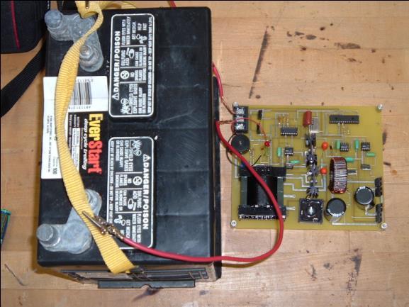
10 Design Constraints of a Pure Sine wave Inverter Quantity Voltage Details Convert 12VDC to 120 VAC Power Provide 300 W continuous Efficiency Waveform Total Harmonic Distortion > 90% efficiency Pure 60 Hz sinusoidal < 5% THD Physical Dimensions 8 x 4.75 x 2.5 Cost $175.00
11 Required Components for Design 12 V DC Input from vehicle battery) PWM Control Circuit Half-bridge Converter Transformer Low-pass Filter 120 VAC, 60 Hz, 300 W Output Full-bridge Inverter Sinusoidal PWM Controller
12 PWM Controller Produces two complementary pulses to control half-bridge transistors. Problem: Voltage may drop when the input voltage is decreased. Solution: A feedback network may be added for voltage regulation.
13 Pulse Width Modulation h( x) = if( k( x) c( x) 1 if( k( x) c( x) 1 0) ) 1 +1 M 1 0 Modulating Waveform Carrier waveform t 1 t 2 Sinusoidal modulating waveform, v m (t) p Carrier, v c (t) 2p t 1 V dc 2 t' 1 t' 2 Regular sampling waveform, v s (t) 0 V dc 2 t0 t1 t t 2 3 t t 4 5 v pwm t Regular sampling PWM Triangulation method (Natural sampling). Amplitudes of the triangular wave (carrier) and sine wave (modulating) are compared to obtain PWM waveform. Analogue comparator may be used. Basically an analogue method. Its digital version, known as REGULAR sampling is widely used in industry.
14 Software Flow Diagram (Dr. Yaroslav Koshka) Initialize all variables Count0 = 300 (300 duty cycles) no 300 duty cycle values? yes Output 1 = high, Output 2 = low duty cycle table (increment pointer) Duty cycle and sampling period timer Output 1 = low, Output 2 = high Decrement Count0 by 1 no Has duty cycle been reached? yes no One Sampling Period? ye s

15 Low-pass Filter 2 nd order L-C filter Filters to retain a 60 Hz fundamental frequency Few components Handle current Wind inductor (fine tune)

16 PCB Layout

17 Case Study: Solar System Using Inverters Stand Alone; Simple Grid Tied; Grid Tie with Battery Solar Schoolhouse and San Mateo College
18
19


20 Simple Grid-Connected System Utility Solar Array Inverter Distribution Panel

21 Subpanel Solar AC in from Inverter Lightning surge arrestor
22
23 Stand Alone Residential System Solar Array Charge Controller DC to AC Inverter Distribution Panel AC Battery Distribution Panel DC

24 Small Stand Alone System Solar Array (to power an office) Charge Control Storage: Battery Fuel Gauge Inverter DC to AC
Lecture Note. DC-AC PWM Inverters. Prepared by Dr. Oday A Ahmed Website: https://odayahmeduot.wordpress.com
 Lecture Note 10 DC-AC PWM Inverters Prepared by Dr. Oday A Ahmed Website: https://odayahmeduot.wordpress.com Email: 30205@uotechnology.edu.iq Scan QR DC-AC PWM Inverters Inverters are AC converters used
CHAPTER 5 MODIFIED SINUSOIDAL PULSE WIDTH MODULATION (SPWM) TECHNIQUE BASED CONTROLLER
 TECHNIQUE BASED CONTROLLER") 74 CHAPTER 5 MODIFIED SINUSOIDAL PULSE WIDTH MODULATION (SPWM) TECHNIQUE BASED CONTROLLER 5.1 INTRODUCTION Pulse Width Modulation method is a fixed dc input voltage is given to the inverters and a controlled
74 CHAPTER 5 MODIFIED SINUSOIDAL PULSE WIDTH MODULATION (SPWM) TECHNIQUE BASED CONTROLLER 5.1 INTRODUCTION Pulse Width Modulation method is a fixed dc input voltage is given to the inverters and a controlled
14. DC to AC Converters
 14. DC to AC Converters Single-phase inverters: 14.1 Single-phase half-bridge inverter This type of inverter is very simple in construction. It does not need output transformer like parallel inverter.
13. DC to AC Converters
 13. DC to AC Converters Inverters Inverter is a device which converts DC voltages (or current) to AC voltages (or current).inverter converting voltage is called VOLTAGE SOURCE INVERTER (VSI), while inverter
Lecture 19 - Single-phase square-wave inverter
 Lecture 19 - Single-phase square-wave inverter 1. Introduction Inverter circuits supply AC voltage or current to a load from a DC supply. A DC source, often obtained from an AC-DC rectifier, is converted
CHAPTER 3 SINGLE SOURCE MULTILEVEL INVERTER
 42 CHAPTER 3 SINGLE SOURCE MULTILEVEL INVERTER 3.1 INTRODUCTION The concept of multilevel inverter control has opened a new avenue that induction motors can be controlled to achieve dynamic performance
Pulse width modulated (PWM) inverters are mostly used power electronic circuits in
 inverters are mostly used power electronic circuits in") 2.1 Introduction Pulse width modulated (PWM) inverters are mostly used power electronic circuits in practical applications. These inverters are able to produce ac voltages of variable magnitude and frequency.
2.1 Introduction Pulse width modulated (PWM) inverters are mostly used power electronic circuits in practical applications. These inverters are able to produce ac voltages of variable magnitude and frequency.
Micro-controller Based Three-phase Voltage Source Inverter for Alternative Energy Source. Abstract
 Micro-controller Based Three-phase Voltage Source Inverter for Alternative Energy Source M.M. A. Rahman, Kurt Hammons, Phillip Beemer, Marcia Isserstedt, and Matt Trommater School of Engineering Padnos
MATLAB Implementation of a Various Topologies of Multilevel Inverter with Improved THD
 2016 IJSRSET Volume 2 Issue 3 Print ISSN : 2395-1990 Online ISSN : 2394-4099 Themed Section: Engineering and Technology MATLAB Implementation of a Various Topologies of Multilevel Inverter with Improved
CHAPTER 7 MAXIMUM POWER POINT TRACKING USING HILL CLIMBING ALGORITHM
 100 CHAPTER 7 MAXIMUM POWER POINT TRACKING USING HILL CLIMBING ALGORITHM 7.1 INTRODUCTION An efficient Photovoltaic system is implemented in any place with minimum modifications. The PV energy conversion
Lecture 20. Single-phase SPWM inverters
 Lecture 20. Single-phase SPWM inverters 20.1 Sinusoidal Pulse Width Modulation (SPWM) In this scheme a sinusoidal modulating voltage ec of the desired output frequency f o is compared with a higher frequency
International Journal of Advance Engineering and Research Development
 Scientific Journal of Impact Factor (SJIF): 4.14 International Journal of Advance Engineering and Research Development Volume 3, Issue 10, October -2016 e-issn (O): 2348-4470 p-issn (P): 2348-6406 Single
Cascaded H-Bridge Multilevel Inverter
 I J C T A, 9(7), 2016, pp. 3029-3036 International Science Press ISSN: 0974-5572 Cascaded H-Bridge Multilevel Inverter Akanksha Dubey* and Ajay Kumar Bansal** ABSTRACT This paper Presents design and simulation
DESIGN AND IMPLEMENTATION OF SINGLE PHASE INVERTER
 DESIGN AND IMPLEMENTATION OF SINGLE PHASE INVERTER PROF. A. N. WADEKAR, abhijitwadekar69@gmai.com J B BANDGAR, bandgarjayshri3@gmail.com S V JADHAV swapnalij1996@gmail.com U.S MANE, ulkamane@gmail.com
International Journal of Advance Engineering and Research Development
 Scientific Journal of Impact Factor (SJIF): 4.72 International Journal of Advance Engineering and Research Development Volume 4, Issue 8, August -2017 e-issn (O): 2348-4470 p-issn (P): 2348-6406 Analysis
Comparison of SPWM,THIPWM and PDPWM Technique Based Voltage Source Inverters for Application in Renewable Energy
 Comparison of SPWM,THIPWM and PDPWM Technique Based Voltage Source Inverters for Application in Renewable Energy Lokesh Chaturvedi, D. K. Yadav and Gargi Pancholi Department of Electrical Engineering,
Simulation of Three Phase Cascaded H Bridge Inverter for Power Conditioning Using Solar Photovoltaic System
 Simulation of Three Phase Cascaded H Bridge Inverter for Power Conditioning Using Solar Photovoltaic System 1 G.Balasundaram, 2 Dr.S.Arumugam, 3 C.Dinakaran 1 Research Scholar - Department of EEE, St.
Experiment 4: Three-Phase DC-AC Inverter
 1.0 Objectives he University of New South Wales School of Electrical Engineering & elecommunications ELEC4614 Experiment 4: hree-phase DC-AC Inverter his experiment introduces you to a three-phase bridge
Experimental Implementation of a Low-Cost Single Phase Five-Level Inverter for Autonomous PV System Applications Without Batteries
 Engineering, Technology & Applied Science Research Vol. 8, No. 1, 2018, 2452-2458 2452 Experimental Implementation of a Low-Cost Single Phase Five-Level Inverter for Autonomous PV System Applications Without
Ch.8 INVERTER. 8.1 Introduction. 8.2 The Full-Bridge Converter. 8.3 The Square-Wave Inverter. 8.4 Fourier Series Analysis
 Ch.8 INVERTER 8.1 Introduction 8.2 The Full-Bridge Converter 8.3 The Square-Wave Inverter 8.4 Fourier Series Analysis 8.5 Total Harmonic Distortion 8.6 PSpice Simulation of Square-Wave Inverters 8.7 Amplitude
International Journal of Engineering Trends and Technology (IJETT) Volume 5 Number 7- Nov 2013
 Volume 5 Number 7- Nov 2013") Voltage Balancing Control of Neutral-Point Clamped Inverters Using Multi Carrier Pulse Width Modulation for FACTS Applications Dheivanai.R # 1, Thamilarasi.E * 2, Rameshkumar.S #3 #1 Assistant Professor,
Voltage Balancing Control of Neutral-Point Clamped Inverters Using Multi Carrier Pulse Width Modulation for FACTS Applications Dheivanai.R # 1, Thamilarasi.E * 2, Rameshkumar.S #3 #1 Assistant Professor,
Power Invertor. By Shridevi Bhat 17/09/2016
 Power Invertor By Shridevi Bhat 17/09/2016 Introduction An electric current is a flow of electric charge. In electric circuits this charge is often carried by moving electrons in a wire. Direct Current
SIMULATION AND EVALUATION OF A PHASE SYNCHRONOUS INVERTER FOR MICRO-GRID SYSTEM
 SIMULATION AND EVALUATION OF A PHASE SYNCHRONOUS INVERTER FOR MICRO-GRID SYSTEM Tawfikur Rahman, Muhammad I. Ibrahimy, Sheikh M. A. Motakabber and Mohammad G. Mostafa Department of Electrical and Computer
Grid Connected photovoltaic system based on Chain cell converter Using Simulink
 Grid Connected photovoltaic system based on Chain cell converter Using Simulink Problem statement To prove Chain cell converter performance superior when compared with the traditional Pulse width modulation
CHAPTER 5 NOVEL CARRIER FUNCTION FOR FUNDAMENTAL FORTIFICATION IN VSI
 98 CHAPTER 5 NOVEL CARRIER FUNCTION FOR FUNDAMENTAL FORTIFICATION IN VSI 5.1 INTRODUCTION This chapter deals with the design and development of FPGA based PWM generation with the focus on to improve the
CHAPTER 6 ANALYSIS OF THREE PHASE HYBRID SCHEME WITH VIENNA RECTIFIER USING PV ARRAY AND WIND DRIVEN INDUCTION GENERATORS
 73 CHAPTER 6 ANALYSIS OF THREE PHASE HYBRID SCHEME WITH VIENNA RECTIFIER USING PV ARRAY AND WIND DRIVEN INDUCTION GENERATORS 6.1 INTRODUCTION Hybrid distributed generators are gaining prominence over the
AC VOLTAGE CONTROLLER (RMS VOLTAGE CONTROLLERS)
") AC VOLTAGE CONTROLLER (RMS VOLTAGE CONTROLLERS) INTRODUCTION AC voltage controllers (AC line voltage controllers): are employed to vary the RMS value of the alternating voltage applied to a load circuit
AC VOLTAGE CONTROLLER (RMS VOLTAGE CONTROLLERS) INTRODUCTION AC voltage controllers (AC line voltage controllers): are employed to vary the RMS value of the alternating voltage applied to a load circuit
Three Phase Five Level Inverter with SPWM fed from Hybrid Renewable Energy Based Induction Motor Drive
 Three Phase Five Level Inverter with SPWM fed from Hybrid Renewable Energy Based Induction Motor Drive Venkata Anjani kumar G 1 International Journal for Modern Trends in Science and Technology Volume:
Microcare Pure Sine Wave Bi-Directional Inverters
 MPPT Regulators, Pure Sine Wave Bi-Directional inverters, Grid Tied Inverters, and Grid Tied Limiters are designed, developed, and manufactured by MICROCARE in Port Elizabeth, South Africa Microcare Pure
Design of Three Phase PWM Voltage Source Inverter for Induction Heater
 Design of Three Phase PWM Voltage Source Inverter for Induction Heater Divya.S.R. 1, Ashwini.K.V.2, Nandish B.M. 3 1,2 UG Student, 3 Assistant Proffesor Department of EEE,JIT,Karnataka,India Abstract:
An Innovative Option for Electrical Energy Conservation with a Step-Up DCto-DC Power Converter Based Grid Tie Inverter
 An Innovative Option for Electrical Energy Conservation with a Step-Up DCto-DC Power Converter Based Grid Tie Inverter Zaber Hasan Mahmud 1, Dr. Md. Kamrul Hassan 2 Department of Electrical & Electronic
CHAPTER - 3 CONVENTIONAL SOURCE INVERTER FED INDUCTION MOTOR DRIVE. output voltage could be fixed or variable at a fixed or variable frequency.
 CHAPTER - 3 CONVENTIONAL SOURCE INVERTER FED INDUCTION MOTOR DRIVE 3.1. Introduction The objective of this chapter is to describe conventional source inverters, modes of operations and comparisons. DC
Chapter 1: Introduction
 1.1. Introduction to power processing 1.2. Some applications of power electronics 1.3. Elements of power electronics Summary of the course 2 1.1 Introduction to Power Processing Power input Switching converter
The table below gives some summary facts to the two set of data and show that they correlate to a high degree of the course of a year.
 System Simulations Following the PDR presentation, it became obvious we needed away to better assess our design decisions and test whether they were feasible. In the following system simulations the key
Tutorial 5 - Isolated DC-DC Converters and Inverters
 University of New South Wales School of Electrical Engineering and Telecommunications Tutorial 5 - Isolated DC-DC Converters and Inverters Flyback Converter N2 3 1. A dc-dc flyback converter has a turns
Minimization Of Total Harmonic Distortion Using Pulse Width Modulation Technique
 IOSR Journal of Electrical and Electronics Engineering (IOSR-JEEE) e-issn: 2278-1676,p-ISSN: 2320-3331, Volume 10, Issue 3 Ver. IV (May Jun. 2015), PP 01-12 www.iosrjournals.org Minimization Of Total Harmonic
Space Vector PWM and Model Predictive Control for Voltage Source Inverter Control
 Space Vector PWM and Model Predictive Control for Voltage Source Inverter Control Irtaza M. Syed, Kaamran Raahemifar Abstract In this paper, we present a comparative assessment of Space Vector Pulse Width
Analysis of Harmonic Reduction for Synchronized Phase-shifted Parallel PWM Inverters with Current Sharing Reactors
 1 Analysis of Harmonic Reduction for Synchronized Phase-shifted Parallel PWM Inverters with Current Sharing Reactors Nacer Benaifa*, Hussain Bierk*, Abu Hamed M. A. Rahim** and Ed Nowicki* Abstract--Renewable
Examples Paper 3B3/4 DC-AC Inverters, Resonant Converter Circuits. dc to ac converters
 Straightforward questions are marked! Tripos standard questions are marked * Examples Paper 3B3/4 DC-AC Inverters, Resonant Converter Circuits dc to ac converters! 1. A three-phase bridge converter using
Selective Harmonic Elimination (SHE) for 3-Phase Voltage Source Inverter (VSI)
 for 3-Phase Voltage Source Inverter (VSI)") Selective Elimination (SHE) for 3-Phase Voltage Source Inverter (VSI) V.Karthikeyan, SVS College of Engineering, Coimbatore, India karthick77keyan@gmail.com V.J.Vijayalakshmi, Sri Krishna College of Engg
Selective Elimination (SHE) for 3-Phase Voltage Source Inverter (VSI) V.Karthikeyan, SVS College of Engineering, Coimbatore, India karthick77keyan@gmail.com V.J.Vijayalakshmi, Sri Krishna College of Engg
Harmonics Analysis Of A Single Phase Inverter Using Matlab Simulink
 International Journal Of Engineering Research And Development e- ISSN: 2278-067X, p-issn: 2278-800X, www.ijerd.com Volume 14, Issue 5 (May Ver. II 2018), PP.27-32 Harmonics Analysis Of A Single Phase Inverter
CHAPTER 4 MODIFIED H- BRIDGE MULTILEVEL INVERTER USING MPD-SPWM TECHNIQUE
 58 CHAPTER 4 MODIFIED H- BRIDGE MULTILEVEL INVERTER USING MPD-SPWM TECHNIQUE 4.1 INTRODUCTION Conventional voltage source inverter requires high switching frequency PWM technique to obtain a quality output
CHAPTER IV DESIGN AND ANALYSIS OF VARIOUS PWM TECHNIQUES FOR BUCK BOOST CONVERTER
 59 CHAPTER IV DESIGN AND ANALYSIS OF VARIOUS PWM TECHNIQUES FOR BUCK BOOST CONVERTER 4.1 Conventional Method A buck-boost converter circuit is a combination of the buck converter topology and a boost converter
Module 5. DC to AC Converters. Version 2 EE IIT, Kharagpur 1
 Module 5 DC to AC Converters Version 2 EE IIT, Kharagpur 1 Lesson 37 Sine PWM and its Realization Version 2 EE IIT, Kharagpur 2 After completion of this lesson, the reader shall be able to: 1. Explain
Simulation of Five Level Cascaded H-Bridge Multilevel Inverter with and without OTT Filter
 Simulation of Five Level Cascaded H-Bridge Multilevel Inverter with and without OTT Filter K.Vishnu Priya 1, A.Aswini 2 Assistant Professor, Dept. of EIE, M.Kumarasamy College of Engineering, Karur, Tamilnadu,
=. This will typically be less
 Pulse Width Modulated Inverters In a pulse width modulated inverter the desired sine-wave output (the modulation) is modulated onto a high frequency square wave (the carrier). This can be done using a
Three-Phase Five-Level Flying Capacitor Multilevel inverter For Harvesting Solar Power
 International Journal of Engineering Science Invention (IJESI) ISSN (Online): 2319 6734, ISSN (Print): 2319 6726 Volume 7 Issue 4 Ver. I April 2018 PP 30-39 Three-Phase Five-Level Flying Capacitor Multilevel
2015 International Future Energy Challenge Topic B: Battery Energy Storage with an Inverter That Mimics Synchronous Generators. Qualification Report
 2015 International Future Energy Challenge Topic B: Battery Energy Storage with an Inverter That Mimics Synchronous Generators Qualification Report Team members: Sabahudin Lalic, David Hooper, Nerian Kulla,
EE POWER ELECTRONICS UNIT IV INVERTERS
 EE6503 - POWER ELECTRONICS UNIT IV INVERTERS PART- A 1. Define harmonic distortion factor? (N/D15) Harmonic distortion factor is the harmonic voltage to the fundamental voltage. 2. What is CSI? (N/D12)
ECE 1750 Week ( part (part 1) Rectifiers
 Rectifiers") ECE 1750 Week 3 (part 1) Rectifiers 1 Rectifier Rectifiers convert ac into dc Some commercial rectifiers: (Used to charge batteries like those on the right) Example of Assumed State Analysis V ac R L Consider
ECE 1750 Week 3 (part 1) Rectifiers 1 Rectifier Rectifiers convert ac into dc Some commercial rectifiers: (Used to charge batteries like those on the right) Example of Assumed State Analysis V ac R L Consider
Performance Study of Multiphase Multilevel Inverter Rajshree Bansod*, Prof. S. C. Rangari**
 International Journal of Engineering Research and Applications (IJERA) ISSN: 2248-9622 International Conference on Industrial Automation and Computing (ICIAC- 12-13 th April 214) RESEARCH ARTICLE OPEN
Unipolar and Bipolar PWM Inverter
 IJIRST International Journal for Innovative Research in Science & Technology Volume 1 Issue 7 December 2014 ISSN (online): 2349-6010 Unipolar and Bipolar PWM Inverter Anuja Namboodiri UG Student Power
New model multilevel inverter using Nearest Level Control Technique
 New model multilevel inverter using Nearest Level Control Technique P. Thirumurugan 1, D. Vinothin 2 and S.Arockia Edwin Xavier 3 1,2 Department of Electronics and Instrumentation Engineering,J.J. College
Single-Phase Grid-Tied Inverter (PWM Rectifier/Inverter)
") Exercise 2 Single-Phase Grid-Tied Inverter (PWM Rectifier/Inverter) EXERCISE OBJECTIVE When you have completed this exercise, you will be familiar with the singlephase grid-tied inverter. DISCUSSION OUTLINE
Exercise 2 Single-Phase Grid-Tied Inverter (PWM Rectifier/Inverter) EXERCISE OBJECTIVE When you have completed this exercise, you will be familiar with the singlephase grid-tied inverter. DISCUSSION OUTLINE
COMPARATIVE HARMONIC ANALYSIS OF VSI FED INDUCTION MOTOR DRIVE
 Volume-2, Issue-5, May-214 COMPARATIVE HARMONIC ANALYSIS OF VSI FED INDUCTION MOTOR DRIVE 1 NIKHIL D. PATNE, 2 SUSHANT S. ANGRE, 3 MONALISA DASH Student of Electrical Engineering Mumbai University, Student
Lecture 21. Single-phase SPWM inverter switching schemes
 Lecture 21. Single-phase SPWM inverter switching schemes 21.1 Single-phase SPWM Inverter with Unipolar Switching Scheme In this scheme, switches T1 and T2 or T3 and T4 are not switched on together. Instead,
Design of Single Phase Pure Sine Wave Inverter for Photovoltaic Application
 Design of Single Phase Pure Sine Wave Inverter for Photovoltaic Application Yash Kikani School of Technology, Pandit Deendayal Petroleum University, India yashkikani004@gmail.com Abstract:- This paper
Demonstration. Agenda
 Demonstration Edward Lee 2009 Microchip Technology, Inc. 1 Agenda 1. Buck/Boost Board with Explorer 16 2. AC/DC Reference Design 3. Pure Sinewave Inverter Reference Design 4. Interleaved PFC Reference
Multilevel Inverter for Single Phase System with Reduced Number of Switches
 IOSR Journal of Electrical and Electronics Engineering (IOSR-JEEE) e-issn: 2278-1676 Volume 4, Issue 3 (Jan. - Feb. 2013), PP 49-57 Multilevel Inverter for Single Phase System with Reduced Number of Switches
DOWNLOAD PDF SINGLE PHASE INVERTER DESIGN
 Chapter 1 : Single-phase inverter - All architecture and design manufacturers - Videos 1 "" Design and Implementation of a Pure Sine Wave Single Phase Inverter for Photovoltaic Applications Mohamed blog.quintoapp.com1,
HOW INVERTERS WORK. Low-Frequency Modified Square-Wave Inverter
 HOW INVERTERS WORK by Christopher Freitas T he arrangement of the working parts inside of an inverter is called its topology the configuration of the various electronic components that allow it to produce
COMPENSATION OF VOLTAGE SAG USING LEVEL SHIFTED CARRIER PULSE WIDTH MODULATED ASYMMETRIC CASCADED MLI BASED DVR SYSTEM G.Boobalan 1 and N.
 COMPENSATION OF VOLTAGE SAG USING LEVEL SHIFTED CARRIER PULSE WIDTH MODULATED ASYMMETRIC CASCADED MLI BASED DVR SYSTEM G.Boobalan 1 and N.Booma 2 Electrical and Electronics engineering, M.E., Power and
Application of GaN Device to MHz Operating Grid-Tied Inverter Using Discontinuous Current Mode for Compact and Efficient Power Conversion
 IEEE PEDS 2017, Honolulu, USA 12-15 December 2017 Application of GaN Device to MHz Operating Grid-Tied Inverter Using Discontinuous Current Mode for Compact and Efficient Power Conversion Daichi Yamanodera
Single Phase Bidirectional PWM Converter for Microgrid System
 Single Phase Bidirectional PWM Converter for Microgrid System C.Kalavalli #1, K.ParkaviKathirvelu *2, R.Balasubramanian #3 Department of Electrical & Electronics Engineering, SASTRA UNIVERSITY Tirumalaisamudram,
International Journal of Advance Engineering and Research Development
 Scientific Journal of Impact Factor(SJIF): 3.134 e-issn(o): 2348-4470 p-issn(p): 2348-6406 International Journal of Advance Engineering and Research Development Volume 2,Issue 4, April -2015 Reduction
Dr.Arkan A.Hussein Power Electronics Fourth Class. 3-Phase Voltage Source Inverter With Square Wave Output
 3-Phase Voltage Source Inverter With Square Wave Output ١ fter completion of this lesson the reader will be able to: (i) (ii) (iii) (iv) Explain the operating principle of a three-phase square wave inverter.
SINGLE PHASE MULTI STRING FIVE LEVEL INVERTER FOR DISTRIBUTED ENERGY SOURCES
 Vol. 2, No. 4, April 23, PP: 38-43, ISSN: 2325-3924 (Online) Research article SINGLE PHASE MULTI STRING FIVE LEVEL INVERTER FOR DISTRIBUTED ENERGY SOURCES A. Suga, Mrs. K. Esakki Shenbaga Loga 2. PG Scholar,
Effect of Carrier Frequency on the Performance of Three Phase SPWM Inverter
 Effect of Carrier Frequency on the Performance of Three Phase SPWM Inverter Prof. SuryakantH.Pawar 1, Miss. ApurvaS.Kulkarni 2, Mr. Chetan A. Jambhulkar 3 Associate Professor 1,P.G. Scholer 23 Electrical
Power electronic converters in power systems. SINTEF Energy Research
 Power electronic converters in power systems 1 Typical application of grid connected converters Active rectifier (sinusoidal line current, bi-directional power flow, adjustable power factor) Grid interface
STUDY OF CIRCULATING CURRENT PHENOMENA IN MULTIPLE PARALLEL INVERTERS OPERATING IN MICROGRID
 STUDY OF CIRCULATING CURRENT PHENOMENA IN MULTIPLE PARALLEL INVERTERS OPERATING IN MICROGRID 1 RUPALI P. NALAWADE, 2 PRASAD M. JOSHI 1 Student, 2 Professor, Department of electrical engineering, Government
Simulation of Single Phase Five-Level Inverter Based Modified Pulse-Width Modulation Approach
 Simulation of Single Phase Five-Level Inverter Based Modified Pulse-Width Modulation Approach Benriwati Maharmi a,* and Ermawati a a) Electrical Engineering Department, Sekolah Tinggi Teknologi Pekanbaru
SIMULATION AND FABRICATION OF SINGLE PHASE Z-SOURCE INVERTER FOR RESISTIVE LOAD
 U.P.B. Sci. Bull., Series C, Vol. 78, Iss. 1, 2016 ISSN 2286-3540 SIMULATION AND FABRICATION OF SINGLE PHASE Z-SOURCE INVERTER FOR RESISTIVE LOAD Meera MURALI 1, Prathamesh DESHPANDE 2, Burhanuddin VIRPURWALA
Power Quality Analysis of Domestic Wind Mill Inverter-Harmonic Analysis and its Mitigation
 e t International Journal on Emerging Technologies 2(2): 40-45(2011) ISSN No. (Print) : 0975-8364 ISSN No. (Online) : 2249-3255 Power Quality Analysis of Domestic Wind Mill Inverter-Harmonic Analysis and
A Single Phase Multistring Seven Level Inverter for Grid Connected PV System
 A Single Phase Multistring Seven Level Inverter for Grid Connected PV System T.Sripal Reddy, M.Tech, (Ph.D) Associate professor & HoD K. Raja Rao, M.Tech Assistat Professor Padrthi Anjaneyulu M.Tech Student
Development of DC-AC Link Converter for Wind Generator
 Development of DC-AC Link Converter for Wind Generator A.Z. Ahmad Firdaus *, Riza Muhida *, Ahmed M. Tahir *, A.Z.Ahmad Mujahid ** * Department of Mechatronics Engineering, International Islamic University
Harmonic Analysis of 1.5 kw Photovoltaic System in the Utility Grid
 Harmonic Analysis of 1.5 kw Photovoltaic System in the Utility Grid V.Tamilselvan 1, V.Karthikeyan 2 Associate Professor, Dept. of EEE, Adhiyamaan College of Engineering, Hosur, Tamilnadu, India 1,2 ABSTRACT:
The Single-Phase PWM Inverter with Dual-Polarity DC Bus
 Exercise 2 The Single-Phase PWM Inverter with Dual-Polarity DC Bus EXERCISE OBJECTIVE When you have completed this exercise, you will be familiar with the singlephase PWM inverter with dual-polarity dc
DESIGN OF SINGLE-STAGE BUCK BOOT CONVERTER FOR INVERTER APPLICATIONS
 DESIGN OF SINGLE-STAGE BUCK BOOT CONVERTER FOR INVERTER APPLICATIONS 1 K.Ashok Kumar, 2 Prasad.Ch, 3 Srinivasa Acharya Assistant Professor Electrical& Electronics Engineering, AITAM, Tekkali, Srikakulam,
SIMULATION OF THREE PHASE MULTI- LEVEL INVERTER WITH LESS NUMBER OF POWER SWITCHES USING PWM METHODS
 SIMULATION OF THREE PHASE MULTI- LEVEL INVERTER WITH LESS NUMBER OF POWER SWITCHES USING PWM METHODS P.Sai Sampath Kumar 1, K.Rajasekhar 2, M.Jambulaiah 3 1 (Assistant professor in EEE Department, RGM
International Research Journal of Engineering and Technology (IRJET) e-issn: Volume: 05 Issue: 12 Dec p-issn:
 e-issn: Volume: 05 Issue: 12 Dec p-issn:") Analysis of Sine Pulse width Modulation (SPWM) and Third Harmonic Pulse Width Modulation(THPWM) with Various Amplitude and Frequency Modulation of Three Phase Voltage Source Inverter Mohd Mustafa Mohiuddin
Analysis of Sine Pulse width Modulation (SPWM) and Third Harmonic Pulse Width Modulation(THPWM) with Various Amplitude and Frequency Modulation of Three Phase Voltage Source Inverter Mohd Mustafa Mohiuddin
ANALYSIS OF PWM STRATEGIES FOR Z-SOURCE CASCADED MULTILEVEL INVERTER FOR PHOTOVOLTAIC APPLICATIONS
 U.P.B. Sci. Bull., Series C, Vol. 77, Iss. 2, 215 ISSN 2286-354 ANALYSIS OF PWM STRATEGIES FOR Z-SOURCE CASCADED MULTILEVEL INVERTER FOR PHOTOVOLTAIC APPLICATIONS Ramalingam SEYEZHAI* 1 MultiLevel Inverters
Lecture 6 ECEN 4517/5517
 Lecture 6 ECEN 4517/5517 Experiment 4: inverter system Battery 12 VDC HVDC: 120-200 VDC DC-DC converter Isolated flyback DC-AC inverter H-bridge v ac AC load 120 Vrms 60 Hz d d Feedback controller V ref
CHAPTER 3 OSCILOSCOPE AND SIGNAL CONDITIONING
 CHAPTER 3 OSCILOSCOPE AND SIGNAL CONDITIONING OUTLINE Introduction to Signal Generator Oscillator Requirement for Oscillation Positive Feedback Amplifier Oscillator Radio Frequency Oscillator Introduction
IJSRD - International Journal for Scientific Research & Development Vol. 4, Issue 01, 2016 ISSN (online):
:") IJSRD - International Journal for Scientific Research & Development Vol. 4, Issue 01, 2016 ISSN (online): 2321-0613 Study of Bidirectional AC/DC Converter with Feedforward Scheme using Neural Network Control
IJSRD - International Journal for Scientific Research & Development Vol. 4, Issue 01, 2016 ISSN (online): 2321-0613 Study of Bidirectional AC/DC Converter with Feedforward Scheme using Neural Network Control
Bidirectional Ac/Dc Converter with Reduced Switching Losses using Feed Forward Control
 Bidirectional Ac/Dc Converter with Reduced Switching Losses using Feed Forward Control Lakkireddy Sirisha Student (power electronics), Department of EEE, The Oxford College of Engineering, Abstract: The
Symmetrical Multilevel Inverter with Reduced Number of switches With Level Doubling Network
 International Journal of Engineering Research and Development e-issn: 2278-067X, p-issn: 2278-800X, www.ijerd.com Volume 12, Issue 10 (October 2016), PP.70-74 Symmetrical Multilevel Inverter with Reduced
Operation of a Three-Phase PWM Rectifier/Inverter
 Exercise 1 Operation of a Three-Phase PWM Rectifier/Inverter EXERCISE OBJECTIVE When you have completed this exercise, you will be familiar with the block diagram of the three-phase PWM rectifier/inverter.
Single Phase Inverter using PIC Controller
 Single Phase Inverter using PIC Controller Mr. Mali P. S, Mr. A. B. Patil, Mr. P. P. Patil, Ms. A. A. Patil, Ms. P. S. Patil. Assistant Professor, Department of Electrical of Annasaheb Dange College of
Power Quality Improvement in Hybrid Power Generation for Distribution System Using PWM Technique
 Power Quality Improvement in Hybrid Power Generation for Distribution System Using PWM Technique T.Vikram 1, P.Santhosh Kumar 2, Sangeet.R.Nath 3, R.Sampathkumar 4 B. E. Scholar, Dept. of EEE, ACET, Tirupur,
Circuit Diagrams Of Sinewave Inverter
 Circuit Diagrams Of Sinewave Inverter 1 / 6 2 / 6 3 / 6 Circuit Diagrams Of Sinewave Inverter Bubba Oscillator. The Bubba Oscillator is a circuit that provides a filtered sine wave of any frequency the
STATIC POWER INVERTERS
 STATIC POWER INVERTERS A. PREPARATION 1. Introduction 2. Variable Speed AC Drive 3. High Efficiency DC Supplies 4. Induction Heating 5. Conversion of DC Power to AC Power at the Terminus of a High Voltage
Figure 1: Closed Loop System
 SIGNAL GENERATORS 3. Introduction Signal sources have a variety of applications including checking stage gain, frequency response, and alignment in receivers and in a wide range of other electronics equipment.
PV System Components: Inverters and Charge Controllers. EE 495/695 Spring 2011
 PV System Components: Inverters and Charge Controllers EE 495/695 Spring 2011 Maximum Power Point Tracker (MPPT) Each DC load has its own I-V Curve. When connecting a DC load directly to a PV system, the
DOC # SINE WAVE INVERTER OSCILLATOR CIRCUIT DIAGRAM ARCHIVE
 26 December, 2017 DOC # SINE WAVE INVERTER OSCILLATOR CIRCUIT DIAGRAM ARCHIVE Document Filetype: PDF 93.14 KB 0 DOC # SINE WAVE INVERTER OSCILLATOR CIRCUIT DIAGRAM ARCHIVE TI shows a square wave oscillator.
Simulation & Implementation Of Three Phase Induction Motor On Single Phase By Using PWM Techniques
 Simulation & Implementation Of Three Phase Induction Motor On Single Phase By Using PWM Techniques Ashwini Kadam 1,A.N.Shaikh 2 1 Student, Department of Electronics Engineering, BAMUniversity,akadam572@gmail.com,9960158714
Calhoon MEBA Engineering School. Study Guide for Proficiency Testing Industrial Electronics
 Calhoon MEBA Engineering School Study Guide for Proficiency Testing Industrial Electronics January 0. Which factors affect the end-to-end resistance of a metallic conductor?. A waveform shows three complete
2.0 AC CIRCUITS 2.1 AC VOLTAGE AND CURRENT CALCULATIONS. ECE 4501 Power Systems Laboratory Manual Rev OBJECTIVE
 2.0 AC CIRCUITS 2.1 AC VOLTAGE AND CURRENT CALCULATIONS 2.1.1 OBJECTIVE To study sinusoidal voltages and currents in order to understand frequency, period, effective value, instantaneous power and average
Solar Charge Controller Inverter
 Solar Charge Controller Inverter Picture Introduction Our solar charge controller inverter is designed according to the characteristics and requirements of green new energy system. It is suitable for the
A Five-Level Single-Phase Grid-Connected Converter for Renewable Distributed Systems
 A Five-Level Single-Phase Grid-Connected Converter for Renewable Distributed Systems V. Balakrishna Reddy Professor, Department of EEE, Vijay Rural Engg College, Nizamabad, Telangana State, India Abstract
Frequently Asked Questions (FAQs) MV1000 Drive
 MV1000 Drive") QUESTION 1. What is a conventional PWM Inverter? 2. What is a medium voltage inverter? 3. Are all MV inverters Voltage Source (VSI) design? 4. What is a Current Source Inverter (CSI)? 5. What output power
QUESTION 1. What is a conventional PWM Inverter? 2. What is a medium voltage inverter? 3. Are all MV inverters Voltage Source (VSI) design? 4. What is a Current Source Inverter (CSI)? 5. What output power