A Two Level Power Conversion for High Voltage DC Power Supply for Pulse Load Applications
|
|
|
- Andrew Anthony
- 6 years ago
- Views:
Transcription
1 A Two Level Power Conversion for High Voltage DC Power Supply for Pulse Load Applications N.Vishwanathan, Dr. V.Ramanarayanan Power Electronics Group Dept. of Electrical Engineering, Indian Institute of Science, Bangalore , India. Phone: Keywords DC Power supplies, High frequency power converters, ZVS Converters Abstract High voltage power supply with pulse load (125 KHz and 10 % duty cycle) condition is investigated which is of interest for applications like radar power supplies with output voltage of 22 KV. The performance specifications with this type of power supplies are very stringent demanding tight regulation (< 0.01 %) and high efficiency (> 85%). The solution to this problem as a single stage converter is very difficult. In converters operating at high voltage and high frequency the insulation failure of high voltage transformer is very common. Skin and proximity effect result in higher power losses. Because of high turn s ratio, the winding capacitance results in delays and large current spikes. Hence a two level converter has been contemplated. One stage of it, namely, Base power supply (BPS), operates at low frequency and produces majority of the output voltage and power. The other one, namely, fast power supply (FPS), operating at high frequency and low output voltage supplies the remaining power and takes care of the transient variations of line and load. The final output voltage is obtained as sum of the outputs of BPS & FPS. The combination of the two stages can satisfy the pulse load specifications. Each of the BPS & FPS use phase modulated-series resonant converter as the power-processing unit with zero voltage switching (ZVS). The analysis of the voltage and power division between BPS & FPS has been done for the proposed topology. It is simulated for a power level of 600 watts and an output voltage of 1 KV as a prototype. It has been studied under various operating conditions of line and load. Simulation results are validated by experimental results. Introduction High Voltage power supplies find wide range applications as power sources for industrial equipment, medical equipment, air borne applications etc. In many high-power, high-voltage applications such as traveling wave tube (TWT) RF generation, laser based systems for industrial applications (like cutting, marking or surface treatment), X-ray equipment, radar power supplies, there is a requirement for high quality power. In these applications, the power converter may be subjected to either static /slow varying loads or loads with pulsed nature. Radar power supplies are subjected to pulsed loads. Several converters have been proposed in the past to produce and regulate high voltage D.C. Initially they were meant for satellite power supplies [1], [2]. Later these converters were used for other applications. In all high voltage power supplies, the HV transformer is a crucial element. It is due to the large no. of secondary turns and insulation requirements. These two aspects exacerbate the transformer non-idealities, which are winding capacitance and leakage inductance. In all the highvoltage DC-DC power converters, attempt has been made to absorb these non-idealities as useful elements in the power converter topology. It has resulted in series resonant converter (SRC), parallel resonant converter (PRC), series-parallel resonant converter (SPRC) with their own advantages and disadvantages. From the control aspect, two methods are available i.e., variable frequency control and constant frequency phase-modulated control [6], [7], [8]. Phase modulation is generally preferred due
2 S1 S3 L l V DC Resonant Tank HV Trans. Output Filter L O A D n 2 Cw Cw S4 S2 Rect. 1:n Fig.1. Phase-modulated resonant converter Fig.2. Equivalent ckt. of the HV Transformer L r L r L r c r c r s c r c r p (a) series (b) parallel (c) series-parallel Fig.3. Resonant tank circuits to constant switching operation, which yields optimum design of reactive elements. Phase modulated resonant converter is shown in fig.1. The equivalent ckt. of the HV transformer and various resonant tank circuits are shown in fig.2 and fig.3 respectively. In SRC, the series capacitor eliminates the possible saturation of the HV transformer. Capacitive filter at the output is possible. The leakage inductance of the HV transformer is absorbed into the resonant tank ckt. This topology gives high efficiency over a wide range of load variations. The only drawback is that it doesn t absorb the parasitic winding capacitance into the resonant tank ckt. Though it is a limiting factor, the SRC has been used in the high-voltage, high-power converters due to several other advantages [4]. The PRC absorbs the winding capacitance into the resonant tank ckt. But the PRC requires an LC filter at the output. In high voltage applications, the size of the output filter inductance becomes comparable to the size of the transformer, which is prohibitive. It has been shown in [3] that it is possible to remove this component without degrading the performance of the converter. Even then the PRC has the limitations like, saturation problem of the HV transformer can occur in full bridge topology. Another drawback of PRC is that the current in the resonant components is relatively independent of the load, and efficiency of the converter is relatively low for light loads. The SPRC combines the advantages of the series and parallel converters. The output is controllable for no-load or light-loads, and the light load efficiency is high. In [5], SPRC has been proposed for pulsed load applications. It absorbs all the parasites of the HV transformer. The converter is operated with phase-shifted PWM control at slightly variable frequency. But these converters are complex to analyze and difficult to control.
3 This paper presents a converter topology for high-voltage DC power supplies subjected to pulse loads. Pulse loading exists in applications like radar power supplies with high pulse repetition frequency (PRF). The performance specifications with this type of power supplies are very stringent demanding tight output voltage regulation and high efficiency. Proposed solution is applied to a prototype with the specifications in table-i and fig.4. Actual application requires an output voltage and power level of 22KV and 1.25KW respectively. Table I Supply Voltage: 270VDC±10% Regulation: < 0.01% Output voltage: 1KV Droop: 0.5V/µ sec. Peak Power: 6KW Load Switching Frequency: 125KHz Average Power: 600W Efficiency: > 85% Load Pulses Output Voltage Droop Regulation Time Fig.4 As the load switches at high frequency, if the converter is not regulated properly, the output voltage may collapse totally over a period of time. The converter should switch at-least at twice the load switching frequency for good regulation and stable operation. Tackling high frequency, high voltage, high power and tight regulation in one power converter is a challenging issue. The combination of "high power & high frequency inverter" and "high frequency & high voltage transformer" are critical blocks resulting in number of compromises in terms of output regulation, response time, etc. The problems encountered in general with high voltage and high frequency transformer are: 1) Insulation failure, 2) Skin & proximity effect resulting in increased copper losses and temperature rise, 3) Increased iron losses, 4) Parasites of HV transformer i.e., leakage reactance results in poor regulation and secondary winding capacitance results in current spikes and delay. Hence, the above-mentioned drawbacks lead to the development of a two-level power conversion. In this topology, two power converters are used, each switching at a different frequency. The converter switching at low frequency provides majority of the output voltage and the converter switching at high frequency takes care of the regulation and droop requirements. The division of the power supply helps in overcoming the problems of HV & HF transformer, provides fast response and good regulation without compromising the efficiency constraint. Phase-Modulated Series Resonant Converter Phase-modulated series resonant converter (PM-SRC) is a very practical approach for the high-voltage DC power supplies. The converter switches at a frequency slightly higher than the resonant frequency of the tank circuit, facilitating ZVS of the devices with the aid of the capacitors connected across them.
4 V A B A B C i ( t ) V A B A B D V A B A B E i ( t ) i ( t ) V o V c ( t ) V o V c ( t ) V o V c ( t ) (a) Mode 1 operation Fig.5. Waveforms of PM-SRC (b) Mode 2 operation (c) Mode 3 operation PM-SRC operates in three modes, namely, mode-1, mode-2, and mode-3. The relevant waveforms of the tank current, it (), inverter output voltage,v AB, resonant capacitor voltage, vc () t, and output voltage,v o, under the three modes are shown in fig.5. The various sub-periods are shown as A, B, C, D, and E. The general equations describing the LC tank circuit with excitation ( Vin - Vout ) are given by [( V - V ) - V (0)] it () = I(0)cos ω t in out c r + sinωrt (1) Z c vc() t = - [( Vin - Vout) - Vc(0)]cos ωrt + ZcI(0)sin ωrt + ( Vin - Vout ) (2) I(0) and V c (0) are initial values of it () and Vc () t respectively. Z c is the characteristic impedance of the LC ckt., and ωr is the resonant frequency. Current and voltage equations for each of the sub-period in different intervals are obtained by substituting the appropriate values of input & output voltage and initial conditions in the above equations. Two - Level Power Converter Block diagram of the proposed two-level power converter for the pulsed load application is shown in fig.6. In this topology, one of the converters, known, as the Base Power Supply (BPS), is an uncontrolled converter and operates in square wave mode. The other, known, as the Fast Power Supply (FPS) is a controlled converter. Its duty cycle is controlled based on the source and load variations. This gives a simple configuration for the overall system with only one feedback loop. Both BPS and FPS are phase-modulated series resonant converters and are fed from a common DC source. Summing the outputs of BPS and FPS provides final output voltage. Controlling the output of FPS regulates the final output voltage. As BPS always operates in mode-1, ZVS is ensured for all its devices under different source and load conditions. For FPS, ZVS has to be ensured under mode-2 operation by external means. FPS goes into this mode under high source voltage. Let, f B = switching frequency of the base power supply f F = switching frequency of the fast power supply f L = switching frequency of the load.
5 DC Power Supply I s V s P in P in1 P in2 Base Power Supply Fast Power Supply V P o1 V P o2 o1 o2 I o V o P o Switching Load Feedback & Control Fig.6. Two-Level Power Converter Switching frequency of the BPS is selected in such a way that load-switching frequency is its integral multiple. Switching frequency of FPS has to be at-least twice the load switching frequency. i.e., f B = f L / n, n is an integer, and f F = 2 f L Here, in this application, the values of f B, f F & f are 62.5 khz., 250 khz, and 125 khz L respectively. This type of frequency selection avoids the sub-harmonic oscillation in the final output voltage and provides fast response. Voltage & Power Division Between BPS & FPS and Overall Efficiency Voltage and Power division The division of voltage and power between BPS & FPS is based on the variation of source voltage from the nominal value. Assuming there are no losses in the converters, from the fig.6, it can be observed that, percentage of the voltage produced by FPS is same as the percentage of power handled by it. These percentages have to be calculated with respect to the final output voltage and final output power. BPS handles rated output power under max. value of source voltage. Hence, BPS has to be designed for full rating of the output voltage and power. Output voltage and power rating of the FPS are calculated under min. value of the source voltage. As the final output voltage (V o ) is regulated, the magnitude of droop due to pulse load is negligible in comparison to the average output voltage. Let, % variation of the source voltage = ± X nominal source voltage of BPS & FPS = V s gain of the BPS = G Vo = Vo1+ Vo2 From the control aspect, for keeping V o constant, V o 2 is varied. under max. value of the source voltage, V o 2 = 0 and Vo = Vo1 = (1 + X) GVs (3) max. value of V o 2 is produced under min. value of V s. under min. value of the source voltage, output voltage of BPS = G (1 - X) V s output voltage of FPS = 2,max. Vo - G (1 - X ) Vs ] (4) using eq. (3) in eq (4), V o 2,max. = [ (1 + X ) GVs - G (1 - X ) Vs] = 2 XGVs
6 V o2,max. 2 2 = XGV s = X Vo (1 + X ) GVs ( 1 + X ) max. power output of FPS 2 X = Po ( 1 + X ) Hence, max. % of voltage to be produced by FPS = 2 X 100 ( 1 + X ) 2 X max. % of power to be handled by FPS = 100 ( 1 + X ) In the proposed topology, the supply voltage variation is taken as 10%, hence the percentage of voltage and power to be produced by FPS is 18.18%. Overall Efficiency (η ) η = efficiency of the BPS 1 η = efficiency of the FPS 2 From the fig. (6), the following expressions can be written. Pin = Pin1 + Pin2 = Vs Is (5) Po = Po1 + Po2 (6) Po2 V 2 I V = o o = o2 Po1 Vo1 Io Vo1 = K ( say) using eq. (5) and eq. (6), η = Po Po1 + P = o2 Pin Pin1 + Pin2 1 P / P / P in1 Po1 in2 o2 1/ η 1/ η K = + = + =. + η 1 + P / P 1 1 P 1/ P 2 1 K 1 1/ K (1 k) o2 o + o o η η 1 2 Hence, η = ηη 1 2 ( 1 + K ). ( η 2 + Kη 1 ) Design Considerations Series Resonant Circuit As PM-SRC is used in both BPS & FPS, the design of series resonant circuit mainly involves the selection of resonant tank elements ( Lr & Cr) and transformer turns ratio (n ). For this, all the parameters in the PM-SRC are normalized with respect to the base values. Table II gives the list of the variables and corresponding base values. Thus the per unit values are V DC = 1.0 p.u, ω r = 1.0 p.u, L r = 1.0 p.u, C r = 1.0 p.u. V gain of the converter ( M ) = o (7) nv. DC where V o = output voltage. The performance of the PM-SRC is dependent on various parameters like tank inductance ( L r ), tank capacitance (C r ), resonant frequency ( ω r ), switching frequency ( ω s ), load resistance (R L ), duty
7 cycle (D ), and transformer turns ratio (n ). To take into account the effect of these parameters, these are grouped together as follows: ω γ = s (8) ωr Zc ζ = (9) R L ' R where Zc = Lr / Cr and R ' L L = n 2 Table II Variables Base Values Voltage Input DC Voltage V DC Resistance Tank Char. Impedance, Z c Current IB = VDC / Zc Frequency Resonant frequency, ω r Capacitance C r Inductance L r Now these two variables i.e., γ and ζ are used to study the performance of the PM-SRC. Since the PM-SRC has to be operated only above resonant frequency, its operation for γ >1 is studied. These two variables are varied to find the voltage stress on the tank capacitor, current stress on the tank circuit and voltage gain of the converter. Their effects are summarized in the following tables. Tables III & IV give the effects of γ and ζ respectively on the performance of the PM-SRC. Table III Table IV γ M Voltage stress Current stress ζ M Voltage stress Current stress / / / For studying the effect of γ on the performance of PM-SRC, ζ is kept at 1/3, n is fixed at 1 (equivalent to no transformer in the ckt.), and duty cycle is fixed at 1 (square wave operation). It can be seen from table III that the gain of the converter increases as the value of γ tends to unity. Operation of the PM-SRC with γ close to unity results in higher voltage and current stresses. If components with these values are available, then operation under this condition may be adopted as it
8 results in higher gain of the converter and lower turns ratio of the transformer. Operation under γ = 1 is not preferable as it results in loss of ZVS and SRC will lose inherent short circuit protection. Hence to have all the advantages of higher gain, ZVS, and inherent short circuit protection, operation with γ = 1.05 is selected. Table IV gives the effect of ζ on the operation of PM-SRC. During this study, the values ofγ, D, and n are fixed at 1.05, 1, and 1 respectively. It is observed that as the value of ζ is decreased below unity, the voltage gain is increased while the voltage and current stresses are decreased. Thus the operation of PM-SRC for ζ < 1 is preferred. Operation of PM-SRC at ζ = 1/6 is preferred as it results in a voltage gain close to 2. It is the max. gain of SRC with voltage doubler at the output. The stresses on tank elements are less than 1 p.u. For BPS, which is operating in a square wave mode with voltage doubler at the output, the design parameters are γ =1.05,ζ = 1/6 and M = For FPS, which is also a PM-SRC but operating under variable duty cycle, the design parameters are same as above. But the design is carried out under the condition of min. source voltage and full load. BPS & FPS can be designed using equations (7), (8), (9), selected design parameters, and power ratings of the individual converters. The values of the components obtained are: For BPS: L r = µ H, C r = 27.5 nf, n = 1.69 For FPS: L r = µ H, C r = 1.91 nf, n = Output Filter D1 C1 L O A D D2 C2 Load Current 6 Amps CO Ton D3 C3 0 Ts t D4 C4 Fig.7 dv Output filter design is based on the voltage droop o dt and the peak load current (I p ). Output section with voltage doublers and capacitive filter along with load current waveform are shown in fig.7. Let, C1 = C2 = C3 = C4 = C and Co = 10 C (10) The effective capacitance seen by the load be C eff. C C eff = Co + = C o (11) During the pulse load the charge supplied by C eff be dq.
9 dq = C eff. dv o (12) also dq = Ip.Ton = 6 * = 4.8 µ C dv o = ( 0.5 V/ µ sec ). ( 0.8 µ sec) = 0.4 V From equations (10), (11), and (12), Results C eff = 12 µf, C 1 = C 2 = C3 = C4 = 1.17 µf, and C o = 11.7 µf. Following are the waveforms of the proposed converter under closed loop operation. Fig.8 (a) to (e) are the simulation waveforms and fig.9 (a) to (g) are the experimental waveforms. Fig.8 (a) Fig.8 (b) Fig.8 (c) Fig.8 (d)
")
")
")
10 Fig.8 (e) Fig.9 (a) Fig.9 (b) Fig.9 (c) Fig.9 (d) Fig.9 (e)


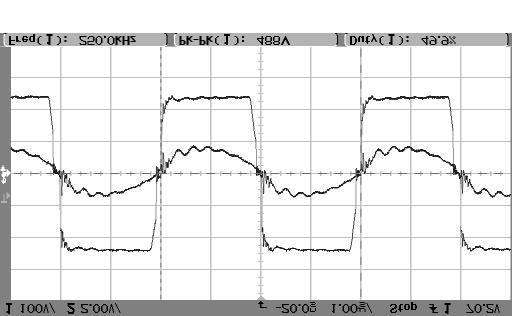
11 Fig.9 (f) Fig.9 (g) Fig.8 (a) shows the waveforms of load pulses, output voltage, output voltage of the BPS, output voltage of the FPS at nominal source voltage of 270 V. From this figure it can be seen that droop is less than 0.5 V/µ sec. and regulation is less than 0.01 %. Fig.8 (b) shows the step response of the total output voltage, output voltage of BPS, output voltage of FPS for a step change of source voltage from 243 V to 297 V. Transient variations of these voltages decay in a time less than 5.2 m-secs. Fig.8 (c) to (e) give the inverter output voltage and tank current waveforms of BPS and FPS under source voltages of 243 V, 270 V, and 297 V respectively. In all these conditions the BPS can be seen to be always in square wave mode of operation and continuous conduction. Hence all the devices of BPS are always under ZVS. Whereas FPS enters into mode-2 operation as the source voltage increases from 243 V to 297 V. This is because of reduction in the tank current as power handled by the FPS decreases as the source voltage increases. Under these conditions of high source voltage, ZVS has to be ensured for the devices of FPS by external means. It is done by an additional inductor and split capacitor combination across the DC bus. This arrangement is required only for the devices of one leg of the inverter whereas the devices of other leg are always under ZVS. Fig.9 (a) shows the load voltage waveform with an output voltage of 1 KV, load switching frequency of 125 KHz, and duty cycle of 10 %. In figs.9 (b) to (g) channel-1 is used for tank voltage and channel-2 is used for tank current. In the tank voltage waveforms, peak-to-peak voltage is measured. Hence half of this voltage gives the corresponding DC source voltage for the inverter. For the tank current waveforms, per division value indicated can be taken as the corresponding Amps. / division. Figs.9 (b), (c), and (d) are the tank voltage and tank current waveforms of the BPS taken together. Figs.9 (e), (f), and (g) are the tank voltage and tank current waveforms of the FPS taken together. Conclusions The proposed two level converter is studied under various conditions of line and load. Controlling the output voltage of FPS regulates the final output voltage. BPS handles majority of the total power but the FPS handles only % of the total power. Hence the overall efficiency is mainly dictated by the BPS, which is close to 92 %. The regulation is observed to be less than 0.01 % and droop is les than 0.5 V/µ sec. Under the step change of the source voltage from 243 V to 297 V, the output voltage settles back in a time less than 5.2 mill-secs. Under varying conditions of source voltage and load, the FPS compensates in such a way that total output voltage is 1KV. The BPS always operates in continuous conduction mode (i.e., mode-1) ensuring ZVS under all conditions of line and load, as its duty cycle is always maximum and fixed. For the FPS, as its duty cycle may change under various
12 operating conditions, the range of ZVS is extended by external means. Finally the BPS and FPS put together give an efficiency > 85 % and satisfy all the performance specifications. Experimental results are found to tally with the simulation results. References [1] Rostad, A.S., Mc Cown, C.T., and Lawrence, D.O. : Application of the venable Converter to a series of satellite TWT power processors, IEEE PESC,1976, pp [2] Israelsen, B.P., Martin, J.R., Reeve, C.R., and scown, V.S. : A 2.5 KV high-reliability TWT power supply: Design techniques for high efficiency and low ripple, IEEE PESC, 1977, pp [3] Johnson, S.D., Witulski, A.F., Erickson, R.W. : Comparison of resonant topologies in high voltage DC applications, IEEE Trans. on Aero. and Elect. Systems, vol.24,no.3, May 1988, pp [4] Cheron, Y., Foch, H., and Salesses, J. : Study of a resonant converter using power transistor in a 25 KW X ray tube power supply, IEEE PESC, 1985, pp [5] Garcia, V., Rico, M., Sebastian, J., Hernando, M.M., and Uceda, J. : An optimized DC to DC converter topology for high voltage pulse load applications, IEEE PESC, 1994, pp [6] Pitel, I.J. : Phase modulated resonant power conversion techniques for high frequency inverters, IEEE Trans. on Ind. Appl. Vol. 22, 1986, pp [7] Tsai, F.S., and Lee, F.C. : Constant frequency, phase controlled resonant power processors, Proc. IEEE, IAS Annual meeting, 1986, pp [8] Ngo, K.D.T. : Analysis of a series resonant converter pulse - width - modulated or current controlled for low switching loss, IEEE Trans. on Power Electronics, vol.3, No.1 Jan., 1988, pp
Input Voltage Modulated High Voltage DC Power Supply Topology for Pulsed Load Applications
 Input oltage Modulated High oltage DC Power Supply Topology for Pulsed Load Applications N.ishwanathan, Dr..Ramanarayanan Power Electronics Group, Dept. of Electrical Engineering, IISc., Bangalore -- 560
Comparison of High Voltage DC Power Supply Topologies for Pulsed Load Applications
 Comparison of High Voltage DC Topologies for ulsed Load Applications N.Vishwanathan, V.Ramanarayanan Electronics Group, Dept. of Electrical Engineering, IISc., Bangalore -- 560 01, India. e-mail: nvn@ee.iisc.ernet.in,
CHAPTER 2 A SERIES PARALLEL RESONANT CONVERTER WITH OPEN LOOP CONTROL
 14 CHAPTER 2 A SERIES PARALLEL RESONANT CONVERTER WITH OPEN LOOP CONTROL 2.1 INTRODUCTION Power electronics devices have many advantages over the traditional power devices in many aspects such as converting
RESONANT CIRCUIT MODEL AND DESIGN FOR A HIGH FREQUENCY HIGH VOLTAGE SWITCHED-MODE POWER SUPPLY
 RESONANT CIRCUIT MODEL AND DESIGN FOR A HIGH FREQUENCY HIGH VOLTAGE SWITCHED-MODE POWER SUPPLY Gleyson L. Piazza, Ricardo L. Alves 2, Carlos H. Illa Font 3 and Ivo Barbi 3 Federal Institute of Santa Catarina,
Resonant Power Conversion
 Resonant Power Conversion Prof. Bob Erickson Colorado Power Electronics Center Department of Electrical, Computer, and Energy Engineering University of Colorado, Boulder Outline. Introduction to resonant
CHAPTER 3 MODIFIED FULL BRIDGE ZERO VOLTAGE SWITCHING DC-DC CONVERTER
 53 CHAPTER 3 MODIFIED FULL BRIDGE ZERO VOLTAGE SWITCHING DC-DC CONVERTER 3.1 INTRODUCTION This chapter introduces the Full Bridge Zero Voltage Switching (FBZVSC) converter. Operation of the circuit is
Chapter 6. Small signal analysis and control design of LLC converter
 Chapter 6 Small signal analysis and control design of LLC converter 6.1 Introduction In previous chapters, the characteristic, design and advantages of LLC resonant converter were discussed. As demonstrated
FGJTCFWP"KPUVKVWVG"QH"VGEJPQNQI[" FGRCTVOGPV"QH"GNGEVTKECN"GPIKPGGTKPI" VGG"246"JKIJ"XQNVCIG"GPIKPGGTKPI
 FGJTFWP"KPUKWG"QH"GEJPQNQI[" FGRTOGP"QH"GNGETKEN"GPIKPGGTKPI" GG"46"JKIJ"XQNIG"GPIKPGGTKPI Resonant Transformers: The fig. (b) shows the equivalent circuit of a high voltage testing transformer (shown
A HIGHLY EFFICIENT ISOLATED DC-DC BOOST CONVERTER
 A HIGHLY EFFICIENT ISOLATED DC-DC BOOST CONVERTER 1 Aravind Murali, 2 Mr.Benny.K.K, 3 Mrs.Priya.S.P 1 PG Scholar, 2 Associate Professor, 3 Assistant Professor Abstract - This paper proposes a highly efficient
DC-DC Resonant converters with APWM control
 IOSR Journal of Electrical and Electronics Engineering (IOSR-JEEE) ISSN: 2278-1676 Volume 2, Issue 5 (Sep-Oct. 2012), PP 43-49 DC-DC Resonant converters with APWM control Preeta John 1 Electronics Department,
EMBEDDED CONTROLLED ZVS DC-DC CONVERTER FOR ELECTROLYZER APPLICATION
 International Journal on Intelligent Electronic Systems, Vol. 5, No.1, January 2011 6 Abstract EMBEDDED CONTROLLED ZVS DC-DC CONVERTER FOR ELECTROLYZER APPLICATION Samuel Rajesh Babu R. 1, Henry Joseph
Novel Soft-Switching DC DC Converter with Full ZVS-Range and Reduced Filter Requirement Part I: Regulated-Output Applications
 184 IEEE TRANSACTIONS ON POWER ELECTRONICS, VOL. 16, NO. 2, MARCH 2001 Novel Soft-Switching DC DC Converter with Full ZVS-Range and Reduced Filter Requirement Part I: Regulated-Output Applications Rajapandian
Chapter 4 SOFT SWITCHED PUSH-PULL CONVERTER WITH OUTPUT VOLTAGE DOUBLER
 61 Chapter 4 SOFT SWITCHED PUSH-PULL CONVERTER WITH OUTPUT VOLTAGE DOUBLER S.No. Name of the Sub-Title Page No. 4.1 Introduction 62 4.2 Single output primary ZVS push-pull Converter 62 4.3 Multi-Output
ZCS-PWM Converter for Reducing Switching Losses
 IOSR Journal of Electrical and Electronics Engineering (IOSR-JEEE) e-issn: 2278-1676,p-ISSN: 2320-3331, Volume 9, Issue 1 Ver. III (Jan. 2014), PP 29-35 ZCS-PWM Converter for Reducing Switching Losses
SIMULATION STUDIES OF HALF-BRIDGE ISOLATED DC/DC BOOST CONVERTER
 POZNAN UNIVE RSITY OF TE CHNOLOGY ACADE MIC JOURNALS No 80 Electrical Engineering 2014 Adam KRUPA* SIMULATION STUDIES OF HALF-BRIDGE ISOLATED DC/DC BOOST CONVERTER In order to utilize energy from low voltage
Improvements of LLC Resonant Converter
 Chapter 5 Improvements of LLC Resonant Converter From previous chapter, the characteristic and design of LLC resonant converter were discussed. In this chapter, two improvements for LLC resonant converter
Analysis and Design of Soft Switched DC-DC Converters for Battery Charging Application
 ISSN (Online) : 239-8753 ISSN (Print) : 2347-67 International Journal of Innovative Research in Science, Engineering and Technology Volume 3, Special Issue 3, March 24 24 International Conference on Innovations
Simplified loss analysis and comparison of full-bridge, full-range-zvs DC-DC converters
 Sādhanā Vol. 33, Part 5, October 2008, pp. 481 504. Printed in India Simplified loss analysis and comparison of full-bridge, full-range-zvs DC-DC converters SHUBHENDU BHARDWAJ 1, MANGESH BORAGE 2 and SUNIL
Chapter 6 ACTIVE CLAMP ZVS FLYBACK CONVERTER WITH OUTPUT VOLTAGE DOULER
 185 Chapter 6 ACTIVE CLAMP ZVS FLYBACK CONVERTER WITH OUTPUT VOLTAGE DOULER S. No. Name of the Sub-Title Page No. 6.1 Introduction 186 6.2 Single output Active Clamped ZVS Flyback Converter 186 6.3 Active
High Step-Up DC-DC Converter
 International Journal of Innovative Research in Advanced Engineering (IJIRAE) ISSN: 349-163 Volume 1 Issue 7 (August 14) High Step-Up DC-DC Converter Praful Vijay Nandankar. Department of Electrical Engineering.
High Frequency Soft Switching Of PWM Boost Converter Using Auxiliary Resonant Circuit
 RESEARCH ARTICLE OPEN ACCESS High Frequency Soft Switching Of PWM Boost Converter Using Auxiliary Resonant Circuit C. P. Sai Kiran*, M. Vishnu Vardhan** * M-Tech (PE&ED) Student, Department of EEE, SVCET,
Soft Switched Resonant Converters with Unsymmetrical Control
 IOSR Journal of Electrical and Electronics Engineering (IOSR-JEEE) e-issn: 2278-1676,p-ISSN: 2320-3331, Volume 10, Issue 1 Ver. I (Jan Feb. 2015), PP 66-71 www.iosrjournals.org Soft Switched Resonant Converters
Oscillators. An oscillator may be described as a source of alternating voltage. It is different than amplifier.
 Oscillators An oscillator may be described as a source of alternating voltage. It is different than amplifier. An amplifier delivers an output signal whose waveform corresponds to the input signal but
A Double ZVS-PWM Active-Clamping Forward Converter: Analysis, Design, and Experimentation
 IEEE TRANSACTIONS ON POWER ELECTRONICS, VOL. 16, NO. 6, NOVEMBER 2001 745 A Double ZVS-PWM Active-Clamping Forward Converter: Analysis, Design, and Experimentation René Torrico-Bascopé, Member, IEEE, and
Figure 1: Closed Loop System
 SIGNAL GENERATORS 3. Introduction Signal sources have a variety of applications including checking stage gain, frequency response, and alignment in receivers and in a wide range of other electronics equipment.
A SINGLE STAGE DC-DC CONVERTER FEASIBLE TO BATTERY CHARGING FROM PV PANELS WITH HIGH VOLTAGE STEP UP CAPABILITY
 A SINGLE STAGE DC-DC CONVERTER FEASIBLE TO BATTERY CHARGING FROM PV PANELS WITH HIGH VOLTAGE STEP UP CAPABILITY Paulo P. Praça; Gustavo A. L. Henn; Ranoyca N. A. L. S.; Demercil S. Oliveira; Luiz H. S.
DUAL BRIDGE LLC RESONANT CONVERTER WITH FREQUENCY ADAPTIVE PHASE-SHIFT MODULATION CONTROL FOR WIDE VOLTAGE GAIN RANGE
 DUAL BRIDGE LLC RESONANT CONVERTER WITH FREQUENCY ADAPTIVE PHASE-SHIFT MODULATION CONTROL FOR WIDE VOLTAGE GAIN RANGE S M SHOWYBUL ISLAM SHAKIB ELECTRICAL ENGINEERING UNIVERSITI OF MALAYA KUALA LUMPUR,
Narasimharaju. Balaraju *1, B.Venkateswarlu *2
 Narasimharaju.Balaraju*, et al, [IJRSAE]TM Volume 2, Issue 8, pp:, OCTOBER 2014. A New Design and Development of Step-Down Transformerless Single Stage Single Switch AC/DC Converter Narasimharaju. Balaraju
CHAPTER 3. SINGLE-STAGE PFC TOPOLOGY GENERALIZATION AND VARIATIONS
 CHAPTER 3. SINGLE-STAGE PFC TOPOLOG GENERALIATION AND VARIATIONS 3.1. INTRODUCTION The original DCM S 2 PFC topology offers a simple integration of the DCM boost rectifier and the PWM DC/DC converter.
A LLC RESONANT CONVERTER WITH ZERO CROSSING NOISE FILTER
 A LLC RESONANT CONVERTER WITH ZERO CROSSING NOISE FILTER M. Mohamed Razeeth # and K. Kasirajan * # PG Research Scholar, Power Electronics and Drives, Einstein College of Engineering, Tirunelveli, India
CHAPTER 2 AN ANALYSIS OF LC COUPLED SOFT SWITCHING TECHNIQUE FOR IBC OPERATED IN LOWER DUTY CYCLE
 40 CHAPTER 2 AN ANALYSIS OF LC COUPLED SOFT SWITCHING TECHNIQUE FOR IBC OPERATED IN LOWER DUTY CYCLE 2.1 INTRODUCTION Interleaving technique in the boost converter effectively reduces the ripple current
THE classical solution of ac dc rectification using a fullwave
 630 IEEE TRANSACTIONS ON INDUSTRIAL ELECTRONICS, VOL. 44, NO. 5, OCTOBER 1997 The Discontinuous Conduction Mode Sepic and Ćuk Power Factor Preregulators: Analysis and Design Domingos Sávio Lyrio Simonetti,
A Novel Single-Stage Push Pull Electronic Ballast With High Input Power Factor
 770 IEEE TRANSACTIONS ON INDUSTRIAL ELECTRONICS, VOL. 48, NO. 4, AUGUST 2001 A Novel Single-Stage Push Pull Electronic Ballast With High Input Power Factor Chang-Shiarn Lin, Member, IEEE, and Chern-Lin
A Three-Phase AC-AC Buck-Boost Converter using Impedance Network
 A Three-Phase AC-AC Buck-Boost Converter using Impedance Network Punit Kumar PG Student Electrical and Instrumentation Engineering Department Thapar University, Patiala Santosh Sonar Assistant Professor
Design, Analysis and Simulation of Closed loop Synchronous Buck Converter using k-factor method
 Volume 114 No. 10 2017, 457-465 ISSN: 1311-8080 (printed version); ISSN: 1314-3395 (on-line version) url: http://www.ijpam.eu ijpam.eu Design, Analysis and Simulation of Closed loop Synchronous Buck Converter
Soft switching of multioutput flyback converter with active clamp circuit
 Soft switching of multioutput flyback converter with active clamp circuit Aruna N S 1, Dr S G Srivani 2, Balaji P 3 PG Student, Dept. of EEE, R.V. College of Engineering, Bangalore, Karnataka, India 1
Chapter 6 Soft-Switching dc-dc Converters Outlines
 Chapter 6 Soft-Switching dc-dc Converters Outlines Classification of soft-switching resonant converters Advantages and disadvantages of ZCS and ZVS Zero-current switching topologies The resonant switch
Available online Journal of Scientific and Engineering Research, 2014, 1(2): Research Article
: Research Article") Available online www.jsaer.com, 2014, 1(2):44-54 Research Article ISSN: 2394-2630 CODEN(USA): JSERBR Control and Design of High Frequency Power Distribution System Almond D Souza St. Xavier's Catholic
Available online www.jsaer.com, 2014, 1(2):44-54 Research Article ISSN: 2394-2630 CODEN(USA): JSERBR Control and Design of High Frequency Power Distribution System Almond D Souza St. Xavier's Catholic
Simulation and Analysis of Zero Voltage Switching PWM Full Bridge Converter
 Simulation and Analysis of Zero Voltage Switching PWM Full Bridge Converter 1 Neha Gupta, 2 Dr. A.K. pandey, 3 Dr. K.G. Upadhyay 1. M.Tech(Power Electronics & Drives), Electrical Engineering Department,
SWITCHED CAPACITOR VOLTAGE CONVERTERS
 SWITCHED CAPACITOR VOLTAGE CONVERTERS INTRODUCTION In the previous section, we saw how inductors can be used to transfer energy and perform voltage conversions. This section examines switched capacitor
IMPLEMENTATION OF FM-ZCS-QUASI RESONANT CONVERTER FED DC SERVO DRIVE
 IMPLEMENTATION OF FM-ZCS-QUASI RESONANT CONVERTER FED DC SERVO DRIVE 1 K. NARASIMHA RAO, 2 DR V.C. VEERA REDDY 1 Research Scholar,Department of Electrictrical Engg,S V University, Tirupati, India 2 Professor,
Chapter 3 : Closed Loop Current Mode DC\DC Boost Converter
 Chapter 3 : Closed Loop Current Mode DC\DC Boost Converter 3.1 Introduction DC/DC Converter efficiently converts unregulated DC voltage to a regulated DC voltage with better efficiency and high power density.
Precise Analytical Solution for the Peak Gain of LLC Resonant Converters
 680 Journal of Power Electronics, Vol. 0, No. 6, November 200 JPE 0-6-4 Precise Analytical Solution for the Peak Gain of LLC Resonant Converters Sung-Soo Hong, Sang-Ho Cho, Chung-Wook Roh, and Sang-Kyoo
Comparative Analysis of Power Factor Correction Techniques for AC/DC Converter at Various Loads
 ISSN 2393-82 Vol., Issue 2, October 24 Comparative Analysis of Power Factor Correction Techniques for AC/DC Converter at Various Loads Nikita Kolte, N. B. Wagh 2 M.Tech.Research Scholar, PEPS, SDCOE, Wardha(M.S.),India
Comparative Analysis of Control Strategies for Modular Multilevel Converters
 IEEE PEDS 2011, Singapore, 5-8 December 2011 Comparative Analysis of Control Strategies for Modular Multilevel Converters A. Lachichi 1, Member, IEEE, L. Harnefors 2, Senior Member, IEEE 1 ABB Corporate
Linear Transformer based Sepic Converter with Ripple Free Output for Wide Input Range Applications
 Linear Transformer based Sepic Converter with Ripple Free Output for Wide Input Range Applications Karthik Sitapati Professor, EEE department Dayananda Sagar college of Engineering Bangalore, India Kirthi.C.S
Reduce Load Capacitance in Noise-Sensitive, High-Transient Applications, through Implementation of Active Filtering
 WHITE PAPER Reduce Load Capacitance in Noise-Sensitive, High-Transient Applications, through Implementation of Active Filtering Written by: Chester Firek, Product Marketing Manager and Bob Kent, Applications
Linear Peak Current Mode Controlled Non-inverting Buck-Boost Power-Factor-Correction Converter
 Linear Peak Current Mode Controlled Non-inverting Buck-Boost Power-Factor-Correction Converter Mr.S.Naganjaneyulu M-Tech Student Scholar Department of Electrical & Electronics Engineering, VRS&YRN College
A Series-Resonant Half-Bridge Inverter for Induction-Iron Appliances
 IEEE PEDS 2011, Singapore, 5-8 December 2011 A Series-Resonant Half-Bridge Inverter for Induction-Iron Appliances N. Sanajit* and A. Jangwanitlert ** * Department of Electrical Power Engineering, Faculty
A HIGH EFFICIENT IMPROVED SOFT SWITCHED INTERLEAVED BOOST CONVERTER
 A HIGH EFFICIENT IMPROVED SOFT SWITCHED INTERLEAVED BOOST CONVERTER A.Karthikeyan, 1 S.Athira, 2 PSNACET, Dindigul, India. janakarthi@rediffmail.com, athiraspecial@gmail.com ABSTRACT In this paper an improved
IN THE high power isolated dc/dc applications, full bridge
 354 IEEE TRANSACTIONS ON POWER ELECTRONICS, VOL. 21, NO. 2, MARCH 2006 A Novel Zero-Current-Transition Full Bridge DC/DC Converter Junming Zhang, Xiaogao Xie, Xinke Wu, Guoliang Wu, and Zhaoming Qian,
Design considerations for a Half- Bridge LLC resonant converter
 Design considerations for a Half- Bridge LLC resonant converter Why an HB LLC converter Agenda Configurations of the HB LLC converter and a resonant tank Operating states of the HB LLC HB LLC converter
BLDC Motor Speed Control and PFC Using Isolated Zeta Converter
 BLDC Motor Speed Control and PFC Using Isolated Zeta Converter Vimal M 1, Sunil Kumar P R 2 PG Student, Dept. of EEE. Government Engineering College Idukki, India 1 Asst. Professor, Dept. of EEE Government
Zero voltage switching active clamp buck-boost stage Cuk converter
 Zero voltage switching active clamp buck-boost stage Cuk converter B.R. Lin and C.L. Huang Abstract: The paper presents an active clamp buck-boost stage Cuk converter to achieve soft switching commutation.
INVESTIGATION OF GATE DRIVERS FOR SNUBBERLESS OVERVOLTAGE SUPPRESSION OF POWER IGBTS
 INVESTIGATION OF GATE DRIVERS FOR SNUBBERLESS OVERVOLTAGE SUPPRESSION OF POWER IGBTS Alvis Sokolovs, Iļja Galkins Riga Technical University, Department of Power and Electrical Engineering Kronvalda blvd.
DESIGN AND IMPLEMENTATION OF RESONANT CIRCUIT BASED ON HALF-BRIDGE BOOST RECTIFIER WITH OUTPUT VOLTAGE BALANCE CONTROL
 DESIGN AND IMPLEMENTATION OF RESONANT CIRCUIT BASED ON HALF-BRIDGE BOOST RECTIFIER WITH OUTPUT VOLTAGE BALANCE CONTROL B.Mehala 1, Anithasampathkuar 2 PG Student 1, Assistant Professor 2 Bharat University
Simulation of a novel ZVT technique based boost PFC converter with EMI filter
 ISSN 1746-7233, England, UK World Journal of Modelling and Simulation Vol. 4 (2008) No. 1, pp. 49-56 Simulation of a novel ZVT technique based boost PFC converter with EMI filter P. Ram Mohan 1 1,, M.
THREE-PHASE REDUCED TWO SWITCH HIGH POWER FACTOR BUCK-TYPE RECTIFIER
 THREE-PHASE REDUCED TWO SWITCH HIGH POWER FACTOR BUCK-TYPE RECTIFIER D.Karthikraj 1, A.Sivakumar 2, C.Mahendraraj 3 and Dr.M.Sasikumar 4 1,2,3 PG Scholar, Jeppiaar Engineering College, Chennai, Tamilnadu,
Impact of Fringing Effects on the Design of DC-DC Converters
 Impact of Fringing Effects on the Design of DC-DC Converters Michael Seeman, Ph.D. Founder / CEO. 2018 APEC PSMA/PELS 2018. Outline Fringe-field loss: What does a power supply designer need to know? Which
A THREE-PHASE HIGH POWER FACTOR TWO-SWITCH BUCK- TYPE CONVERTER
 A THREE-PHASE HIGH POWER FACTOR TWO-SWITCH BUCK- TYPE CONVERTER SEEMA.V. 1 & PRADEEP RAO. J 2 1,2 Electrical and Electronics, The Oxford College of Engineering, Bangalore-68, India Email:Seema.aish1@gmail.com
Fuzzy Logic Controller Based Three-phase Shunt Active Filter for Line Harmonics Reduction
 Journal of Computer Science 3 (: 76-8, 7 ISSN 549-3636 7 Science Publications Fuzzy Logic Controller Based Three-phase Shunt Active Filter for Line Harmonics Reduction C.Sharmeela, M.R.Mohan, G.Uma, J.Baskaran
A Single Switch High Gain Coupled Inductor Boost Converter
 International Research Journal of Engineering and Technology (IRJET) e-issn: 2395-0056 Volume: 04 Issue: 02 Feb -2017 www.irjet.net p-issn: 2395-0072 A Single Switch High Gain Coupled Inductor Boost Converter
Testing and Stabilizing Feedback Loops in Today s Power Supplies
 Keywords Venable, frequency response analyzer, impedance, injection transformer, oscillator, feedback loop, Bode Plot, power supply design, open loop transfer function, voltage loop gain, error amplifier,
Design of High-efficiency Soft-switching Converters for High-power Microwave Generation
 Journal of the Korean Physical Society, Vol. 59, No. 6, December 2011, pp. 3688 3693 Design of High-efficiency Soft-switching Converters for High-power Microwave Generation Sung-Roc Jang and Suk-Ho Ahn
A Component-Reduced Zero-Voltage Switching Three-Level DC-DC Converter Qin, Zian; Pang, Ying; Wang, Huai; Blaabjerg, Frede
 alborg Universitet Component-Reduced Zero-Voltage Switching Three-Level DC-DC Converter Qin, Zian; Pang, Ying; Wang, Huai; laabjerg, Frede Published in: Proceedings of IECON 16 - nd nnual Conference of
SSRG International Journal of Electrical and Electronics Engineering (SSRG-IJEEE) volume 1 Issue 10 Dec 2014
 volume 1 Issue 10 Dec 2014") Soft switching power factor correction of Single Phase and Three Phases boost converter V. Praveen M.Tech, 1 V. Masthanaiah 2 1 (Asst.Professor, Visvodaya engineering college, Kavali, SPSR Nellore Dt.
Soft switching power factor correction of Single Phase and Three Phases boost converter V. Praveen M.Tech, 1 V. Masthanaiah 2 1 (Asst.Professor, Visvodaya engineering college, Kavali, SPSR Nellore Dt.
ANALYSIS OF SINGLE-PHASE Z-SOURCE INVERTER 1
 ANALYSIS OF SINGLE-PHASE Z-SOURCE INVERTER 1 K. N. Madakwar, 2 Dr. M. R. Ramteke VNIT-Nagpur Email: 1 kapil.madakwar@gmail.com, 2 mrr_vrce@rediffmail.com Abstract: This paper deals with the analysis of
A New ZVS Bidirectional DC-DC Converter With Phase-Shift Plus PWM Control Scheme
 A New ZVS Bidirectional DC-DC Converter With Phase-Shift Plus PWM Control Scheme Huafeng Xiao, Liang Guo, Shaojun Xie College of Automation Engineering,Nanjing University of Aeronautics and Astronautics
Figure.1. Block of PV power conversion system JCHPS Special Issue 8: June Page 89
 Soft Switching Converter with High Voltage Gain for Solar Energy Applications S. Hema*, A. Arulmathy,V. Saranya, S. Yugapriya Department of EEE, Veltech, Chennai *Corresponding author: E-Mail: hema@veltechengg.com
ADVANCED HYBRID TRANSFORMER HIGH BOOST DC DC CONVERTER FOR PHOTOVOLTAIC MODULE APPLICATIONS
 ADVANCED HYBRID TRANSFORMER HIGH BOOST DC DC CONVERTER FOR PHOTOVOLTAIC MODULE APPLICATIONS SHAIK ALLIMBHASHA M.Tech(PS) NALANDA INSTITUTE OF ENGINEERING AND TECHNOLOGY G V V NAGA RAJU Assistant professor
A Single Phase Single Stage AC/DC Converter with High Input Power Factor and Tight Output Voltage Regulation
 638 Progress In Electromagnetics Research Symposium 2006, Cambridge, USA, March 26-29 A Single Phase Single Stage AC/DC Converter with High Input Power Factor and Tight Output Voltage Regulation A. K.
Improving Passive Filter Compensation Performance With Active Techniques
 IEEE TRANSACTIONS ON INDUSTRIAL ELECTRONICS, VOL. 50, NO. 1, FEBRUARY 2003 161 Improving Passive Filter Compensation Performance With Active Techniques Darwin Rivas, Luis Morán, Senior Member, IEEE, Juan
CHAPTER 2 DESIGN AND MODELING OF POSITIVE BUCK BOOST CONVERTER WITH CASCADED BUCK BOOST CONVERTER
 17 CHAPTER 2 DESIGN AND MODELING OF POSITIVE BUCK BOOST CONVERTER WITH CASCADED BUCK BOOST CONVERTER 2.1 GENERAL Designing an efficient DC to DC buck-boost converter is very much important for many real-time
SHUNT ACTIVE POWER FILTER
 75 CHAPTER 4 SHUNT ACTIVE POWER FILTER Abstract A synchronous logic based Phase angle control method pulse width modulation (PWM) algorithm is proposed for three phase Shunt Active Power Filter (SAPF)
Design of an 80kV, 40A Resonant SMPS for Pulsed Power Applications
 Design of an 8kV, 4A Resonant SMPS for Pulsed Power Applications Paul Nonn, Andrew Seltzman, Jay Anderson University of Wisconsin Madison Department of Physics IEEE IPMHVC June 4, 212 Three Phase Resonant
Chapter 3 HARD SWITCHED PUSH-PULL TOPOLOGY
 35 Chapter 3 HARD SWITCHED PUSH-PULL TOPOLOGY S.No. Name of the Sub-Title Page No. 3.1 Introduction 36 3.2 Single Output Push Pull Converter 36 3.3 Multi-Output Push-Pull Converter 37 3.4 Closed Loop Simulation
Chapter 2 MODELING AND CONTROL OF PEBB BASED SYSTEMS
 Chapter 2 MODELING AND CONTROL OF PEBB BASED SYSTEMS 2.1 Introduction The PEBBs are fundamental building cells, integrating state-of-the-art techniques for large scale power electronics systems. Conventional
I. INTRODUCTION. 10
 Closed-loop speed control of bridgeless PFC buck- boost Converter-Fed BLDC motor drive Sanjay S Siddaganga Institute Of Technology/Electrical & Electronics, Tumkur, India Email: sanjayshekhar04@gmail.com
LECTURE 3 How is Power Electronics Accomplished:
 1 LECTURE 3 How is Power Electronics Accomplished: I. General Power Electronics System A. Overview B. Open Loop No Feedback Case C. Feedback Case and Major Issues D. Duty Cycle VARATION as a Control Means
A NEW SOFT-SWITCHING ACTIVE CLAMP SCHEME FOR FULL-BRIDGE ISOLATED CURRENT FED DC-DC CONVERTER FED DRIVES
 Indian Streams Research Journal Vol.2,Issue.IV/May; 12pp.1-4 M.Geetha ISSN:-2230-7850 Research Papers A NEW SOFT-SWITCHING ACTIVE CLAMP SCHEME FOR FULL-BRIDGE ISOLATED CURRENT FED DC-DC CONVERTER FED DRIVES
High Efficiency Isolated DC/DC Converter using Series Voltage Compensation. Abstract. 1. Introduction. 2. Proposed Converter
 High Efficiency Isolated DC/DC Converter using Series Voltage Compensation Jun-ichi Itoh, Satoshi Miyawaki, Nagaoka University of Technology, Japan Kazuki Iwaya, TDK-Lambda Corporation, Japan Abstract
A Novel Concept in Integrating PFC and DC/DC Converters *
 A Novel Concept in Integrating PFC and DC/DC Converters * Pit-Leong Wong and Fred C. Lee Center for Power Electronics Systems The Bradley Department of Electrical and Computer Engineering Virginia Polytechnic
A Thyristor Controlled Three Winding Transformer as a Static Var Compensator
 Abstract: A Thyristor Controlled Three Winding Transformer as a Static Var Compensator Vijay Bendre, Prof. Pat Bodger, Dr. Alan Wood. Department of Electrical and Computer Engineering, The University of
PERFORMANCE OF INDUCTION HEATING TOPOLOGIES WITH VARIOUS SWITCHING SCHEMES
 PERFORMANCE OF INDUCTION HEATING TOPOLOGIES WITH VARIOUS SWITCHING SCHEMES Janet Teresa K. Cyriac 1, Sreekala P. 2 P.G. Scholar 1, Assistant Professor 2 Amal Jyothi College of Engineering Kanjirapally,
HIGH FREQUENCY CLASS DE CONVERTER USING A MULTILAYER CORELESS PCB TRANSFORMER
 HIGH FREQUENCY CLASS DE CONVERTER USING A MULTILAYER CORELESS PCB TRANSFORMER By Somayeh Abnavi A thesis submitted to the Department of Electrical and Computer Engineering In conformity with the requirements
Improvement of Power Quality in Distribution System using D-STATCOM With PI and PID Controller
 Improvement of Power Quality in Distribution System using D-STATCOM With PI and PID Controller Phanikumar.Ch, M.Tech Dept of Electrical and Electronics Engineering Bapatla Engineering College, Bapatla,
DIGITAL SIMULATION OF MULTILEVEL INVERTER BASED STATCOM
 DIGITAL SIMULATION OF MULTILEVEL INVERTER BASED STATCOM G.SUNDAR, S.RAMAREDDY Research Scholar, Bharath University Chenna Professor Jerusalam College of Engg. Chennai ABSTRACT This paper deals with simulation
Modified Resonant Transition Switching for Buck Converter
 Modified Resonant Transition Switching for Buck Converter Derick Mathew*, Mohanraj M*, Midhun Raju** *Power Electronics and Drives, Karunya University, Coimbatore, India **Renewable Energy Technologies,
Keywords: Forward Boost Converter, SMPS, Power Factor Correction, Power Quality, Efficiency.
 www.semargroups.org, www.ijsetr.com ISSN 2319-8885 Vol.02,Issue.19, December-2013, Pages:2243-2247 Power Quality Improvement in Multi-Output Forward Boost Converter NARLA KOTESWARI 1, V. MADHUSUDHAN REDDY
Single Phase Induction Motor Drive using Modified SEPIC Converter and Three Phase Inverter
 Single Phase Induction Motor Drive using Modified SEPIC Converter and Three Phase Inverter Ajeesh P R PG Student, M. Tech Power Electronics, Mar Athanasius College of Engineering, Kerala, India, Dr. Babu
Three-phase soft-switching inverter with coupled inductors, experimental results
 BULLETIN OF THE POLISH ACADEMY OF SCIENCES TECHNICAL SCIENCES, Vol. 59, No. 4, 2011 DOI: 10.2478/v10175-011-0065-3 POWER ELECTRONICS Three-phase soft-switching inverter with coupled inductors, experimental
Improved Power Quality Bridgeless Isolated Cuk Converter Fed BLDC Motor Drive
 Improved Power Quality Bridgeless Isolated Cuk Converter Fed BLDC Motor Drive 1 Midhun Mathew John, 2 Phejil K Paul 1 PG Scholar, 2 Assistant Professor, 1 Electrical and Electronics Engineering 1 Mangalam
CHAPTER 5 The Parallel Resonant Converter
 CHAPTER 5 The Parallel Resonant Converter T he objective of this chapter is to describe the operation of the parallel resonant converter in detail. The concepts developed in chapter 3 are used to derive
Single Phase Single Stage Power Factor Correction Converter with Phase Shift PWM Technique
 Single Phase Single Stage Power Factor Correction Converter with Phase Shift PWM Technique G.KAVIARASAN 1, M.G ANAND 2 1 PG Scholar, Department of Power Electronics and Drives THE KAVERY ENGINEERNG COLLEGE,salem
Voltage Fed DC-DC Converters with Voltage Doubler
 Chapter 3 Voltage Fed DC-DC Converters with Voltage Doubler 3.1 INTRODUCTION The primary objective of the research pursuit is to propose and implement a suitable topology for fuel cell application. The
Integration of Two Flyback Converters at Input PFC Stage for Lighting Applications
 Integration of Two Flyback Converters at Input PFC Stage for Lighting Applications Anjali.R.N 1, K. Shanmukha Sundar 2 PG student [Power Electronics], Dept. of EEE, Dayananda Sagar College of Engineering,
K.Vijaya Bhaskar. Dept of EEE, SVPCET. AP , India. S.P.Narasimha Prasad. Dept of EEE, SVPCET. AP , India.
 A Closed Loop for Soft Switched PWM ZVS Full Bridge DC - DC Converter S.P.Narasimha Prasad. Dept of EEE, SVPCET. AP-517583, India. Abstract: - This paper propose soft switched PWM ZVS full bridge DC to
Analysis, design and implementation of an improved two-switch zero-current zero-voltage pulse-width modulation forward converter
 Published in IET Power Electronics Received on 11th June 2013 Revised on 21st July 2013 Accepted on 17th August 2013 ISSN 1755-4535 Analysis, design and implementation of an improved two-switch zero-current
HI-BRIDGE RESONANT SOFT-SWITCHED BOOST CONVERTER
 HI-BRIDGE RESONANT SOFT-SWITCHED BOOST CONVERTER 1 ELANGOVAN.S, 2 MARIMUTHU. M, 3 VIJYALASKMI 1,2,3 Department of Electrical and Electronics Engineering, Saranathan College of Engineering, Triuchirapalli,
CHAPTER 3 DC-DC CONVERTER TOPOLOGIES
 47 CHAPTER 3 DC-DC CONVERTER TOPOLOGIES 3.1 INTRODUCTION In recent decades, much research efforts are directed towards finding an isolated DC-DC converter with high volumetric power density, low electro