SELECTION GUIDE. Interfaces galvanic insulation.
|
|
|
- Phyllis Richardson
- 6 years ago
- Views:
Transcription


1 SELECTION GUIDE Interfaces galvanic insulation
2
3 1. and notions of intrinsic safety Notions of intrinsic safety Mechanical properties Certifications Dimensions Selection guide 1. Analog inputs - standard Analog inputs - HART compatible Analog inputs - converter Analog inputs - isolator Digital inputs - relay outputs Digital inputs - transistor outputs Digital inputs - output relays with input memory Digital inputs - signal isolator Analog inputs - converter Analog output - isolator Impedance transfer table (BXNI*T and BXNI*A) Digital outputs - 1 channel power supplies Digital outputs - 2-channel power supplies controlled by 24 V DC Digital outputs - 2-channel power supplies controlled by contact Power curves and IS parameters (BXNE) Example of BXNE selection Digital inputs - opto-isolator output signal isolator Digital outputs - relay output signal isolator Temperature inputs - converter Potentiometer inputs - resistance - converter Universal inputs - threshold relays Use of galvanic insulation 1. Connection Installation Fixing and mounting Location Electrical connection Mechanical properties Cable routing Adjustments and configuration Maintenance Dismounting Assembly methods 62 GEORGIN France : Tel : +33 (0) Fax : +33 (0) regulateurs@georgin.com GEORGIN Belgium : Tel : Fax : info@georgin.be
4

5 1. and notions of intrinsic safety 3

6 1. A galvanic insulation barrier is an associated equipment that is generally installed in the safe area. Its main function in safety terms is to limit the level of energy that may appear in an electric circuit routed through a hazardous area, whatever the connection established upstream of this barrier. A galvanic insulation barrier comprises: safety transformers opto-isolators intrinsic safety relays resistances fuses Zener diodes Like any other intrinsic safety equipment, this device enables short circuits between cables or with grounded metal parts without danger. The interface through a galvanic insulation barrier is different from other interface modes: Cables routed through hazardous areas have no common points with those in safe areas. There is therefore no use in grounding such a barrier. Figure 1 presents a galvanic insulation barrier (B) that feeds any type of equipment. This barrier is controlled by the programmable logic controller (PLC) (C). Details of the components of an intrinsic safety barrier: 4
 and the controller (C).")

.")
 Controlling the voltage on the relay coil opens and closes the contact.")
7 Details of the components of an intrinsic safety barrier: Galvanic insulation In figure 1 the galvanic insulation of the barrier (F) is represented in blue. There are no electrical connections between the equipment circuit (A) and the controller (C). Safety transformers (D) It is "foolproof" and used to maintain full insulation between the primary and secondary circuits. Useful for powering the intrinsic safety circuit. For a mains power supply, the electrical insulation is 2500 V AC. Energy limitation The components used to limit energy - Zener diode, resistance and fuse - are located on the safety transformer output (D). The value of these components define the intrinsic safety parameters of the barrier (see chapter 2. IS parameters). Current path under normal operations Current path with overvoltage The Zener diode becomes conductive The fuse protects the Zener diodes against destruction Intrinsic safety relay (E) Controlling the voltage on the relay coil opens and closes the contact. Just like the intrinsic safety transformer, this component conserves the integrity of the galvanic insulation. 5

8 Opto-isolator This component is not represented on figure 1. It is used to transfer information from the intrinsic safety circuit to the conventional part of the circuit while conserving the integrity of the galvanic insulation. The opening of the output transistor (EF) is controlled via a photo-sensitive receiver. When the current passes via (JH), a LED lights up and makes the transistor conductive. In addition to their insulation and energy limitation function, active galvanic insulation barriers are useful and employed in different applications: Signal conversion Analog or digital output repeaters Threshold relays Alarm functions etc. These functions are described in greater detail in the Selection Guide chapter, page 13. 6
9 2. Notions of intrinsic safety Like any intrinsic safety device connected to a sensor (also an IS device), the whole constitutes what the standard refers to as an "intrinsic safety system", the parameters of which must be compatible in terms of intrinsic safety. European Directive 1999/92/EC (the ATEX Directive) requires that the compliance of the safety system must be proven. The definition of a galvanic insulation barrier therefore requires the collection of a certain amount of information concerning its environment, to ensure that the system operates correctly and is reliable. So to define a suitable barrier, the following information is required: Full references of the associated equipment and other equipment in the hazardous area: To identify the device in question in the ATEX certificate and the technical data sheet. Technical data sheet or instruction notice for the interfaces and equipment in the hazardous area: To identify the metrological data of the equipment. ATEX Certificate for the interfaces and equipment in the hazardous area: To identify the intrinsic safety parameters and the device markings. An intrinsic safety system generally comprises: Intrinsic safety equipment installed in a hazardous area Associated equipment installed in the safe area Connection cables Accessories (junction boxes, power outlets, switches, etc.) Associated equipment: It is located in the safe area. In terms of intrinsic safety, it must be considered as an energy source. This energy source is characterized by three parameters: Voltage: U o Current: I o Power: P o This signifies that the associated equipment may never supply a voltage greater than U o, a current greater than I o or power greater than P o to an external medium. Cabling: For each piece of associated equipment, the limit properties of the external cabling C o and L o are defined to ensure that the system remains safe: C o represents the maximum capacitance that can be connected to the associated equipment L o represents the maximum inductance that can be connected to the associated equipment C i represents the sum of the capacities of the cable and the intrinsic safety equipment on the loop. L i represents the sum of the inductances of the cable and the intrinsic safety equipment on the loop. 7
10 Intrinsic safety equipment: Located in the hazardous area, it must be considered as a receiver of energy due to the terminals that are connected to the associated equipment. This energy receiver is characterized by three parameters that define the maximum limits: U i, I i, P i. This means that as long as the characteristics of the energy supplied to it remain below U i, I i and P i, this intrinsic safety equipment will remain safe. Each piece of intrinsic safety equipment is also characterized by the values C i and L i which are the values of the capacity and internal inductance of the intrinsic safety equipment. The intrinsic safety parameters in a simple system (Receiver, barrier, equipment in hazardous area) are validated by comparing the intrinsic safety parameters of the barrier and the equipment in the area using the following rule: Verification of voltage: U o (barrier) U i (equipment in hazardous area) Verification of current: I o (barrier) I i (equipment in hazardous area) Verification of power: P o (barrier) P i (equipment in hazardous area) Verification of capacitance: C c (cable) + C i (equipment in hazardous area) C o (barrier) Verification of inductance: L c + L i (equipment in hazardous area) L o (barrier) 8
11 Let us consider an example: System composition: In hazardous area: A: Smart pressure transmitter Type Reference Manufacturer Marking Installation zones CE type certification ATEX declaration of confirmity Commercial data sheet Instruction manual FK* - ProcessX family FKPT03V52KABY0Y Georgin II 1 G Ex ia IIC T4 or T5 0, 1 or 2 (Gas) KEMA 10ATEX0031X dc-ceatex-processx-fren Ind A fc-fk*-fr fi-processx-fren In safe area: B: GEORGIN galvanic insulation barrier Type BXNT Reference BXNT6*** Manufacturer Georgin Marking II (1) G/D [Ex ia] IIC Installation areas Safe area CE type certification LCIE 02 ATEX 6104X ATEX declaration of confirmity dcceatex-pc-fren Commercial data sheet fc-bxlmnt-fren Instruction notice fu-bxlmn-fren C: Connection cable Type Shielded pair Reference HIJ Manufacturer DURAND Linear resistance 10 Ohms/Km Linear capacity 0.02 µf/km Linear inductance 1000 µh/km Length 700 meters 9
 U i (equipment in hazardous area) 27.")
12 The (U, I, P) safety parameters for A and B equipment are compatible for classification: II 1G/D Ex ia IIC T4 to T5 (depending on ambient temperature) For zones: 0, 1 and 2 / 20, 21 and 22 as per IEC L. A/ Analysis in terms of U, I and P Verification of voltage: U o (barrier) U i (equipment in hazardous area) 27.5 V 28 V Verification of current: I o (barrier) I i (equipment in hazardous area) 80.1 ma 94.3 ma Verification of power: P o (barrier) P i (equipment in hazardous area) mw 660 mw Equipment A limited by the voltages, current and power of equipment B. B/ Analysis in terms of C and L Verification of capacitance: C c (cable) + C i (equipment in hazardous area) C o (barrier) (0.02 µf x 0.7 km) µf µf 0.04 µf µf Verification of inductance: L c + L i (equipment in hazardous area) L o (barrier) (1000 µh x 0.7 km) µh µh 1300 µh µh The device in the area has capacitance and inductance values that are compatible with the maximum external values of the associated equipment. 10
13 2. 11
14 1. Mechanical properties Installation In safe area Dimensions ABS case Weight 200 g Storage temperature -25 to 70 C Operating temperature -10 to 60 C Relative humidity 5 to 95% without condensation Connection Plug-in cage clamp terminals Mounting On rail EN Certifications EMC EN & IEC Low Voltage Directive IEC Category II (overvoltage) Intrinsic Safety EN & EN [Ex ia] I or [Ex ia] IIC or [Ex ia] IIB [Ex iad] I or [Ex iad] IIC or [Ex iad] IIB LCIE N 02 ATEX 6104 and LCIE03 ATEX 6469X (for BPX) IEC / IEC / IEC / IEC / IEC ATEX Classification CE 0081 II (1) G/D NF C SIL Classification SIL 2 according to IEC (only concerns certain types of equipment, see SIL certificate). 3. Dimensions (mm) RDN1****** RDN2****** All other equipment 12

15 3. Selection guide 13
16 Ref. BXNT6 1. Analog inputs - standard Description (see technical data sheet for further information) The device represented is an intrinsically safe, galvanic-insulated power supply for transmitters. For the 2-wire transmitter (connection between H+ and J- terminals) the device powers the 4/20 ma sensor (16.5 V at 20 ma). If the BXNT6 is connected to a current generator (J+ and L-), it does not supply power to the loop. The 4/20 ma output can be connected as active or passive, depending on whether the controller powers the loop or not. (Terminals E+ and F-: The BXNT6 supplies voltage to the controller input). The input signal (HJ) is read and transmitted to the safe zone through precise analog processing. This device is a triple galvanic insulation (Input / Output / Module power supply). Type Option Power supply BXNT6 00 No option E 110/230 V AC B0 Screw terminals 2 24/48 V DC IS parameters ATEX marking HJ terminals: Uo: 27.5 V Io: 80.1 ma Po: ma Co, IIC: 86 nf Lo, IIC: 2.8 mh Presence of voltage indicated by a green LED Adjustment potentiometers for the source and the curve of the 4/20 ma output BXMT When space savings are necessary, it is possible to use the two-channel version. The two channels are independent and each have separate insulation. Type Option Power supply BXMT1 00 No option E 110/230 V AC B0 Screw terminals 2 24/48 V DC Presence of voltage indicated by a green LED. (1 LED per output channel) Adjustment potentiometers for the source and the curve of the 4/20 ma output. (1 set of potentiometers per channel) HJ terminals: Uo: 27.5 V Io: 80.1 ma Po: ma Co, IIC: 86 nf Lo, IIC: 2.8 mh To duplicate the 4/20 ma output, it is possible to use this 1-input / 2-output version. For this version, the two outputs are isolated from each other and from the input. Type Option Power supply BXLT1 00 No option E 110/230 V AC B0 Screw terminals 2 24/48 V DC HJ terminals: Uo: 27.5 V Io: 80.1 ma Po: ma Co, IIC: 86 nf Lo, IIC: 2.8 mh BXLT Presence of voltage indicated by a green LED. (1 LED per output channel) Adjustment potentiometers for the source and the curve of the 4/20 ma output. (1 set of potentiometers per channel) 14

17 Explanatory diagram I/O 1 Input / 2 Output 2 Inputs / 2 Outputs 1 Input / 1 Output 15
18 Ref. BXNTI6 2. Analog inputs - HART compatible Description (see technical data sheet for further information) The most common application using analog inputs is the interface with a 4/20 ma transmitter: The device represented is an intrinsically safe, galvanic-insulated power supply for transmitters. For the 2-wire transmitter (connection between H+ and J- terminals) the device powers the 4/20mA sensor (16.5 V at 20 ma). The 4/20 ma output on the BXNT16 (F+E-) may only be active (the module supplies power to the loop) as the 4/20 ma must be modulated to retranscribe the HART protocol frames read on input. The input signal (HJ) is read and transmitted to the safe zone through precise analog processing. This device is a triple galvanic insulation (Input / Output / Module power supply). Type Option Power supply BXNTI6 00 No option E 110/230 V AC B0 Screw terminals 2 24/48 V DC IS parameters ATEX marking HJ terminals: Uo: 27.5 V Io: 80.1 ma Po: ma Co, IIC: 86 nf Lo, IIC: 2.8 mh BXMTI Presence of voltage indicated by a green LED Adjustment potentiometers for the source and the curve of the 4/20 ma output. When space savings are necessary, it is possible to use the two-channel version. The two channels are independent and each have separate insulation. Type Option Power supply BXMTI2 00 No option E 110/230 V AC B0 Screw terminals 2 24/48 V DC Presence of voltage indicated by a green LED. (1 LED per output channel) Adjustment potentiometers for the source and the curve of the 4/20 ma output. (1 set of potentiometers per channel) HJ terminals: Uo: 27.5 V Io: 80.1 ma Po: ma Co, IIC: 86 nf Lo, IIC: 2.8 mh To duplicate the 4/20 ma output, it is possible to use this 1-input / 2-output version. For this version, the two outputs are insulated from each other and from the input. Type Option Power supply BXLT12 00 No option E 110/230 V AC B0 Screw terminals 2 24/48 V DC HJ terminals: Uo: 27.5 V Io: 80.1 ma Po: ma Co, IIC: 86 nf Lo, IIC: 2.8 mh BXLTI Presence of voltage indicated by a green LED. (1 LED per output channel) Adjustment potentiometers for the source and the curve of the 4/20 ma output. (1 set of potentiometers per channel) 16


19 Explanatory diagram I/O 1 Input / 2 Output 2 Inputs / 2 Outputs 1 Input / 1 Output 17
20 Ref. BXNT1*** (ex) BXNT1***-00-A0 (example) BXNT1*** (example) 3. Analog inputs - converter Description (see technical data sheet for further information) The BXNT1 performs the same function as the BXNT6 (see Standard Analog Inputs) with the exception that this version (depending on the model) is capable of converting the input signal (e.g. Voltage 0-5 V) into another type of signal, voltage or current. In this example it performs a simple 4/20 or 0-20 ma / 4/20 ma insulation. This device features a different encoding depending on whether it is used on active or passive outputs: Type Option Power supply Input Output BXNT1 00 No option V AC 00 4/20 ma 00 4/20 ma B0 Screw terminals V AC 04 0/20 ma 03 0/20 ma 3 24 V DC 11 0/5 V 08 0/5 V 4 48 V DC 13 0/10V 09 0/10V XX Other on request A0 Passive 4/20 ma Presence of voltage indicated by a green LED Adjustment potentiometers for the source and the curve of the 4/20 ma output. In this example, the device represented is on a passive output (F+E-). Type Option Power supply Input Output XX Other on request BXNT1 00 No option V AC 00 4/20 ma 00 4/20 ma B0 Screw terminals V AC 04 0/20 ma 03 0/20 ma 3 24 V DC 11 0/5 V 08 0/5 V 4 48 V DC 13 0/10V A0 Passive 4/20 ma XX Other on request XX Other on request Presence of voltage indicated by a green LED Adjustment potentiometers for the source and the curve of the 4/20 ma output In this example, the device converts a 0/10 V input signal into a 0/5 V output signal. Type Option Power supply Input Output BXNT1 00 No option V AC 00 4/20 ma 00 4/20 ma B0 Screw terminals V AC 04 0/20 ma 03 0/20 ma 3 24 V DC 11 0/5 V 08 0/5 V 4 48 V DC 13 0/10V A0 Passive 4/20 ma XX Other on request XX Other on request Presence of voltage indicated by a green LED Adjustment potentiometers for the source and the curve of the 4/20 ma output IS parameters ATEX marking HJ terminals: Uo: 27.5 V Io: 80.1 ma Po: ma Co, IIC: 86 nf Lo, IIC: 2.8 mh HJ terminals: Uo: 27.5 V Io: 80.1 ma Po: ma Co, IIC: 86 nf Lo, IIC: 2.8 mh JL terminals: Uo: 12.5 V Io: 2.4mA Po: 15 mw Co, IIC: 1200 nf Lo, IIC: 1000 mh 18

21 Explanatory diagram I/O 1 Input / 1 Output (Conversion) 1 Input / 1 passive Output 1 Input / 1 active Output 19
22 Ref. BXNI1T IS interfaces 4. Analog inputs - isolator Description (see technical data sheet for further information) The BXNIT is a passive 4/20 ma signal isolator (it does not supply power to equipment in a hazardous area). The voltage source is located in the hazardous area: the module isolates the 4/20 input signal (J+H-) and sends it to a passive system in the safe area. When the signal is transferred from the hazardous area to the safe area, the transfer impedance specific to the BXNIT must be taken into account (see example on p ). Type Number of channels Model Option BXNI 1 1 channel T IS signal towards NIS 00 No option Adjustment potentiometers of the 4/20 ma output curve (1 per channel). B0 Screw terminals IS parameters ATEX marking HJ terminals: Ui: 66 V Ii: 100 ma Ci: insignificant Li: insignificant BXNI2T 2-channel version Type Number of channels Model Option BXNI 2 2 channels T IS signal towards NIS 00 No option Adjustment potentiometers of the 4/20 ma output curve (1 per channel). B0 Screw terminals HJ terminals: Ui: 66 V Ii: 100 ma Ci: insignificant Li: insignificant BXNI4T 4-channel version Type Number of channels Model Option BXNI 4 4 channels T IS signal towards NIS 00 No option Adjustment potentiometers of the 4/20 ma output curve (1 per channel). B0 Screw terminals HJ terminals: Ui: 66 V Ii: 100 ma Ci: insignificant Li: insignificant 20

23 Explanatory diagram I/O 4 Inputs / 4 Outputs 2 Inputs / 2 Outputs 1 Input / 1 Output 21
24 Ref. RDN Digital inputs - relay outputs Description (see technical data sheet for further information) The RDN is an intrinsically safe, galvanic-isolated relay for switches or proximity sensors. The RDN supplies the switch in a hazardous area (8.2 V at 8 ma). The relay output (F E) is voltage-free. Number of Type channels Options Power supply RDN channel 1 relay output Inverter contact 00 No alarm V AC AL With alarm V AC B0 Screw terminals 2 24/48 V DC BL Alarm + screw terminals 7 12 V DC - - Other options (see technical data sheet) IS parameters ATEX marking HJ terminals: Uo: 12 V Io: 25 ma Po: 150 mw Co: 1410 nf Lo: 45 mh RDN211 Green LED to indicate power is supplied to the module. Red LED to indicate activation of the output relay. Red LED (AL) to indicate that the alarm transistor is conductive. It becomes conductive when the proximity sensor (Namur) input is outside of its operating range. Identical model to RDN110 but in 2-channel version. Type RDN Number of channels channels 2 x 1 relay outputs Inverter contact Options Power supply 00 No alarm V AC AL With alarm V AC B0 Screw terminals 2 24/48 V DC BL Alarm + screw terminals 7 12 V DC - - Other options (see technical data sheet) HJ terminals: Uo: 12 V Io: 25 ma Po: 150 mw Co: 1410 nf Lo: 45 mh Green LED to indicate power is supplied to the module. 2 x red LED to indicate activation of the output relays (C1 and C2). Red LED (AL) to indicate that the alarm transistor is conductive. The alarm is activated when one of the two proximity sensors (Namur) indicates a fault. Identical model to the RDN110 but with 1 input and 2 simultaneous outputs. Type RDN Number of channels channel 2 x 1 relay outputs Switch contact Options Power supply 00 No alarm V AC AL With alarm V AC HJ terminals: Uo: 12 V Io: 25 ma Po: 150 mw Co: 1410 nf Lo: 45 mh RDN112 B0 Screw terminals 2 24/48 V DC BL Alarm + screw terminals 7 12 V DC - - Other options (see technical data sheet) Green LED to indicate power is supplied to the module. 2 x red LED to indicate activation of the simultaneous output relays (C1 and C2). Red LED (AL) to indicate that the alarm transistor is conductive. It becomes conductive when the proximity sensor (Namur) input is outside of its operating range. 22
25 Explanatory diagram I/O 1 Input / 2 relay Outputs 2 Inputs / 2 relay Outputs 1 Input / 1 relay Output 23
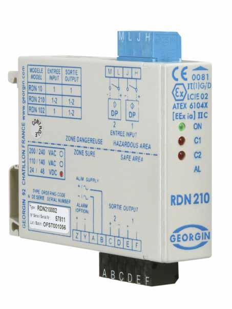
26 Ref. RDN Digital inputs - transistor outputs Description (see technical data sheet for further information) The RDN is an intrinsically safe, galvanic-isolated relay for switches or proximity sensors. The RDN powers switches in a hazardous area (8.2 V at 8 ma). Here the relay output (F E) is transistor, in contrast to the RDN110 (equipped with a relay). Number of Type channels Options Power supply RDN channel 1 transistor output 00 No alarm V AC AL With alarm V AC B0 Screw terminals 2 24/48 V DC BL Alarm + screw terminals 7 12 V DC - - Other options (see technical data sheet) IS parameters ATEX marking HJ terminals: Uo: 12 V Io: 25 ma Po: 150 mw Co: 1410 nf Lo: 45 mh RDN210 Green LED to indicate power is supplied to the module. Red LED to indicate that the output transistor is conductive. Red LED (AL) to indicate that the alarm transistor is conductive. It becomes conductive when the proximity sensor (Namur) input is outside of its operating range. Identical model to the RDN110 but with 1 input and 2 simultaneous outputs. Type RDN Number of channels channels 2 x 1 transistor outputs Options Power supply 00 No alarm V AC AL With alarm V AC B0 Screw terminals 2 24/48 V DC BL Alarm + screw terminals 7 12 V DC - - Other options (see technical data sheet) HJ terminals: Uo: 12 V Io: 25 ma Po: 150 mw Co: 1410 nf Lo: 45 mh Green LED to indicate power is supplied to the module. 2 x red LED to indicate that the output transistors (C1 and C2) are conductive. Red LED (AL) to indicate that the alarm transistor is conductive. The alarm is activated when one of the two proximity sensors (Namur) indicates a fault. Identical model to the RDN110 but with 1 input and 2 simultaneous outputs. Type RDN Number of channels channel 2 x 1 transistor outputs Options Power supply 00 No alarm V AC AL With alarm V AC HJ terminals: Uo: 12V Io: 25mA Po: 150mW Co: 1410 nf Lo: 45 mh RDN102 B0 Screw terminals 2 24/48 V DC BL Alarm + screw terminals 7 12 V DC - - Other options (see technical data sheet) Green LED to indicate power is supplied to the module. 2 x red LED to indicate activation of the simultaneous output relays (C1 and C2). Red LED (AL) to indicate that the alarm transistor is conductive. It becomes conductive when the proximity sensor (Namur) input is outside of its operating range. 24


27 Explanatory diagram I/O 1 Input / 2 transistor Outputs 2 Inputs / 2 transistor Outputs 1 Input / 1 transistor Output 25
28 Ref. RDN310 RDN Digital inputs - output relays with input memory Description (see technical data sheet for further information) The RDN310 is an intrinsically safe, galvanic-isolated bistable relay for switches or proximity sensors. It is used in the example shown opposite to interface stroke-end switches or proximity sensors on a solenoid valve. The benefit of this device is that it enables the last state detected on the input to be memorised on the output. When the first proximity sensor changes state, the RDN relay input detects this and the output relay also changes state. The output relay retains its state as long as the second RDN input does not detect a change of state by proximity sensor no. 2. Type Number of channels Options Power supply RDN Inputs - 1 Output 00 No alarm V AC Green LED to indicate power is supplied to the module. Red LED to indicate that the C1 output relay is excited. B0 Screw terminals V AC 2 24/48 V DC The RDN410 is an intrinsically safe, galvanic-isolated bistable relay for switches or proximity sensors. Identical to the RDN310, it has two channels (i.e. 4 inputs). Type Number of channels Options Power supply RDN Inputs - 2 Outputs 00 No alarm V AC B0 Screw terminals V AC Green LED to indicate power is supplied to the module. 2 x red LED to indicate that the output relays (C1 and C2) are excited. 2 24/48 V DC IS parameters ATEX marking HJ terminals: Uo: 8.6 V Io: 9 ma Po: 19 mw Co, IIC: 6200 nf Lo, IIC: 350 mh HJ terminals: Uo: 8.6 V Io: 9 ma Po: 19 mw Co, IIC: 6200 nf Lo, IIC: 350 mh 26


29 Explanatory diagram I/O 4 Inputs / 2 relay Outputs 2 Inputs / 1 relay Output 27
30 Ref. 8. Digital inputs - signal isolator Description (see technical data sheet for further information) The RDN213W is a digital signal isolator with two independent channels. This intrinsically safe, galvanic-insulated separator uses opto-isolators to transfer the signal from the hazardous area to the safe area. The module operates without a power supply: the voltage source comes from the hazardous area. IS parameters ATEX marking RDN310 Type Model Power supply Input Output RDN 213 Opto-isolator IS input / NIS output W 2 channels 00 Cage clamp terminals 3 24 V DC B0 Screw terminals 7 12 V DC 2 x red LED to indicate that the output transistors (opto-isolators) are conductive. 8 5 V DC Maximum current on intrinsic safety circuit: 100 ma RDN410 Identical to the RDN213W, the RDN213V has four independent channels. Type Model Power supply Input Output RDN 213 Opto-isolator IS input / NIS output V 4 channels 00 Cage clamp terminals 3 24 V DC B0 Screw terminals 7 12 V DC 4 x red LED to indicate that the output transistors (opto-isolators) are conductive. 8 5 V DC Maximum current on intrinsic safety circuit: 100 ma 28

31 Explanatory diagram I/O 4 Inputs / 4 Opto-isolator Outputs 2 Inputs / 2 Opto-isolator Outputs 29
32 Ref. BXNA1*** BXNAI2*** 9. Analog inputs - converter Description (see technical data sheet for further information) The BXNA1 is an intrinsically safe, galvanic insulated converter for actuators. It is used to transmit a 4/20 ma signal (or other depending on the model selected) to a hazardous area. Type Model Power supply Input Output BXNA1 00 No option V AC 00 4/20 ma 00 4/20 ma B0 Screw terminals V AC 02 0/5 ma 3 24 V DC 04 0/20 ma 4 48 V DC 08-10/+10V 11 0/5 V 13 0/10V XX Others on request Presence of voltage indicated by a green LED Adjustment potentiometers for the source and the curve of the 4/20 ma output. The BXNAI2 is an intrinsically safe, galvanic-insulated converter for intelligent actuators (HART protocol). Identical to the BXNA1, it is only available in a 4/20 ma / 4/20 ma version as it is dedicated to actuators that use the HART protocol. Type Model Power supply BXNAI2 00 No option V AC B0 Screw terminals V AC 3 24 V DC 4 48 V DC Presence of voltage indicated by a green LED Adjustment potentiometers for the source and the curve of the 4/20 ma output. IS parameters ATEX marking HJ terminals: Uo: 23.5 V Io: 97 ma Po: 560 mw Co, IIC: 132 nf Lo, IIC: 5 mh HJ terminals: Uo: 23.5 V Io: 97 ma Po: 560 mw Co, IIC: 132 nf Lo, IIC: 5 mh 30
33 Explanatory diagram I/O 1 Input / 1 Output 1 Input / 1 Output 31
34 Ref. BXNI1A 10. Analog output - isolator Description (see technical data sheet for further information) The BXNI1A is a passive, self-powered 4/20 ma signal isolator. It is used to send a 4/20 ma signal generated in a safe area into a hazardous area. When the signal is transferred from the safe area to the hazardous area, the transfer impedance specific to the BXNIA (see example on p ) must be taken into account. Number of Type channels Model Option BXNI 1 1 channel A1 Impedance: 510Ω 00 No option A2 Impedance: 450Ω B0 Screw terminals A3 A4 A5 A6 A7 Impedance: 390Ω Impedance: 330Ω Impedance: 270Ω Impedance: 281Ω Impedance: 300Ω IS parameters ATEX marking HJ terminals: See technical data sheet (depends on the version) BXNI2A Adjustment potentiometers of the 4/20 ma output curve (1 per channel). 2-channel version Type Number of channels Model Option BXNI 2 2 channels A1 Impedance: 510Ω 00 No option A2 Impedance: 450Ω B0 Screw terminals A3 A4 A5 A6 A7 Impedance: 390Ω Impedance: 330Ω Impedance: 270Ω Impedance: 281Ω Impedance: 300Ω HJ terminals: See technical data sheet (depends on the version) Adjustment potentiometers of the 4/20 ma output curve (1 per channel). 2-channel version Type Number of channels Model Option BXNI 4 4 channels A1 Impedance: 510Ω 00 No option A2 Impedance: 450Ω B0 Screw terminals A3 Impedance: 390Ω HJ terminals: See technical data sheet (depends on the version) BXNI4A A4 A5 A6 A7 Impedance: 330Ω Impedance: 270Ω Impedance: 281Ω Impedance: 300Ω Adjustment potentiometers of the 4/20 ma output curve (1 per channel). 32
35 Explanatory diagram I/O 4 Inputs / 4 Outputs 2 Inputs / 2 Outputs 1 Input / 1 Output 33


36 11. Impedance transfer table (BXNI*T and BXNI*A) Impedance values for each version of the BXNI BXNI version A1 A2 A3 A4 A5 A6 A7 T Impedance transfer Input impedance vs. output impedance 510 Ω 450 Ω 390 Ω 330 Ω 270 Ω 281 Ω 300 Ω 330 Ω Out. In. Out. In. Out. In. Out. In. Out. In. Out. In. Out. In. Out. In. Min Ω Max Ω

37 Example Each version of the BXNI has its own impedance value (see table of values opposite). It is imperative to calculate the voltage drop generated by the BXNI to validate that the device behind it will have a sufficient voltage. Also pay attention to the maximum load of 630Ω (BXNI + equipment) 35
38 Ref. BXNE**0*** 12. Digital outputs - 1 channel power supplies Description (see technical data sheet for further information) The BXNE is an intrinsically safe power supply. The BNXE**0 version provides constant power. It is not equipped with a remote control. Number of Type Model channels Options Power supply BXNE ** Voltage and output current (depending on curve) 0 1 channel Without remote control Green LED to indicate power is supplied to the module. 00 No option E 110 / 230 V AC B0 Screw terminals 2 24/48 V DC IS parameters ATEX marking LH terminals: See BXNE curves (depends on the version) BXNE**1*** The BXNE is an intrinsically safe power supply. The BXNE**1 version is equipped with a 24 V DC remote control (E+F-). A 24 V input voltage (E+F-) therefore actuates the relay, which actuates the output (L+H-). Type BXNE Model ** Voltage and output current (depending on curve) Number of channels 1 1 channel With one 24 V DC remote control Options Green LED to indicate power is supplied to the module. Red LED to indicate the activation of the 24 V DC remote control (E+F-) Power supply 00 No option E 110 / 230 V AC B0 Screw terminals 2 24/48 V DC LH terminals: See BXNE curves (depends on the version) The BXNE is an intrinsically safe power supply. The BXNE**A version is equipped with two 24 V DC remote controls (E+F-) and (C+D-). A 24 V DC voltage on (E+F-) or on (C+D-) activates the output (L+H-). Type Model Number of channels Options Power supply LH terminals: See BXNE curves (depends on the version) BXNE** A*** BXNE ** Voltage and output current (depending on curve) A 1 channel 2 x 24 V DC remote controls (OR function) 00 No option E 110 / 230 V AC B0 Screw terminals 2 24/48 V DC Green LED to indicate power is supplied to the module. 2 x red LED to indicate activation of the 24 V DC controls (1 LED per control). 36
39 Explanatory diagram I/O 1 channel with 2 x 24 V DC remote control (OR function) 1 channel with 1 x 24 V DC remote control 1 channel without remote control 37
40 Ref. BXNE**4*** 13. Digital outputs - 2-channel power supplies controlled by 24 V DC Description (see technical data sheet for further information) The BXNE is an intrinsically safe power supply. The BXNE**4 version provides constant power to both channels (L+H-) and (M+J-). It is not equipped with a remote control. Caution: The same power unit supplies both channels. The power specified on the BXNE curve is therefore shared by both channels. Number of Type Model channels Options Power supply BXNE ** Voltage and output current (depending on curve) 4 2 channels Without remote control Green LED to indicate power is supplied to the module. 00 No option E 110 / 230 V AC B0 Screw terminals 2 24/48 V DC IS parameters ATEX marking LH terminals: See BXNE curves (depends on the version) BXNE**2*** The BXNE is an intrinsically safe power supply. The BXNE**2 version is equipped with a 24 V DC remote control on each channel. A 24 V voltage on terminals (C+D-) actuates output (M+J-) A 24 V voltage on terminals (E+F-) actuates output (L+H-) Caution: The same power unit supplies both channels. The power specified on the BXNE curve is therefore shared by both channels. Type BXNE Model ** Voltage and output current (depending on curve) Number of channels 2 2 channels With two 24 V DC remote controls Options Power supply 00 No option E 110 / 230 V AC B0 Screw terminals 2 24/48 V DC LH terminals: See BXNE curves (depends on the version) Green LED to indicate power is supplied to the module. 2 x red LED to indicate activation of the 24 V DC controls (1 LED per control). The BXNE is an intrinsically safe power supply. The BXNE**3 version is equipped with a 24V DC remote control that actuates outputs alternately: either (L+H-) or (M+J-). Type Model Number of channels Options Power supply LH terminals: See BXNE curves (depends on the version) BXNE** 3*** BXNE ** Voltage and output current (depending on curve) 3 2 alternate channels With one 24 V DC remote control Green LED to indicate power is supplied to the module. Red LED to indicate the activation of the 24 V DC remote control (E+F-) 00 No option E 110 / 230 V AC B0 Screw terminals 2 24/48 V DC 38

41 Explanatory diagram I/O 2 channels with 1 x 24 V DC remote control 24 V DC 2 channels without remote control 2 channels with 2 x 24 V DC remote control 39
42 Ref. BXNE**C*** 14. Digital outputs - 2-channel power supplies controlled by contact Description (see technical data sheet for further information) The BXNE is an intrinsically safe power supply. The BXNE**C version is equipped with a relay remote control on each channel. A contact on terminals (C+D-) actuates output (M+J-) A contact on terminals (E+F-) actuates output (L+H-) Caution: The same power unit supplies both channels. The power specified on the BXNE curve is therefore shared by both channels. Type BXNE Model ** Voltage and output current (depending on curve) Number of channels C 2 channels With two contact remote controls Options Power supply 00 No option 2 24/48 V DC B0 Screw terminals IS parameters ATEX marking LH terminals: See BXNE curves (depends on the version) BXNE**D*** Green LED to indicate power is supplied to the module. 2 x red LED to indicate activation of the contact controls (1 LED per control). The BXNE is an intrinsically safe power supply. The BXNE**D version is equipped with a relay remote control that actuates outputs alternately: either (L+H-) or (M+J-). Type BXNE Model ** Voltage and output current (depending on curve) Number of channels D 2 alternate channels With 1 contact remote control Options Power supply 00 No option 2 24/48 V DC B0 Screw terminals Green LED to indicate power is supplied to the module. Red LED to indicate the activation of the contact remote control (E+F-) LH terminals: See BXNE curves (depends on the version) 40
43 Explanatory diagram I/O 2 channels with 2 contact remote controls 2 alternate channels with 1 contact remote control 41
: 160 Po (mw): 1300 Co II C (nf): 132 Lo II C (mh): 1 Co II B (nf): 980 Lo II B (mh): 5.")
: 130 Po (mw): 1100 Co II C (nf): 132 Lo II C (mh): 2 Co II B (nf): 980 Lo II B (mh): 8.")
: 87 Po (mw): 750 Co II C (nf): 132 Lo II C (mh): 4 Co II B (nf): 980 Lo II B (mh): 17")
: 980 Lo II B (mh): 6.5 BXNE04 Uo (V): 23.")
: 23.")
: 26.3 Io (ma): 80 Po (mw): 710 Co II C (nf): 97 Lo II C (mh): 5.")
44 15. Power curves and IS parameters (BXNE) BXNE01 Uo (V): 23.5 Io (ma): 160 Po (mw): 1300 Co II C (nf): 132 Lo II C (mh): 1 Co II B (nf): 980 Lo II B (mh): 5.5 BXNE03 Uo (V): 23.5 Io (ma): 130 Po (mw): 1100 Co II C (nf): 132 Lo II C (mh): 2 Co II B (nf): 980 Lo II B (mh): 8.5 BXNE05 Uo (V): 23.5 Io (ma): 87 Po (mw): 750 Co II C (nf): 132 Lo II C (mh): 4 Co II B (nf): 980 Lo II B (mh): 17 BXNE02 Uo (V): 23.5 Io (ma): 150 Po (mw): 1150 Co II C (nf): 132 Lo II C (mh): 1.5 Co II B (nf): 980 Lo II B (mh): 6.5 BXNE04 Uo (V): 23.5 Io (ma): 110 Po (mw): 900 Co II C (nf): 132 Lo II C (mh): 3 Co II B (nf): 980 Lo II B (mh): 11 BXNE06 Uo (V): 23.5 Io (ma): 78 Po (mw): 690 Co II C (nf): 132 Lo II C (mh): 6 Co II B (nf): 980 Lo II B (mh): 25 BXNE07 Uo (V): 26.3 Io (ma): 80 Po (mw): 710 Co II C (nf): 97 Lo II C (mh): 5.5 Co II B (nf): 740 Lo II B (mh): 17 BXNE08 Uo (V): 26.3 Io (ma): 105 Po (mw): 900 Co II C (nf): 97 Lo II C (mh): 3 Co II B (nf): 740 Lo II B (mh): 11 BXNE09 Uo (V): 23.5 Io (ma): 64 Po (mw): 590 Co II C (nf): 132 Lo II C (mh): 9 Co II B (nf): 980 Lo II B (mh): 32 BXNE10 Uo (V): 26.3 Io (ma): 40 Po (mw): 390 Co II C (nf): 97 Lo II C (mh): 25 Co II B (nf): 740 Lo II B (mh): 80 42
: 740 Lo II B (mh): 32 BXNE34 Uo (V): 13 Io (ma): 185 Po (mw): 1250")
: 6200 Lo II B (mh): 4 BXNE37 Uo (V): 16.")
: 2690 Lo II B (mh): 3 BXNE31 Uo (V): 7.")
: 240000 Lo II B (mh): 4 BXNE36 Uo (V): 13.")
: 10 BXNE41 Uo (V): 19.")
: 1490 Lo II B (mh): 0.4 BXNE42 Uo (V): 27.")
: 19 BXNE49 Uo (V): 24.")
45 BXNE11 Uo (V): 26.3 Io (ma): 70 Po (mw): 630 Co II C (nf): 97 Lo II C (mh): 9.5 Co II B (nf): 740 Lo II B (mh): 32 BXNE34 Uo (V): 13 Io (ma): 185 Po (mw): 1250 Co II C (nf): 1000 Lo II C (mh): 0.9 Co II B (nf): 6200 Lo II B (mh): 4 BXNE37 Uo (V): 16.1 Io (ma): 270 Po (mw): 2150 Co II C (nf): 451 Lo II C (mh): 0.9 Co II B (nf): 2690 Lo II B (mh): 3 BXNE31 Uo (V): 7.2 Io (ma): 185 Po (mw): 620 Co II C (nf): Lo II C (mh): 0.9 Co II B (nf): Lo II B (mh): 4 BXNE36 Uo (V): 13.1 Io (ma): 142 Po (mw): 600 Co II C (nf): 970 Lo II C (mh): 3 Co II B (nf): 6000 Lo II B (mh): 10 BXNE41 Uo (V): 19.5 Io (ma): 170 Po (mw): 1640 Co II C (nf): 240 Lo II C (mh): 0.1 Co II B (nf): 1490 Lo II B (mh): 0.4 BXNE42 Uo (V): 27.9 Io (ma): 76 Po (mw): 496 Co II C (nf): 84 Lo II C (mh): 5 Co II B (nf): 654 Lo II B (mh): 19 BXNE49 Uo (V): 24.1 Io (ma): 87 Po (mw): 496 Co II C (nf): 124 Lo II C (mh): 5 Co II B (nf): 920 Lo II B (mh): 19 BXNE50 Uo (V): 27.4 Io (ma): 112 Po (mw): 737 Co II C (nf): 87 Lo II C (mh): 2.5 Co II B (nf): 677 Lo II B (mh): 10 BXNE61 Uo (V): 15 Io (ma): 272 Po (mw): 7473 Co II C (nf): --- Lo II C (mh): --- Co II B (nf): 3550 Lo II B (mh):
: 109 Po (mw): 717 Co II C (nf): 87 Lo II C (mh): 2 Co II B (nf): 677 Lo II B (mh): 8 BXNE66 Uo (V): 25 Io (ma): 170 Po (mw): 1119 Co II C (nf): --- Lo II C (mh): --- Co II B (nf):")
: 170 Po (mw): 483 Co II C (nf): 5200 Lo II C (mh): 0.5 Co II B (nf): 43000 Lo II B (mh): 2 BXNE63 Uo (V): 19.3 Io (ma): 149 Po (mw): 697 Co II C (nf): 248 Lo II C (mh): 0.")
: 840 Lo II B (mh): 7 BXNE69 Uo (V): 25 Io (ma): 93 Po (mw): 552 Co II C (nf): 110 Lo II C (mh): 4 Co II B (nf): 840 Lo II B (mh): 16 BXNE71 Uo (V): 26.")
46 BXNE62 Uo (V): 11.2 Io (ma): 75 Po (mw): 197 Co II C (nf): 1840 Lo II C (mh): 5 Co II B (nf): Lo II B (mh): 19 BXNE64 Uo (V): 27.4 Io (ma): 109 Po (mw): 717 Co II C (nf): 87 Lo II C (mh): 2 Co II B (nf): 677 Lo II B (mh): 8 BXNE66 Uo (V): 25 Io (ma): 170 Po (mw): 1119 Co II C (nf): --- Lo II C (mh): --- Co II B (nf): 840 Lo II B (mh): 5 BXNE70 Uo (V): 27.9 Io (ma): 110 Po (mw): 733 Co II C (nf): 84 Lo II C (mh): 2 Co II B (nf): 654 Lo II B (mh): 8 BXNE73 Uo (V): 8.9 Io (ma): 170 Po (mw): 483 Co II C (nf): 5200 Lo II C (mh): 0.5 Co II B (nf): Lo II B (mh): 2 BXNE63 Uo (V): 19.3 Io (ma): 149 Po (mw): 697 Co II C (nf): 248 Lo II C (mh): 0.9 Co II B (nf): 1520 Lo II B (mh): 3.6 BXNE65 Uo (V): 25 Io (ma): 147 Po (mw): 887 Co II C (nf): 110 Lo II C (mh): 1.5 Co II B (nf): 840 Lo II B (mh): 7 BXNE69 Uo (V): 25 Io (ma): 93 Po (mw): 552 Co II C (nf): 110 Lo II C (mh): 4 Co II B (nf): 840 Lo II B (mh): 16 BXNE71 Uo (V): 26.8 Io (ma): 119 Po (mw): 766 Co II C (nf): 92 Lo II C (mh): 1.8 Co II B (nf): 720 Lo II B (mh): 7.2 BXNE74 Uo (V): 25 Io (ma): 68 Po (mw): 398 Co II C (nf): 110 Lo II C (mh): 8 Co II B (nf): 840 Lo II B (mh): 30 44
 = 100Ω x 0.")
: 15 Io (ma): 272 Po (mw): 3375 Co II C (nf): 580 Lo II C (mh): 0.")
47 16. Example of BXNE selection In this example, the intrinsic safety solenoid valve has an internal resistance R of 100Ω. And the current I required for the solenoid valve to operate correctly is 100 ma. Calculation of voltage U required for the solenoid valve to operate: U = R x I U(V) = 100Ω x 0.1 A U = 10 V Therefore, using the power curve below we must verify that the BXNE76 is suitable for this application: The BXNE must be capable of supplying 10 V at 100 ma. The point must therefore be located inside the curve. Intrinsic safety parameters: BXNE76 Uo (V): 15 Io (ma): 272 Po (mw): 3375 Co II C (nf): 580 Lo II C (mh): 0.3 Co II B (nf): 3550 Lo II B (mh): 3 The solenoid valve must also be compatible with the power supply in terms of intrinsic safety. See "Notions of intrinsic safety" chapter. 45
48 Ref. 17. Digital inputs - opto-isolator output signal isolator Description (see technical data sheet for further information) The RDN210W is an intrinsically safe, galvanic insulated digital signal separator. This device does not have an external power supply. The opto-isolator output transistors (H+J-) or (L+M-) are controlled by an input voltage (E+F-) for channel 1 and (C+D-) for channel 2. IS parameters ATEX marking RDN210W Type Model RDN 210 Opto-isolator IS input / NIS output Number of channels 2 W channels Options 00 Cage clamp terminals Power supply 3 24 V DC B0 Screw terminals 7 12 V DC Red LED for each channel indicating if the output transistor is conductive or closed. 8 5 V DC Maximum current on intrinsic safety circuit: 100 ma RDN210V The RDN210V is an intrinsically safe, galvanic insulated digital signal separator. Identical to the RDN210W, the RDN210V has four channels. Type Model RDN 210 Opto-isolator IS input / NIS output Number of channels 4 V channels Options 00 Cage clamp terminals Power supply 3 24 V DC B0 Screw terminals 7 12 V DC Red LED for each channel indicating if the output transistor is conductive or closed. 8 5 V DC Maximum current on intrinsic safety circuit: 100 ma 46

49 Explanatory diagram I/O 4 opto-isolator channels 2 opto-isolator channels 47
50 Ref. 18. Digital outputs - relay output signal isolator Description (see technical data sheet for further information) The RDN211W is an intrinsically safe, galvanic insulated digital signal separator. This device does not have an external power supply. The output relays (HJ) or (LM) are controlled by an input voltage (E+F-) for channel 1 and (C+D-) for channel 2. IS parameters ATEX marking RDN211W RDN211V Type Model RDN 211 Relay outputs IS input / NIS output Number of channels W 2 channels Options 00 B0 01 B1 Cage clamp terminals NO contact Screw terminals NO contact Cage clamp terminals NC contact Screw terminals NC contact Red LED for each channel indicating if the output relay is active or not. The RDN211V is an intrinsically safe, galvanic insulated digital signal separator. Identical to the RDN211W, the RDN211V has four channels. Type Model RDN 211 Relay outputs IS input / NIS output Number of channels V 4 channels Options 00 B0 Cage clamp terminals NO contact Screw terminals NO contact Cage clamp terminals NC contact Screw terminals NC contact Red LED for each channel indicating if the output relay is active or not. 01 B1 Power supply V AC V AC 3 24 V DC 4 48 V DC Power supply 3 24 V DC 4 48 V DC Maximum voltage on intrinsic safety circuit: 60 V Maximum current on intrinsic safety circuit: 100 ma 48

51 Explanatory diagram I/O 4 opto-isolator channels 2 opto-isolator channels 49
52 Ref. BXNR BXNC 19. Temperature inputs - converter Description (see technical data sheet for further information) The BXNR is a temperature converter dedicated to RTD100 2-wire or 3-wire probes. When ordering, specify the input scale and output. Type Input Option BXNR ** Input scale See technical data sheet Power supply Output 00 No option V AC 00 Active 4/20 ma B0 Screw terminals V AC 03 Active 0/20mA 3 24 V DC 08 0/5 V 4 48 V DC A0 Passive 4/20 ma Presence of voltage indicated by a green LED Adjustment potentiometers for the source and the curve of the 4/20 ma output The BXNC is a temperature converter dedicated to thermocouple probes. When ordering, specify the input scale and output. Type Input Option Power supply Output BXNC ** Input scale See technical data sheet XX Others on request 00 No option V AC 00 Active 4/20 ma B0 Screw terminals V AC 03 Active 0/20mA 3 24 V DC 08 0/5 V 4 48 V DC A0 Passive 4/20 ma Presence of voltage indicated by a green LED Adjustment potentiometers for the source and the curve of the 4/20 ma output XX Others on request IS parameters ATEX marking HJ terminals: Uo: 12.5V Io: 11mA Po: 66mW Co, IIC: 1200 nf Lo, IIC: 300 mh JL terminals: Uo: 12.5V Io: 12mA Po: 75mW Co, IIC: 1200 nf Lo, IIC: 200 mh HJ terminals: Uo: 12.5 V Io: 2.4 ma Po: 15 mw Co, IIC: 1200 nf Lo, IIC: 1000 mh 50
53 Explanatory diagram I/O 1 TC Input / 1 Output 1 RTD100 Input / 1 Output 51
54 Ref. BXNP 20. Potentiometer inputs - resistance-converter Description (see technical data sheet for further information) The BXNP is a converter for potentiometers. When ordering, specify the input scale and output. Type Input Option Power supply Output BXNP ** 0-1 KΩ to 0-50 KΩ 4 ma adjustable within 0-30% of the range 20 ma adjustable within % of the range 00 No option V AC B0 Active 4/20 ma B0 Screw terminals V AC 3 24 V DC ** Other on request 4 48 V DC IS parameters ATEX marking HJ terminals: Uo: 12.5 V Io: 80 ma Po: 600 mw Co, IIC: 1200 nf Lo, IIC: 5 mh JL terminals: Uo: 12.5 V Io: 2.4 ma Po: 15 mw Co, IIC: 1200 nf Lo, IIC: 1000 mh BXNRV Presence of voltage indicated by a green LED Adjustment potentiometers for the source and the curve of the 4/20 ma output The BXNRV is used to interface a 2-wire variable resistance. Type Input Option Power supply Output BXNC V1 V5 V6 4 ma adjustable between 270 and 330Ω 20 ma adjustable between 850 and 1700Ω 4 ma adjustable between 3900 and 5500Ω 20 ma adjustable between 8200 and 11200Ω 4 ma adjustable between 0 and 750Ω 20 ma adjustable between 6000 and 7500Ω 00 B0 No option Screw terminals V AC 110 V AC 00 Active 4/20 ma 03 Active 0/20mA 3 24 V DC 08 0/5 V ** Other on request 4 48 V DC A0 Presence of voltage indicated by a green LED Adjustment potentiometers for the source and the curve of the 4/20 ma output XX Passive 4/20 ma Others on request HJ terminals: Uo: 12.5 V Io: 11 ma Po: 66 mw Co, IIC: 1200 nf Lo, IIC: 300 mh 52
55 Explanatory diagram I/O 1 resistance Input / 1 Output 1 Pot. Input / 1 Output 53
56 Ref. BPX 21. Universal inputs - threshold relays Description (see technical data sheet for further information) The BPX is a programmable, galvanic-insulated converter with a universal input. Can be configured via PC using the ProgressX manager software and an RS232 serial cable. Optional Type Model Power supply Input Output terminal block BPX 0 NSI / NIS 00 Cage clamp E 1 SI / IS B0 Screw 2 98 to 255 V AC 21 to 53 V DC Inputs: Current (ma) -2.5 to +23 ma Voltage (mv) -10 to +105 mv Voltage (V) -1 to V Thermocouple J -210 to C Thermocouple K -250 to C Thermocouple B +400 to C Thermocouple R -50 to C Thermocouple S -50 to C Thermocouple T -250 to +400 C Thermocouple E** -270 to C Thermocouple N -240 to C Thermocouple W5-20 to C 2-wire PT 100 resistance 3-wire PT 100 resistance 4-wire PT 100 resistance 2/3/4-wire sensor +3.5 to +23 ma Potentiometer 0 to 100% of 1 KΩ to 20 KΩ 10 1 input 10 1 Output 4/20 ma 11 1 input + HART 1A 2D* 2G* 0C 0F 0B 0E 1 x 4/20 ma output 2 relays (inverters) 2 x 4/20 ma outputs 2 relays (Contact, NO) 2 x 4/20 ma outputs 2 relays (Contact, NC) 2 relays (Contact, NO) 2 relays (Contact, NC) 4 relays (Contact, NO) 4 relays (Contact, NC) Presence of voltage indicated by a green LED Micro-controller operation indicated by flashing green LED. Red LED to indicate activation of the output relays (depending on option selected). RS232 connection for configuration of BPX via PC Shunt to create Passive output only Indifferently active or passive output IS parameters ATEX marking Transmitter Z-X terminals: Uo: 27.9 V Io: 78.2 ma Po: mw Co, IIC: µf Lo, IIC: 2.8 mh Current XT terminals: Uo: V Io: 2.82 ma Po: 0.04 mw Co, IIC: 1000 µf Lo, IIC: 100 mh mv-v-tc-rtd100-pot WUSRPT terminals Uo: 7 V Io: 5.64 ma Po: 9.87 mw Co, IIC: µf Lo, IIC: 100 mh 54


57 Explanatory diagram I/O 1 Input / up to 2 x 4/20 ma outputs up to 4 relay outputs ProgressX manager software (BPX Configuration) 55
58

59 4. Use of galvanic insulation 57

60 1. Connection Please ensure you read all the instructions in the individual product manual and only start the installation work when you have understood everything. This manual is supplied with each product. It is also available on our website: These equipment items may receive hazardous voltages on their terminals. If you do not follow the instructions correctly, you may expose yourself and others to serious injury as well as damage to equipment. Before starting your installation, ensure that the model and power supply are suited to your purpose. This equipment should only be connected in accordance with applicable regulations by qualified personnel. Standard: plug-in cage clamp terminals (max. capacity 2.5 mm²) A flat head screwdriver (0.6 x 3.5 mm) is recommended to open the cage clamp terminal. Optional: plug-in screw terminals (max. capacity 2.5 mm²) 2. Installation The equipment is intended for association in accordance with intrinsic safety; the installation must be in compliance with standard EN , in particular paragraph Fixing and mounting The equipment is intended for installation on an EN rail attached horizontally on a vertical plane, in order to respect the direction of natural convection. Do not obstruct the air vents. Use a screwdriver to insert and remove the equipment as indicated. 4. Location The equipment must be installed in a non-explosive atmosphere, in a sound environment free of condensation and corrosive or conductive dust. Intrinsic safety is ensured in the operating temperature range specified in paragraph 1.6. However you should remember that the service life of electronic equipment is reduced by half when its temperature is increased by 10 C. You should therefore install the equipment in suitably ventilated equipment rooms, avoid the proximity of elements that may heat the equipment by radiation or which are likely to generate electromagnetic radiation greater than 10V/m. 5. Electrical connection Electrical connections must be made when the equipment is DE-ENERGIZED, using wires with a maximum diameter of 2.5 mm². For connections, refer to the wiring diagram. 6. Mechanical properties The intrinsic safety terminals must only be connected to intrinsic safety equipment or equipment which is in compliance with paragraph 5.7 of standard EN Moreover, the association of equipment and the connection cable must be compatible in terms of intrinsic safety. 58

61 7. Cable path The properties of cables and their routing from the ATEX zone (I.S. cables) must comply with the recommendations set out in paragraphs 6.1, and 6.3 of standard EN Full precautions must be taken to prevent electromagnetic disturbance with other cables that may generate dangerous voltages or currents. The I.S. cables must be clamped in order to prevent random contact with other cables in the event the terminal is shorn. 8. Adjustments and configuration See technical data sheet or instructions for use. 9. Maintenance Precautions to take during maintenance Dismounting must be carried out DE-ENERGIZED. In the event you suspect a failure or permanent fault, return the equipment to our services or representatives, who are the only maintenance providers certified to perform expert assessments or repairs. 10. Dismounting 59
62

63 5. according to type of assembly 61
64 1. Assembly methods Not covered in this guide. Our equipment features other assembly methods. See technical data sheet for further information. I/O Mounting DIN rail I.S. (Intrinsic Safety) Equivalent backplane mounting I.S. (Intrinsic Safety) Equivalent board mounting I.S. (Intrinsic Safety) AI BXNT6 - - BVNT AI BXMT - - BVMT AI BXLT - - BVLT AI BXNTI6 BETI LV0I BVLTI AI BXMTI - - BVMT AI BXLTI - - BVMTI AI BXNT1 BET LV0 BVNS AI - AO BXNI BEI DIC BVNI DI RDN110 BED110 CRN - DI RDN211 BED211 CRN - DI RDN112 BED112 CRN - DI RDN100 BED DI RDN210 BED DI RDN102 BED DI RDN310 / 410 BED310 / DI RDN213 V/W AO BXNA BEA LW0 BVNA AO BXNAI BEAI - BVNAI DO BXNE BEE CASI - DO RDN210 V/W DO RDN211V/W TI BXNR BER LXR BVNR TI BXNC BEC LXC BVNC PI BXNP BEP LXP BVNP RI BXNRV - - BVNRV UI BPX1 - LPX - CPX BPX0 Equivalent to mounting on DIN rail N.I.S (Non-Intrinsic Safety) 62
65

66 Imagined, designed and made in France Régulateurs GEORGIN France 14-16, rue Pierre Sémard - BP CHATILLON Cedex France Tel: +33 (0) Fax: +33 (0) regulateurs@georgin.com Belgium Temselaan 5-1 st floor STROMBEEK-BEVER Tel: Fax: info@georgin.be fc-interfaces-en Subject to modifications due to technical advances
SELECTION GUIDE. Interfaces galvanic insulation.
 SELECTION GUIDE Interfaces galvanic insulation 1. and notions of intrinsic safety 1. 4 2. Notions of intrinsic safety 7 2. 1. Mechanical properties 12 2. Certifications 12 3. Dimensions 12 3. Selection
SEM210 SERIES. Programmable In-head Universal Temperature Transmitter INDEX SECTION CONTENTS PAGE NO.
 INDEX SECTION CONTENTS PAGE NO. SEM210 SERIES 1.0 DESCRIPTION 1 2.0 SPECIFICATION 15 3.0 INSTALLATION 67 Programmable Inhead Universal Temperature Transmitter Status Instruments Ltd, Green Lane Business
Temperature Input Module for Zone 1 Series 9482/32
 www.stahl.de > 8 channels for temperature sensors > Intrinsically safe inputs Ex ia > For Pt-, Ni- and Cu-resistance temperature detectors according to DIN, IEC and GOST in 2-, 3- and 4-wire circuits >
3 Ex i Isolators. Temperature Transmitter with Output 0/ ma, without Limit Value Contact (Field Circuit Ex i) Type 9182/.0-5.
 Type 9182/.0-5.") Ex i Isolators Temperature Transmitter with Output 0/4... 20 ma, without Limit Value Contact Field Circuit Ex i) One unit for nearly all temperature sensors indivdually configurable Intrinsically safe
Ex i Isolators Temperature Transmitter with Output 0/4... 20 ma, without Limit Value Contact Field Circuit Ex i) One unit for nearly all temperature sensors indivdually configurable Intrinsically safe
Power supply. Calibration. Surface finishing. Seal. Process connection
 Page 1 of 6 Description The measuring system is designed for flow measurement. Gas flow through the sensing section passes two PT 100 RTD transducers; one is used as a temperature sensing device whilst
STT 3000 Series STT170 SMART TEMPERATURE TRANSMITTER Models STT171, STT173, STT17H, STT17F, STT17C
 STT 3000 Series STT170 SMART TEMPERATURE TRANSMITTER Models STT171, STT173, STT17H, STT17F, STT17C 34-TT-03-07 3/06 PRODUCT SPECIFICATION SHEET OVERVIEW The Honeywell STT170 series of programmable temperature
3 Ex i Isolators. Temperature Transmitter without Output 0/ ma, with Limit Value Contact (Field Circuit Ex i) Type 9182/.
 Type 9182/.") Ex i Isolators Temperature Transmitter without Output 0/4... 20 ma, with Limit Value Contact Field Circuit Ex i) One unit for nearly all temperature sensors indivdually configurable Intrinsically safe
Ex i Isolators Temperature Transmitter without Output 0/4... 20 ma, with Limit Value Contact Field Circuit Ex i) One unit for nearly all temperature sensors indivdually configurable Intrinsically safe
09746E00. ATEX / IECEx NEC 505 NEC 506 NEC 500 Class I Class I Class II Class III Zone Zone Division Ex i
 Temperature Transmitter Series 9182 www.stahl.de > One unit for nearly all temperature sensors indivdually configurable > Intrinsically safe input [Ex ia] IIC > Signal duplication possible > Galvanic isolation
Technical Information Barrier RB223
 TI00132R/09/EN/13.14 71275790 Products Solutions Services Technical Information Barrier RB223 One or two-channel barrier Loop-powered barrier for the safe separation of 4 to 20 ma standard signal circuits
Binary Output without Power Supply Series 9176
 Binary Output without Power Supply Series 9176 > For intrinsically safe operation of Ex i solenoid valves, indicators and horns > Power supply by control circuit, loop powered > Intrinsically safe output
STT 3000 Series STT170 SMART TEMPERATURE TRANSMITTER Models STT171, STT173, STT17H, STT17F, STT17C
 STT 3000 Series STT170 SMART TEMPERATURE TRANSMITTER Models STT171, STT173, STT17H, STT17F, STT17C 6/07 PRODUCT SPECIFICATION SHEET OVERVIEW The Honeywell STT170 series of programmable temperature transmitters
MODEL: B3HU. Space-saving Two-wire Signal Conditioners B3-UNIT
 Space-saving Two-wire Signal Conditioners B3-UNIT 2-WIRE UNIVERSAL TEMPERATURE TRANSMITTER (HART communication, intrinsically safe) Functions & Features Universal input: mv, V, T/C, RTD, resistance, potentiometer
RMA42. Technical Information
 Technical Information RMA42 Process transmitter with control unit Digital process transmitter for mounting on a top-hat rail for monitoring and visualizing analog measured values Application Plant and
Rev ECN Description Approval Date AA Release to Approvals RCS 10/9/12
 EB-20023137 Revision: AA Number of Pages: 13 Comments: Originator: RCS 10/05/12 Approved: RCS 10/05/12 Rev ECN Description Approval Date AA 1049085 Release to Approvals RCS 10/9/12 Micro Motion, Inc. Page
Operating Instructions
 Level and Pressure Operating Instructions VEGATOR 620, 621, 622 max. 0 10 min. 0 10 on VEGATOR 622! 6 7 8 9 10 11 12 13 14 in out Contents Contents Safety information... 2 Note Ex area... 2 1 Product description
TF 02 / TF 02-Ex. Head mounted temperature transmitters, FOUNDATION Fieldbus (H1), Pt 100 (RTD), thermocouples, 1 or 2 independent channels
, Pt 100 (RTD), thermocouples, 1 or 2 independent channels") TF 0 / TF 0-Ex Head mounted temperature transmitters, FOUNDATION Fieldbus (H), Pt 00 (RTD), thermocouples, or independent channels 0/-8.5 EN Input Resistance thermometer (,, wire circuit) Thermocouples
TF 0 / TF 0-Ex Head mounted temperature transmitters, FOUNDATION Fieldbus (H), Pt 00 (RTD), thermocouples, or independent channels 0/-8.5 EN Input Resistance thermometer (,, wire circuit) Thermocouples
Data Sheet KFD2-UFC-EX1.D. Supplied by. .com. Call us on +44 (0)
") Data Sheet KFD-UFC-EX1.D Supplied by.com Call us on +44 (0)118 916 940 Email info@47able.com Frequency Converter with Trip Values Features Assembly 1-channel isolated barrier 4 V DC supply (Power Rail)
Data Sheet KFD-UFC-EX1.D Supplied by.com Call us on +44 (0)118 916 940 Email info@47able.com Frequency Converter with Trip Values Features Assembly 1-channel isolated barrier 4 V DC supply (Power Rail)
Digital Input Output Module for Zone 2 Series 9470/33
 www.stahl.de > 16 channels can be adjusted in pairs as digital input or output > Intrinsically safe inputs/outputs Ex ia > For contacts, NAMUR proximity switches and low-power solenoid valves > Up to 8
Binary Output Series 9175
 Binary Output > Intrinsically safe output [Ex ia] IIC / [Ex ib] IIC > Galvanic isolation between input, output and power supply > Open-circuit and short-circuit monitoring (can be switched off) > For use
Isolators A3/1. Transmitter Supply Unit Field Circuit Ex i Series 9160 Rev. F
 Series 9160 Rev. F > Intrinsically safe input [Ex ia] IIC > Galvanic isolation between input, output and power supply > For use up to SIL 2, special version up to SIL 3 (IEC 61508) > High accuracy www.stahl.de
Inductive sensor slot-type SI2-K08-AP7
 SI2-K08-AP7 Slot sensor, height 8 mm Plastic, polypropylene Mechanical end stop, removable, for analog pointer instruments 3-wire DC, 10 30 VDC NO contact, PNP output Cable connection Wiring diagram Type
Digital temperature transmitter for resistance sensors Model T15.H, head mounting version Model T15.R, rail mounting version
 Temperature Digital temperature transmitter for resistance sensors Model T15.H, head mounting version Model T15.R, rail mounting version WIKA data sheet TE 15.01 for further approvals see page 10 Applications
MACX MCR-EX-T-UI-UP. Extract from the online catalog. Order No.:
 Extract from the online catalog MACX MCR-EX-T-UI-UP Order No.: 2865654 Freely programmable Ex-i temperature transducer with analog output and 1 limit value relay, standard configuration, resistance thermometer
Design and applications
 Design and applications The measuring device operates largely independent of viscosity and is suitable for indicating the flow rate of water, acids, alkaline solutions and gases. Every device is calibrated
Interfaces Galvanic Isolators Trip Amplifiers Converters:
 Interfaces between field mounted devices in explosive hazardous areas and non hazardous areas are useful to prevent a transfer of ignition energy from the non hazardous area into the explosive hazardous
Digital temperature transmitter Model T15.H, head mounting version Model T15.R, rail mounting version
 Electrical temperature measurement Digital temperature transmitter Model T15.H, head mounting version Model T15.R, rail mounting version WIKA data sheet TE 15.01 Applications Process industry Machine building
Laboratoire Central des Industries Electriques Une société de Bureau Veritas
 Laboratoire Central des Industries Electriques Une société de Bureau Veritas 33, avenue du Général Leclerc 92260 Fontenay-aux-Roses / FRANCE Tél : +33 1.40.95.60.60 ; Fax : +33 1.40.95.89.37 ; @ : www.lcie.fr
Digital Input Output Module 24 V for Ex n Zone 2 Series 9472/35
 www.stahl.de > 16 channels can be adjusted in pairs as digital inputs or outputs > Suitable for NAMUR proximity switches, 3-wire PNP proximity switches, contacts and solenoid valves (24 V / 0.5 A). > Up
Isolators A3/1. Vibration Transducer Supply Unit Series
 > For vibration, acceleration and speed sensors in 2- and 3-wire design > Space-saving dual-channel version > Signal frequencies up to 50 khz > Easy setting by means of front-side rotary switch > Galvanic
SET Installation and Operating Instructions. Level switch for two sensors
 Labkotec Oy Myllyhaantie 6 FI-33960 PIRKKALA FINLAND Tel: + 358 29 006 260 Fax: + 358 29 006 1260 20.2.2013 Internet: www.labkotec.fi 1/14 SET-2000 Level switch for two sensors Copyright 2013 Labkotec
MCR-FL-TS-LP-I-EX SIL IEC Programmable Intrinsically Safe Loop-Powered Temperature Measuring Transducer With HART Protocol
 SIL IEC 6 508 Programmable Intrinsically Safe Loop-Powered Temperature Measuring Transducer With HART Protocol Data Sheet 0068_en_03 PHOENIX CONTACT 0-07-09 Description Temperature FL ϑ Universal PC programmable
Technical Information RMA42
 TI00150R/09/EN/05.16 71315973 Products Solutions Services Technical Information RMA42 Process transmitter with control unit Digital process transmitter for monitoring and visualizing analog measured values
PRetrans Table of contents
 HART TRANSPARENT REPEATER PRetrans 5106 Table of contents Warnings 16 Safety instructions 17 EC Declaration of Conformity 19 How to demount SYSTEM 5000 20 Application 21 Technical characteristics 21 Mounting
Analog Universal Module HART for Zone 2 Series 9468/33
 > 8 channels can be adjusted individually as analog inputs or outputs > Intrinsically safe inputs/outputs Ex ia > For 0/4 20 ma + HART signals > Line fault monitoring per channel > Diagnostics based on
Installation guide 873 SmartRadar Control Unit & Antenna Unit
 Installation guide 873 SmartRadar Control Unit & Antenna Unit Rev. 7 January 2006 Part no. 4416.569 Enraf BV PO Box 812 2600 AV Delft Netherlands Tel. : +31 15 2701 100 Fax : +31 15 2701 111 E-mail : info@enraf.nl
Universal Intelligent 2-wire DIN Rail Transmitters
 Universal Intelligent 2-wire DIN Rail Transmitters IPAQ-L is a universal and intelligent 2-wire DIN rail transmitter for temperature and other measurement applications. IPAQ-LX is the Intrinsic Safe version
2-WIRE UNIVERSAL TEMPERATURE TRANSMITTER
 SAFE INSTALLATION MANUAL (FM APPROVAL) -WIRE UNIVERSAL TEMPERATURE TRANSMITTER (HART communication, intrinsically safe/explosion-proof) MODEL B6U/B6U-B BEFORE USE... SAFETY PRECAUTIONS This manual describes
0 2 1 â Ó. itemp HART TMT182. Technical Information
 Technical Information itemp HART TMT182 Temperature head transmitter Head transmitter for resistance thermometers (RTD), thermocouples (TC), resistance and voltage transmitters (mv), HART -protocol, for
Universal Intelligent 2-wire In-head Transmitters
 Universal Intelligent 2-wire In-head Transmitters Actual size IPAQ-H is a universal and intelligent 2-wire In-head transmitter for temperature and other measurement applications. IPAQ-HX is the Intrinsic
Head mounted Temperature Transmitter TF02/TF02-Ex
 Data Sheet Head mounted Temperature Transmitter TF0/TF0-Ex FOUNDATION Fieldbus H, Pt 00 (RTD), thermocouples, or independent channels Input Resistance thermometer (-, -, -wire circuit) Thermocouples Resistance
Isolators A3/1. Transmitter Supply Unit Field Circuit Ex i Series 9160
 Series 9160 > Intrinsically safe input [Ex ia] IIC > Galvanic isolation between input, output and power supply > For use up to SIL 2, special version up to SIL 3 (IEC 61508) > High accuracy www.stahl.de
R88000 T (including ATEX)
") INSTRUCTION MANUAL R88000 T88000 (including ATEX) Factory set transmitters are ready to use. Connect according the labels. Otherwise follow the calibration instructions. Input signals ṮC RTD CONTENTS:
INSTRUCTION MANUAL R88000 T88000 (including ATEX) Factory set transmitters are ready to use. Connect according the labels. Otherwise follow the calibration instructions. Input signals ṮC RTD CONTENTS:
Description. Annexe to: IECEx CML X Issue 1. Isolating Amplifier D461
 October 13, 2017 Annexe to: IECEx CML 15.0063X Issue 1 Applicant: Apparatus: Braun GmbH Isolating Amplifier D461 Description The Isolating Amplifier D461 is an intrinsic safety associated apparatus
Analog Input Module HART Ex i / I.S. Inputs, Channels Type 9461/
 > 4 channels for 2-wire HART transmitters and 4 channels for 4-wire HART transmitters > Intrinsically safe inputs Ex ia IIC > Galvanic separation between inputs and system > Open-circuit and short-circuit
OPTITEMP TT 10 C/R Technical Datasheet
 OPTITEMP TT 10 C/R Technical Datasheet Analogue 2-wire temperature transmitter Temperature linear 4...20 ma output Rangeable with solder pads and potentiometers Easy wiring through large center hole The
Temperature measurement TMD 832 head transmitter
 Technical information TI 062R/09/en Mat.-Nr. 510 00782 Temperature measurement TMD 832 head transmitter SMART head transmitter with HART protocol for RTD, Thermocouple and mv input signals Applications
Temperature Measurement
 Overview Application transmitters can be used in all industrial sectors. Due to their compact size they can be installed in the connection head type B (DIN 4729) or larger. The following sensors/signal
Universal Intelligent 2-wire DIN Rail Transmitters
 Universal Intelligent 2-wire DIN Rail Transmitters IPAQ-L is a universal and intelligent 2-wire DIN rail transmitter for temperature and other measurement applications. IPAQ-LX is the Intrinsic Safe version
MODEL: B6U-B B6-UNIT. [2] LCD DISPLAY 0: Without 1: With
![MODEL: B6U-B B6-UNIT. [2] LCD DISPLAY 0: Without 1: With](/thumbs/77/74906098.jpg "MODEL: B6U-B B6-UNIT. [2] LCD DISPLAY 0: Without 1: With") Field-mounted Two-wire Signal Conditioners B6-UNIT 8: TIIS flameproof (CE not available) Confirm selectable combinations of approval and wiring conduit types in the table. 2-WIRE UNIVERSAL TEMPERATURE
Field-mounted Two-wire Signal Conditioners B6-UNIT 8: TIIS flameproof (CE not available) Confirm selectable combinations of approval and wiring conduit types in the table. 2-WIRE UNIVERSAL TEMPERATURE
Expert 1400 / Expert 3400 Submersible Hydrostatic Level Transmitters
 Expert 1400 / Expert 3400 Submersible Hydrostatic Level Transmitters ll 2G EEx ia llc T6 As our products are continuously improved, we reserve the right to make any change in the stated specifications
06528E00. ATEX / IECEx NEC 505 NEC 506 NEC 500
 Switching Repeater Series 9170 > Intrinsically safe input [Ex ia] IIC > Galvanic isolation between input, output and power supply > Open-circuit / short-circuit monitoring and messaging (can be switched
Isolators A3/1.
 Temperature Transmitter Series 9182 > One unit for nearly all temperature sensors indivdually configurable > Signal duplication possible > Galvanic isolation between input, output, power supply and configuration
Isolators A3/1.
 > Compact limit value switch with 2 configurable limiting values and 4... 20 ma output > Suitable for 2-, 3-wire transmitters, 2-wire HART transmitters and ma sources > Intrinsically safe input [Ex ia]
Isolators A3/1. Transmitter Supply Unit Field Circuit Ex i Series
 Transmitter Supply Unit Series 9160 > Intrinsically safe input [Ex ia] IIC > Galvanic isolation between input, output and power supply > Open-circuit and short-circuit monitoring and messaging for input
Digital Input Output Module for Zone 1 Series 9470/32
 www.stahl.de > 16 can be adjusted in pairs as digital input or output > Intrinsically safe inputs/outputs Ex ia > For contacts, NAMUR proximity switches and low-power solenoid valves > Up to 8 can be used
Digital Temperature Transmitters Model T12.10, Universally Programmable, Head Mounting Model T12.30, Universally Programmable, Rail Mounting
 Electrical Temperature Measurement Digital Temperature Transmitters Model T12.10, Universally Programmable, Head Mounting Model T12.30, Universally Programmable, Rail Mounting WIKA Data Sheet TE 12.03
Installation guide 971 SmartRadar LTi
 Installation guide 971 SmartRadar LTi March 2009 Part no. 4416.715 Revision 3 Enraf B.V. P.O. Box 812 2600 AV Delft Netherlands Tel. : +31 15 2701 100 Fax : +31 15 2701 111 E-mail : enraf-nl@honeywellenraf.nl
Digital Input Output Module for Zone 2 Series 9470/33
 www.stahl.de > 16 can be adjusted in pairs as digital input or output > Intrinsically safe inputs/outputs Ex ia > For contacts, NAMUR proximity switches and low-power solenoid valves > Up to 8 can be used
Remote I/O. 74 Remote I/O. Remote I/O System
 System Overview of the System Components IS1+ 76 General Information IS1+ 77 CPU & Power Modules CPU & Power Modules for Zone 1 / Div. 1 IS1+ 9440/22 78 Sockets for CPU & Power Module IS1+ 9490 78 CPU
STT 3000 Smart Temperature Transmitter Series STT170 Specifications
 STT 3000 Smart Temperature Transmitter Series STT170 Specifications Model STT171, STT173, STT17H, STT17F, STT17C 34-TT-03-07 November 2010 Overview STT17H Features The Honeywell STT170 series of programmable
Rail mounted Temperature Transmitter TH102/TH102-Ex
 Data Sheet 10/-8.54 EN Rail mounted Temperature Transmitter TH102/TH102-Ex HART programmable, Pt 100 (RTD), thermocouples, electrical isolation Input Resistance thermometer (2, 3, 4 wire circuit) Thermocouples
User manual. Load cell with one built in amplifier KOSD-FA KIMD-FA KEND-FA Load cell with two built in amplifiers KOSD-FAD KIMD-FAD KEND-FAD
 User manual Load cell with one built in amplifier KOSD-FA KIMD-FA KEND-FA Load cell with two built in amplifiers KOSD-FAD KIMD-FAD KEND-FAD Contents Precautions Intended use General 1 Specification 3
Engineering Guideline. pac-carriers Type for Yokogawa Centum VP
 Engineering Guideline pac-carriers Type 9195 for Yokogawa Centum VP pac-carrier Type 9195 2 Engineering Guideline / Yokogawa Centum VP 26.0.2018 pac-carrier Type 9195 Integrated solutions for Yokogawa
Rev ECN Description Approval Date AA Release to Approvals RCS 10/9/12
 EB-20023139 Revision: AA Number of Pages: 13 Comments: Originator: RCS 10/05/12 Approved: RCS 10/05/12 Rev ECN Description Approval Date AA 1049085 Release to Approvals RCS 10/9/12 Micro Motion, Inc. Page
SBEx-2S BINARY SEPARATOR
 SBEx2S BNARY SEPARATOR accompanying device of group of category (M1), group i category (1), two channels in one rail housing (TS35, width 22.5mm), level ia intrinsically safe input circuits compliance
SITRANS T measuring instruments for temperature
 Overview Our field devices for heavy industrial use HART, Universal 4 to 20 ma, universal Field indicator for 4 to 20 ma signals The temperature transmitter SITRANS TF works where others feel uncomfortable.
DIN Rail Devices. CEAG Sicherheitstechnik GmbH 194
 DIN Rail Devices Description DIN rail devices serve as low cost signal conditioning modules between the field device and the control system. The new enclosures mounted on the 35 mm standard rail are equipped
Transducer transmitter BILT 4 II 2(1) G. Technical Manual
 G. Technical Manual") GB Transducer transmitter BILT 4 II 2(1) G Technical Manual Transducer transmitter BILT 4 Contents Introduction General... 3 Ex.safety description... 4 Technical data... 5 Installation General... 6 Mechanical
GB Transducer transmitter BILT 4 II 2(1) G Technical Manual Transducer transmitter BILT 4 Contents Introduction General... 3 Ex.safety description... 4 Technical data... 5 Installation General... 6 Mechanical
FieldIT Temperature Transmitter, rail mounted TH102/TH102-Ex
 Data Sheet 10/-8.54 EN Level 0: Information FieldIT Temperature Transmitter, rail mounted TH102/TH102-Ex HART programmable, Pt 100 (RTD), thermocouples, electrical isolation Resistance thermometer (2,
User manual. Load cell with one built in amplifier KOSD-FA KIMD-FA KEND-FA Load cell with two built in amplifiers KOSD-FAD KIMD-FAD KEND-FAD
 User manual Load cell with one built in amplifier KOSD-FA KIMD-FA KEND-FA Load cell with two built in amplifiers KOSD-FAD KIMD-FAD KEND-FAD Contents Precautions Intended use General 1 Specification 3
Digital Input Module 24 V Ex n Inputs, 16 Channels Series 9471
 > 16 channels for active 0 / 24 V signals > Zone 2 / Division 2 version for connection of circuits acc. to Ex nl, Ex na, Nonincendive and Non-Ex > Galvanic separation between inputs and system > Two channels
0 2 1 â Ó. itemp HART TMT182. Technical Information
 Technical Information itemp HART TMT182 Temperature head transmitter Head transmitter for resistance thermometers (RTD), thermocouples (TC), resistance and voltage transmitters (mv), HART -protocol, for
Operator Manual. Transmitters Series KAT-... Analog transmitters in 2-wire technique
 Operator Manual Transmitters Series KAT-... Analog transmitters in 2-wire technique Important Safety Notes! In the case of non-observance of the installation and safety notes or improper use of the transmitter
Temperature transmitter itemp PCP DIN rail TMT 121
 Technical information TI 087R/09/en 510 03671 Temperature transmitter itemp PCP DIN rail TMT 121 Universal temperature transmitter for resistance thermometers (RTD), thermocouples, resistance and voltage
Assembly. Front view. Power Rail
 Thermometer Resistance Repeater Features Assembly 1-channel isolated barrier 24 V DC supply (Power Rail) RTD/resistance input Resistance output Accuracy 0.1 % Front view Removable terminals blue Function
Digital temperature transmitter with HART protocol Model T32.1S, head mounting version Model T32.3S, rail mounting version
 Electrical temperature measurement Digital temperature transmitter with HART protocol Model T32.1S, head mounting version Model T32.3S, rail mounting version WIKA data sheet TE 32.04 Applications Process
Isolators A3/1. Temperature Transmitter Field Circuit Non-Ex i Series
 Temperature Transmitter Series 9182 > One unit for nearly all temperature sensors indivdually configurable > Signal duplication possible > Galvanic isolation between input, output, power supply and configuration
R24 DISPLAY MODULE WITH ACTIVE OUTPUT AND RELAY
 Čapkova 22 678 01 Blansko tel.: +420 516 416942, 419995 fax: +420 516 416963 R24 DISPLAY MODULE WITH ACTIVE OUTPUT AND RELAY Display module is designed for measuring the resistance, the signal from the
C520 / C520X /C520S / C520XS HART Compatible, Universal, Dual-input 2-wire Transmitters
 C520 / C520X /C520S / C520XS HART Compatible, Universal, Dual-input 2-wire Transmitters The 520 transmitters are universal, isolated, dual-input temperature transmitters with additional voltage and resistance
Digital Input Module NAMUR Ex i / I.S. Inputs, 16 Channels for Zone 1 / Div. 1 Series 9470/22
 www.stahl.de > 16 channels for contacts and NAMUR proximity switches (EN 60947-5-6) > Intrinsically safe inputs Ex ia IIC > Galvanic separation between inputs and system > Open-circuit and short-circuit
MINI MCR-SL-UI-I-LP-NC
 2-way isolation amplifier Data sheet 105263_en_02 PHOENIX CONTACT 2013-12-13 1 Description The configurable 2-way isolation amplifiers are used to electrically isolate, convert and filter standard signals.
3 Ex i Isolators. Switching Repeater with Power Relay (250 V / 4 A) Type 9170/ Type 9170/
 Type 9170/ Type 9170/") 3 Ex i Isolators Switching Repeater with Power Relay Intrinsically safe input [Ex ia] IIC Galvanic isolation between input, output and power supply Open-circuit / short-circuit monitoring and messaging
3 Ex i Isolators Switching Repeater with Power Relay Intrinsically safe input [Ex ia] IIC Galvanic isolation between input, output and power supply Open-circuit / short-circuit monitoring and messaging
IECEx Hazardous Area Approvals Fisher FIELDVUE DVC6200 Series Digital Valve Controllers
 Instruction Manual Supplement DVC6200 Digital Valve Controllers IECEx Hazardous Area Approvals Fisher FIELDVUE DVC6200 Series Digital Valve Controllers SIS Hazardous Area Approvals and Special Instructions
itemp HART DIN rail TMT112
 Temperature transmitter itemp HART DIN rail TMT112 Universal temperature transmitter for resistance thermometers (RTD), thermocouples, resistance and voltage transmitters, incorporating HART protocol Application
itemp PA TMT184 Technical information
 Technical information itemp PA TMT184 Temperature head transmitter with PROFIBUS-PA interface. Supply and digital communication using PROFIBUS-PA, for installation in a Form B sensor head. Features and
Positioner with HART Communication Type 3780
 Positioner with HART Communication Type 780 Application Single-acting or double-acting positioner for attachment to pneumatic control valves. Supplied with an electric input signal from to 20 ma Travels
Isolating Repeater Input Series 9163
 > For 4-wire HART transmitters and voltage sources > Intrinsically safe input [Ex ia] IIC > Galvanic isolation between input, output and power supply > For use up to SIL 2 (IEC 61508) > High accuracy www.stahl.de
... for hydraulic and general applications in hazardous areas
 ATEX Approved Inductive... for hydraulic and general applications in hazardous areas Inductive Namur sensors Explosion protected Ignition class "intrinsically safe" when used together a suitable certified
Installation guide 877 FDI Field Display & Interface
 Installation guide 877 FDI Field Display & Interface November 2008 Part no. 4416.264 Rev. 5 Enraf BV PO Box 812 2600 AV Delft Netherlands Tel. : +31 15 2701 100 Fax : +31 15 2701 111 E-mail : enraf-nl@honeywell.com
Two-channel safety barriers Series 9002
 Two-channel safety s Series 00 > Wide product range for all standard applications of the automation > Flexible and space-saving available in single and double channel versions > Time-saving installation
TÜV NORD CERT. TÜV NORD CERT GmbH & Co. KG Am TÜV 1 D Hannover. Annexe to IECEx TUN , issue No. 0 Page 1 of 5.
 GmbH & Co. KG Page 1 of 5 Electrical data: Base devices for 6DR50**-*****-**** Motherboard L250 Power supply / control current 4-20 ma... series connection (terminals 6+ and 7/8) 2-wire circuit with Hart
KFS. Flap-type flow meter. Design and range of application
 Design and range of application The measuring device operates largely independent of viscosity and is suitable for indicating the flow rate of water, acids, alkaline solutions and gases. Every device is
JUMO dtrans T02 Programmable 4-wire Transmitter (Smart Transmitter)
") JUMO GmbH & Co. KG Delivery address: Mackenrodtstraße 14 36039 Fulda, Germany Postal address: 36035 Fulda, Germany Phone: +49 661 6003-0 Fax: +49 661 6003-607 E-mail: mail@jumo.net Internet: www.jumo.net
JUMO GmbH & Co. KG Delivery address: Mackenrodtstraße 14 36039 Fulda, Germany Postal address: 36035 Fulda, Germany Phone: +49 661 6003-0 Fax: +49 661 6003-607 E-mail: mail@jumo.net Internet: www.jumo.net
HART Compatible Intelligent 2-wire In-head Transmitters
 HART Compatible Intelligent 2-wire In-head Transmitters Actual size MESO-H is a Smart and universal 2-wire Inhead transmitter for temperature and other measurement applications. MESO-HX is the Intrinsic
IPAQ C520 / C520X R520 / R520X. HANDBOOK / User Manual
 IPAQ C520 / C520X R520 / R520X HANDBOOK / User Manual IMPRINT C520/C520X / R520/R520X Copyright All rights reserved. Any duplication of this documentation or extracts thereof by any means is prohibited
C330 / C330X PC-Programmable Universal, 2-wire Transmitter
 C330 / C330X PC-Programmable Universal, 2-wire Transmitter The IPAQ C330 transmitter is a universal, isolated, temperature transmitter with additional voltage and resistance input. Its robust design and
Intrinsically Safe Compact Controller CTR 210i. Intrinsically Safe Bargraph Indicator. BGI 210i
 Intrinsically Safe Compact Controller CTR 210i Intrinsically Safe Bargraph Indicator BGI 210i DMT 02 ATEX E 148 2. Supplement also grahics display Revision 4 IBS BatchControl GmbH Im Sträßchen 2 4 Tel.:
JUMO dtrans T01 HART / T01T HART / T01 Junior / T01 Ex / T01 HART Ex Programmable 2-wire transmitter
 JUMO GmbH & Co. KG Delivery address: Mackenrodtstraße 14 36039 Fulda, Germany Postal address: 36035 Fulda, Germany Phone: 49 661 60030 Fax: 49 661 6003607 Email: mail@jumo.net Internet: www.jumo.net JUMO
Nivotester FTR325. Technical Information. 1-channel switch amplifier for the Soliwave M microwave barrier
 Technical Information Nivotester FTR325 1-channel switch amplifier for the Soliwave M microwave barrier Area of application The Nivotester FTR325 is suitable as a 1-channel switch amplifier for the Soliwave
IPAQ C530/R530 Technical Datasheet
 IPAQ C530/R530 Technical Datasheet Smart 2-wire universal transmitter with HART 7 and NFC technology NFC - Configuration of the transmitter via a portable device such as a smartphone. HART 7 protocol High