The Radio Technology Museum. The Early Days
|
|
|
- Cody Ford
- 6 years ago
- Views:
Transcription
1 The Radio Technology Museum New Displays The Early Days
2 In the Beginning
3 In the Beginning
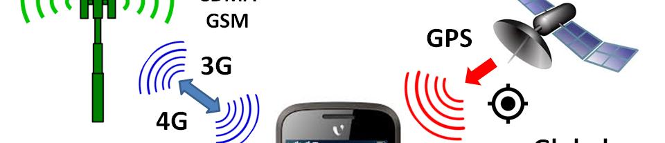
4 The Information Age
5

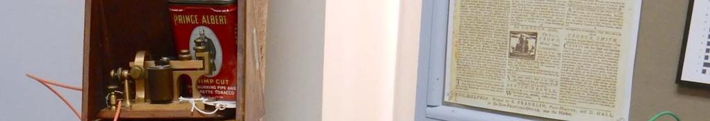
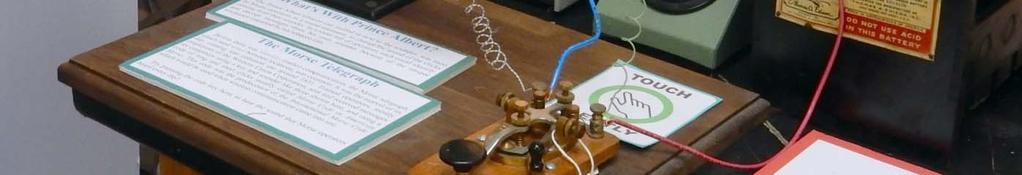
6 Morse Telegraph


7
8 Electro Magnetic Waves


9 Electromagnetic Waves CarryEnergy through Space Frequency and Wavelength FREQUENC Y ELECTRIC FIELD MAGNETIC FIELD ALTERNATING CURRENT (IN ANTENNA) 5/12/2016 How far does the wave travel for one cycle of the field? f C SPEEDOFLIGHT FREQUENCY Al Klase N3FRQ ,000,000meters/second cycles/ second(hertz)


10 THE RADIO SPECTRUM Each higher frequency band can carry ten times more information than the one to its left! 5/12/2016 Al Klase N3FRQ 2016


")


11 Antennas Launch and Intercept trdi Radio Waves Heinrich Hertz HALF WAVE DIPOLE VOLTAGE SPARK GAP TRANSMITTER (and antenna) CURRENT * 1 METER 2 1meter f C 5/12/2016 Al Klase N3FRQ 2016 C 2 150megahertz

12 Guglielmo Marconi QUARTER WAVE VERTICAL 40 meters English Channel station at the Haven Hotel, UK in August 1908 with the original 120ft mast. C C 40 meters 1875kil 4 f kilohertz /12/2016 Al Klase N3FRQ 2016
13 ANTENNAS INSIDE MODERN MOBILE DEVICES Higher frequency allows shorter more manageable antennas. WiFi Dipole 2.5 GHz Half Wave = 62.5 mm Cellphone Antenna Antenna Frequencies: Wifi/Bluetooth 2400 Mhz UMTS 2100 MHz GSM 850/900/1800/1900 MHz 42 mm = 1.7 5/12/2016
14 Wireless Telegraphy
15 Wireless Station ca Spark Gap Coherer Detector Morse Inker Key Guglielmo Marconi at the key. 5/12/2016 Al Klase N3FRQ 2016 Induction Coil

 RADIO-REQUENCY GENERATOR")

16 A SIMPLE RADIO SYSTEM ELECTRO-MAGNETIC WAVES ANTENNA ANTENNA POWER SUPPLY SOUND WAVES INFORMATION IN (ON-OFF KEYING) RADIO-REQUENCY GENERATOR DETECTOR INFORMATION OUT RADIO-REQUENCY CURRENT AUDIO-REQUENCY CURRENT RADIO ARCHITECTURE
17 Spark Transmitter
18 Simple Receiver RF amplification and AVC in Magic Box make this work well for the inexperienced operator.


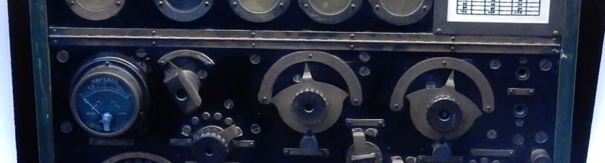
19 Marconi Transmitter, Poldhu, Wales - ca Oscillation Transformer Antenna Loading Coil 25 KW Alternatort Capacitors Rotary Gap in Soundproof Box 5/12/2016 Al Klase N3FRQ 2016 Rotary Gap In Action
20 50 KW Synchronous-Gap Spark Transmitter Societe Francaise Radioelectrique 5/12/2016 Al Klase N3FRQ 2016


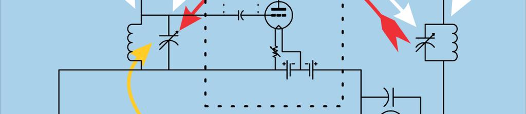
21 Poulsen Arc Continuous-Wave Transmitter Vladimir Poulsen with small arc converter. The DC arc has negative resistance causing the LC circuit to oscillate. 5/12/2016 Al Klase N3FRQ KW Federal Telegraph Co. Arc Transmitter

 turns high")
 producing 200")

22 Alexanderson Alternator Continuous-Wave Transmitter AC Motor (left) turns high frequency alternator (center) producing 200 KW in the frequency range of KHz. 5/12/2016 Al Klase N3FRQ 2016
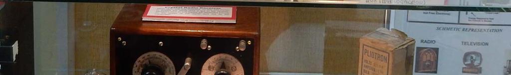
23 Early Semiconductors

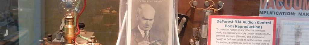
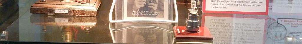
24 Early Vacuum Tubes
25
26
27 Armstrong and the Dawn of the Electronic Age
28


29
30 Discovery of Regemeration MCC (Marconi Cape Cod) Simulated Spark Transmitter Sending 1912 press (Live Demo)


")
31 Virtual Ether Stations Heard by Armstrong and Sarnoff at Belmar 31 Jan 1914 (Live Demo)


32 Damped Waves: Produced by spark gap gptransmitters. Each spark discharge causes the RF tuned circuit to ring like a bell or plucked string. Each pulse dies away. The carrier wave is inherently amplitude modulated at the spark frequency. At the receiver, detection in easily accomplished with a simple rectifier. 10 KHz 100 KHz 500 KHz 1 MHz 10 MHz Time Domain -> Frequency Domain -> Very wide bandwidth 5/12/2016 Al Klase N3FRQ 2016


33 Continuous Waves: Greater efficiency due to narrow bandwidth. Produced dby: High Frequency rotating machinery, e.g.the Alexanderson Alternator Poulsen Arc Converter Vacuum Tube or Solid State Oscillators Time Domain -> Frequency Domain -> 5/12/2016 Al Klase N3FRQ 2016
34
")


35 Amplitude Modulation: Produced by modulating a continuous wave (CW) source: High Frequency rotating machinery, e.g. the Alexanderson Alternator Poulsen Arc Converter Vacuum Tube or Solid State Oscillators Frequency Domain -> 500KHz modulated by 4KHz Time Domain -> 60KHz modulated by 4KHz Detection: Bottom half of the waveform has been clipped off by detector diode, a rectifier. Recovered audio, after audio filtering, shown in blue. 5/12/2016 Al Klase N3FRQ 2016


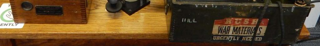
36 Military Electronics 1914 Spark transmitters and crystal sets
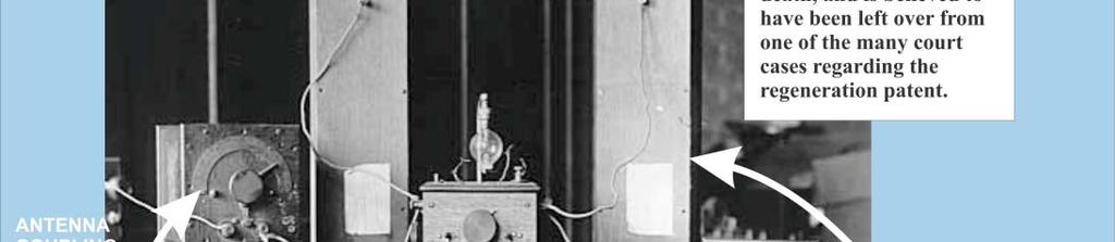
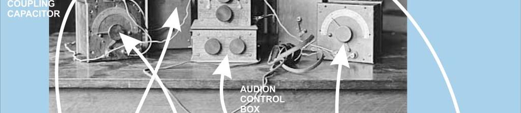
37 Navy Equipment at Belmar 1918 (Howeth) Two audion control boxes Two audion control boxes Receiver 2 stage audio amplifier
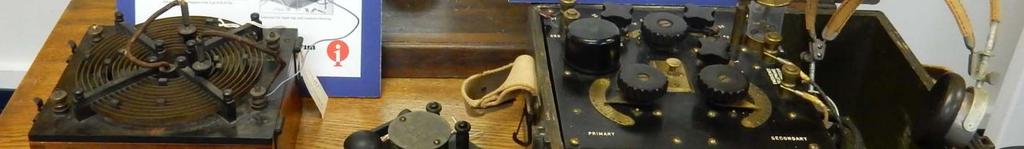
38 Navy Equipment at Belmar 2016
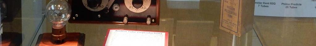
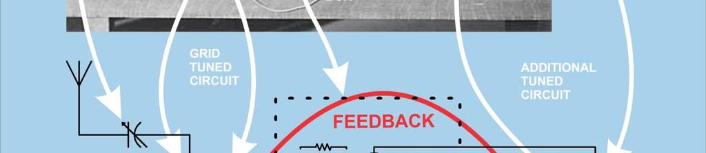
39 U.S. Navy SE-143 (CN-208) Radio Receiver Designed ca Washington Navy Yard and National Electric Supply ppy Co. A double-tuned receiving transformer with variable coupling Frequency range: KHz Connections for external crystal detector or audion (vacuum tube) to comprise a complete radio receiver. Tickler feedback connection to implement Armstrong regenerative detector. Capable of receiving continuous-wave (CW) telegraphy in the autodyne (oscillating) mode.. Early U.S. Navy Audion Control Box (Likely Model SE 838) Connects to tuner to form a regenerative receiver Oii Originally used CW 186 tube (Western Electric 201A )
40


41 Military Electronics 1918 Portable Continuous Wave Transmitter Receivers Radio Telephone Systems Long Range Radio Telephone Transmitters Based on mass produced vacuum tubes

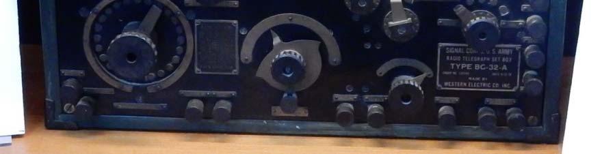
42 BC 32A CW Radio


43 CW-936 RADIO-TELEPHONE SYSTEM THE SUBCHASER SET Designed by Western Electric First commercially produced radio-telephone system Mic and loudspeaker on the bridge for quick communications 2-tube AM transmitter 3-tube receiver Five preset frequencies KHz 3-tube audio amplifier Loud-speaking telephone


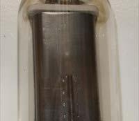
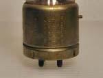
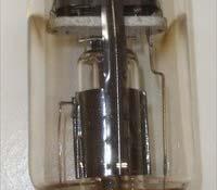
44 EARLY U.S. MILITARY VACUUM TUBES
45 Early Broadcasting Demos 1921 Westinghouse RC and Aeriola Junior
46 Early Broadcasting Demos 1924 Atwater Kent Model 20C
47 Operating Demos at RTM Morse Telegraph Two Stations w/poles and insulators Code practice sets Titanic Spark, Modern CW Candle stick dial telephone Spark Transmitter Tuning in Demo Original Armstrong Regen Virtual Ether Westinghouse RC Atwater Kent Model 20 C 1930 s Philco Console Hammarlund SP 600 R 390A with modulation monitor scope
48 Operating Demos at RTM Edison Gramophone Victrola Edison Diamond Disk machine Several 45 s (Phil wrote the book.) MonoHi Fi FisherTuner & Preamp, Heathkit Williamson amp, Altec Duplex speaker in Klipsch corner cabinet RCA 630 TV Dumont 21 TV 1948 ADSB Virtual Radar 1939 Philco console w/ Mystery Control (wireless remote) EE 8 field phones via BD 71 switchboard BC 348 receiver WWII Navy moral receiver
49 Cable Radio at RTM BROADBAND LF-MF-HF ANTENNA 75-OHM COAX TO DISPLAYS WRTM TRANSMITTER (GOLDEN OLDIES) DISTRIBUTION AMPLIFIER
Amateur Wireless Station Operators License Exam
 Amateur Wireless Station Operators License Exam Study material 2017 South India Amateur Radio Society, Chennai CHAPTER 5 1 Chapter 5 Amateur Wireless Station Operators License Exam Study Material Chapter
History of Naval Ships Wireless Systems I s to the 1920 s
 History of Naval Ships Wireless Systems I 1890 s to the 1920 s Wireless telegraphy was introduced in to the RN in 1897 by Marconi and Captain HB Jackson, a Torpedo specialist. There was no way to measure
Definitions of Technical Terms
 Definitions of Technical Terms Terms Ammeter Amperes, Amps Band Capacitor Carrier Squelch Diode Dipole Definitions How is an ammeter usually connected = In series with the circuit What instrument is used
California State University, Northridge Department of Electrical & Computer Engineering. Senior Design Final Project Report.
 California State University, Northridge Department of Electrical & Computer Engineering Senior Design Final Project Report FM Transmitter Josh Rothe Jonathan Rodriguez Pattrawut Phochana Jamell Jordan
PRINCIPLES OF COMMUNICATION SYSTEMS. Lecture 1- Introduction Elements, Modulation, Demodulation, Frequency Spectrum
 PRINCIPLES OF COMMUNICATION SYSTEMS Lecture 1- Introduction Elements, Modulation, Demodulation, Frequency Spectrum Topic covered Introduction to subject Elements of Communication system Modulation General
Chapter-15. Communication systems -1 mark Questions
 Chapter-15 Communication systems -1 mark Questions 1) What are the three main units of a Communication System? 2) What is meant by Bandwidth of transmission? 3) What is a transducer? Give an example. 4)
Test Equipment. PHYS 401 Physics of Ham Radio
 Test Equipment Voltmeter - an instrument that is used to measure voltage. It is used in parallel with a circuit to be measured. a series resistor extends the range of the meter. Ammeter - an instrument
Radio Receivers. Al Penney VO1NO
 Radio Receivers Al Penney VO1NO Role of the Receiver The Antenna must capture the radio wave. The desired frequency must be selected from all the EM waves captured by the antenna. The selected signal is
COMM 704: Communication Systems
 COMM 704: Communication Lecture 1: Introduction Dr. Mohamed Abd El Ghany, Mohamed.abdel-ghany@guc.edu.eg Course Objective Give an introduction to the basic concepts of electronic communication systems
Amateur Wireless Station Operators License Exam
 Amateur Wireless Station Operators License Exam Study material 2017 South India Amateur Radio Society, Chennai CHAPTER 4 1 Chapter 4 Amateur Wireless Station Operators License Exam Study Material Chapter
INTRODUCTION TO COMMUNICATION SYSTEMS AND TRANSMISSION MEDIA
 COMM.ENG INTRODUCTION TO COMMUNICATION SYSTEMS AND TRANSMISSION MEDIA 9/9/2017 LECTURES 1 Objectives To give a background on Communication system components and channels (media) A distinction between analogue
EE301 ELECTRONIC CIRCUITS CHAPTER 2 : OSCILLATORS. Lecturer : Engr. Muhammad Muizz Bin Mohd Nawawi
 EE301 ELECTRONIC CIRCUITS CHAPTER 2 : OSCILLATORS Lecturer : Engr. Muhammad Muizz Bin Mohd Nawawi 2.1 INTRODUCTION An electronic circuit which is designed to generate a periodic waveform continuously at
Technician License Course Chapter 2 Radio and Signals Fundamentals
 Technician License Course Chapter 2 Radio and Signals Fundamentals Handling Large and Small Numbers Electronics and Radio use a large range of sizes, i.e., 0.000000000001 to 1000000000000. Scientific Notation
Vintage Radio Alignment: What It Is and How to Do It
 Vintage Radio Alignment: What It Is and How to Do It Copyright 2009 Bret s Old Radios Bret Menassa Member: ARCI, VRPS, OKVRC Presented at Radiofest 2009, Willowbrook,, IL Vibrations A musical instrument
How Radio Works by Marshall Brain
 How Radio Works by Marshall Brain "Radio waves" transmit music, conversations, pictures and data invisibly through the air, often over millions of miles -- it happens every day in thousands of different
Communications II. Mohammad Fathi Text book: J.G. Proakis and M. Salehi, Communication System Engineering (2 nd Ed) Syllabus
 Syllabus") Communications II Mohammad Fathi mfathi@uok.ac.ir Course information Text book: J.G. Proakis and M. Salehi, Communication System Engineering (2 nd Ed) Syllabus Introduction: [1.1, 1.2, 1.3, and 1.4] Review
Communications II Mohammad Fathi mfathi@uok.ac.ir Course information Text book: J.G. Proakis and M. Salehi, Communication System Engineering (2 nd Ed) Syllabus Introduction: [1.1, 1.2, 1.3, and 1.4] Review
Radio Receivers. Al Penney VO1NO
 Radio Receivers Role of the Receiver The Antenna must capture the radio wave. The desired frequency must be selected from all the EM waves captured by the antenna. The selected signal is usually very weak
How Radio Works By Marshall Brain
 How Radio Works By Marshall Brain Excerpted from the excellent resource http://electronics.howstuffworks.com/radio.htm Radio waves transmit music, conversations, pictures and data invisibly through the
Technician License Course Chapter 2. Lesson Plan Module 2 Radio Signals and Waves
 Technician License Course Chapter 2 Lesson Plan Module 2 Radio Signals and Waves The Basic Radio Station What Happens During Radio Communication? Transmitting (sending a signal): Information (voice, data,
A GOOD REGENERATIVE RECEIVER WITH SIMPLE FINE TUNING (2008)
") A GOOD REGENERATIVE RECEIVER WITH SIMPLE FINE TUNING (2008) A good SSB-CW-AM regenerative receiver with a fine tuning by moving the wooden stick with a grounded piece of PCB towards the coil. A good regenerative
A GOOD REGENERATIVE RECEIVER WITH SIMPLE FINE TUNING (2008) A good SSB-CW-AM regenerative receiver with a fine tuning by moving the wooden stick with a grounded piece of PCB towards the coil. A good regenerative
RADIO RECEIVERS ECE 3103 WIRELESS COMMUNICATION SYSTEMS
 RADIO RECEIVERS ECE 3103 WIRELESS COMMUNICATION SYSTEMS FUNCTIONS OF A RADIO RECEIVER The main functions of a radio receiver are: 1. To intercept the RF signal by using the receiver antenna 2. Select the
CHAPTER 13 TRANSMITTERS AND RECEIVERS
 CHAPTER 13 TRANSMITTERS AND RECEIVERS Frequency Modulation (FM) Receiver Frequency Modulation (FM) Receiver FREQUENCY MODULATION (FM) RECEIVER Superheterodyne Receiver Heterodyning The word heterodyne
TDA7000 for narrowband FM reception
 TDA7 for narrowband FM reception Author: Author: W.V. Dooremolen INTRODUCTION Today s cordless telephone sets make use of duplex communication with carrier frequencies of about.7mhz and 49MHz. In the base
An Introduction to Electrical and Electronic Engineering Communication. Dr. Cahit Karakuş, 2018
 An Introduction to Electrical and Electronic Engineering Communication Dr. Cahit Karakuş, 2018 Significance of Human Communication Methods of communication: 1. Face to face 2. Signals 3. Written word (letters)
Ham Radio Training. Level 1 Technician Level. Presented by Richard Bosch KJ4WBB
 Ham Radio Training Level 1 Technician Level Presented by Richard Bosch KJ4WBB In this chapter, you ll learn about: What is a radio signal The characteristics of radio signals How modulation adds information
Historical Overview of basic RF Concepts
 Historical Overview of basic RF Concepts High Performance Integrated Circuits Design Group http://pmos.upc.es/blues/ RF Communications System-on-Chip International Master Course 2006-2007 E.T.S.E.T.B.
Analog & Digital Communication
 Analog & Digital Communication UNIT I Tuned Radio Frequency Receiver Outline Basic Receiver TRF block diagram Advantages Disadvantages Basic receiver -1 Basic receiver -2 If there are many stations then
Technician Licensing Class. Lesson 4. presented by the Arlington Radio Public Service Club Arlington County, Virginia
 Technician Licensing Class Lesson 4 presented by the Arlington Radio Public Service Club Arlington County, Virginia 1 Quiz Sub elements T6 & T7 2 Good Engineering Practice Sub element T8 3 A Basic Station
James Clerk Maxwell. Electric and Magnetic Fields
 L 30 Electricity and Magnetism [7] Electromagnetic Waves Faraday laid the groundwork with his discovery of electromagnetic induction Maxwell added the last piece of the puzzle Hertz made the experimental
1. General Outline Project Proposal April 9, 2014 Kayla Esquivel and Jason Yang
 1. General Outline 6.101 Project Proposal April 9, 2014 Kayla Esquivel and Jason Yang The invention and mass application of radio broadcast was triggered in the first decade of the nineteenth century by
Week 8 AM Modulation and the AM Receiver
 Week 8 AM Modulation and the AM Receiver The concept of modulation and radio transmission is introduced. An AM receiver is studied and the constructed on the prototyping board. The operation of the AM
OBJECTIVES EQUIPMENT LIST
 1 Reception of Amplitude Modulated Signals AM Demodulation OBJECTIVES The purpose of this experiment is to show how the amplitude-modulated signals are demodulated to obtain the original signal. Also,
List of Figures. Sr. no.
 List of Figures Sr. no. Topic No. Topic 1 1.3.1 Angle Modulation Graphs 11 2 2.1 Resistor 13 3 3.1 Block Diagram of The FM Transmitter 15 4 4.2 Basic Diagram of FM Transmitter 17 5 4.3 Circuit Diagram
The New England Radio Discussion Society electronics course (Phase 4, cont d) Introduction to receivers
 Introduction to receivers") The New England Radio Discussion Society electronics course (Phase 4, cont d) Introduction to receivers AI2Q April 2017 REVIEW: a VFO, phase-locked loop (PLL), or direct digital synthesizer (DDS), can
The New England Radio Discussion Society electronics course (Phase 4, cont d) Introduction to receivers AI2Q April 2017 REVIEW: a VFO, phase-locked loop (PLL), or direct digital synthesizer (DDS), can
UNIT 2. Q.1) Describe the functioning of standard signal generator. Ans. Electronic Measurements & Instrumentation
 Describe the functioning of standard signal generator. Ans. Electronic Measurements & Instrumentation") UNIT 2 Q.1) Describe the functioning of standard signal generator Ans. STANDARD SIGNAL GENERATOR A standard signal generator produces known and controllable voltages. It is used as power source for the
UNIT 2 Q.1) Describe the functioning of standard signal generator Ans. STANDARD SIGNAL GENERATOR A standard signal generator produces known and controllable voltages. It is used as power source for the
Radio Merit Badge History
 Radio Merit Badge History 1922 Wireless Merit Badge To obtain a merit badge for Wireless, a scout must: 1. Be able to receive and send correctly not less than ten words a minute. 2. Know the correct form
Experiment 12: Microwaves
 MASSACHUSETTS INSTITUTE OF TECHNOLOGY Department of Physics 8.02 Spring 2005 OBJECTIVES Experiment 12: Microwaves To observe the polarization and angular dependence of radiation from a microwave generator
SEQUENTIAL NULL WAVE Robert E. Green Patent Pending
 SEQUENTIAL NULL WAVE BACKGROUND OF THE INVENTION [0010] Field of the invention [0020] The area of this invention is in communication and wave transfer of energy [0030] Description of the Prior Art [0040]
Amateur Extra Manual Chapter 9.4 Transmission Lines
 9.4 TRANSMISSION LINES (page 9-31) WAVELENGTH IN A FEED LINE (page 9-31) VELOCITY OF PROPAGATION (page 9-32) Speed of Wave in a Transmission Line VF = Velocity Factor = Speed of Light in a Vacuum Question
Amateur Radio Examination EXAMINATION PAPER No. 275 MARKER S COPY
 01-6-(d) An Amateur Station is quoted in the regulations as a station: a for training new radio operators b using amateur equipment for commercial purposes c for public emergency purposes d in the Amateur
KWM-2/2A Transceiver THE COLLINS KWM-2/2A TRANSCEIVER
 KWM-2/2A Transceiver Click the photo to see a larger photo Click "Back" button on browser to return Courtesy of Norm - WA3KEY THE COLLINS KWM-2/2A TRANSCEIVER Unmatched for versatility, dependability and
Elements of Communication System Channel Fig: 1: Block Diagram of Communication System Terminology in Communication System
 Content:- Fundamentals of Communication Engineering : Elements of a Communication System, Need of modulation, electromagnetic spectrum and typical applications, Unit V (Communication terminologies in communication
shorted to ground In an NPN transistor, the majority carriers in the base are:
 الدورة الشتوية لعام 0 00.. 3. 4. 5. A silicon diode measures a high value of resistance with the meter leads in both positions. The trouble, if any, the diode is: open internally shorted shorted to ground
Wireless Communication
 Equipment and Instruments Wireless Communication An oscilloscope, a signal generator, an LCR-meter, electronic components (see the table below), a container for components, and a Scotch tape. Component
RF/IF Terminology and Specs
 RF/IF Terminology and Specs Contributors: Brad Brannon John Greichen Leo McHugh Eamon Nash Eberhard Brunner 1 Terminology LNA - Low-Noise Amplifier. A specialized amplifier to boost the very small received
Building the Sawdust Regenerative Receiver
 Building the Sawdust Regenerative Receiver Introduction The Sawdust is a super regenerative receiver using the basic Armstrong design architecture. The receiver uses one toroidal transformer to provide
PRINCIPLES OF RADAR. By Members of the Staff of the Radar School Massachusetts Institute of Technology. Third Edition by J.
 PRINCIPLES OF RADAR By Members of the Staff of the Radar School Massachusetts Institute of Technology Third Edition by J. Francis Reintjes ASSISTANT PBOFESSOR OF COMMUNICATIONS MASSACHUSETTS INSTITUTE
Chapter 6: Power Amplifiers
 Chapter 6: Power Amplifiers Contents Class A Class B Class C Power Amplifiers Class A, B and C amplifiers are used in transmitters Tuned with a band width wide enough to pass all information sidebands
Television and video engineering
 Television and video engineering Unit-4 Television Receiver systems Objectives: To learn the requirements of TV receiver Study of monochrome and Colour TV receivers. To learn functions of Tuning circuits
SAMPLE. UEENEEH046B Solve fundamental problems in electronic communications systems. Learner Workbook. UEE07 Electrotechnology Training Package
 UEE07 Electrotechnology Training Package UEENEEH046B Solve fundamental problems in electronic communications systems Learner Workbook Version 1 Training and Education Support Industry Skills Unit Meadowbank
MFJ-249B HF/VHF SWR ANALYZER
 TABLE OF CONTENTS MFJ-249B... 2 Introduction... 2 Powering The MFJ-249B... 3 Battery Installation... 3 Alkaline Batteries... 3 NiCd Batteries... 4 Power Saving Mode... 4 Operation Of The MFJ-249B...5 SWR
 1. COMMUNICATION 10. COMMUNICATION SYSTEMS GIST The sending and receiving of message from one place to another is called communication. Two important forms of communication systems are (i) Analog and (ii)
Continental's 816R -5B, 35 kw Single Tube Broadcast Transmitter. Includes the 802A solid -state exciter
 Continental's 816R -5B, 35 kw Single Tube Broadcast Transmitter Includes the 802A solid -state exciter LED status indicators Features SCR Power Control Automatic RF Power Output Control Automatic SWR Circuit
Navy Electricity and Electronics Training Series
 NONRESIDENT TRAINING COURSE SEPTEMBER 1998 Navy Electricity and Electronics Training Series Module 9 Introduction to Wave- Generation and Wave-Shaping NAVEDTRA 14181 DISTRIBUTION STATEMENT A: Approved
Interference & Suppression Page 59
 INTERFERENCE Interference & Suppression Page 59 Front-End Overload, Cross-Modulation What is meant by receiver overload? Interference caused by strong signals from a nearby transmitter What is one way
Speech, music, images, and video are examples of analog signals. Each of these signals is characterized by its bandwidth, dynamic range, and the
 Speech, music, images, and video are examples of analog signals. Each of these signals is characterized by its bandwidth, dynamic range, and the nature of the signal. For instance, in the case of audio
Topic Advanced Radio Receivers. Explain that an RF amplifier can be used to improve sensitivity;
 Learning Objectives: At the end of this topic you will be able to; Explain that an RF amplifier can be used to improve sensitivity; Explain that a superheterodyne receiver offers improved selectivity and
IT.MLD900 SENSORS AND TRANSDUCERS TRAINER. Signal Conditioning
 SENSORS AND TRANSDUCERS TRAINER IT.MLD900 The s and Instrumentation Trainer introduces students to input sensors, output actuators, signal conditioning circuits, and display devices through a wide range
Definitions. Spectrum Analyzer
 SIGNAL ANALYZERS Spectrum Analyzer Definitions A spectrum analyzer measures the magnitude of an input signal versus frequency within the full frequency range of the instrument. The primary use is to measure
Goal Statement: Michigan Content Standards addressed through this lesson. Target Audience. Time Required. Learning Objectives
 Sound Jumper: Now You Can See the Light and Hear It Too By Stephen Barry, Harper Creek High School; John Burdette, Lakeview High School; Tara Egnatuk, Calhoun Community High School; Lindsey McConney, Portage
Announcements : Wireless Networks Lecture 3: Physical Layer. Bird s Eye View. Outline. Page 1
 Announcements 18-759: Wireless Networks Lecture 3: Physical Layer Please start to form project teams» Updated project handout is available on the web site Also start to form teams for surveys» Send mail
Module 8 Theory. dbs AM Detector Ring Modulator Receiver Chain. Functional Blocks Parameters. IRTS Region 4
 Module 8 Theory dbs AM Detector Ring Modulator Receiver Chain Functional Blocks Parameters Decibel (db) The term db or decibel is a relative unit of measurement used frequently in electronic communications
1.5 kw Automatic Remote Controlled Antenna Tuner for Verticals and other Unbalanced Antennas
 1.5 kw Automatic Remote Controlled Antenna Tuner for Verticals and other Unbalanced Antennas Mod. AT- 615U Short Form Manual 10/2010 Dipl.Ing. Klaus Bemmerer RF Communication Electronics Niendorf-Middeldor
Code No: R Set No. 1
 Code No: R05220405 Set No. 1 II B.Tech II Semester Regular Examinations, Apr/May 2007 ANALOG COMMUNICATIONS ( Common to Electronics & Communication Engineering and Electronics & Telematics) Time: 3 hours
4/30/2012. General Class Element 3 Course Presentation. Practical Circuits. Practical Circuits. Subelement G7. 2 Exam Questions, 2 Groups
 General Class Element 3 Course Presentation ti ELEMENT 3 SUB ELEMENTS General Licensing Class Subelement G7 2 Exam Questions, 2 Groups G1 Commission s Rules G2 Operating Procedures G3 Radio Wave Propagation
NEW YORK CITY COLLEGE of TECHNOLOGY THE CITY UNIVERSITY OF NEW YORK DEPARTMENT OF ELECTRICAL ENGINEERING AND TELECOMMUNICATIONS TECHNOLOGIES
 NEW YORK CITY COLLEGE of TECHNOLOGY THE CITY UNIVERSITY OF NEW YORK DEPARTMENT OF ELECTRICAL ENGINEERING AND TELECOMMUNICATIONS TECHNOLOGIES Course : EET 24 Communications Electronics Module : AM Tx and
Lesson 2: How Radio Works
 Lesson 2: How Radio Works Preparation for Amateur Radio Technician Class Exam Topics How radios work Current Frequency & Wavelength Radio Frequencies Quick review of Metric Electricity Conductors & Insulators
Technician License Course Chapter 3 Types of Radios and Radio Circuits. Module 7
 Technician License Course Chapter 3 Types of Radios and Radio Circuits Module 7 Radio Block Diagrams Radio Circuits can be shown as functional blocks connected together. Knowing the description of common
Lesson 3: Electronics & Circuits
 Lesson 3: Electronics & Circuits Preparation for Amateur Radio Technician Class Exam Topics Review Ohm s Law Energy & Power Circuits Inductors & Inductance Capacitors & Capacitance Analog vs Digital Exam
Antennas and Propagation. Chapter 1: Introduction
 Antennas and Propagation : Introduction History of Antennas and Propagation Timeline 1870 Maxwell s Equations 80 Heinrich Hertz s Loop Experiment (1886) 90 1900 Guglielmo Marconi (1901) Transatlantic Transmission
Amplitude Modulated Systems
 Amplitude Modulated Systems Communication is process of establishing connection between two points for information exchange. Channel refers to medium through which message travels e.g. wires, links, or
S.E. (Electronics/Electronics and Telecommunication Engg.) (Second Semester) EXAMINATION, 2014 COMMUNICATION THEORY (2008 PATTERN)
 (Second Semester) EXAMINATION, 2014 COMMUNICATION THEORY (2008 PATTERN)") Total No. of Questions 12] [Total No. of Printed Pages 7 Seat No. [4657]-49 S.E. (Electronics/Electronics and Telecommunication Engg.) (Second Semester) EXAMINATION, 2014 COMMUNICATION THEORY (2008 PATTERN)
Total No. of Questions 12] [Total No. of Printed Pages 7 Seat No. [4657]-49 S.E. (Electronics/Electronics and Telecommunication Engg.) (Second Semester) EXAMINATION, 2014 COMMUNICATION THEORY (2008 PATTERN)
Level 6 Graduate Diploma in Engineering Electronics and telecommunications
 9210-116 Level 6 Graduate Diploma in Engineering Electronics and telecommunications Sample Paper You should have the following for this examination one answer book non-programmable calculator pen, pencil,
Block Diagrams Definitions & Safety
 Block Diagrams Definitions & Safety Regulated Power Supply Power supply A power supply (sometimes known as a power supply unit or PSU) is a device or system that supplies electrical or other types of energy
LAB Assignment No. 6: TO STUDY GENERATION OF DOUBLE SIDE BAND AMPLITUDE MODULATE (AM) WAVEFORMS, USING DSB/SSB TRANSMITTER
 WAVEFORMS, USING DSB/SSB TRANSMITTER") LAB Assignment No. 6: TO STUDY GENERATION OF DOUBLE SIDE BAND AMPLITUDE MODULATE (AM) WAVEFORMS, USING DSB/SSB TRANSMITTER APPARATUS: Oscilloscope DSB/SSB Traine Power supply Connecting leads THEORY: A
LAB Assignment No. 6: TO STUDY GENERATION OF DOUBLE SIDE BAND AMPLITUDE MODULATE (AM) WAVEFORMS, USING DSB/SSB TRANSMITTER APPARATUS: Oscilloscope DSB/SSB Traine Power supply Connecting leads THEORY: A
(12) Patent Application Publication (10) Pub. No.: US 2002/ A1
 Patent Application Publication (10) Pub. No.: US 2002/ A1") (19) United S tates US 20020003503A1 (12) Patent Application Publication (10) Pub. No.: US 2002/0003503 A1 Justice (43) Pub. Date: Jan. 10, 2002 (54) TWIN COILA NTENNA (76) Inventor: Christopher M. Justice,
(19) United S tates US 20020003503A1 (12) Patent Application Publication (10) Pub. No.: US 2002/0003503 A1 Justice (43) Pub. Date: Jan. 10, 2002 (54) TWIN COILA NTENNA (76) Inventor: Christopher M. Justice,
NEAR EAST UNIVERSITY PROJECT OF ELECTRONICS EE: 821 RADIO RECEIVER. s~ 4: 1/~ ~ &.~ ~ : "[)~ :~&ted,eic, & &~ s~ to:~ ~"4L&"D1
~ :~&ted,eic, & &~ s~ to:~ ~4L&D1") NEAR EAST UNIVERSITY PROJECT OF ELECTRONICS EE: 821 RADIO RECEIVER s~ 4: 1/~ ~ &.~ ~ : 91412 "[)~ :~&ted,eic, & &~ &~ s~ to:~ ~"4L&"D1 CONTENTS ' = FREQUENCY MODULATION = RADIO * * Radiation of Electrical
NEAR EAST UNIVERSITY PROJECT OF ELECTRONICS EE: 821 RADIO RECEIVER s~ 4: 1/~ ~ &.~ ~ : 91412 "[)~ :~&ted,eic, & &~ &~ s~ to:~ ~"4L&"D1 CONTENTS ' = FREQUENCY MODULATION = RADIO * * Radiation of Electrical
FREQUENCY AGILE FM MODULATOR INSTRUCTION BOOK IB
 FMT615C FREQUENCY AGILE FM MODULATOR INSTRUCTION BOOK IB1215-02 TABLE OF CONTENTS SECTION SUBJECT 1.0 Introduction 2.0 Installation & Operating Instructions 3.0 Specification 4.0 Functional Description
Mobile Communications I Chapter 1: Introduction and History. Applications History Development of wireless systems
 Mobile Communications I Chapter 1: Introduction and History Applications History Development of wireless systems Wireless networks in comparison to fixed networks Higher loss-rates due to interference
Part 3. Foundation Licence Examination material. Table 1. Symbols for use in the Foundation level Examination. Description Symbol Description Symbol
 Part 3 Foundation Licence Examination material Table 1. Symbols for use in the Foundation level Examination. Description Symbol Description Symbol Cell Switch s.p.s.t. Battery Antenna Fuse Earth Lamp (incandescent)
EE442 Introduction An overview of modern communications EE 442 Analog & Digital Communication Systems Lecture 1
 EE442 Introduction An overview of modern communications EE 442 Analog & Digital Communication Systems Lecture 1 ES 442 Lecture 1 1 The Telegraph Revolution Near instantaneous communication Adopted worldwide
Operation Manual. Model SG Elenco Precision Wide Band Signal Generator
 99 Washington Street Melrose, MA 02176 Phone 781-665-1400 Toll Free 1-800-517-8431 Visit us at www.testequipmentdepot.com Elenco Precision Wide Band Signal Generator Model SG-9000 Operation Manual CONTENTS
Receiver Design. Prof. Tzong-Lin Wu EMC Laboratory Department of Electrical Engineering National Taiwan University 2011/2/21
 Receiver Design Prof. Tzong-Lin Wu EMC Laboratory Department of Electrical Engineering National Taiwan University 2011/2/21 MW & RF Design / Prof. T. -L. Wu 1 The receiver mush be very sensitive to -110dBm
AM, PM and FM mo m dula l ti t o i n
 AM, PM and FM modulation What is amplitude modulation In order that a radio signal can carry audio or other information for broadcasting or for two way radio communication, it must be modulated or changed
THE PHYSICS AND THE ART OF COMMUNICATION VI I
 VI I PHYSICS AND THE ART OF COMMUNICATION THE rst important contribution of physics to the art of fi communication was the electric telegraph early in the last century. This was followed by the telephone
EE107 Communication Systems. Introduction
 EE107 Communication Systems Introduction Mai Vu 5 September 2017 What is communication? Overview Exchanging/imparting of information What is a communication system? A system facilitating communication
University of Florida Non-Contact Energy Delivery for PV System and Wireless Charging Applications
 University of Florida Non-Contact Energy Delivery for PV System and Wireless Charging Applications PI: Jenshan Lin Description: Innovative non-contact energy delivery method will be used in photovoltaic
CHAPTER 6 EMI EMC MEASUREMENTS AND STANDARDS FOR TRACKED VEHICLES (MIL APPLICATION)
") 147 CHAPTER 6 EMI EMC MEASUREMENTS AND STANDARDS FOR TRACKED VEHICLES (MIL APPLICATION) 6.1 INTRODUCTION The electrical and electronic devices, circuits and systems are capable of emitting the electromagnetic
147 CHAPTER 6 EMI EMC MEASUREMENTS AND STANDARDS FOR TRACKED VEHICLES (MIL APPLICATION) 6.1 INTRODUCTION The electrical and electronic devices, circuits and systems are capable of emitting the electromagnetic
Bird Model 7022 Statistical Power Sensor Applications and Benefits
 Applications and Benefits Multi-function RF power meters have been completely transformed since they first appeared in the early 1990 s. What once were benchtop instruments that incorporated power sensing
NUMBER OF TIMES COURSE MAY BE TAKEN FOR CREDIT: One
 I. COURSE INFORMATION: A. Division: Technical Department: Electricity/Electronics Course ID: ELECTR 220B Course Title: FCC Rules and Regulations Units: 3 Lecture: 3 hours Laboratory: None Prerequisite:
Evolution of Wireless Communications Architecture; from Spark Gap to Software-Defined Radio
 Evolution of Wireless Communications Architecture; from Spark Gap to Software-Defined Radio Allen & Hurley S. Warren St., circa 1940, Image provided by Tom Glover Joe Jesson 1/26/2014 Evolution of Wireless
UNDERSTANDING MICROWAVES & MICROWAVE DEVICES. Property of Ferrite Microwave Technologies, LLC Do Not Distribute
 UNDERSTANDING MICROWAVES & MICROWAVE DEVICES 2017 WHAT ARE MICROWAVES? Not just a kind of oven! Microwaves are a form of energy in the electromagnetic (EM) spectrum. The EM spectrum runs from DC voltage
1. What is the unit of electromotive force? (a) volt (b) ampere (c) watt (d) ohm. 2. The resonant frequency of a tuned (LRC) circuit is given by
 volt (b) ampere (c) watt (d) ohm. 2. The resonant frequency of a tuned (LRC) circuit is given by") Department of Examinations, Sri Lanka EXAMINATION FOR THE AMATEUR RADIO OPERATORS CERTIFICATE OF PROFICIENCY ISSUED BY THE DIRECTOR GENERAL OF TELECOMMUNICATIONS, SRI LANKA 2004 (NOVICE CLASS) Basic Electricity,
Department of Examinations, Sri Lanka EXAMINATION FOR THE AMATEUR RADIO OPERATORS CERTIFICATE OF PROFICIENCY ISSUED BY THE DIRECTOR GENERAL OF TELECOMMUNICATIONS, SRI LANKA 2004 (NOVICE CLASS) Basic Electricity,
MITOCW radio_receivers
 MITOCW radio_receivers Lot's of things in our lives transmit signals. From your cell phone when it's making a call, to your computer when it's sending an email, to your local radio station when it's broadcasting.
print close Related Low-Cost UWB Source Low-Cost Mixers Build On LTCC Reliability LTCC Launches Miniature, Wideband, Low-Cost Mixers
 print close Design A Simple, Low-Cost UWB Source Microwaves and RF Yeap Yean Wei Fri, 2006-12-15 (All day) Using an inexpensive commercial step recovery diode (SRD) and a handful of passive circuit elements,
Chapter 3. Electricity, Components and Circuits. Metric Units
 Chapter 3 Electricity, Components and Circuits Metric Units 1 T5B02 -- What is another way to specify a radio signal frequency of 1,500,000 hertz? A. 1500 khz B. 1500 MHz C. 15 GHz D. 150 khz T5B07 --
CHAPTER - 6 PIN DIODE CONTROL CIRCUITS FOR WIRELESS COMMUNICATIONS SYSTEMS
 CHAPTER - 6 PIN DIODE CONTROL CIRCUITS FOR WIRELESS COMMUNICATIONS SYSTEMS 2 NOTES 3 INTRODUCTION PIN DIODE CONTROL CIRCUITS FOR WIRELESS COMMUNICATIONS SYSTEMS Chapter 6 discusses PIN Control Circuits
D ata transmission at 320 kb/s in the bandwidth
 Using VPSK in a Digital Cordless Telephone/Videophone/ISDN Modem Variable Phase Shift Keying (VPSK) offers increased data rate over simpler modulation types with only a small increase in bandwidth, which
Amateur Radio Examination EXAMINATION PAPER No. 260 MARKER S COPY
 01-7-(a) An authorised officer from the Ministry of Business, Innovation & Employment can inspect a General Amateur Operator's Certificate of Competency: a at any time b during business hours c at any
EE12: Laboratory Project (Part-2) AM Transmitter
 AM Transmitter") EE12: Laboratory Project (Part-2) AM Transmitter ECE Department, Tufts University Spring 2008 1 Objective This laboratory exercise is the second part of the EE12 project of building an AM transmitter in
EE12: Laboratory Project (Part-2) AM Transmitter ECE Department, Tufts University Spring 2008 1 Objective This laboratory exercise is the second part of the EE12 project of building an AM transmitter in