CX-1X Mini Heading-Hold Gyro System. Copyright 2014 KY MODEL Company Limited.
|
|
|
- Leon Thompson
- 6 years ago
- Views:
Transcription


1 CX-1X2000 Mini Heading-Hold Gyro System INSTRUCTION MANUAL Copyright 2014 KY MODEL Company Limited.
2 MENU Table of content Introduction Features Specifications Functions and Connections LED Indication Gyro Mounting Installation of Servo Horn and Linkage Transmitter Configuration Parameter Configuration Notices in each flight
3 1. Introduction Thank you for purchasing the CopterX CX-1X2000. CX-1X2000 is an AVCS (Angular Vector Control System) gyro with small volume, light weight and advanced performance. Its high-speed processor can process the signal with high frequency and control the tail accurately. NEW direction switch (DIR), allows pilot to set the direction of the tail rotor servo. NEW digital servo switch (DS), allows pilot to set it for either a digital servo or a non-digital servo. NEW travel trim (LIMIT), allows pilot to set the amount of travel for the tail rotor servo. CX-1X2000 can be easily programmed by a transmitter or a program box (sold separately), it can work well with both electric and nitro R/C helicopters. 2. Features New direction switch (DIR), allows pilot to set the direction of the tail rotor servo New digital servo switch (DS), allows pilot to set it for either a digital servo or a non-digital servo NEW travel trim (LIMIT), allows pilot to set the amount of travel for the tail rotor servo Micro AVCS heading hold gyro Compact design to work most helicopter from size Aluminum casing for accurate vibration free operation User selectable between AVCS or Normal mode Easily programmable without the aids of complex setup box Fully compatible from analog to narrow band digital servo (1.52ms analog, 1.52ms digital, 760us, 960us) Compatible with most popular PPM, PCM, 2.4G radio system Wide operation voltage from 3.5V to 10V DC 3. Specification Dimensions: 22.2*22.2*9.3mm Weight: 10g (metal case, cables and plugs included) Operating Voltage: DC3.5V - 10V Operating Current Drain: 60ma Operating Temperature: -10 C - 50 C Maximal Angular Velocity: 800 /sec Servo Compatibility: 1.52ms analog servo, 1.52ms digital servo, 760us digital servo, 960us digital servo Radio Compatibility: PPM, PCM, 2.4G 02
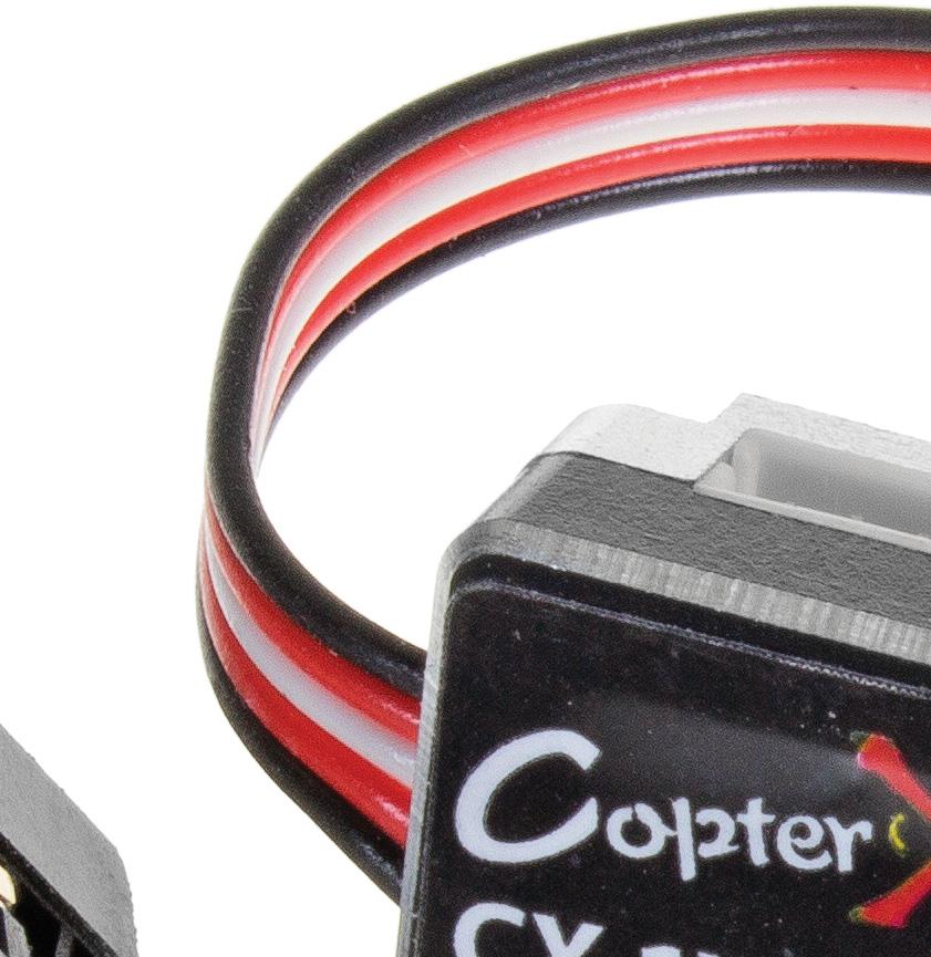
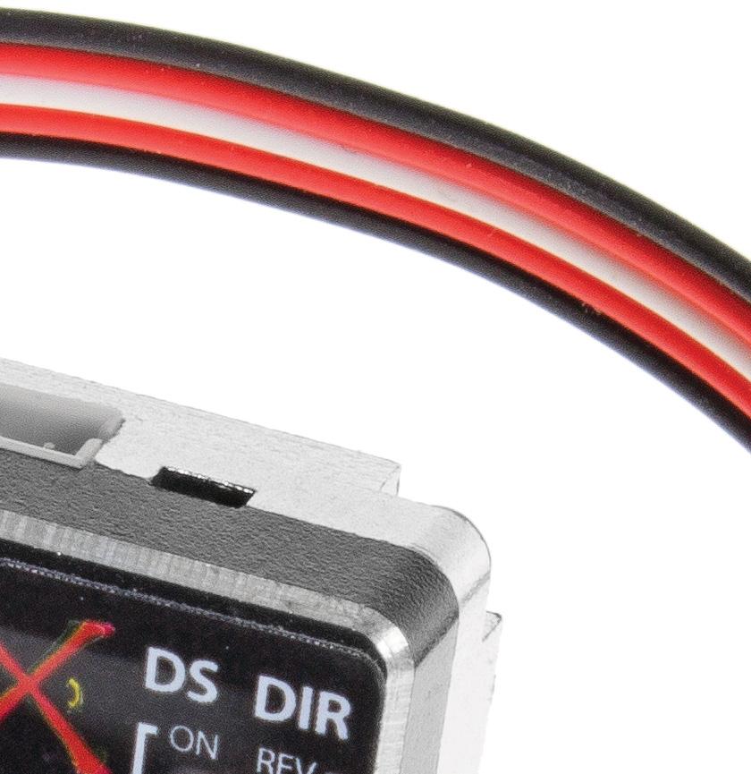
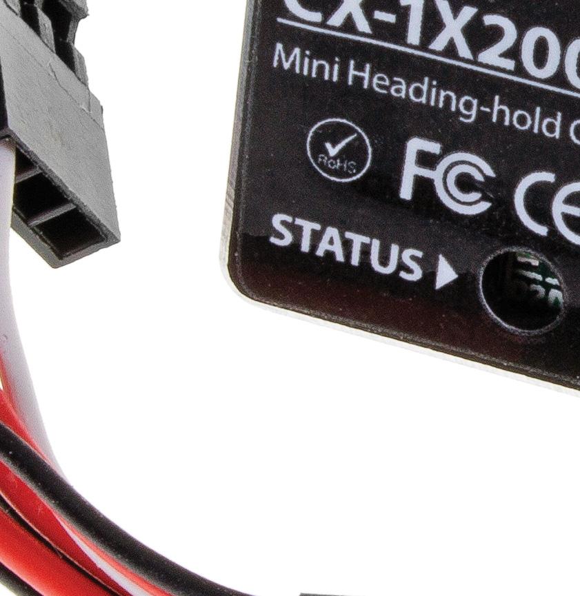
4 4. Functions and Connections Sensitivity Switching Connector DS Mode Switch Gyro Operation Direction Switch Rudder Input Connector Rudder Servo Connector LED Limit Trimmer Sensitivity Switching Connector: Gyro sensitivity switching signal input connector. Connect to the receiver sensitivity switching channel (normally CH5). This connector is also simultaneously used to switch between the AVCS and normal operation modes. Since this connector is a single wire signal line, do not pull it forcefully. Rudder Input Connector: Connects to the receiver rudder channel (CH4) output connector. Rudder Servo Connector: Connects the rudder servo. DS Mode Switch (DS): Digital servo (DS) mode switch. The ON position is the high-speed output mode for digital servo only. When using a normal servo, always set this switch to the OFF position. If it is set to the ON position, the servo will be destroyed. Gyro Operation Direction Switch (DIR): Switches the gyro control direction. It must be switched according to the direction of rotation of the main rotor and the direction of the rudder linkage. If the rudder servo moves in the cancellation direction when the nose of the helicopter moves, the operation direction are good. If you try to fly a model with a clockwise rotation rotor when the gyro operation direction is reversed, the nose will turn to the left and result in a dangerous situation. LED: Indicates the operating status of the CX-1X2000. The display contents are shown in section 5. Limit Trimmer (LIMIT): Sets the maximum travel of the rudder servo. Move the rudder stick to the left and right and adjust the limit trimmer so that the servo operating angle do not strike the linkage. During flight, the servo will not operate beyond this angle and the linkage is protected. When the trimmer is turned clockwise, the servo operating angle increases. 03
5 5. LED Indication Steady Red Steady Blue Steady Red and Blue Blue and Red LED are flashing synchronously Red LED is flashing Gyro is in AVCS mode Gyro is in normal mode Gyro is waiting for receiver's signal Gyro is initializing, keep the gyro steady, rudder stick centered Gyro is in firmware update mode 6. Gyro Mounting The gyro should mount to a steady platform which is perpendicular to the main shaft and far away from the engine and other electric devices. Mount the gyro to the platform by using a soft foam pad, relax the cable of gyro to reduce transmission of vibrations through the cable. Do not allow the gyro case to touch other parts of the helicopter. Mounting on a small electric helicopter: just use a 2-3mm foam pad. 2-3mm Foam Pad Gyro Mounting Platform 90 Mounting on a large or a High vibration helicopters: use a foam pad on each side of the damping shield plate. 2-3mm Foam Pad 2-3mm Foam Pad Gyro Mounting Platform Damping and Shield Plate 90 04
6 7. Installation of Servo Horn and Linkage First of all make sure the mechanical parts of tail rotor install correctly, all parts can move smoothly, and the tail servo install firmly size: 4.5mm 450 / 500 size: mm 600 or larger size: mm Mount control ball to servo horn. We recommend the distance from the ball to center is: 4.5mm (250 size), mm (450, 500 size), mm (600 or larger size). Install the horn to tail servo temporarily, adjust the horn position to make it perpendicular to the linkage, then set the tail pitch to be approximately 8 in the direction that compensates the main rotor torque by adjusting the linkage length. Notice: Don't connect the servo to the gyro until finishing the gyro type configuration. 05
7 8. Transmitter Configuration Power on the transmitter and create a new helicopter model, set the trims and subtrims of all the channels to be zero, and make sure all the mixing functions related to tail turn off. Set up a gain switch in transmitter, which is used to control gyro's working mode (AVCS mode and normal mode). The relationship of the gyro actual gain and the displayed value in some popular transmitters are in the table as follows. We recommend that you can set the gyro actual gain to be about 40%, and then adjust the gain during practical flight. The gain should be raised until the tail begins to oscillate quickly (also called Tail Wag). Once this point has been achieved, reduce the gain a little and do a test0fly again. Check and set the gain for each flight mode. Gyro is in AVCS mode Gyro is in AVCS mode Gyro actual gain Futaba gyro menu 85% 0% 85% Futaba Endpoint 100% 0% 100% JR / Spektrum gyro menu 0% 51% 100% JR / Spektrum Endpoint 104% 1% 108% 9. Parameter Configuration 9.1 Set parameters by using gain switch and rudder stick of transmitter Entering Programming Mode Power on transmitter and dial the switch to AVCS mode, connect the gyro to receiver (before selecting the servo type, disconnect the gyro to servo), move the rudder stick to any maximum extent position and remain it, power on the gyro and the receiver, after the gyro initialization, red and blue LED indicator are off and then they flash alternately again, it shows that gyro has entered Programming mode, now center the rudder stick Change parameter Change the parameters by moving rudder stick right or left in every item of menu Switch to the next menu and save the cahnge Dial gain switch for one time between AVCS and normal mode can save the parameters set in previous menu, and enter into next menu at the same time. 06
8 9.1.4 LED indicator in Programming Mode Red and Blue flash slowly together: switch to a new menu items, the number of flashes is the sequence number. In menu item 1, 2, 7, the number of flashes indicates the parameter of current item. In item 3, 4, 5, 6, fast Red flashes indicate parameter value increasing, fast Blue flash indicates value decreasing. Number of red and blue flash synchronously 1 flash 2 flashes Menu item Servo type Gyro Compensation Direction Description of parameter and condition Red, 1 flash: 1520us 71Hz (analog servo)* Red, 2 flashes: 1520us 250Hz (digital servo) Red, 3 flashes: 1520us 333Hz (digital servo) Red, 4 flashes: 760us 400Hz (digital servo) Red, 5 Flashes: 960us 333Hz (digital servo) NOTICE *Factory default setting Before finishing the servo type selection, don't connect the servo to the gyro Before finishing the item 3 of the menu, don't fix the horn to the servo In Programming mode, the gyro couldn't control the helicopter, don't try to fly in Programming mode The menu is circular, it goes back to the item 1 automatically after item 8 When you want to save the parameters you just setting, you must dial the gain switch between AVCS and normal modes for one time, at the same time it goes to next item of menu The item 6 is an optional function, when it is set, the tail control can be enhanced during the acute pitch changing in 3D flight. For beginners, we recommend setting it to default, if it is set incorrectly, please enter item 8 to reset the parameter to default. If you want to use this function, you need to setup a mixing from pitch channel to a vacant channel in transmitter, and plug the gyro pitch signal wire to this vacant channel of receiver. In the item 7, for beginner we recommend selecting parameter group 1 (F3C mode) After finishing the setup and saving the parameters, you must turn off the power and restart the gyro to fly. 07 Long Red, 1 flash: positive direction* Long Blue, 1 flash: reverse direction 3 flashes Servo trim Servo centered 4 flashes Limit A of servo Servo goes to the limit position of direction A 5 flashes Limit B of servo Servo goes to the limit position of direction B 6 flashes 7 flashes Compensation of pitch to tail Parameter group selection 8 flashes Data reset Servo centered, move the pitch stick up and down to check the value and direction of compensation Red, 1 flash: parameter group 1 is selected (F3C mode)* Red, 2 flashes: parameter group 2 is selected (3D mode) Move rudder stick right and left quickly for several times, until the Blue LED flashes fast, then all the parameter is reset to the factory default settings 9.2 Set parameters by using program box, please check the program box user manual for more details.
9 10. Notices in each flight When turn on the power, the gyro needs several seconds to initialize. During initialization, Red and Blue LED flash synchronously. When initialization is complete, the tail servo will move right and then left to indicate. If the airframe is not immobile or the rudder stick is moved during initialization, the gyro may drift. Remain the airframe immobile and the rudder stick centered, then quickly dial the gain switch between Normal Mode and AVCS Mode for several times, the gyro will initialize again to eliminate drift. Before every flight, verify that the mechanical frame and parts of helicopter is in good condition. 08
10 Copyright 2014 KY MODEL Company Limited.
CX-PB Program Box for CopterX Gyro. Copyright 2011 KY MODEL Company Limited.
 CX-PB001 Program Box for CopterX Gyro INSTRUCTION MANUAL www.copterx.com Copyright 2011 KY MODEL Company Limited. MENU 1. 2. 3. 4. 5. 6. Table of content Introduction Specifications Buttons and Connections
HM4050 AVCS HEADING LOCK GYRO
 INCLUDES HM4050 gyro with connectors Foam adhesive tape Manual HM4050 AVCS HEADING LOCK GYRO FEATURES AVCS (Angular Vector Control System) Small size Lightweight Able to operate in Heading Hold as well
Caution Notes. Features. Specifications. Installation. A3-L 3-axis Gyro User Manual V1.0
 Caution Notes Thank you for choosing our products. If any difficulties are encountered while setting up or operating it, please consult this manual first. For further help, please don t hesitate to contact
GA510 V2.0 AVCS Gyro Instructions Manual
 GA510 V2.0 AVCS Gyro Instructions Manual GA510 is a high-performance AVCS gyro specially designed and optimized for your 3D RC helicopter. Equipped with LCD display, it has the characteristics easy setting,
User Manual Version 1.0
 1 Thank you for purchasing our products. The A3 Pro SE controller is the updated version of A3 Pro. After a fully improvement and optimization of hardware and software, we make it lighter, smaller and
A3 Pro INSTRUCTION MANUAL. Oct 25, 2017 Revision IMPORTANT NOTES
 A3 Pro INSTRUCTION MANUAL Oct 25, 2017 Revision IMPORTANT NOTES 1. Radio controlled (R/C) models are not toys! The propellers rotate at high speed and pose potential risk. They may cause severe injury
INSTRUCTION MANUAL YAW-AXIS STABILIZER FOR MODEL HELICOPTER (RATE GYRO) 1M23N21902
 1M23N21902") INSTRUCTION MANUAL YAW-AXIS STABILIZER FOR MODEL HELICOPTER (RATE GYRO) 1M23N21902 Thank you for purchasing a GY520 AVCS gyro. Before using your new gyro, please read this instruction manual thoroughly
INSTRUCTION MANUAL YAW-AXIS STABILIZER FOR MODEL HELICOPTER (RATE GYRO) 1M23N21902 Thank you for purchasing a GY520 AVCS gyro. Before using your new gyro, please read this instruction manual thoroughly
Rx62H Linear 5 Channel Brick
 Rx62H Linear 5 Channel Brick (DSM 2 Compatible) DOWN Elevator Servo MicronWings Website Features Product: DSM2 receiver with 2 onboard linear servos Channels: 5 Size: 23.0 x 24.0 x 8.0mm Weight: 3.48grams
August/5/2010 FY-20A FLIGHT STABILIZATION SYSTEM TECH INSTALLATION & OPERATION MANUAL
 August/5/2010 FEIYU TECH FY-20A FLIGHT STABILIZATION SYSTEM INSTALLATION & OPERATION MANUAL Dear Pilot, Thank you for purchasing the FY-20A stabilizer from FeiYu Tech. In order to achieve full potential
AVCS GYRO GY502 INSTRUCTION MANUAL YAW-AXIS STABILIZER FOR MODEL HELICOPTER (RATE GYRO)
") AVCS GYRO GY502 INSTRUCTION MANUAL YAW-AXIS STABILIZER FOR MODEL HELICOPTER (RATE GYRO) 2 Thank you for buying a GY502 AVCS gyro. Before using your new gyro, please read this manual thoroughly and use
AVCS GYRO GY502 INSTRUCTION MANUAL YAW-AXIS STABILIZER FOR MODEL HELICOPTER (RATE GYRO) 2 Thank you for buying a GY502 AVCS gyro. Before using your new gyro, please read this manual thoroughly and use
CX-CT6A INSTRUCTION MANUAL. Computer Transmitter. Digital Propotional Radio Control System. 6 channel Radio Control System
 CX-CT6A INSTRUCTION MANUAL 6 channel Radio Control System Digital Propotional Radio Control System www.copterx.com Copyright 2008 KY MODEL Company Limited. MENU Table of content.........................................................................
Fixed Wing Models 55
 Fixed Wing Models 55 Two Snap-Roll programs Automatic switching of control characteristics (access via Set-Up Menu) (access via Set-Up Menu) 56 Fixed Wing Models AUTOMATIC MANOEUVRE The switches to operate
T14MZ Software Update Function Modification Contents (Version: 1.1.0, 1.2.0)
") T14MZ Software Update Function Modification Contents (Version: 1.1.0, 1.2.0) 1M23N14837 Hardware setting This function is for adjusting the sticks, switches and trim characteristics. [System menu] Swash
T14MZ Software Update Function Modification Contents (Version: 1.1.0, 1.2.0) 1M23N14837 Hardware setting This function is for adjusting the sticks, switches and trim characteristics. [System menu] Swash
Smart Bus RRS. Quick Start Guide
 Smart Bus RRS Quick Start Guide Thank you for your purchase of the Advance Radio Smart Bus RRS. In this quick start guide we will show you how to connect your new Smart Bus, General use and Set Up. Please
AVCS GYRO GY501 INSTRUCTION MANUAL YAW-AXIS STABILIZER FOR MODEL HELICOPTER (RATE GYRO) 1M23N04302
 1M23N04302") AVCS GYRO GY501 INSTRUCTION MANUAL 1M23N04302 YAW-AXIS STABILIZER FOR MODEL HELICOPTER (RATE GYRO) AVCS GYRO GY501 INSTRUCTION MANUAL YAW-AXIS STABILIZER FOR MODEL HELICOPTER (RATE GYRO) 4 Thank you for
AVCS GYRO GY501 INSTRUCTION MANUAL 1M23N04302 YAW-AXIS STABILIZER FOR MODEL HELICOPTER (RATE GYRO) AVCS GYRO GY501 INSTRUCTION MANUAL YAW-AXIS STABILIZER FOR MODEL HELICOPTER (RATE GYRO) 4 Thank you for
Jet Central Sequencer Plus
 Jet Central Sequencer Plus Features The Jet Central Sequencer Plus is a multipurpose electronic device, the capabilities of the unit include: Three part sequencer, operating landing gear and two independent
Detrum MSR66A Receiver
 Motion RC User Guide for the Detrum MSR66A Receiver Version 1.0 Contents Review the Receiver s Features... 1 Review the Receiver s Ports and Connection Orientation... 2 Bind the Receiver to a Transmitter
Built-in soft-start feature. Up-Slope and Down-Slope. Power-Up safe start feature. Motor will only start if pulse of 1.5ms is detected.
 Thank You for purchasing our TRI-Mode programmable DC Motor Controller. Our DC Motor Controller is the most flexible controller you will find. It is user-programmable and covers most applications. This
Smart Bus RRS. Quick Start Guide
 Smart Bus RRS Quick Start Guide Thank you for your purchase of the Advance Radio Smart Bus. In this quick start guide we will show you how to connect your new Smart Bus, General use and Set Up. Please
Castle Multi-Rotor ESC Series User Guide
 Castle Multi-Rotor ESC Series User Guide This user guide is applicable to all models of Castle Multi-Rotor ESC. Important Warnings Castle Creations is not responsible for your use of this product or for
Introduction. Overview. Outputs Normal model 4 Delta wing (Elevon) & Flying wing & V-tail 4. Rx states
 & Flying wing & V-tail 4. Rx states") Introduction Thank you for purchasing FrSky S6R/S8R (SxR instead in this manual) multi-function telemetry receiver. Equipped with build-in 3-axis gyroscope and accelerometer, SxR supports various functions.
Introduction Thank you for purchasing FrSky S6R/S8R (SxR instead in this manual) multi-function telemetry receiver. Equipped with build-in 3-axis gyroscope and accelerometer, SxR supports various functions.
A3 SUPER 3 INSTRUCTION MANUAL. For Firmware Version 1.0, Data Version 1.0 Oct 25, 2017 Revision.
 A3 SUPER 3 INSTRUCTION MANUAL For Firmware Version 1.0, Data Version 1.0 Oct 25, 2017 Revision support@hobbyeagle.com 1 CONTENTS IMPORTANT NOTES.....3 1. Introduction......4 2. Setup Procedure Overview...5
Gyroscopic Landing Gear controller and sequencer GS-200. Users Guide.
 Gyroscopic Landing Gear controller and sequencer GS-200 Users Guide. Pol.Ind PPI-7, Parcela K, nave B9, O Porriño, Pontevedra, Spain E-mail: info@electron-retracts.com. web: www.electron-retracts.com Electron
X10+ Channel Expander (V2)
") Xtreme Power Systems X10+ Channel Expander (V2) Installation And Usage Manual Supports: XtremeLink RFU and Nano receivers Futaba SBUS and SBUS2 receivers Spektrum DSM2/DSMX satellite receivers JR DMSS
Xtreme Power Systems X10+ Channel Expander (V2) Installation And Usage Manual Supports: XtremeLink RFU and Nano receivers Futaba SBUS and SBUS2 receivers Spektrum DSM2/DSMX satellite receivers JR DMSS
Autopilot System Installation & Operation Guide. Guilin Feiyu Electronic Technology Co., Ltd
 2011-11-26 FEIYU TECH FY31AP Autopilot System Installation & Operation Guide Guilin Feiyu Electronic Technology Co., Ltd Rm. C407, Innovation Building, Information Industry Park, Chaoyang Road, Qixing
Xtreme Power Systems X24. Integrated Flight Control System. Installation And Usage Manual
 Xtreme Power Systems X24 Integrated Flight Control System Installation And Usage Manual Supports: XtremeLink RFU and Nano receivers Futaba SBUS and SBUS2 receivers Spektrum DSM2/DSMX satellite receivers
To consult the last version available of this document, we recommend you to download it from our web site customer care section.
 Date: June 2009 Document version: V1.0 To consult the last version available of this document, we recommend you to download it from our web site www.alewings.it customer care section. Handbook only for
RADIOLINK T8FB (FHSS) INSTRUCTION MANUAL. 8CH remote control system
 INSTRUCTION MANUAL. 8CH remote control system") RADIOLINK T8FB (FHSS) INSTRUCTION MANUAL 8CH remote control system RADIOLINK ELETRONIC LIMITED Technical updates and additional programming examples available at: www. radiolink.com INTRODUCTION Thank
RADIOLINK T8FB (FHSS) INSTRUCTION MANUAL 8CH remote control system RADIOLINK ELETRONIC LIMITED Technical updates and additional programming examples available at: www. radiolink.com INTRODUCTION Thank
Essential Instructions
 Contents Lemon RX Stabilizer PLUS 7-Channel Receiver Essential Instructions Introducing the Lemon StabPLUS... 2 Functions... 2 Transmitter Requirements... 2 Servos and Power Sources... 3 Setting up the
ARKBIRD-Tiny Product Features:
 ARKBIRD-Tiny Product Features: ARKBIRD System is a high-accuracy autopilot designed for fixed-wing, which has capability of auto-balancing to ease the manipulation while flying. 1. Function all in one
Level Crossing with Barriers and Real Sound LCS6
 Level Crossing with Barriers and Real Sound LCS6 Automatically detects trains using an infra-red sensor mounted below the track bed Operates attached yellow and red leds on level crossing signs (not included)
MTC-2 highlight features: ACU highlight features: Contents. MTC-2 and ACU User Manual V5.1
 MTC-2 can work alone as a twin motor ECS (electronic speed controller) for RC tanks. When the ACU (auxiliary control unit) is connected, it can also control turret rotation, gun elevation, gun firing,
Product Introduction:
 Product Introduction: ARKBIRD-433UHF is a 10-channel module designed for long-distance flight: 1. The advanced code division frequency hopping system (FHSS) produces the only way of frequency hopping sequence
RADIOLINK T8FB (FHSS) INSTRUCTION MANUAL. 8CH remote control system
 INSTRUCTION MANUAL. 8CH remote control system") RADIOLINK T8FB (FHSS) INSTRUCTION MANUAL 8CH remote control system RADIOLINK ELETRONIC LIMITED Technical updates and additional programming examples available at: www. radiolink.com INTRODUCTION Thank
RADIOLINK T8FB (FHSS) INSTRUCTION MANUAL 8CH remote control system RADIOLINK ELETRONIC LIMITED Technical updates and additional programming examples available at: www. radiolink.com INTRODUCTION Thank
Detrum GAVIN-8C Transmitter
 Motion RC Supplemental Guide for the Detrum GAVIN-8C Transmitter Version 1.0 Contents Review the Transmitter s Controls... 1 Review the Home Screen... 2 Power the Transmitter... 3 Calibrate the Transmitter...
System Handling Manual
 Hitec Optic 6 Radio Tutorial For ACRO functions Table of Contents System Modes MODEL SELECTION MODEL NAME MODEL TYPE COPY TRANSMIT SHIFT DIRECTION MODULATION MODE I or MODE II STICK STYLE TIMER SETUP RESET
Programming a Helicopter, model type HE Connection of external control elements to the transmitter board for the helicopter program Helicopter
 Programming a Helicopter, model type HE The initial set-up of the transmitter for helicopter models is achieved using the System Menu, see pages 14 17. The basic set-up depends less on the model itself
Xtreme Power Systems
 Xtreme Power Systems XtremeLink NANO RECEIVER Installation And Usage Manual XtremeLink is a registered trademark of Xtreme Power Systems, LLC. Firmware v 1.9 Manual v 1.9 Revision Date: November 11 th,
Thank you for purchasing this DJI product. Please strictly follow these steps to mount and connect this system on
 NAZA-M LITE User Manual V 1.00 2013.05.28 Revision For Firmware Version V1.00 & Assistant Software Version V1.00 Thank you for purchasing this DJI product. Please strictly follow these steps to mount and
Technical data. General specifications. Measurement range min max. 360
 Model Number Features Very small housing High climatic resistance 12 Bit singleturn Analog output Surge and reverse polarity protection Description This absolute rotary encoder with internal magnetic sampling
RC Camera Control. User Guide v1.3 (RCCC v1.1) 11/7/2012
 11/7/2012") RC Camera Control User Guide v1.3 (RCCC v1.1) 11/7/2012 kristaps_r@rcgroups INTRODUCTION RC Camera Control board (RCCC) is multifunctional control board designed to for aerial photography or First Person
RC Camera Control User Guide v1.3 (RCCC v1.1) 11/7/2012 kristaps_r@rcgroups INTRODUCTION RC Camera Control board (RCCC) is multifunctional control board designed to for aerial photography or First Person
Hyperion 7-channel Stabilized Receiver
 Hyperion 7-channel Stabilized Receiver This is not a Horizon Hobbies DSM2, DSMX product, and is not manufactured or endorsed by Horizon Hobbies LLC. DSM2, and DSMX are registered trademarks of Horizon
FORZA 700 SPEED Supplemental manual
 The FORZA 700 has evolved into a Speed Monster. The finely honed form minimizes air resistance, and the forward tilting rotor head helps transform all available power into speed. Fly beyond limits with
3-Axis gyroscope ~ Airtrix A733-G. User Instructions
 3-Axis gyroscope ~ Airtrix A733-G User Instructions 1. Foreword: The Airtrix series A733-G is a very high performance 3-axis gyro. It is developed for the RC model airplanes. The following players will
ServoDMX OPERATING MANUAL. Check your firmware version. This manual will always refer to the most recent version.
 ServoDMX OPERATING MANUAL Check your firmware version. This manual will always refer to the most recent version. WORK IN PROGRESS DO NOT PRINT We ll be adding to this over the next few days www.frightideas.com
Exercise 3-3. Multiple-Source Jamming Techniques EXERCISE OBJECTIVE
 Exercise 3-3 Multiple-Source Jamming Techniques EXERCISE OBJECTIVE To introduce multiple-source jamming techniques. To differentiate between incoherent multiple-source jamming (cooperative jamming), and
Modified Spektrum DM9 Module for Use with Futaba 8FG, 12FG, 14SG and 18SZ Transmitters INSTRUCTIONS
 Modified Spektrum DM9 Module for Use with Futaba 8FG, 12FG, 14SG and 18SZ Transmitters INSTRUCTIONS Ivan Cankov (ivanc on RCGroups) Modified Spektrum DM9 Module for Use with Futaba 8FG, 12FG, 14SG and
Exercise 6. Range and Angle Tracking Performance (Radar-Dependent Errors) EXERCISE OBJECTIVE
 EXERCISE OBJECTIVE") Exercise 6 Range and Angle Tracking Performance EXERCISE OBJECTIVE When you have completed this exercise, you will be familiar with the radardependent sources of error which limit range and angle tracking
Exercise 6 Range and Angle Tracking Performance EXERCISE OBJECTIVE When you have completed this exercise, you will be familiar with the radardependent sources of error which limit range and angle tracking
MTC-2 highlight features: ACU highlight features: Contents. MTC-2 and ACU User Manual V4.0
 MTC-2 can work alone as a twin motor ECS (electronic speed controller) for RC tanks. When the ACU (auxiliary control unit) is connected, it can also control turret rotation, gun elevation, gun firing,
Other than physical size, the next item that all RC servo specifications indicate is speed and torque.
 RC servos convert electrical commands from the receiver back into movement. A servo simply plugs into a specific receiver channel and is used to move that specific part of the RC model. This movement is
RADIO SETUP INFORMATION
 RADIO SETUP INFORMATION CHOICE Transmitter Setup For The JR DSX11 JR-CCPM plays a critical role in coordinating the simultaneous activating of multiple servos to control the swashplate. Activation of just
Multi-rotor flight stabilization & Autopilot System Installation & Operation Guide. Guilin Feiyu Electronic Technology Co., Ltd
 Rev: 5 th July 2011 FEIYU TECH FY-91Q DREAMCATCHER Multi-rotor flight stabilization & Autopilot System Installation & Operation Guide Guilin Feiyu Electronic Technology Co., Ltd Rm. B305, Innovation Building,
Before you operate the inverter, the parameters that you must first program are the basic parameters.
 . Main parameters Before you operate the inverter, the parameters that you must first program are the basic parameters..1 Searching for changes using the history function () : History function History
MTC-2 highlight features: ACU for Flakpanzer Gepard highlight features: Contents. MTC-2 and ACU User Manual V4.2 (Flakpanzer Gepard Version)
") This manual is written for the ACU for Flakpanzer Gepard. There are some modifications on usage of servo and LED ports. Please also notice that GSU (gun stabilize unit) is not supported. MTC-2 highlight
This manual is written for the ACU for Flakpanzer Gepard. There are some modifications on usage of servo and LED ports. Please also notice that GSU (gun stabilize unit) is not supported. MTC-2 highlight
FY-91Q DREAMCATCHER TECH. Multi-rotor flight stabilization & Autopilot System Installation & Operation Guide
 Rev 6: 7 th July 2011 FEIYU TECH FY-91Q DREAMCATCHER Multi-rotor flight stabilization & Autopilot System Installation & Operation Guide Guilin Feiyu Electronic Technology Co., Ltd Rm. B305, Innovation
Super Sky Surfer 2000 Assembly Instructions
 Super Sky Surfer 2000 Assembly Instructions Note: Plug and Play version of the Sky Surfer comes with fuselage pre-glued and motor/servos installed. If you wish to route antennas or wires through the tail,
Protected multi-channel servo interface. EN User Manual
 Protected multi-channel servo interface User Manual 1. 2. 3. 4. 5. 6. 7. 8. 9. Introduction... 2 1.1 Attributes... 3 Description... 3 2.1 Central Box 200... 3 2.2. Central Box 100... 5 2.3 Magnetic switch
STANDARD FL Description, Connection Diagram Menu Block Diagram Diagram of Adjustments Control Programmes (V-Tail, Delta)...
...") Contents General Instructions mc-16/20 Computer System 3 5 Basic Installation Instructions... 6 9 Connecting External Elements...10 Installing Modules...11 Compatibility...12 Starting Out...12 Multi-Data
Contents General Instructions mc-16/20 Computer System 3 5 Basic Installation Instructions... 6 9 Connecting External Elements...10 Installing Modules...11 Compatibility...12 Starting Out...12 Multi-Data
AUTOMATIC LEVEL CROSSING WITH REAL SOUND FOR 4 GATES/BARRIERS LCS6B4
 AUTOMATIC LEVEL CROSSING WITH REAL SOUND FOR 4 GATES/BARRIERS LCS6B4 Level Crossing Controller for 4 Gates, with Real Sound The LCS6B4 is based on our existing Level Crossing Module, the LCS6B, but able
YGE ProgCard II - Programming Card
 YGE ProgCard II - Programming Card With the programming card, we offer an easy to use programming unit, with which all our ProgCard II capable speed controllers can have their individual functions changed.
Blue Point Engineering
 Blue Point Engineering Instruction I www.bpesolutions.com Pointing the Way to Solutions! Animatronic Wizard - 3 Board (BPE No. WAC-0030) Version 3.0 2009 Controller Page 1 The Wizard 3 Board will record
Exercise 4. Angle Tracking Techniques EXERCISE OBJECTIVE
 Exercise 4 Angle Tracking Techniques EXERCISE OBJECTIVE When you have completed this exercise, you will be familiar with the principles of the following angle tracking techniques: lobe switching, conical
AUTOMATIC LEVEL CROSSING WITH REAL SOUND FOR 2 GATES/BARRIERS LCS6B
 AUTOMATIC LEVEL CROSSING WITH REAL SOUND FOR 2 GATES/BARRIERS LCS6B Fully Flexible Controller with Sound and Servo Motors for Barriers or Gates Automatically detects traction current drawn by scale model
Instruction Manual. B Series Program Mode (BLDC Servos)
") Introduction Instruction Manual Congratulations on the purchase of the HFP-30. The HFP-30 is designed to program all Hitec Digital Programmable Servos (D Series, 5xxx/7xxx, and Brushless) as well as test
Introduction Instruction Manual Congratulations on the purchase of the HFP-30. The HFP-30 is designed to program all Hitec Digital Programmable Servos (D Series, 5xxx/7xxx, and Brushless) as well as test
APPLICATION, EXPORT, AND RECONSTRUCTION
 Thank you for purchasing a Futaba ATTACK 2ER. Before using your ATTACK 2ER, read this manual carefully and use your R/C set safely. After reading this manual, store it in a safe place. APPLICATION, EXPORT,
Table of Contents Introduction/ Table of contents.. System Specifications Transmitter
 Introduction Thank you for purchasing the Hitec Laser digital proportional radio control system. The Laser is loaded with features, easy to use and utilizes the latest in solid-state components for unsurpassed
MegaPoints Controller
 MegaPoints Controller A flexible solution and modular component for controlling model railway points and semaphore signals using inexpensive servos. User guide Revision 10c March 2015 MegaPoints Controllers
DragonLink Advanced Transmitter
 DragonLink Advanced Transmitter A quick introduction - to a new a world of possibilities October 29, 2015 Written by Dennis Frie Contents 1 Disclaimer and notes for early release 3 2 Introduction 4 3 The
PCM/PPM(FM) selectable Radio control system for aircraft
 selectable Radio control system for aircraft") INSTRUCTION MANUAL for Futaba 6EXAP 6-channel, PCM/PPM(FM) selectable Radio control system for aircraft Futaba Corporation Technical updates available at: http://www.futaba-rc.com Entire Contents Copyright
INSTRUCTION MANUAL for Futaba 6EXAP 6-channel, PCM/PPM(FM) selectable Radio control system for aircraft Futaba Corporation Technical updates available at: http://www.futaba-rc.com Entire Contents Copyright
Electronic Speed Controls and RC Motors
 Electronic Speed Controls and RC Motors ESC Power Control Modern electronic speed controls regulate the electric power applied to an electric motor by rapidly switching the power on and off using power
Service Instructions. The Conductor Controls. Conductor DC15-A, Enclosed Unit CH15-A, Open Chasis Unit
 Service Instructions The Conductor Controls Conductor DC15-A, Enclosed Unit CH15-A, Open Chasis Unit Table of Contents General Section Page Safety Instructions.. 4 Introduction 5 Inspection and Long-Term
Thank you for purchasing our product, an ideal radio system for beginners or experienced users alike.
 Thank you for purchasing our product, an ideal radio system for beginners or experienced users alike. Read this manual carefully before operation in order to ensure your safety, and the safety of others
TOP SERVO SIGNAL 5 SERVO SIGNAL 3 SERVO SIGNAL 4 SERVO SIGNAL 6 T B T B T B T B T B SERVO TRIGGER 1 BOTTOM
 Micro Miniatures Servo Controller Channel Location of connections and switches TOP SERVO SIGNAL SERVO SIGNAL 7 SERVO SIGNAL 6 SERVO SIGNAL 5 SERVO SIGNAL SERVO SIGNAL SERVO SIGNAL SERVO SIGNAL SIGNAL COMMON
Operating Handbook For FD PILOT SERIES AUTOPILOTS
 Operating Handbook For FD PILOT SERIES AUTOPILOTS TRUTRAK FLIGHT SYSTEMS 1500 S. Old Missouri Road Springdale, AR 72764 Ph. 479-751-0250 Fax 479-751-3397 Toll Free: 866-TRUTRAK 866-(878-8725) www.trutrakap.com
Operating Instructions
 Operating Instructions Operating Instructions Brief description of the PowerBox 40/24 Champion Petty patent No.: 203 13 420.6 This power supply system, based on the PowerBox Competition, offers a range
HYPERION DSMX COMPATIBLE 8-CHANNEL RECEIVER W/ DIVERSITY & PPM OUTPUT
 * This is not a Horizon Hobbies DSM2, DSMX product, and is not manufactured or endorsed by Horizon Hobbies LLC. DSM2, and DSMX are registered trademarks of Horizon Hobbies LLC. HYPERION DSMX COMPATIBLE
Copyright Graupner/SJ GmbH. Manual. Vector Unit / Vector Unit Extreme 2 channel HoTT 2,4 GHz receiver/servo/speed controller unit No No.
 Copyright Graupner/SJ GmbH EN Manual Vector Unit / Vector Unit Extreme 2 channel HoTT 2,4 GHz receiver/servo/speed controller unit No. 34002 No. 34003 Index Introduction... 4 Service Center... 4 Intended
Deceptive Jamming Using Amplitude-Modulated Signals
 Exercise 3-1 Deceptive Jamming Using Amplitude-Modulated Signals EXERCISE OBJECTIVE To demonstrate the effect of AM noise and repeater inverse gain jamming, two angular deceptive EA used against sequential
T14MZ Software Update (Editor Version:1.6.0, Encoder Version:1.44)
") T14MZ Software Update (Editor Version:1.6.0, Encoder Version:1.44) 1M23N14850 The T14MZ transmitter software version has been updated; the following functions have been added or modified. Reread the instruction
T14MZ Software Update (Editor Version:1.6.0, Encoder Version:1.44) 1M23N14850 The T14MZ transmitter software version has been updated; the following functions have been added or modified. Reread the instruction
New functions and changes summary
 New functions and changes summary A comparison of PitLab & Zbig FPV System versions 2.50 and 2.40 Table of Contents New features...2 OSD and autopilot...2 Navigation modes...2 Routes...2 Takeoff...2 Automatic
07/2015. Instruction Manual
 07/2015 Instruction Manual Dear customer, We are delighted that you have decided to purchase the PowerBox Evolution from our range. We wish you every success with your new PowerBox Evolution, and hope
Digiflight II SERIES AUTOPILOTS
 Operating Handbook For Digiflight II SERIES AUTOPILOTS TRUTRAK FLIGHT SYSTEMS 1500 S. Old Missouri Road Springdale, AR 72764 Ph. 479-751-0250 Fax 479-751-3397 Toll Free: 866-TRUTRAK 866-(878-8725) www.trutrakap.com
ANALOG SERVOS Hitec leads the way with quality reliable servo product to fit any hobby application. Our full line of 32 analog and 16 digital servos a
 ANALOG SERVOS HS-635HB HIGH TORQUE HS-645MG ULTRA TORQUE 133.31 oz.in(9.6kg.cm) 0.20 sec/60 83.32 oz.in(6kg.cm) 0.15 sec/60 1.59 x 0.77 x 1.52in 40.6 x 19.8 x 38.8mm 1.76oz 50g 1.59 x 0.77 x 1.48in 40.6
SLINKE. User s Guide. S.Bus Link for EX Bus. Installation, Operation and Technical Notes
 SLINKE S.Bus Link for EX Bus User s Guide Installation, Operation and Technical Notes V1.2, last revised: 21 Oct 2016 1 General This document provides details on the installation and operation of the "SlinkE"
OVERVIEW. CONTENTS Controller Specifications + Programmable Features Page 2. Wire Connection and Installation Page 3.
 MDRIVE -36A Sensorless Brushless DC Motor Controller User Manual OVERVIEW Unlike other brushless motor controllers, the newly designed MDRIVE Series controllers and ESC-View Software, released for the
Instruction Manual. EVolution
 Instruction Manual EVolution Dear customer, We are delighted that you have decided to purchase the PowerBox Evolution from our range. We wish you every success with your new PowerBox Evolution, and hope
Instructions for Crack Series / Superior RX
 Instructions for Crack Series / Superior RX DSMX and DSM2 Compatibility Superior Rx receivers work with both DSM2 and DSMX versions. DSMX is a development of the earlier DSM2 specification that includes
Precaution of Safety. Before using this product, check that you have all of the following items. If any items are missing, please contact dealer.
 USER MANUAL 1 2 Content Before using this product, check that you have all of the following items. If any items are missing, please contact dealer. Introduction Thank you for purchasing HobbyKing.com HK-7X
UNDERSTANDING RC SERVOS DIGITAL, ANALOG CORELESS, BRUSHLESS
 1 of 12 2/13/10 10:52 AM FIRST STEPS UNDERSTANDING RC SERVOS DIGITAL, ANALOG CORELESS, BRUSHLESS TYPES OF HELIS HOW THEY WORK ACCESSORY INFO As we have briefly discussed, RC servos convert electrical commands
SPECIFICATION, CONTROLS AND ACCESSORIES
 AS440 Automatic Voltage Regulator (AVR) SPECIFICATION, CONTROLS AND ACCESSORIES English Original Instructions A043Y697 (Issue 2) Table of Contents 1. DESCRIPTION... 1 2. SPECIFICATION... 3 3. CONTROLS...
User Guide 3DIGI RELOADED
 RELOADED Version 1.3.1 Dirk Schmidt Index Safety instructions... 3 Technical data... 4 Connections... 5 First start-up... 8 Installation... 8 Preparation of the transmitter... 9 Installation of the software...
RADIO SETTING MANUAL
 RADIO SETTING MANUAL Transmitter Setup For The JR DSX12 JR-CCPM plays a critical role in coordinating the simultaneous activating of multiple servos to contorl the swashplate. Activation of just a single
Digiflight II SERIES AUTOPILOTS
 Operating Handbook For Digiflight II SERIES AUTOPILOTS TRUTRAK FLIGHT SYSTEMS 1500 S. Old Missouri Road Springdale, AR 72764 Ph. 479-751-0250 Fax 479-751-3397 Toll Free: 866-TRUTRAK 866-(878-8725) www.trutrakap.com
Tube Facing Tool.
 www.swagelok.com Tube Facing Tool This manual contains important information for the safe and effective operation of the Swagelok TF72 series tube facing tool. Users should read and understand its contents
EPP Rebel Z 35. White Red w/ Blue Orange w/ Blue Orange w/burgundy Other. Specs. Color - Bottom White Black Checkers Silver Checkers Other Checkers
 EPP Rebel Z 35 Specs AUW ~10.0oz Width 35.28 Length 34.67 Wing Area 1.44 sqft Horz Area 2.35 sqft Vert Area.91 sqft
Advanced User Manual
 Features Advanced User Manual Applications BL-3G Ultra stable 3-Axis Gyro Small size, weight and power USB / PC connection for set up and upgrade MEMS rate sensor - Ultra stable over temperature and time
Acro Naze32 (rev 5) basic guide
 basic guide") Acro Naze32 (rev 5) basic guide by Dlearnt 20 August 2014 1 Introduction I came to this board from a KK (trying a cc3d in between), and wished there was a guide like this to make things a bit easier. This
Acro Naze32 (rev 5) basic guide by Dlearnt 20 August 2014 1 Introduction I came to this board from a KK (trying a cc3d in between), and wished there was a guide like this to make things a bit easier. This
(Build Instructions)
") (Build Instructions) Specifications * Wingspan: 58cm * Length: 50cm * Flying Weight: 59 grams * Channels: 3 (Rudder Elevator Throttle) * Suggested Receiver: 4Ch Micro * Motor: 8mm GearDrive * Prop: GWS
(Build Instructions) Specifications * Wingspan: 58cm * Length: 50cm * Flying Weight: 59 grams * Channels: 3 (Rudder Elevator Throttle) * Suggested Receiver: 4Ch Micro * Motor: 8mm GearDrive * Prop: GWS
SP-6 magnetometer. User manual. Installation and in-flight calibration
 SP-6 magnetometer User manual Installation and in-flight calibration Note: This manual is applicable for SP-6 systems that contain in-flight calibration firmware released by MGL Avionics around the 15
EXMITTER -- Professional Remote Control Products Expert
 EXMITTER -- Professional Remote Control Products Expert WARNING The following terms are used throughout the product literature to indicate various levels of potential harm when operating this product.