Chapter 3 Antennas. Section I. Antenna Selection FM 24-19
|
|
|
- Russell Boyd
- 6 years ago
- Views:
Transcription
1 Chapter 3 Antennas One of the most important considerations when operating a radio is the type of antenna to be used. For good communications with a radio operating in the HF range (2.000 khz to MHz), you must consider the Type of antenna. Operating frequency. Terrain around the radio site. Time of day. Location of and distance between radios. Atmospheric conditions. The operator can sometimes control the first four or five factors. The antenna and frequency are the most important considerations under his control. Both should be selected to suit the distance between the radios and the propagation characteristics. The operator will most likely have two or three different frequencies assigned for the operation or exercise. These will be found in the SOI under the net in which he is operating. Section I. Antenna Selection a. The field environment, tactical situation, and distance between radio sites determine the type of antenna used. If the radio set is used while on the move, the whip antenna supplied with the equipment is normally used. The whip antenna, using the ground wave, is satisfactory for most short-range missions. 3-0
2 b. If the tactical situation permits, a simple half-wave dipole antenna (doublet) or the NVIS antenna is used to extend the range of the radio by using the skip phenomenon. Skip means the radio waves are bounced off the ionosphere and back to earth giving coverage of 300 miles or more. Figure 3-1 shows the ground wave and sky wave using the skip phenomenon. The NVIS can be used at frequencies above 12 MHz but automatic tuning of the radio (AN/PRC-104A and/or AN/GRC-213) may not be possible at all frequencies. c. When using an antenna with directional characteristics, orient the antenna so that it is most sensitive in the direction of the other station(s). Figure 3-2 shows the radiation pattern of the antennas. d. Standard and optional antennas that can be used with IHFRs are listed below. WHIP ANTENNA Omnidirectional (360-degree radiation pattern). Easily and quickly assembled and erected. Lightweight and easy to carry. Limited range (10 miles or less) over land. AS-2259/GR (NVIS) Omnidirectional. Requires large clear area (80 feet square) for proper erection. Long range (0 to 300 miles). 3-1
3 HALF-WAVE DIPOLE DOUBLET QUARTER- WAVE SLANT WIRE Bidirectional (broadside to wire). Good portability. Quickly assembled and erected. Requires two or more vertical supports (trees, poles). Extended range (to 300 miles and beyond). Bidirectional (broadside to wire). Good portability. Quickly assembled and erected. Requires only one vertical support (tree or pole). Range up to 1,000 miles. NOTE: These are a few of the antennas that can be used. Section II. Whip Antenna a. When using a quarter-wave or whip antenna, ground the antenna to increase its effectiveness. Using this characteristic of the ground, an antenna a quarter-wavelength long can be made into the equivalent of a half-wave antenna. If such an antenna is erected vertically and its lower end is grounded, the ground takes the place of the missing quarter-wavelength, and the reflections supply that part of the radiated energy normally supplied by the lower half of an ungrounded half-wave antenna. b. The antenna is grounded by grounding the vehicle itself. Use a ground stake at least 4 feet long, a hammer, and a ground strap. 3-2
4 3-3
5 3-4
6 You may substitute a steel reinforcing rod, a steel fence poet, or a metal water or gas pipe cut to the right length for the ground stake. Ensure paint and rust are removed from such items. Substitutes for the ground strap include battery cables or any heavy gauge wire. Do not use Field Wire WD-1 because it does not provide a suitable ground. Drive the ground stake into the ground until the top of the stake is 2 to 4 inches above the ground. Attach one end of the ground strap to the stake and the other end to the vehicle body. Ensure all paint and rust are removed from connecting point of the vehicle body to allow a good metal-to-metal contact. c. When a whip antenna is mounted on a vehicle, the metal of the vehicle will affect the operation of the antenna. As a result, the direction in which the vehicle is facing may also affect transmission and reception, particularly of distant or weak signals. A vehicle with a whip antenna mounted on its left rear side transmits its strongest signal in a line running diagonally from the antenna through the right front side of the vehicle. Similarly, an antenna mounted on the right rear side of the vehicle radiates its strongest signal in a direction diagonally toward the left front side. In some cases, the best direction can be determined by driving the vehicle in a small circle until the best reception is obtained. Section III. Antenna RC-292 Antenna RC-292 is used to extend the distance range of the old and new generation of FM field radio sets. The antenna consists of one vertical radiating element and three ground plane elements. The lengths of these elements are determined by the operating frequency of the radio set. Refer to the antenna element selection chart at Table 3-1. The antenna is elevated on a 30-foot sectional mast which in turn is held erect by guy ropes and stakes. When the operating frequency is changed, check the antenna element selection chart. If the new frequency requires a change in element length, lower the antenna and add or subtract the required number of elements. 3-5

7 Section IV. Antenna Group OE-254/GRC Description Antenna Group OE-254/GRC is used to extend the range of the old and new generation of FM field radio sets. The antenna consists of three upward and three downward extended radials. These radials remain the same length for all frequencies from 30 to 88 MHz. The antenna is elevated on a 30-foot sectional mast held erect with guy ropes and stakes. NOTE: No change needs to be made in the number of radials when a change of frequency is necessary. 3-6
8 Antenna Group OE-254/GRC Installation CAUTION Use extreme care in driving the stake with the hammer. The space between the ears of the stake is barely enough to clear the hammer. Hitting one of the ears with the hammer will break it. NOTE: Make sure the area for the anchors is firm. If the ground is marshy or sandy, get specific instructions from your supervisor on how to reinforce the anchors. 3-7
9 3-8
10 NOTE: If the antenna is not to be raised to its full height, reduce the number of mast sections. Eliminate the upper mast sections first. The lower and upper adapter assemblies and the insulating extension must be used. 3-9
11 3-10
12 NOTE: Additional weatherproofing of the antenna assembly may be made at this time by wiping the excess silicone compound from the antenna assembly and wrapping each joint with electrical tape. 3-11
13 3-12
14 3-13
15 3-14
16 3-15
17 WARNING 1 When erecting the antenna, allow only team personnel in the erecting area. WARNING 2 Clearly mark all guys with warning flags or signs (supplied by your unit). In an emergency, use strips of white cloth as warning streamers. NOTE: Leave a slight slack in each guy to allow for expansion and contraction of the mast and guys. Check the tension in the morning and during the day. Experience with temperature conditions in the area will determine how tight the guys should be. 3-16
18 WARNING If the weather in your area can cause ice to form on the antenna and guys, add extra guys to support the system. Rope off the area and post it with warning signs, such as beware of falling ice. Keep a sharp aye on the anchors and guys. Check them daily and immediately before and after bad weather. NOTE: For AN/VRC-12 family FM radios with BNC type antenna connectors, use the UG-349B/U adapter on the end of the CG-1886B/U RF cable (Figure 3-12). 3-17
19 3-18

20 Section V. Doublet Antenna Determining Doublet Antenna Length NOTE: This formula does not apply to antennas longer than half-wave. 3-19
21 Section V. Doublet Antenna Determining Doublet Antenna Height The height of the doublet antenna above the ground determines the radiation pattern, or take-off angle. The radiation pattern for a distance of 0 to 250 miles should be straight up. To determine the height of your doublet antenna, use OTF. For daytime uses of 4.8 to 9.7 MHz for a distance of 100 miles, use the formula for a quarterwave. For nighttime uses of the same frequency of 4.8 to 9.7 MHz, use the formula for a tenth of a wave. 3-20
22 Doublet Antenna Orientation WARNING When making adjustmants to an antenna, the transmitter on the radio set must be off. Doublet Antenna Installation Using AB-155A/U Figure 3-15 shows correct installation of a doublet antenna using mast assembly AB-155A/U. Pay particular attention to mast height. For maximum effectiveness, erect a doublet antenna at least a quarter-wavelength off the ground. Forty-foot masts provide adequate height in most instances. 3-21
23 3-22
24 3-23
25 Section VI. NVIS Antenna AS-2259/GR Description a. The NVIS Antenna AS-2259/GR is a lightweight, sloping dipole, omnidirectional antenna. It is designed to be used with an AM radio operating in the HF range of 2 to 30 MHz. It provides high angle radiation (near vertical incidence) to permit short-range sky wave propagation over communications circuits varying from 0 to 300 miles. It can be used with tactical HF radio communications equipment that tunes a 15-foot whip antenna. Examples of such equipment are the AN/GRC-106 and the IHFRs (AN/PRC-104A and AN/GRC-213/193A). Figure 3-16 shows an operational AS- 2259/GR NVIS. b. An adapter MX-10618/GRC-193A is used to interface the vehicle s whip antenna base with the AS-2259/GR. Do not use the adapter MX-9313/GR provided with some of the earlier antenna kits with the AN/PRC-104A or AN/GRC-213/193A. It is used to interface radios with greater output power (AN/MRC83/87). The antenna weighs about 14.7 pounds and can be erected by two men in about 5 minutes. The antenna is polarized horizontally and vertically at the same time, radiating RF energy in all directions at the same time. It consists of eight lightweight mast sections that function as the antenna coax feed line and four radiating elements that also serve as guys supporting the mast. 3-24
26 3-25
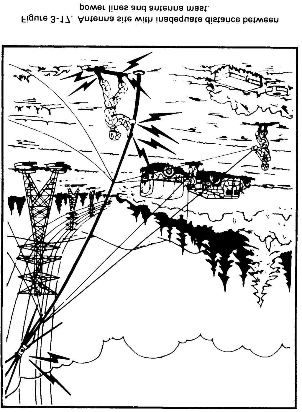
27 NVIS Antenna AS-2259/GR Installation DANGER Antennas must be separated from power lines by a distance equal to twice the height of the antenna. Antenna contact with power lines may cause serious injury or even death to the operator. Be sure transmittal power is off. Contacting the antenna when the transmittal is keyed will cause electrical burns. NOTE: Before assembling mast sections, wipe unpainted surfaces clean of mud or dirt to ensure good electrical contact. 3-26

28 NOTE: Do not use the Adapter MX-9313/GR that may be in earlier models of the AS-2259/GR with any of the IHFR systems. Use the MX with IHFR sets. 3-27
29 3-28
30 3-29
31 3-30
32 3-31
33 Section VII. Field Expedients for Antennas a. Antennas are sometimes broken or damaged resulting in failed or poor communications. If a spare is available, replace the damaged antenna. When there is no spare, fabricate an emergency antenna. For more information on how to repair and fabricate antennas refer to FM The following suggest ways to construct an emergency antenna. (1) The best wire for antennas is copper or aluminum. In an emergency, however, use any wire available. WD-1/TT is suitable for this purpose. (2) The exact length of many antennas is critical. Therefore, the length of the emergency antenna should be the same as the length of the antenna it replaces. (3) Antennas supported by trees can usually survive heavy windstorms if the trunk of a tree or a stout limb is used for support. To keep the antenna taut and to prevent it from breaking or stretching, attach a spring or a strip of old inner tube to one end of the antenna, or pass a rope through a pulley or eye hook, attach the rope to the end of the antenna, and load the rope with a heavy weight to keep the antenna taut. (4) Guys used to hold antenna supports are made of rope or wire. To ensure that wire guys will not affect the operation of the antenna, cut the wire into several short lengths and connect the pieces with insulators. Small pieces of dry wood, bottles, or even suitably shaped stones may be used. b. An improvised antenna may change the performance of a radio set. Use either of the two following expedient methods to determine whether the improvised antenna is operating properly. (1) The distant receiver may be used to test the antenna. If the signal received from a station is strong, the antenna is operating satisfactorily. If the signal is weak, adjust the height and length of the antenna and transmission line to receive the strongest signal at 3-32
34 a given setting of the volume control of the receiver. If your set is equipped with a power or SWR meter, use this device to adjust your antenna. (2) In some radio sets, the transmitter is used to adjust the antenna. First, set the controls of the transmitter in the proper position for normal operation; then, tune the system by adjusting the antenna height, length, and the transmission line length to obtain the best transmission output. c. When a whip antenna is broken into two sections, the portion of the antenna that is broken off can be connected to the portion attached to the base fitting by joining the sections together. When both parts of the broken whip are available and usable, connect the two broken ends together and wrap with wire, ensuring that wrapping is clean and tight. Lash pole or branch to antenna until antenna will stand alone. When the portion of whip that is broken is missing or unusable, add a piece of wire that is nearly the same length as the broken section. Then, lash a pole the length of the antenna securely to the base section of the antenna and tie wire to the top of pole. If possible, solder the connections. d. Emergency repair of wire antennas can be grouped into two categories: repair or replacement of the wire used as an antenna or transmission line; and repair or replacement of the assembly used to support the antenna wires. (1) When one or more wires on an antenna are broken, the antenna can be repaired by reconnecting the broken wires. To do this, lower the antenna to the ground, clean the surface of the wire, and twist the wires together. Whenever possible, solder the connections. (2) If the antenna is damaged beyond repair, substitute another antenna. If antenna sections are not available, WD-1 (field wire) can be used as a substitute. Ensure the length of the wire is the same length as the original antenna and you have a good wire to antenna contact. 3-33


35 e. Building a good field-expedient vertical half-rhombic antenna calls for a good resistor, not a dead BA-30 battery or a C-rat can full of sand and oil. Plan ahead. If you can, lay in a supply of the 600-ohm 2-watt resistors. Since 600-ohms is not a standard resistor value, you have a choice. Get a 620-ohm, 2-watter with NSN , or wire ohm, l-watt resistors in parallel. Get them with NSN Then, follow the directions on how to fabricate antennas. Put the resistor on the end nearest your receiving station. Remember, resistor wattage must beat least half of the radio s output wattage. (See Figure 3-21.) 3-34
36 Section VIII. Grounding Systems WARNING If underground pipes or tanks are used, ensure they do not contain gasoline, oil, or other flammable liquids or gas. 3-35
37 NOTE: Use the wrap method if a terminal screw or a ground clamp is not available. Bind the ground strap to the rod by using strong, flexible bare wire. Wrap about 24 turns of the wire around the strap and the rod, then solder the wire and strap to the rod. If solder is not available, twist the ends of the wire as tight as you can, then tape the connection to keep out moisture. 3-36
APPENDIX D COMMUNICATIONS
 APPENDIX D COMMUNICATIONS LRSU mission success depends on the LRS team s ability to report intelligence gathered. An LRS team that can see everything and report nothing is useless. LRSUs normally use high-frequent
Chapter 5.0 Antennas Section 5.1 Theory & Principles
 Chapter 5.0 Antennas Section 5.1 Theory & Principles G3C11 (B) p.135 Which of the following antenna types will be most effective for skip communications on 40-meters during the day? A. A vertical antenna
User Guide for the Alpha Antenna 6 40 or meter OCF Dipole
 User Guide for the Alpha Antenna 6 40 or 10 80 meter OCF Dipole Manufactured by: Alpha Antenna 1.888.482.3249 Website: http://alphaantenna.com User Guide Version 3.0 March 23, 2018 Page 1 Table of Contents
Table of Contents. MFJ-1778 G5RV Multiband Antenna
 Table of Contents MFJ-1778 G5RV Multiband Antenna Introduction... 1 Theory Of Operation... 1 80 meter band:... 1 40 meter band:... 1 30 meter band:... 2 20 meter band:... 2 17 meter band:... 2 15 meter
Compact Multi-Band Rotatable Dipole Antenna Array
 Compact Multi-Band Rotatable Dipole Antenna Array Dr. John A. Allocca, WB2LUA, www.wb2lua.com, 4/9/12 Introduction Having limited space led to the design of this multi-band antenna array, which has a foot
Technician License. Course
 Technician License Course Technician License Course Chapter 4 Lesson Plan Module - 10 Practical Antennas The Dipole Most basic antenna The Dipole Most basic antenna The Dipole Total length is ½ wavelength
FCC Technician License Course
 FCC Technician License Course 2014-2018 FCC Element 2 Technician Class Question Pool Presented by: Tamiami Amateur Radio Club (TARC) WELCOME To the third of 4, 3-hour classes presented by TARC to prepare
Basic Wire Antennas. Part II: Loops and Verticals
 Basic Wire Antennas Part II: Loops and Verticals A loop antenna is composed of a single loop of wire, greater than a half wavelength long. The loop does not have to be any particular shape. RF power can
The EMCOMM Easytenna
 The EMCOMM Easytenna This document will detail how to build an easy to install multiband dipole type antenna for emergency communications using the NVIS propagation mode. History The NVIS mode is one in
Technician Licensing Class. Antennas
 Technician Licensing Class Antennas Antennas A simple dipole mounted so the conductor is parallel to the Earth's surface is a horizontally polarized antenna. T9A3 Polarization is referenced to the Earth
ANTENNA MATRIX. Antenna Matrix. Purpose. Using the Antenna Selection Proforma
 Purpose The purpose of this Antenna Matrix is to assist you in deciding which antenna from Codan s range best suits your requirements for high frequency (HF) communication over the 2 30 MHz range. The
Emergency Antennas VHF / UHF - FM. HF Voice, CW, or Digital
 1 Emergency Antennas VHF / UHF - FM HF Voice, CW, or Digital 2 Antennas for VHF Quarter Wave Vertical Half Wave Vertical Vertical Dipole J-Pole 3 Design Parameters Primarily line of sight Mounted on trunk
Portable or Emergency VHF Antennas Paul R. Jorgenson KE7HR
 For emergency or public service events it is often necessary to have more antenna than the rubber duck on your handheld VHF radio. Nearly ANY external antenna will provide more coverage for your handheld
Emergency Antennas. Presented by Ham Hilliard W4GMM
 Emergency Antennas Presented by Ham Hilliard W4GMM Dipole antenna Vertical antenna Random wire antenna Dipole antenna The half wave dipole antenna consists of a conductive wire or rod that is half the
4 Antennas as an essential part of any radio station
 4 Antennas as an essential part of any radio station 4.1 Choosing an antenna Communicators quickly learn two antenna truths: Any antenna is better than no antenna. Time, effort and money invested in the
SB-400 HF Antennas SB-400
 SB-400 HF Antennas SB-400 The SB-400 Series of antennas are man-portable and rapid-deployable for HF communications. The HF ANTENNA communication mode is for paths from 10 to 400 km. This communication
PAC-12 Kit Contents. Tools Needed Soldering iron Phillips screwdriver Wire stripper Wrenches, 7/16 and 1/2 Terminal crimp tool Pliers Solder
 PAC-2 Kit Contents Part Quantity Screws: 8/32 x 3/8 Screws: 8-32 x 5/6 Screw: 8-32 x /4 #8 internal tooth washers #8 solder lug ring terminals Bolt: Aluminum, /4-20 x.5 /4 internal tooth washer Nut: Aluminum
Installation Instructions Hustler 6-BTV Trap Vertical
 Installation Instructions Hustler 6-BTV Trap Vertical ASSEMBLY 1. Check the package contents against the parts list on page 2. 2. WARNING. Installation of this product near power lines is dangerous. For
Installation Instructions Hustler 6-BTV Trap Vertical
 Installation Instructions Hustler 6-BTV Trap Vertical ASSEMBLY 1. Check the package contents against the parts list on page 2. 2. WARNING. Installation of this product near power lines is dangerous. For
ALWAYS ATTACH THE SAFETY ROPE TO A STABLE SUPPORT BEFORE ATTEMPTING TO ATTACH THE UNIVERSAL MOUNT TO A WINDOW FRAME OR RAIL.
 MFJ-1623 Introduction The MFJ-1623 was designed to provide portable or permanent HF communications on 30 through 10 meters and VHF on 6 meters. The universal mount design allows the user to install the
Antennas and Propagation Chapters T4, G7, G8 Antenna Fundamentals, More Antenna Types, Feed lines and Measurements, Propagation
 Antennas and Propagation Chapters T4, G7, G8 Antenna Fundamentals, More Antenna Types, Feed lines and Measurements, Propagation =============================================================== Antenna Fundamentals
Technician License Course Chapter 4. Lesson Plan Module 10 Practical Antennas
 Technician License Course Chapter 4 Lesson Plan Module 10 Practical Antennas The Dipole Most basic antenna Total length is ½ wavelength (½ λ) Usual construction: Two equal halves of wire, rod, or tubing
4/29/2012. General Class Element 3 Course Presentation. Ant Antennas as. Subelement G9. 4 Exam Questions, 4 Groups
 General Class Element 3 Course Presentation ti ELEMENT 3 SUB ELEMENTS General Licensing Class Subelement G9 Antennas and Feedlines 4 Exam Questions, 4 Groups G1 Commission s Rules G2 Operating Procedures
Cisco Aironet Omnidirectional Mast Mount Antenna (AIR-ANT2506)
") Cisco Aironet Omnidirectional Mast Mount Antenna (AIR-ANT2506) This document outlines the specifications, describes the omnidirectional mast mount antenna, and provides instructions for mounting it. Designed
Cisco Aironet Omnidirectional Mast Mount Antenna (AIR-ANT2506) This document outlines the specifications, describes the omnidirectional mast mount antenna, and provides instructions for mounting it. Designed
INSTRUCTION MANUAL. Model 18AVQII Five Band Vertical Antenna 10, 15, 20, 40, 80 Meter
 Model 18AVQII Five Band Vertical Antenna 10, 15, 20, 40, 80 Meter 308 Industrial Park Road Starkville, MS 39759 (662) 323-9538 Fax: (662) 323-5803 INSTRUCTION MANUAL General Description The Hy-Gain 18AVQII
Ten-Tec Model 3402 and 3403 Broadband Antennas Installation and Operation Manual PN 74393
 1. Introduction Ten-Tec Model 3402 and 3403 Broadband Antennas Installation and Operation Manual PN 74393 The Ten-Tec Model 3402 Broadband Terminated Vee Beam Antenna offers continuous coverage between
INSTRUCTION MANUAL HF AUTOMATIC TUNING ANTENNA AH-740. * The stand in the photo is not supplied with the tuning antenna.
 INSTRUCTION MANUAL HF AUTOMATIC TUNING ANTENNA AH-740 * The stand in the photo is not supplied with the tuning antenna. FOREWORD Thank you for purchasing the AH-740 hf au to m at i c tuning antenna. The
INSTRUCTION MANUAL. Model 18AVQII Five Band Vertical Antenna 10, 15, 20, 40, 80 Meter. General Description. Theory of Operation
 Model 18AVQII Five Band Vertical Antenna 10, 15, 20, 40, 80 Meter 308 Industrial Park Road Starkville, MS 39759 (662) 323-9538 Fax: (662) 323-5803 INSTRUCTION MANUAL General Description The Hy-Gain 18AVQII
Chapter 6 Antenna Basics. Dipoles, Ground-planes, and Wires Directional Antennas Feed Lines
 Chapter 6 Antenna Basics Dipoles, Ground-planes, and Wires Directional Antennas Feed Lines Some General Rules Bigger is better. (Most of the time) Higher is better. (Most of the time) Lower SWR is better.
Antenna Design for FM-02
 Antenna Design for FM-02 I recently received my FM-02 FM transmitter which I purchased from WLC. I researched the forum on what antennas where being used by the DIY community and found a nice write-up
User Guide for the Alpha FMJ (Full Metal Jacket) Portable HF Antenna
 Portable HF Antenna") User Guide for the Alpha FMJ (Full Metal Jacket) Portable HF Antenna Manufactured by: Alpha Antenna 1.888.482.3249 Website: http://alphaantenna.com User Guide Version 3.1 October 18, 2018 Page 1 Table
User Guide for the Alpha FMJ (Full Metal Jacket) Portable HF Antenna Manufactured by: Alpha Antenna 1.888.482.3249 Website: http://alphaantenna.com User Guide Version 3.1 October 18, 2018 Page 1 Table
BARRETT. 911 Automatic antenna tuner Installation instructions. General. Specifications COMMUNICATIONS
 BARRETT COMMUNICATIONS 0 0 0 Automatic antenna tuner Installation instructions Diameter = mm Connection 0 BARRETT AUTOMATIC ANTENNA TUNER General 0 Control Cable Gland Ground Connection The Barrett Automatic
Technician Licensing Class T9
 Technician Licensing Class T9 Amateur Radio Course Monroe EMS Building Monroe, Utah January 11/18, 2014 January 22, 2014 Testing Session Valid dates: July 1, 2010 June 30, 2014 Amateur Radio Technician
Introduction LOADING COIL COUNTERPOISE ATTACHMENT ANTENNA ATTACHMENT. Figure 1: MFJ-1625 Window/Balcony Mount Antenna
 Introduction MFJ-1625 The MFJ-1625 is a 200 Watt antenna tuner that was designed to provide portable or permanent HF communications on 80 through 10 meters and VHF on 6 meters. The universal mount design
White Paper Security Cameras, CATV, GPS and Satellite Protection
 White Paper Security Cameras, CATV, GPS and Satellite Protection 1485-042 White Paper Security Cameras, CATV, GPS and Satellite Protection Security Cameras, CATV, GPS & Satellite Protection Outdoor Closed
M2 Antenna Systems, Inc. Model No: 2M HO LOOP
 M2 Antenna Systems, Inc. Model No: 2M HO LOOP SPECIFICATIONS: Model... 2M HO LOOP Frequency Range... 144 To 144.5 MHz Gain, Typical @ 10 ft.... 4 dbd @ 10 deg. Gain, 2 STK @ 82 & 132... 8 dbd @ 9 deg.
87.5 TO MHz BAND II 2 WAY 4.8dBi STACKED DIPOLE ANTENNA
 87.5 TO 108.0 MHz BAND II 2 WAY 4.8dBi STACKED DIPOLE ANTENNA 1. INTRODUCTION 3 1.1. GENERAL INFORMATION 3 1.2. UNPACKING AND CHECKING 3 1.3. WARRANTY 3 1.4. USER SAFETY RESPONSIBILITY 4 1.5. INSTALLATION
BUILD A HIGH PERFORMANCE TWO ELEMENT TRI-BAND CUBICAL QUAD. By Bob Rosier K4OCE INTRODUCTION THEORY AND GENERAL INFORMATION
 BUILD A HIGH PERFORMANCE TWO ELEMENT TRI-BAND CUBICAL QUAD INTRODUCTION By Bob Rosier K4OCE Lots of DX can be worked with a dipole at the QRP level, however, a beam will obviously give you additional gain
User Guide. For. Alpha Antenna ProMaster
 User Guide For Alpha Antenna ProMaster Manufactured by: Alpha Antenna 1.888.482.3249 Website: http://alphaantenna.com User Guide Version 2.5 October 2, 2016 Page 1 Introduction Thank you for your support
Aerial-51 Model 404-UL
 Page1 1 Aerial-51 Model 404-UL 7-Band, 200 w High-Performance Asymmetrical Inverted-V For Portable & Fixed-Station Installations 40/20/15/10/6m (plus 17/12m with antenna tuner) Instruction Manual Page2
MQ-24SR Miniature Four band Hybrid Quad Antenna
 MQ-24SR Miniature Four band Hybrid Quad Antenna Most antennas are large heavy structures requiring heavy duty structures, rotors and lots of extra muscle during installation and lots of extra dollars before
Model S9v. 43 Multiband Vertical Antenna Installation Guide
 Model S9v 43 Multiband Vertical Antenna Installation Guide. WARNING: INSTALLATION OF THIS PRODUCT NEAR POWERLINES IS DANGEROUS. FOR YOUR SAFETY, FOLLOW THE INSTALLATION DIRECTIONS. INTRODUCTION Thank you
FM BROADCASTING BAND II 4 WAY dbi STACKED CIRCULAR ANTENNA
 FM BROADCASTING BAND II 4 WAY + 5.8 dbi STACKED CIRCULAR ANTENNA Please read this manual carefully. To avoid harmful interference to other users of the electromagnetic spectrum, do not power up the antenna
4/25/2012. Supplement T9. 2 Exam Questions, 2 Groups. Amateur Radio Technician Class T9A: T9A: T9A: T9A:
 Amateur Radio Technician Class Element 2 Course Presentation ti ELEMENT 2 SUB-ELEMENTS Technician Licensing Class Supplement T9 Antennas, Feedlines 2 Exam Questions, 2 Groups T1 - FCC Rules, descriptions
Observations Regarding Selection and Installation of Masthead VHF whip antennas:
 VHF AIS masthead antenna and coax installation, selection, and test. Stan Honey and Dan Jowett 28 August 2018 Observations Regarding Selection and Installation of Masthead VHF whip antennas: Whip Antennas
High Performance 40 Meters Vertical Without Radials
 High Performance 40 Meters Vertical Without Radials This shortened easy-to-build vertical, with no-radials, is made from surplus military camouflage poles. It has gain and wave angle comparable to a full-sized
MFJ Manual Loop Tuner Considerations
 Pagina 1 0 items Proceed to Secure Checkout All Categories Accessories Analyzers Products Tuners Morse Code / CW Power Supplies Product Search Search! List All Products Site Menu Customer Account Order
Nick Garner N3WG and George Zafiropoulos KJ6VU
 Nick Garner N3WG and George Zafiropoulos KJ6VU Introduction Over the last few years, there has been a significant increase in the number of radio amateurs interested in portable operating. This is due
Site Surveying and Antenna Mounting
 Site Surveying and Antenna Mounting Abdus Salam ICTP, February 2005 School on Digital Radio Communications for Research and Training in Developing Countries Ermanno Pietrosemoli Latin American Networking
Hardware Store 40m Magnetic Loop Antenna for Regional and EMCOM Use. Richard Bono NO5V. QST Antenna Design Competition 80 through 10 meter entry
 Hardware Store 40m Magnetic Loop Antenna for Regional and EMCOM Use Richard Bono NO5V QST Antenna Design Competition 80 through 10 meter entry Overview: This describes a field deployable magnetic loop
Least understood topics by most HAMs RF Safety Ground Antennas Matching & Feed Lines
 Least understood topics by most HAMs RF Safety Ground Antennas Matching & Feed Lines Remember this question from the General License Exam? G0A03 (D) How can you determine that your station complies with
Alpha Delta Communications, Inc. Model DX-OCF Off-Center-Fed 7 Band Antenna
 Alpha Delta Communications, Inc. Model DX-OCF Off-Center-Fed 7 Band Antenna 75/80, 40, 20, 17, 12, 10, and 6 meters (50.0-51.0 MHz) NO TUNER REQUIRED! Installation Instructions One leg is 45 ft., the other
User Guide. For. Alpha Antenna ProMaster Sr. Civilian Military Systems
 User Guide For Alpha Antenna ProMaster Sr Civilian Military Systems Manufactured by: Alpha Antenna 1.888.482.3249 Website: http://alphaantenna.com User Guide Version 2.5 March 17, 2017 Page 1 Introduction
Type 2701 and 2702 Series GRANGER Horizontally Polarized, Log-Periodic HF Antennas
 Type 2701 and 2702 Series GRANGER Horizontally Polarized, Log-Periodic HF Antennas 2-30 MHz Frequency Range Up to kw Average, kw Peak Power Rating Horizontal Polarization 2.0:1 Maximum VSWR Short-to-Medium-Range
Pacific Antenna 20 and 40M Lightweight Dipole Kit
 Pacific Antenna 20 and 40M Lightweight Dipole Kit Diagram showing configuration and approximate lengths 8 3 16 9 16 9 8 3 Description The Pacific Antenna lightweight dual band, trap dipole kit provides
22'W x 13'H Peak Style Shelter Frame Assembly Instructions
 22'W x 13'H Peak Style Shelter Frame Assembly Instructions Recommended Tools Please read instructions COMPLETELY before assembly. This shelter MUST be securely anchored. THIS IS A TEMPORARY STRUCTURE AND
6M HALO VERSON II + OPTIONAL 2M GROUND PLANE
 The halo is an omnidirectional, horizontally polarized antenna with about the same gain as a dipole but without the low elevation nulls off the ends (+5.5 to +3.5dBi variation for the Halo vs. +7.9 to
AV-12AVQ Triband HF Vertical 10, 15, 20-Meter INSTRUCTION MANUAL
 308 Industrial Park Starkville, MS 39759 USA Ph: (662) 323-9538 FAX: (662) 323-6551 AV-12AVQ Triband HF Vertical 10, 15, 20-Meter INSTRUCTION MANUAL General Description This vertical antenna is designed
ANTENNA THEORY WAVE PROPAGATION HF ANTENNAS
 ANTENNA THEORY WAVE PROPAGATION & HF ANTENNAS FREQUENCY SPECTRUM INFORMATION Frequency range American designator below 300 Hz..ELF (extremely Low Frequency) 300-3000 Hz..ILF (Intermediate Low Frequency)
Tarheel Antennas, Inc.
 Tarheel Antennas, Inc. Instruction Manual for the Model 100A-HP Continuous Coverage HF Antenna PROUDLY MADE IN THE UNITED STATES OF AMERICA 18511 CR 304 St. Joseph, MO 64505 816-671-9409 / 816-364-2619
Cisco Aironet 2.4-GHz/5-GHz 8-dBi Directional Antenna (AIR-ANT2588P3M-N)
") Cisco Aironet.4-GHz/5-GHz 8-dBi Directional Antenna (AIR-ANT588P3M-N) This document outlines the specifications for the Cisco Aironet AIR-ANT588P3M-N.4/5-GHz 8-dBi 3-Port Directional Antenna with N-connectors
Cisco Aironet.4-GHz/5-GHz 8-dBi Directional Antenna (AIR-ANT588P3M-N) This document outlines the specifications for the Cisco Aironet AIR-ANT588P3M-N.4/5-GHz 8-dBi 3-Port Directional Antenna with N-connectors
Tactical Dipole (CHA TD) Operator s Manual
 Operator s Manual") Tactical Dipole (CHA TD) Operator s Manual California - USA WWW.CHAMELEONANTENNA.COM VERSATILE DEPENDABLE STEALTH BUILT TO LAST Table of Contents Introduction... 3 HF Propagation... 3 Parts of the Antenna...
Tactical Dipole (CHA TD) Operator s Manual California - USA WWW.CHAMELEONANTENNA.COM VERSATILE DEPENDABLE STEALTH BUILT TO LAST Table of Contents Introduction... 3 HF Propagation... 3 Parts of the Antenna...
Multiband Vertical Antenna Project 2004 by Harold Melton, KV5R
 2004 by Harold Melton, KV5R Page 1 of 5 Printed 1/14/2004 05:02:00 PM Multiband Vertical Antenna Project 2004 by Harold Melton, KV5R Purpose If you could only have two antennas, what would they be? It
User Guide. For. Alpha Antenna. Model: Multiband (Black Match)
") User Guide For Alpha Antenna Model: Multiband (Black Match) Manufactured by: Alpha Antenna 1.888.482.3249 Website: http://alphaantenna.com Available from the: AmateurRadioStore.com Website: https://amateurradiostore.com
User Guide For Alpha Antenna Model: Multiband (Black Match) Manufactured by: Alpha Antenna 1.888.482.3249 Website: http://alphaantenna.com Available from the: AmateurRadioStore.com Website: https://amateurradiostore.com
Mast and Antennas for Field Day & Emergencies
 Mast and Antennas for Field Day & Emergencies John A. Allocca, WB2LUA, July 2005 This is a 27 feet 1.5 diameter portable guyed mast with a 28 feet diameter footprint. It breaks down into four 6 feet sections
Tarheel Antennas, Inc.
 Tarheel Antennas, Inc. Instruction Manual for the Model 40A-HP Continuous Coverage HF Antenna PROUDLY MADE IN THE UNITED STATES OF AMERICA 18511 CR 304 St. Joseph, MO 64505 816-671-9409 / 816-364-2619
INSTRUCTION MANUAL ORDER NO. V3R MODEL V3R. Collinear Gain Vertical for MHz
 ORDER NO. V3R MODEL V3R Collinear Gain Vertical for 216-225 MHz INSTRUCTION MANUAL General Description The new Hy-Gain V3R VHF antenna is a collinear 5/8-wave omnidirectional vertical antenna for the 216-225
Newspaper cartoon from the early 60 s
 Newspaper cartoon from the early 60 s NVIS for Emergency Communications Ross Mazzola Monroe County (NY) ARES Why NVIS? Damage to Infrastructure Inoperative Towers & Repeater Sites Loss of Backup Power
MODEL DB-1015A 10- and 15-Meter Duo-Band Antenna Order No. 330
 MODEL DB-1015A 10- and 15-Meter Duo-Band Antenna Order No. 330 HY-GAIN ELECTRONICS CORPORATION 8601 Northeast Highway 6 Lincoln, Nebraska 68505 Telephone 464-9151 Area Code 402 TABLE OF CONTENTS page SECTION
Amateur Radio License. Propagation and Antennas
 Amateur Radio License Propagation and Antennas Todays Topics Propagation Antennas Propagation Modes Ground wave Low HF and below, ground acts as waveguide Line-of-Sight (LOS) VHF and above, radio waves
DESCRIPTION & FEATURES
 INTRODUCTION Introducing the Tilt-N-Raise antenna mounting mount, a safer way to mount portable communications antenna and supports. The Tilt-N-Raise is a safe and effective way to put up a support mast
Users Manual. 200W HF/50MHz Band Auto Antenna Tuner. Model HC-200AT
 Users Manual 200W HF/50MHz Band Auto Antenna Tuner Model HC-200AT Caution 1. Never remove or open the tuner cover while transmitting. When there is RF in the circuits of the tuner, there will be high voltage
Ameritron RCS-10 INTRODUCTION
 Ameritron RCS-10 INTRODUCTION The RCS-10 is a versatile antenna switch designed for 50-ohm systems. It handles high power, and sealed relays offer excellent life and connection reliability. It requires
A 6-Meter Quad-Turnstile
 By L. B. Cebik, W4RNL A 6-Meter Quad-Turnstile Looking for improved omnidirectional, horizontally polarized performance? This 6-meter turnstile uses the quad loop as a foundation. Turnstile Principles
Tactical Dipole (CHA TD) Operator s Manual
 Operator s Manual") Tactical Dipole (CHA TD) Operator s Manual California - USA WWW.CHAMELEONANTENNA.COM VERSATILE DEPENDABLE STEALTH BUILT TO LAST Table of Contents Introduction... 3 HF Propagation... 3 Parts of the Antenna...
Tactical Dipole (CHA TD) Operator s Manual California - USA WWW.CHAMELEONANTENNA.COM VERSATILE DEPENDABLE STEALTH BUILT TO LAST Table of Contents Introduction... 3 HF Propagation... 3 Parts of the Antenna...
Last year I described several Low Band RX antennas that would enable you to hear DX stations on 160, 80 and 40M. This will show you how to build
 Last year I described several Low Band RX antennas that would enable you to hear DX stations on 160, 80 and 40M. This will show you how to build transmit antennas that will help you break the pileups!
BUILD A SHORTWAVE ANTENNA "The Search For The Perfect Shortwave Antenna" by N4UJW Webmaster Hamuniverse.com
 BUILD A SHORTWAVE ANTENNA "The Search For The Perfect Shortwave Antenna" by N4UJW Webmaster Hamuniverse.com THE MULTIBAND LONG WIRE SHORTWAVE ANTENNA A Much Better But More Complicated Antenna This antenna
Antennas! November 2018
 1 Antennas! November 2018 Agenda 6PM Show and Tell plus Demos in the Park 7PM Welcome: new members and visitors Announcements Antenna Overview Alpha Loop Antenna N6IET Vertical Colinear WB6MMQ Whip Dipole
TW4040. The Adventurer Monobander INSTRUCTION MANUAL. TransWorld Antennas
 TW4040 The Adventurer Monobander TransWorld Antennas INSTRUCTION MANUAL Contents 1 Limited Warranty 3 2 Important Safety Information 4 3 Specifications 3.1 Mechanical 4 3.2 Electrical 4 3.3 VSWR Performance
Pacific Antenna 20 and 40M Lightweight Dipole Kit
 Pacific Antenna 20 and 40M Lightweight Dipole Kit Diagram showing configuration and approximate lengths 8 6 16 9 16 9 8 6 Description The Pacific Antenna lightweight dual band, trap dipole kit provides
Tarheel Antennas, Inc.
 Tarheel Antennas, Inc. Instruction Manual for the Model 300A Continuous Coverage HF Antenna PROUDLY MADE IN THE UNITED STATES OF AMERICA 18511 CR 304 St. Joseph, MO 64505 816-671-9409 / 816-364-2619 Fax
A Guide to building your own Portable Station Incorporating a ¼ Wave Vertical Antenna and a Ground Tuning Unit or GTU
 A Guide to building your own Portable Station Incorporating a ¼ Wave Vertical Antenna and a Ground Tuning Unit or GTU Date: 06.02.2016 By: Alex Ball VK2HAS Credits: I was introduced to the GTU by Dave
User Guide for the Alpha Loop Sr Antenna
 User Guide for the Alpha Loop Sr Antenna Manufactured by: Alpha Antenna 1.888.482.3249 Website: http://alphaantenna.com Available from: Amateur Radio Store Website: https://amateurradiostore.com User Guide
12'W x 10'H RoundTop Frame Assembly Please read and understand instructions completely before assembly.
 12'W x 10'H RoundTop Frame Assembly Please read and understand instructions completely before assembly. Layout out frame parts as shown and match up items with quantity to make sure no parts are missing.
Model VB-23FM 2-Meter 3-Element Beam
 308 Industrial Park Road Starkville, MS 39759 USA Ph: (662) 323-9538 FAX: (662) Model VB-23FM 2-Meter 3-Element Beam [ INSTRUCTION MANUAL Figure 1 Overall View and Boom Detail GENERAL DESCRIPTION This
TENNADYNE TD-160HP800
 TENNADYNE Aluminum with a PhD ASSEMBLY INSTRUCTIONS TD-160HP800 SPECIFICATIONS: Impedance: 50 Ohm nominal Bandwidth :1.8-30 MHz Length : 160 ft. Power : 8 KW Impulse 2400 W PEP SSB 800 W AM/FM/RTTY Connector
Grounding (Counterpoise)
") CHAPTER 8 Grounding (Counterpoise) Good grounding or counterpoise techniques are absolutely necessary for maximum single sideband range. Half your antenna is your radio frequency ground, so don't skimp
CHAPTER 8 Grounding (Counterpoise) Good grounding or counterpoise techniques are absolutely necessary for maximum single sideband range. Half your antenna is your radio frequency ground, so don't skimp
The J-Pole Antenna. Gary Wescom
 The J-Pole Antenna Gary Wescom - 2018 Much has been written about the J-Pole antenna. A simple Google search will net days worth of reading material on the subject. That would tend to indicate this paper
INSTALLATION INSTRUCTIONS
 INSTALLATION INSTRUCTIONS INSTALLATION INSTRUCTIONS THESE INSTRUCTIONS COVER THE INSTALLATION OF THE FOLLOWING REAR DOORS WITH OUTSIDE CABLES AND MAXIMUM SECURITY LOCK: 3/4" DryFreight 1-1/8" PolarGuard
THE ROLL OF AMATEUR RADIO TRAFFIC HANDLERS DURING AN EMERGENCY
 THE ROLL OF AMATEUR RADIO TRAFFIC HANDLERS DURING AN EMERGENCY If the worst possible event were to take place, i.e. a magnitude 8 or greater earthquake we would lose all of the following. Hydro Landlines
Antenna Glossary. BEAMWIDTH The angle of signal coverage provided by an antenna. Beamwidth usually decreases as antenna gain increases.
 ADAPTIVE (SMART) ANTENNA An antenna system having circuit elements associated with its radiating elements such that one or more of the antenna properties are controlled by the received signal. ANTENNA
SPORTCRAFT ANTENNAS. INSTALLATION INSTRUCTIONS for FLUSH WINGTIP COM ANTENNAS
 01A SPORTCRAFT ANTENNAS INSTALLATION INSTRUCTIONS for FLUSH WINGTIP COM ANTENNAS 1.0 INTRODUCTION. 1.1 GENERAL. These antennas have been designed by Bob Archer of Torrance, California utilizing concepts
MFJ-949E. tuner antenowy skrzynka antenowa. Instrukcja obsługi. importer:
 Instrukcja obsługi MFJ-949E tuner antenowy skrzynka antenowa importer: PRO-FIT Centrum Radiokomunikacji InRadio ul. Puszkina 80 92-516 Łódź tel: 42 649 28 28 e-mail: biuro@inradio.pl www.inradio.pl MFJ-949E
ALWAYS ATTACH THE SAFETY ROPE TO A STABLE SUPPORT BEFORE ATTEMPTING TO ATTACH THE UNIVERSAL MOUNT TO A WINDOW FRAME OR RAIL.
 MFJ-1622 Introduction The MFJ-1622 Antenna was designed to provide portable or permanent HF communications on 40 through 10 meters and VHF on 6 and 2 meters. The universal mount design allows the user
AD5X. Low Cost HF Antennas & Accessories. Phil Salas - AD5X Phil Salas AD5X. Richardson, Texas
 Low Cost HF Antennas & Accessories Phil Salas - AD5X ad5x@arrl.net PVC Tubing PVC pipe: Considers the inside diameter (ID) of the pipe. For PVC pipe (schedule 40): 1/2" PVC pipe has an ID of 0.6" and an
Directive Systems & Engineering 2702 Rodgers Terrace Haymarket, VA
 Directive Systems & Engineering 2702 Rodgers Terrace Haymarket, VA 20169 1628 www.directivesystems.com 703 754 3876 K1JX DESIGNED 6 ELEMENT 50 MHZ YAGI, DSEJX6 50 INTRODUCTION The Directive Systems DSEJX6-50
UNIT Write short notes on travelling wave antenna? Ans: Travelling Wave Antenna
 UNIT 4 1. Write short notes on travelling wave antenna? Travelling Wave Antenna Travelling wave or non-resonant or aperiodic antennas are those antennas in which there is no reflected wave i.e., standing
INSTRUCTION MANUAL. Specifications Electrical. Front-To-Back Ratio VSWR at Resonance Less than 1.5:1 Nominal Impedance. Mechanical
 300 Industrial Park Road, Starkville, MS 39759 Ph: (662) 323-8538 FAX: (662) 323-6551 TH-3JRS Tri-band HF 3 Elements Beam Covers 10, 15 and 20 Meters INSTRUCTION MANUAL WARNING Installation of this product
Thank you for purchasing the Ameritron SDA-100 Antenna
 Thank you for purchasing the Ameritron SDA-100 Antenna When properly installed this antenna will provide continuous coverage of 3.5 to 30 MHz with a 6' whip, also 6.0 to 60 MHz without a whip. Installation
6' x 8' x 6'6" Quad-Vent Greenhouse-in-a-Box Assembly Instructions
 6' x 8' x 6'6" Quad-Vent Greenhouse-in-a-Box Assembly Instructions Description Model # 6' x 8' x 6'6" Quad-Vent Greenhouse-in-a-Box 70652 Recommended Tools Please read instructions COMPLETELY before assembly.