Conversion Manual for Philips FM1200 / 1300 VHF/UHF PMR with 12-button numeric keypad console
|
|
|
- Timothy Gregory
- 6 years ago
- Views:
Transcription
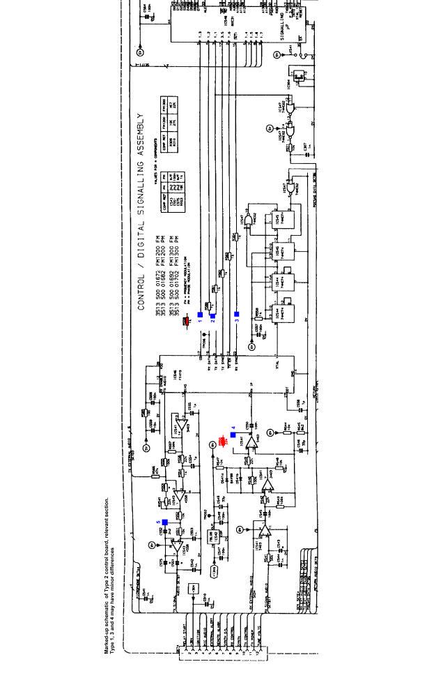
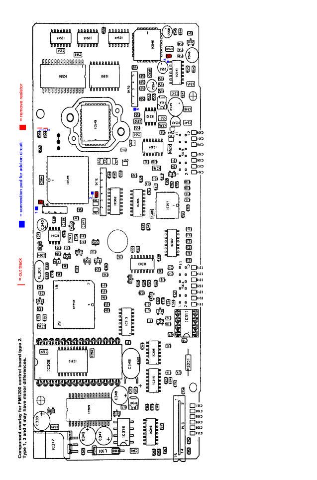
1 Conversion Manual for Philips FM1200 / 1300 VHF/UHF PMR with 12-button numeric keypad console By Jan Buiting, PE1CSI Philips PMR Collection pe1csi@amsat.org Summary This conversion developed by Dennis Koller PA4DEN is a follow-up of a simpler and less invasive conversion for 100 fixed channels developed by Gerrit Speelman PA1MT and described by Jan Buiting PE1CSI in Radio Today, September The conversion developed by Dennis PA4DEN is based on completely rewritten software for (1) main CPU, (2) tone CPU and (3) display CPU. It overcomes all restrictions of the original Philips firmware for FM1000 radios. Essentially, the conversion consist of the following steps: 1) replacement of the EPROM in de display console 2) removal of the trunking PROM, clearing PCB area 3) mounting a new SMD PROM 4) construction of two small auxiliary circuits for CTCSS / 5-tone generation and detection 5) replacement of the 24C16 EEPROM by a larger type 6) fitting the new radio firmware (moulded 28- pin module) Although it should be possible to carry out the conversion by referring to the schematics only. the conversion is described below in a step by step manner. How it works The following discussion makes reference to the schematic of the conversion circuit. Essentially, two small add-on audio circuits within the dashed area are connected to processor lines formerly used by the internal FFSK modem IC type FX419 (which is no longer used). CTCSS tones are generated by the tone CPU using PWM (pulsewidth modulation) and lookup tables stored in the tone PROM. The software-generated PWM signals are taken from processor port line P1.3 and applied to an R-C low-pass filter to recover the sinusoidal envelope waveform. The 5-tone, 1750 Hz and DTMF tones generated using CPU port lines P1.1 and P1.2 are summed using R560 and R561. All tone signal lines are brought together and then injected into the modulation amplifier via opamp IC543B. The 80C31 CPU 'reads' received tones via a level shifter stage built around the BC547 transistor. By removing feedback resistor R550, opamp IC541 supplies infinite gain thus converting analogue input signals at its input into quasi-digital pulses. However, because the pulses swing between 2V and 6V, further digitising is required to ensure a clean TTL swing of 0-5V, hence the addition of the BC547. The internal pull-up at the INT\ input of the 80C31 CPU acts as the collector resistor for the BC547. The fact that the input of the FX419 modem IC still receives speech and tone signals via C550 is of no consequence. Contents of Conversion Kit Resistor 47 kω Resistor 4.7 kω Resistor 82 kω Resistor 10 kω Resistor 1.8 kω Transistor BC549 or BC547 Capacitor 0.22 µf MKT EEPROM 24C65 or 24(L)C64, programmed with basic radio settings EPROM 27C256 or 27C128 (DIL28), programmed with Display Software PROM 27C256R (PLCC32), programmed with Tone Software Flash EEPROM module, moulded, programmed with Firmware Transparent film for display Marked-up circuit diagram of FM1200 control board Marked-up component overlay of FM1200 control board Schematic of conversion circuit User Manual FM1200 / 1100 / 1300 VHF/UHF Personal Mobile Radio Conversion Manual (this document Price of the Conversion Kit: UK: 25 incl. P&P Other countries: Euro 38 incl. P&P
2 Step-by-step conversion description The version number of the control board inside your FM1200 or FM1300 radio is either 1, 2, 3 or 4 as shown by the number printed in yellow in the top right hand corner of the board. On Version-1 control boards, pin 32 of the firmware EPROM socket has to be connected to pin 28, and the moulded module has to be mounted 'bottom-down', i.e., with module pins 14 and 15 inserted in socket pins 16 and 17 respectively. Only version-1 boards have a 32- way PLCC socket for the trunking PROM (position IC549). This socket obviates PROM removal and all soldering work as described under 4) and 5) below since the old PROM is simply pulled from the socket and the new one inserted. Warning. When handling integrated circuits, take precautions against static discharges. 1. Disassemble the display console and fit the new EPROM (marked display ) from the Conversion Kit. For 27C128/256 only: relocate track jumper LK4 to left-hand position. Fit the new transparent film. Reassemble the display console. 2. Remove the control board from the radio. 3. Check the position of the wire link near the trunking PROM IC549. The centre pad should be (re)connected to ground. 4. Remove the existing 27C256R PROM in position IC549. On control boards types 2, 3 and 4 a plastic anti-tamper cap has to be removed first. The IC itself is best removed using a small circular cutter (mini Flex), which is applied such that the pins are severed from all four sides of the IC body. In this process the PROM body may be destroyed without problems. The PROM pins left behind on the PCB are removed one by one using the solder iron tip. Next, smoothen the surface of the underlying PCB pads with the solder iron only. Do not use desoldering braid, as it will totally absorb the small amount of solder flux residue needed to solder in the new IC. 5. Mount the 27C256R PROM marked 'T' from the Conversion Kit. Position the PROM so that the hole (pin 1) is at the side of the nearby 80C31 processor. An SMD solder iron (max. power 15 watts) will be required. Carefully align the PROM on the underlying solder pads. Start by soldering one (corner) pin to get the device provisionally fixed in place, then re-check alignment and reposition if necessary. Use a continuity tester and the PROM check-up diagram and table to verify proper connections of all PROM pins with the circuit. Also check for short circuits between PROM pins. 6. Remove the 24C16 EEPROM (IC311) and replace it with the 24C64, 24LC64 or 24C65 from the Conversion Kit. (not on control board type 1). 7. Remove the three SMD resistors marked in red on the component overlay drawing. 8. Cut the two tracks at the indicated locations on the component overlay drawing. These are very short tracks! Use your continuity tester or ohmmeter to make sure the tracks are effectively broken! 9. Now construct the two small circuits that appear within the dashed outline on the conversion schematic. The 7 components from the Conversion Kit are mounted on the control board using a flying lead construction. Be sure to keep the construction lower than the tops of the electrolytic capacitors on the board. Find suitable grounding points for the 0.22µF capacitor, the emitter of the BC547 and the 1.8kΩ resistor. Sufficient grounding points are available at the component side of the board. The blue squares on the component overlay drawing show the points where the auxiliary circuits are effectively connected. The number labels correspond with those shown in the conversion circuit schematic and the conversion board schematic. Use thin wire (wire-wrap) for the wire connections. 10. Use an ohmmeter and the circuit diagrams to check all wire connections and component connections within the added circuits. 11. Mount the converted control board into the radio chassis. 12. Remove the firmware EPROM 27C512 and mount the moulded Flash EEPROM module. Pin 1 of the module is marked with a white dot and a hole. Control board type 1 only: align the module 'bottom-down' in the 32-way socket. All other versions: the pin-1 marker on the module goes near the edge of the board. Testing 1. Hold any key pressed while switching on the radio. The radio should enter a special display test mode. Check LCD contrast,
3 LED functionality and normal appearance of all characters. 2. Switch off, wait approx. 2 seconds and switch on again. After about 3-5 seconds, the PA4DEN welcome/copyright text should appear. The radio is then ready for use. Notes 1. If the level of the transmitted CTCSS tones is too low, the value of the series resistor (47 kω) resistor may be lowered to approx. 22 kω. 2. When in text entry mode, if you see a long string of random characters these should be removed first by keeping the yellow button pressed. 3. You are kindly requested to send the two 27C512 EPROMs and the 24C16 EEPROM removed from the radio to Mr. J. Buiting, Segment b.v., FREEPOST, CCRI Numero 1, NL-6160-VK, Beek, THE NETHERLANDS. Postage is not required. The devices will be used to help other radio amateurs having opted for the 'simple' conversion. Thank you. 4. Do not discard the plastic container for the moulded Flash module. The container should be used to protect the module when returning it for an update (if available). 5. Software updates (firmware module) are only available directly from Dennis Koller, PA4DEN, pa4den@hotmail.com. 6. Attempts to read the firmware module using an EPROM programmer may cause damage due to improper voltages being applied to the internal Flash device. The firmware will not run from EPROM. Warning Never key the transmitter without a 70-cm antenna or dummy load connected to the radio. Schematic of conversion circuit. The added components are within the dashed area
4 - 4 -
5 - 5 -
RS cm transceiver
 RS9044 70cm transceiver ATF-2 Base-unit Modification Dennis Koller (PA4DEN) Schoollaan 2 8392 NM Boyl 0622379901 / 0561421557 1 The receiver Lets start with the receiver, this is the most difficult part.
S-Pixie QRP Kit. Student Manual. Revision V 1-0
 S-Pixie QRP Kit Student Manual Revision V 1-0 Introduction The Pixie 2 is a small, versatile radio transceiver that is very popular with QRP (low power) amateur radio operators the world over. It reflects
E L E C R A F T K N B 1 N O I S E B L A N K E R
 Introduction E L E C R A F T K N B N O I S E B L A N K E R Assembly and Operating Instructions Revision C, Jan. 8, 200. Copyright 200, Elecraft; All Rights Reserved The KNB noise blanker can be used to
CW-ADD. Universal CW Adapter for SSB Transceivers. Assembly manual. Last updated: October 1,
 CW-ADD Universal CW Adapter for SSB Transceivers Assembly manual Last updated: October 1, 2017 ea3gcy@gmail.com Updates and news at: www.ea3gcy.com Thanks for building the Universal CW Adapter kit CW-ADD
12V Dimmer Kit, version 2
 12V Dimmer Kit, version 2 User Manual Description The 12V Dimmer Kit V2 is an especially efficient PWM (pulse-width modulation) controller for 12V loads up to 60 watts. It features a single dial control
Assembly Instructions for B7971 Smart Socket
 Assembly Instructions for B7971 Smart Socket Identification and installation of the resistors, Fig1 Segment 1,R1, 22k Segment 4, R4, 22k Segment 2, R2, 27k Segment 3, R3, 27k Segment 5, R5, 27k Segment
Discrete Op-Amp Kit MitchElectronics 2019
 Discrete Op-Amp Kit MitchElectronics 2019 www.mitchelectronics.co.uk CONTENTS Introduction 3 Schematic 4 How It Works 5 Materials 9 Construction 10 Important Information 11 Page 2 INTRODUCTION Even if
Pacific Antenna - Easy TR Switch
 Pacific Antenna - Easy TR Switch Kit Description The Easy TR Switch is an RF sensing switch that can be used to switch an antenna between a receiver and transmitter. It also has a second switched pair
16 Bit Micro Experimenter Assembly and Check out Instructions
 16 Bit Micro Experimenter Assembly and Check out Instructions The kit you purchased that includes PCB, schematic, complete parts list and these assembly instructions. A top picture of the complete assembly
BP-1A. Band-Pass variable filter continuous tuning from 3 to 30MHz. For analogue or software-defined receivers (SDR) Assembly manual
 Assembly manual") BP-1A Band-Pass variable filter continuous tuning from 3 to 30MHz. For analogue or software-defined receivers (SDR) Assembly manual Last updated: December 1, 2017 ea3gcy@gmail.com Updates and news at:
BP-1A Band-Pass variable filter continuous tuning from 3 to 30MHz. For analogue or software-defined receivers (SDR) Assembly manual Last updated: December 1, 2017 ea3gcy@gmail.com Updates and news at:
TekBot Remote Control Receiver Board Construction
 TekBot Remote Control Receiver Board Construction Purpose This tutorial illustrates the procedure for construction of the Receiver board for the TekBot. A Guide to Soldering Many of you have soldered once
Build this Direct Digital Synthesizer "Development Kit" By: Diz Gentzow, W8DIZ
 Build this Direct Digital Synthesizer "Development Kit" By: Diz Gentzow, W8DIZ A great tutorial for adding a keypad to the DDS Kit by Bruce, W8BH This manual has been prepared to be read directly on screen.
Pacific Antenna Easy TR Switch
 Pacific Antenna Easy TR Switch Kit Description The Easy TR Switch is an RF sensing circuit with a double pole double throw relay that can be used to automatically switch an antenna between a separate receiver
LED Field Strength Indicator Kit
 LED Field Strength Indicator Kit Description The Field Strength Indicator kit from Qrpkits.com provides a visual way to monitor RF fields through the brightness of an LED. It will respond to RF fields
The Infinity Bug. This is an amazing project... Order kit Fully assembled version $199 Order Infinity Bug
 The Infinity Bug This is an amazing project... us$55.00 plus $6.50 post Order kit Fully assembled version $199 Order Infinity Bug The INFINITY BUG is connected across the phone-line of a distant phone
Assembly and User Guide
 Assembly and User Guide AtariPunkr is an adjustable stepped tone generator. AtariPunkr provides hours of fun everyone! Powered by: 9V Battery Outputs: Mylar Speaker (Included) Stereo Output (3.5mm Jack)
LBI-38392C IC DATA MAINTENANCE MANUAL LOGIC BOARD U707 OCTAL DATA LATCH 19D902172G1 & G2 TABLE OF CONTENTS
 LBI-38392C MAINTENANCE MANUAL LOGIC BOARD 19D902172G1 & G2 U707 OCTAL DATA LATCH IC DATA TABLE OF CONTENTS Page DESCRIPTION........................................... Front.. Cover CIRCUIT ANALYSIS........................................
Assembly Instructions
 Assembly Instructions For the SSQ-2F 3.1 MHz Rife Controller Board Kit v1.41 Manual v1.00 2012 by Ralph Hartwell Spectrotek Services GENERAL ASSEMBLY INSTRUCTIONS Arrange for a clean work surface with
Step by Step Building PJ meter ARDF Receiver Kit. CRKITS.COM August 5, 2013
 Step by Step Building PJ-80 80-meter ARDF Receiver Kit CRKITS.COM August 5, 2013 What is ARDF? ARDF is the abbreviation of Amateur Radio Direction Finding, or so called Fox Hunting. If you are looking
KK1L Icom Band Decoder Basic Assembly
 KK1L Icom Band Decoder Basic Assembly Ronald Rossi, KK1L http://home.comcast.net/~kk1l Features: RFI isolated inputs Fully opto-isolated Replaces one BCD band decode port on KK1L dual decoder Description:
HT-1A Dual Band CW QRP Transceiver. Kit Building Instructions
 HT-A Dual Band CW QRP Transceiver Kit Building Instructions Rev B, July 8, 08 Designed by BD4RG Exclusively distributed by CRKITS.COM and its worldwide distributors Join the group http://groups.io/g/crkits
Picture: Luit Popken PA0LPN Developed originally by G4WMX and GW3DIX, later improved by DK9NL. Latest improvements by DG0KW (version used by us)
") The X-Phase-2 QRM-killer Picture: Luit Popken PA0LPN Developed originally by G4WMX and GW3DIX, later improved by DK9NL. Latest improvements by DG0KW (version used by us) A hobby project of the local VERON
The X-Phase-2 QRM-killer Picture: Luit Popken PA0LPN Developed originally by G4WMX and GW3DIX, later improved by DK9NL. Latest improvements by DG0KW (version used by us) A hobby project of the local VERON
HEAT ACTIVATED SWITCH KIT
 TEACHING RESOURCES SCHEMES OF WORK DEVELOPING A SPECIFICATION COMPONENT FACTSHEETS HOW TO SOLDER GUIDE REACT TO THE TEMPERATURE WITH THIS HEAT ACTIVATED SWITCH KIT Version 2.1 Heat Activated Switch Teaching
Pacific Antenna Simple Keyer Kit
 Pacific Antenna Simple Keyer Kit Specifications and Features: Speed range of 5 to 30 wpm Operates in either iambic A or B mode, with B being the default 2 message memories Tune and Beacon modes Built on
Lighthouse Beginner s soldering kit
 Lighthouse Beginner s soldering kit Kit contains: 1 x 220 ohm resistor (Red, Red, Black) 1 x 82k ohm resistor (Grey, Red, Orange) 2 x 220k ohm resistors (Red, Red, Yellow) 2 x Diodes 1 x Power switch 1
Ultimaker UMO Cooling fan PWM Ultimainboard transistor BC817 Replacement
 Ultimaker UMO Cooling fan PWM Ultimainboard transistor BC817 Replacement Repair your own Ultimainboard (rev 2.1.1) PWM cooling fan T1 / T2 (type BC 817). Written By: L Sch ifixit CC BY-NC-SA www.ifixit.com
DIODE / TRANSISTOR TESTER KIT
 DIODE / TRANSISTOR TESTER KIT MODEL DT-100K 99 Washington Street Melrose, MA 02176 Phone 781-665-1400 Toll Free 1-800-517-8431 Visit us at www.testequipmentdepot.com Assembly and Instruction Manual Elenco
TKEY-1. CW touch key. (no electromechanical contacts) Assembly manual. Last update: May 1,
 Assembly manual. Last update: May 1,") TKEY-1 CW touch key (no electromechanical contacts) Assembly manual Last update: May 1, 2016 ea3gcy@gmail.com Updates and news at: www.qsl.net/ea3gcy Thanks for constructing the TKEY-1A CW touch key Have
TKEY-1 CW touch key (no electromechanical contacts) Assembly manual Last update: May 1, 2016 ea3gcy@gmail.com Updates and news at: www.qsl.net/ea3gcy Thanks for constructing the TKEY-1A CW touch key Have
Read This Page First
 Read This Page First If you are reading this you know the manuals are always available at QRPKITS.com. This is version 8.0 of the manual dated 4/27/2016. There is no need to print out the whole assembly
LED S METER CONSTRUCTION MANUAL. LED S meter Construction Manual Issue 1.0 Page 1
 LED S METER CONSTRUCTION MANUAL LED S meter Construction Manual Issue 1.0 Page 1 Important Please read before starting assembly STATIC PRECAUTION The LED S Meter kit contains components which can be damaged
BFoxCon Manual. Version 0.2 October 30, 2017
 Overview The Byonics BFoxCon is a radio controller board designed to pair with a Baofeng UV-5R to create a transceiver for hidden transmitter hunts, also called T-hunts, foxhunts, and ARDF. It mounts on
Tek-Bot Remote Control Transmitter Board Construction
 Tek-Bot Remote Control Transmitter Board Construction Purpose This tutorial illustrates the procedure for construction of the Transmitter board for the Tek-bot. A Guide to Soldering Many of you have soldered
Total solder points: 101 Difficulty level: beginner advanced ELECTRONIC WATCHDOG K2655 ILLUSTRATED ASSEMBLY MANUAL
 Total solder points: 101 Difficulty level: beginner 1 2 3 4 5 advanced ELECTRONIC WATCHDOG K2655 Listens and scares intruders with realistic barking. ILLUSTRATED ASSEMBLY MANUAL H2655IP-2 Features & Specifications
LBI-39061A. Installation Manual. DTMF Encoder 344A4209P23 (MHDE5U) ericssonz
 ericssonz") LBI-39061A Installation Manual DTMF Encoder 344A4209P23 (MHDE5U) ericssonz TABLE OF CONTENTS Page INTRODUCTION...3 GENERAL DESCRIPTION...3 PROGRAMMING...3 THEORY OF OPERATION...3 INSTALLATION AND ALIGNMENT...4
LBI-39061A Installation Manual DTMF Encoder 344A4209P23 (MHDE5U) ericssonz TABLE OF CONTENTS Page INTRODUCTION...3 GENERAL DESCRIPTION...3 PROGRAMMING...3 THEORY OF OPERATION...3 INSTALLATION AND ALIGNMENT...4
Assembly Instructions for the 1.5 Watt Amplifier Kit
 Assembly Instructions for the 1.5 Watt Amplifier Kit 1.) All of the small parts are attached to a sheet of paper indicating both their value and id. 2.) Leave the parts affixed to the paper until you are
Pacific Antenna Low Pass Filter Kit
 Pacific Antenna Low Pass Filter Kit Description Many basic transmitter and/or transceiver designs have minimal filtering on their output and frequently have significant harmonic content in their signals.
V-TUNE. Variable capacitance mini-circuit with Varactor diode and potentiometer control. Assembly manual. Last updated: July 15, 2017
 V-TUNE Variable capacitance mini-circuit with Varactor diode and potentiometer control Assembly manual Last updated: July 15, 2017 ea3gcy@gmail.com Updates and news at: www.ea3gcy.com Thanks for building
Pacific Antenna Field Strength Indicator Kit
 Pacific Antenna Field Strength Indicator Kit Description The Field Strength Indicator kit from Pacific Antenna provides a visual way to monitor the presence and relative strength RF fields through the
Temperature activated switch
 Build instructions, circuit explanation and example applications Issue 1.5 Product information: www.kitronik.co.uk/quicklinks/2113/ TEACHER Temperature activated switch Introduction About the project kit
D.I.Y L.E.D CUBE 4X4X4. Level: Intermediate
 EN D.I.Y L.E.D CUBE 4X4X4 Level: Intermediate AK-125 TABLE OF CONTENTS Parts List... 2 Soldering Guide (Part A)... 3 Soldering Guide (Part B)... 5 Soldering Guide Without Recommend Products... 8 Appendix...
Total solder points: 338 Difficulty level: beginner advanced. Remote control by telephone K6501 ILLUSTRATED ASSEMBLY MANUAL
 Total solder points: 338 Difficulty level: beginner 1 2 3 4 5 advanced Remote control by telephone K6501 Operate your appliances from anywhere with a simple phone call. ILLUSTRATED ASSEMBLY MANUAL H6501IP-1
Installation tutorial for Console Customs Xbox ONE MaxFire ONE V2 PCB
 Installation tutorial for Console Customs Xbox ONE MaxFire ONE V2 PCB This tutorial is designed to aid you in installation of a console customs MaxFire ONE V2 Circuit board in the newer Xbox One Controllers
QRPGuys SMT Digital Dial/Frequency Counter
 QRPGuys SMT Digital Dial/Frequency Counter First, familiarize yourself with the parts and check for all the components. If a part is missing, please contact us and we will send one. You must use qrpguys.parts@gmail.com
Technical Specifications - Characteristics
 Watt FM TRANSMITTER General Description This is a small but quite powerful FM transmitter having three RF stages incorporating an audio preamplifier for better modulation. t has an output power of 4 Watts
Quick Response Alarm. Version Printings
 Quick Response Alarm Version 1.00 Printings Version 1.00: 01/07/2005 TABLE OF CONTENTS SPECIFICATIONS... 1 1.0 GENERAL DESCRIPTION... 2 1.1 Description... 2 1.2 Capabilities and Features... 2 1.3 Operation...
IC-765: Installing the Inrad Roofing Filter Mod
 IC-765: Installing the Inrad Roofing Filter Mod The Icom IC-765 roofing filter mod consists of a 6-pole, 4 khz wide filter followed by a high dynamic range, feedback amplifier. The amplifier provides enough
3. Assembly manual ANALYZING THE PCB'S LCD PCB. Component side: Solder side:
 3. Assembly manual ANALYZING THE PCB'S LCD PCB Component side: Solder side: MAIN PCB Component side: Solder side: ASSEMBLGING THE LCD PCB 1. Resistor R1: 33 Ohm (orange, black, black) 2. 6 Pin female header
C S Technology Ltd. cstech.co.uk. DTMF decoder kit with relay output, opto coupled input & Morse transpond.
 C S Technology Ltd cstech.co.uk DTMF decoder kit with relay output, opto coupled input & Morse transpond. Our DTMF Opto decoder kit has one relay output offering clean contacts, and one Opto coupled input
DIODE / TRANSISTOR TESTER KIT
 DIODE / TRANSISTOR TESTER KIT MODEL DT-100K Assembly and Instruction Manual Elenco Electronics, Inc. Copyright 1988 Elenco Electronics, Inc. Revised 2002 REV-K 753110 DT-100 PARTS LIST If you are a student,
Modification of USB Sound Card for Asterisk app_rpt Use
 Modification of USB Sound Card for Asterisk app_rpt Use First off a huge thank you to Steve for providing the original notes on how to modify a USB sound card. (http://images.qrvc.com/usbfob.pdf) These
HAMTRONICS TD-5 SUBAUDIBLE TONE ENCODER/DECODER: ASSEMBLY, INSTALLATION, AND OPERATION
 HAMTRONICS TD-5 SUBAUDIBLE TONE ENCODER/DECODER: ASSEMBLY, INSTALLATION, AND OPERATION CAUTION. The TD-5 contains static sensitive ic's, which require normal static prevention techniques when handling
8x8 Red Blue Green Yellow Audio Indicator
 8x8 Red Blue Green Yellow Audio Indicator 1. Introduce. 1>. Working voltage: 5V. 2>. PCB size: 75*45mm. 3>. There are four fixed mounting holes on PCB. 4>. It is no need for filter circuit. It can driver
Bi-Directional DC Motor Speed Controller 5-32Vdc (3166v2)
") General Guidelines for Electronic Kits and Assembled Modules Thank you for choosing one of our products. Please take some time to carefully read the important information below concerning use of this product.
General Guidelines for Electronic Kits and Assembled Modules Thank you for choosing one of our products. Please take some time to carefully read the important information below concerning use of this product.
DuoDrive Nixie Bargraph Kit
 Assembly Instructions And User Guide Nixie Bargraph Kit - 1 - REVISION HISTORY Issue Date Reason for Issue Number 1 12 December 2017 New document - 2 - 1. INTRODUCTION 1.1 About Nixie Bargraph Driver IN-9
Total solder points: 82 Difficulty level: beginner advanced. Dc to Pulse Width Modulator K8004 ILLUSTRATED ASSEMBLY MANUAL
 Total solder points: 82 Difficulty level: beginner 1 2 3 4 5 advanced Dc to Pulse Width Modulator K8004 Allows very efficient control of DC motors, heaters or lights. ILLUSTRATED ASSEMBLY MANUAL H8004IP-2
FM RADIO KIT ESSENTIAL INFORMATION. Version 2.0 GET IN TUNE WITH THIS
 ESSENTIAL INFORMATION BUILD INSTRUCTIONS CHECKING YOUR PCB & FAULT-FINDING MECHANICAL DETAILS HOW THE KIT WORKS GET IN TUNE WITH THIS FM RADIO KIT Version 2.0 Build Instructions Before you start, take
10W Class D Ultra Stereo Amplifier Kit
 1 Total Solder Joints: 70 Difficulty Level : beginner expert PARADIGM Technologies (UK) Ltd Electronic Kits and Modules 10W Class D Ultra Stereo Amplifier Kit K1421 High power / quality audio amplifier
MINI FM PHONE TRANSMITTER KIT
 MINI FM PHONE TRANSMITTER KIT Description: This is a subminiature FM telephone transmitter capable of transmitting both sides of a telephone conversation to most any FM receiver up to 1/4 mile away. When
555 Morse Code Practice Oscillator Kit (draft 1.1)
") This kit was designed to be assembled in about 30 minutes and accomplish the following learning goals: 1. Learn to associate schematic symbols with actual electronic components; 2. Provide a little experience
This kit was designed to be assembled in about 30 minutes and accomplish the following learning goals: 1. Learn to associate schematic symbols with actual electronic components; 2. Provide a little experience
Assembly and Operating Instructions. Revision D, Aug. 20, Copyright 2002, Elecraft; All Rights Reserved
 Introduction E L E C R A F T K N B N O I S E B L A N K E R Assembly and Operating Instructions Revision D, Aug. 0, 00. Copyright 00, Elecraft; All Rights Reserved The KNB noise blanker can be used to suppress
STEP 0 Prepare the Materials.
 How to Build a Germanium Fuzz Guitar Effect. This document will guide you to build and test your Germanium Fuzz guitar pedal. With all the materials on hand, it takes around 2-4 hours to build it. Try
SSRP LTC1746 Assembly Manual V0.1 Check the most recent version
 SSRP LTC1746 Assembly Manual V0.1 Check the most recent version http://oscar.dcarr.org/ssrp/hardware/ltc1746/ltc1746.php Introduction This manual details the general assembly process for the SSRP LTC1746
MPC-XU Universal Crossover
 MPC-U Universal Crossover For JBL MPC and MPA amplifiers Owner s Manual and Installation Guide I. Description The MPC-U is a dual-channel universal crossover filter accessory for use with JBL MPC and MPA
SoftRock v6.0 Builder s Notes. May 22, 2006
 SoftRock v6.0 Builder s Notes May 22, 2006 Be sure to use a grounded tip soldering iron in building the v6.0 SoftRock circuit board. The soldering iron needs to have a small tip, (0.05-0.1 inch diameter),
Simple and cheap OPC-478 interface roomed into a DB9 by Maurizio Malaspina (IW6DFW), April 2008
, April 2008") Simple and cheap OPC-478 interface roomed into a DB9 by Maurizio Malaspina (IW6DFW), April 2008 Building this simple circuit you will be able to link your Icom radio to PC to either remotely control your
Simple and cheap OPC-478 interface roomed into a DB9 by Maurizio Malaspina (IW6DFW), April 2008 Building this simple circuit you will be able to link your Icom radio to PC to either remotely control your
SPACE WAR GUN KIT MODEL K-10. Assembly and Instruction Manual. Elenco Electronics, Inc.
 SPACE WAR GUN KIT MODEL K-10 Assembly and Instruction Manual Elenco Electronics, Inc. Copyright 1989 Elenco Electronics, Inc. Revised 2001 REV-H 753210A PARTS LIST Contact Elenco Electronics (address/phone/e-mail
Assembly Manual V1R2B-Rev1.0D
 Assembly Manual V1R2B-Rev1.0D for 4 State QRP MagicBox - Solid State Transmit/Receive System Designed by: Jim Kortge, K8IQY Copyright 2009-2012 - All rights reserved This system is the result of some brainstorming
Modifying a USB sound fob to act as a repeater interface for app_rpt
 Modifying a USB sound fob to act as a repeater interface for app_rpt This document explains how to modify a USB sound fob to work as a repeater interface for app_rpt. The following materials and tools
µpad: Proto Base Manual
 µpad: Proto Base Manual Last Updated May 13, 2015 Table of Contents WARNING: READ BEFORE PROCEDING!... 7 Overview... Error! Bookmark not defined. µpad Base Connection... 8 Analog... 8 Amplifier Circuit...
10W Class D Stereo Amplifier Kit
 1 Total Solder Joints: 70 Difficulty Level : beginner expert 10W Class D Stereo Amplifier Kit PARADIGM Technologies (UK) Ltd Electronic Kits and Modules K1420 High power multipurpose audio amplifier Specifications
HAMTRONICS TB901 FM EXCITER INSTALLATION, OPERATION, & MAINTENANCE
 HAMTRONICS TB901 FM EXCITER INSTALLATION, OPERATION, & MAINTENANCE GENERAL INFORMATION. The TB901 is a single-channel low power fm transmitter (exciter) designed to provide 300-600 milliwatts continuous
ELECRAFT KXB and 80 METER ADAPTER
 ELECRAFT KXB3080 30 and 80 METER ADAPTER Assembly and Operating Instructions Revision B, May 16, 2012 Copyright 2012, Elecraft; All Rights Reserved i Your KX1 must have an 18-turn inductor installed at
1. Technical Specifications
 This document describes procedures that could result in voiding of the warranty of your radio. If these procedures are not precisely and properly carried out, it could result in a radio that does not work
TS-930: Installing the Inrad Roofing Filter Mod
 TS-930: Installing the Inrad Roofing Filter Mod The TS-930 roofing filter mod consists of a 6 pole, 4 to 5 khz wide filter followed by a high dynamic range, feedback amplifier. The amplifier provides enough
Pb-free lead plating; RoHS compliant
 Programmable Single-/Dual-/Triple- Tone Gong Pb-free lead plating; RoHS compliant SAE 800 Bipolar IC Features Supply voltage range 2.8 V to 18 V Few external components (no electrolytic capacitor) 1 tone,
IR add-on module circuit board assembly - Jeffrey La Favre January 27, 2015
 IR add-on module circuit board assembly - Jeffrey La Favre January 27, 2015 1 2 For the main circuits of the line following robot you soldered electronic components on a printed circuit board (PCB). The
MONO AMPLIFIER KIT ESSENTIAL INFORMATION. Version 3.0 CREATE YOUR OWN SPEAKER DOCK WITH THIS
 ESSENTIAL INFORMATION BUILD INSTRUCTIONS CHECKING YOUR PCB & FAULT-FINDING MECHANICAL DETAILS HOW THE KIT WORKS CREATE YOUR OWN SPEAKER DOCK WITH THIS MONO AMPLIFIER KIT Version 3.0 Build Instructions
HANDS-ON LAB INSTRUCTION SHEET MODULE 3 CAPACITORS, TIME CONSTANTS AND TRANSISTOR GAIN
 HANDS-ON LAB INSTRUCTION SHEET MODULE 3 CAPACITORS, TIME CONSTANTS AND TRANSISTOR GAIN NOTES: 1) To conserve the life of the Multimeter s 9 volt battery, be sure to turn the meter off if not in use for
Elektor Construction Guide TAPIR
 Elektor Construction Guide TAPIR The TAPIR is a three-dimensional assembly. To ensure good access to all soldering points, we recommend assembling the kit exactly according to the described sequence. 1
Construction notes for the symmetrical 400 watt amplifier
 Construction notes for the symmetrical 400 watt amplifier Introduction The symmetrical amplifier is an update of one of my designs, which appeared in the Australian electronics magazine Silicon Chip in
V6.2 SoftRock Lite Builder s Notes. November 17, 2006
 V6.2 SoftRock Lite Builder s Notes November 17, 2006 Be sure to use a grounded tip soldering iron in building the v6.2 SoftRock circuit board. The soldering iron needs to have a small tip, (0.05-0.1 inch
Bill of Materials: Metronome Kit PART NO
 Metronome Kit PART NO. 2168325 The metronome kit allows you to build your own working electronic metronome. Features include a small speaker, flashing LED, and the ability to switch between several different
DEPARTMENT OF ELECTRICAL ENGINEERING AND COMPUTER SCIENCE MASSACHUSETTS INSTITUTE OF TECHNOLOGY CAMBRIDGE, MASSACHUSETTS 02139
 DEPARTMENT OF ELECTRICAL ENGINEERING AND COMPUTER SCIENCE MASSACHUSETTS INSTITUTE OF TECHNOLOGY CAMBRIDGE, MASSACHUSETTS 02139 Spring 2017 V2 6.101 Introductory Analog Electronics Laboratory Laboratory
K8055N. USB Experiment interface board. Interface your computer with the world using 5 digital in and 8 outputs, 2 analogue in-and outputs.
 Total solder points: 313 Difficulty level: beginner 1 2 3 4 5 advanced USB Experiment interface board K8055N Interface your computer with the world using 5 digital in and 8 outputs, 2 analogue in-and outputs.
SERVICE BULLETIN. Description: VOX\ICS Tie Line Subassembly Document #: AMS44\603-0 Service Bulletin #: 002
 SERVICE BULLETIN NAT Part #: AMS44 Description: VOX\ICS Tie Line Subassembly Document #: AMS44\603-0 Service Bulletin #: 002 1. Planning Information 1.1 Applicability All dual channel audio controllers:
1. Technical Specifications
 This document describes procedures that could result in voiding of the warranty of your radio. If these procedures are not precisely and properly carried out, it could result in a radio that does not work
Construction Guide European Version
 Construction Guide European Version PCB This section describes how to build up the DRO-350 printed circuit board (PCB). The bare PCB is available for purchase on the order page. Static Protection Bare
TS-850: Installing the Inrad Roofing Filter Mod
 TS-850: Installing the Inrad Roofing Filter Mod The TS-850 Roofing Filter Mod consists of a 6 pole, 4 to 5 khz wide filter followed by a high dynamic range feedback amplifier. The amplifier provides enough
Simple LFO Features. 2. Application. 3. Description. Simple and easy to build LFO module for Analog Synthesizers.
 Simple LFO. Simple and easy to build LFO module for Analog Synthesizers.. Features Square and Triangle waveforms (90 phase shifted) Dual range frequencies Frequency ranges from under Hz up to several khz
Rangemaster Treble Booster Kit Building Manual
 Rangemaster Treble Booster Kit Building Manual Effect Pedal Kits: Rangemaster Treble Booster The Dallas Rangemaster is the most famous treble booster effect pedal, and it was the first pedal of its kind.
Raygun. Vector Weapon. projects. Raygun vector weapon. Build a mini analog sound-effects circuit. By Symetricolour. Time: 2 4 hours CosT: $15 $20
 projects Raygun vector weapon Raygun Vector Weapon By Symetricolour Time: 2 4 hours CosT: $5 $20 Build a mini analog sound-effects circuit. Gregory Hayes 02 Materials» raygun Vector Weapon Kit item #MSVWP
Chapter 15: Serial Controlled (HF) Radio Support
 Radio Support") 15-1 Chapter 15: Serial Controlled (HF) Radio Support This section describes the controller's interface for serial controlled radios. Most such radios are for the HF bands, but some such as the FT-736
15-1 Chapter 15: Serial Controlled (HF) Radio Support This section describes the controller's interface for serial controlled radios. Most such radios are for the HF bands, but some such as the FT-736
upad Proto Base Assembly Guide v2.0
 upad Proto Base Assembly Guide v2.0 Last Updated September 1, 2015 Table of Contents Preface... 3 Introduction... 3 Required Tools... 3 Flux Pen... 3 Soldering Iron... 3 Solder... 3 Diagonal Cutters...
+YODO +'4+EY 2ADIO +(4.OKIA ($ -ODIFICATIONS FOR AMATEUR RADIO USE
 'ENERAL This handheld radio is also known as names above. It has been designed to be used in trunking networks, equipped with Fylde Microsystems trunking logic board. Trunking systems are usually using
Electronic Components
 Electronic Components Arduino Uno Arduino Uno is a microcontroller (a simple computer), it has no way to interact. Building circuits and interface is necessary. Battery Snap Battery Snap is used to connect
Please read these instructions completely before you begin to do any work to the unit!
 This small release note will explain the function of the MFWM () and also provide some guidance building it into you FW-1884. Please note you really need basic mechanical and (de)soldering skills since
Light activated switch
 Build instructions, circuit explanation and example applications Issue 1.6 Product information: www.kitronik.co.uk/quicklinks/2112/ TEACHER Light activated switch Introduction About the project kit This
BAT BEACON A project of the Service Kring JOTA-JOTI. Manual Bat Beacon kit.
 Manual Bat Beacon kit. Pagina 1 van 12 A project of the. Do you like the Bat-Beacon, do you have great ideas? Tell us, please see how on the last page. Manual Bat Beacon kit.... 1 Remarks... 2 Introduction...
DIY Function Generator XR2206
 DIY Function Generator XR2206 20Hz 100KHz http://radiohobbystore.com Components List: Resistors: R1, R2 1% Metal Film 5K1 R4 1% Metal Film 10K R5 1% Metal Film 3K R10 5% Carbon Film 10R R3, R9 Potentiometer
Junior Digital circuit experiment board. Use for the experimentation of digital circuits both TTL IC and CMOS DC supply :
 NX-100plus Junior Digital circuit experiment board Feature Use for the experimentation of digital circuits both TTL IC and CMOS DC supply : +5V and +V (+12V approx. depend on DC adaptor) 800mA buit-in