Basics overview of Optical networking. Kurosh, August/2014
|
|
|
- Esther Parks
- 6 years ago
- Views:
Transcription

1 Basics overview of Optical networking Kurosh, August/2014
2 Agenda Basic optical terminologies (fiber and DWDM device) DWDM building blocks and enabling technologies Terrestrial deployments Submarine deployment OTN overview
3 Some terminology Decibels (db): unit of level (relative measure) X db is 10 -X/10 in linear dimension e.g. 3 db Attenuation = = Standard logarithmic unit for the ratio of two quantities. In optical fibers, the ratio is power and represents loss or gain. Decibels-milliwatt (dbm) : Decibel referenced to a milliwatt X mw is 10 log 10 (X) in dbm, Y dbm is 10 Y/10 in mw. 0dBm=1mW, 17dBm = 50mW Wavelength ( ): length of a wave in a particular medium. Common unit: nanometers, 10-9 m (nm) 300nm (blue) to 700nm (red) is visible. In fiber optics primarily use 850, 1310, & 1550nm Frequency ( ): the number of times that a wave is produced within a particular time period. Common unit: TeraHertz, cycles per second (Thz) Wavelength x frequency = Speed of light x = C Source: Cisco
4 Some more terminology Attenuation = Loss of power in db/km The extent to which lighting intensity from the source is diminished as it passes through a given length of fiber-optic (FO) cable, tubing or light pipe. This specification determines how well a product transmits light and how much cable can be properly illuminated by a given light source. Chromatic Dispersion = Spread of light pulse in ps/nm-km The separation of light into its different coloured rays. ITU Grid = Standard set of wavelengths to be used in Fibre Optic communications. Unit Ghz, e.g. 100Ghz, 50GHz Optical Signal to Noise Ration (OSNR) = Ratio of optical signal power to noise power for the receiver Lambda = Name of Greek Letter used as Wavelength symbol ( ) Optical Supervisory Channel (OSC) = Management channel
5 Bit Error Rate ( BER) BER is a key objective of the Optical System Design Goal is to get from Tx to Rx with a BER < BER threshold of the Rx BER thresholds are on Data sheets Typical minimum acceptable rate is 10E-12 for non DSP enhanced DWDM deployments.
6 Optical Budget Basic Optical Budget = Output Power Input Sensitivity Pout = +6 dbm R = -30 dbm Budget = 36 db Optical Budget is affected by: Fiber attenuation Splices Patch Panels/Connectors Optical components (filters, amplifiers, etc) Bends in fiber Contamination (dirt/oil on connectors)


7 Fiber Fundamentals Light is a form of electro-magnetic radiation which is characterized by having a particular wavelength and frequency. Attenuation Dispersion Nonlinearity It May Be a Digital Signal, but It s Analog Transmission Transmitted Data Waveform Waveform After 1000 Km
 EDFA band 1600 1700 20 10 0-10 -20 G652 G653 G654 Single Mode dispersion optimized at 1310nm G652B, G652C and G652D (Low water")
8 Attenuation (db/km) Dispersion (ps/nm km) Fiber standards shifted fiber unshifted fiber Wavelength (nm) EDFA band G652 G653 G654 Single Mode dispersion optimized at 1310nm G652B, G652C and G652D (Low water Dispersion Shifted Fiber G655 Non Zero Dispersion Shifted Fiber G657.A/B (Low Band-loss) Hole-assisted fiber (HAF) Photonic band-gap fiber (PBGF) Cutoff Shifted Fiber
9 Fiber nonlinearities Category 1: Occurs because of scattering effects in the fiber medium due to the interaction of light waves with phonons (molecular vibrations) in the silica medium. (next slide) Category 2: Dependence of refractive index on the optical power. (Have negative impact on DWDM) Self-Phase Modulation Cross-Phase Modulation Four-Wave Mixing 19. desember
10 Fiber nonlinearities and Scattering Linear Scattering Loss Rayleigh Scattering: It results from the non-homogeneities of the random nature occurring on a small scale particles compared with the wavelength of the light. Mie Scattering: It results from the non-homogeneities of the random nature occurring on a large scale particles compared with the wavelength of the light. It is usually in the forward direction. Non Linear Scattering Loss: Energy gets transferred from one light wave to another wave at a longer wavelength (or lower energy). The lost energy is absorbed by the molecular vibrations, or phonons, in the medium. Pump and stokes wave: As the pump propagates in the fiber, it loses power and the Stokes wave gains power Stimulated Brillouin: pump wave is the signal wave, and the Stokes wave is the unwanted wave stimulated Raman scattering: the pump wave is a high-power wave, and the Stokes wave is the signal wave that gets amplified at the expense of the pump wave. 19. desember

11 Attenuation Kilde: NSN ACADEMY

12 Optical Spectrum Kilde: NSN ACADEMY
13 DWDM: building blocks and enabling technologies 19. desember
14 Why DWDM The Business Case 40km Conventional TDM Transmission 10 Gbps 40km 40km 40km 40km 40km 40km 40km 40km TERM TERM RPTR 1310 RPTR 1310 RPTR 1310 RPTR 1310 RPTR 1310 RPTR 1310 RPTR 1310 RPTR 1310 TERM RPTR 1310 RPTR 1310 RPTR 1310 RPTR 1310 RPTR 1310 RPTR 1310 RPTR 1310 RPTR 1310 TERM RPTR 1310 RPTR 1310 RPTR 1310 RPTR 1310 RPTR 1310 RPTR 1310 RPTR 1310 RPTR 1310 RPTR RPTR RPTR RPTR RPTR RPTR RPTR RPTR TERM TERM TERM TERM OC-48 OC-48 OC-48 OC-48 OA DWDM Transmission 10 Gbps 120 km 120 km 120 km OA OA OA OC-48 OC-48 OC-48 OC-48 4 Fibers Pairs 32 Regenerators 1 Fiber Pair 4 Optical Amplifiers
15 DWDM History Early WDM (late 80s) Two widely separated wavelengths (1310, 1550nm) Second generation WDM (early 90s) Two to eight channels in 1550 nm window 400+ GHz spacing DWDM systems (mid 90s) 16 to 40 channels in 1550 nm window 100 to 200 GHz spacing Today s DWDM systems 160 channels in 1550 nm window (e.g. Siemens 160 and Alcatel 192 channels) 50 and 25 GHz spacing
16 Characteristics of a WDM Network Sub-wavelength Multiplexing or MuxPonding Ability to put multiple services onto a single wavelength
17 Characteristics of a WDM Network Wavelength Characteristics Transparency Monitori Can carry multiple protocols on same fiberng can be aware of multiple protocols Wavelength spacing 50GHz, 100GHz, 200GHz Defines how many and which wavelengths can be used Wavelength capacity Example: 1.25 Gbit/s, 2.5 Gbit/s, 10 Gbit/s, 40 Gbit/s, 100Gbit/s
18 Optical Transmission Bands and DWDM grid Band Wavelength (nm) New Band S-Band C-Band L-Band U-Band ad/repository/itu-dwdm.pdf
19 DWDM Components 850/ xx n Transponder 3 Optical Multiplexer n Optical De-multiplexer Band- and Channel Mux/Demux Optical Add/Drop Multiplexer (OADM)
20 More DWDM Components Optical Amplifier (EDFA) Optical Attenuator Variable Optical Attenuator Dispersion Compensator (DCM / DCU)
21 Typical DWDM Network Architecture DWDM SYSTEM DWDM SYSTEM VOA EDFA DCM DCM EDFA VOA Service Mux (Muxponder) Service Mux (Muxponder)
22 Transponders Converts broadband optical signals to a specific wavelength via optical to electrical to optical conversion (O-E-O) Used when Optical LTE (Line Termination Equipment) does not have tight tolerance ITU optics Performs 2R or 3R regeneration function Receive Transponders perform reverse function OEO 1 From Optical OLTE OEO 2 To DWDM Mux n OEO Low Cost IR/SR Optics Wavelengths Converted

23 Laser transponders Power Non DWDM Laser Fabry Perot on client side c DWDM Laser Distributed Feedback (DFB) On line sdie Power c Spectrally broad Unstable center/peak wavelength Dominant single laser line Tighter wavelength control Mirror Partially transmitting Mirror Active medium Amplified light
24 DWDM Receiver Requirements I Receivers Common to all Transponders Not Specific to wavelength (Broadband)


25 Attenuation and amplifiers P in G P out = GP in 19. desember
26 Optical Attenuation Pulse amplitude reduction limits how far Attenuation in db Power is measured in dbm: P i P 0 T T
 EDFA")


27 Combating attenuation SOA (Semiconductor Optical Amplifier) EDFA (Erbium Doped Fiber Amplifiers) SOA RAMAN (based on Stimulated Raman Scattering (SRS) EDFA TX Er 3+ doped Fiber RX pump 980nm TX Transmission Fiber RX RAMAN pump Raman 1535


.")

28 Erbium Doped Fiber Amplifier Isolator Coupler Coupler Isolator Erbium-Doped Fiber (10 50m) Pump Laser Pump Laser Simple device consisting of four parts: Erbium-doped fiber An optical pump (to invert the population). A coupler An isolator to cut off backpropagating noise Amplified Spontaneous Emission (ASE) is main source of noise in EDFA

29 OA Gain and Fiber Loss Typical Fiber Loss 25 THz 4 THz OA Gain OA gain is centered in 1550 window OA bandwidth is less than fiber bandwidth
30 Raman Amplifiers Raman Fibre Amplifiers (RFAs) rely on an intrinsic nonlinearity in silica fibre Variable wavelength amplification: Depends on pump wavelength For example pumping at 1500 nm produces gain at about nm RFAs can be used as a standalone amplifier or as a distributed amplifier in conjunction with an EDFA
31 Distributed Raman Amplification (I) Raman pumping takes place backwards over the fibre Gain is a maximum close to the receiver and decreases in the transmitter direction Long Fibre Span Transmitter EDFA Optical Receiver Raman Pump Laser
32 Optical Power Distributed Raman Amplification (II) With only an EDFA at the transmit end the optical power level decreases over the fibre length With an EDFA and Raman the minimum optical power level occurs toward the middle, not the end, of the fibre. EDFA + Raman EDFA only Distance Animation
33 Optical Signal-to Noise Ratio (OSNR) Signal Level X db Noise Level Depends on : Optical Amplifier Noise Figure: (OSNR) in = (OSNR) out NF EDFA Schematic (OSNR) (OSNR) out in P in NF Target : Large Value for X
34 Dispersions and Dispersion compensating modules 19. desember
 Single-mode fiber supports two polarization states Fast and slow axes have different group velocities Causes spreading of the light")
35 Types of Dispersion Chromatic Dispersion Different wavelengths travel at different speeds Causes spreading of the light pulse Polarization Mode Dispersion (PMD) Single-mode fiber supports two polarization states Fast and slow axes have different group velocities Causes spreading of the light pulse
36 Pulse Delay (ps) Dispersion Chromatic Dispersion (Review) + Pulse Spreading 0 Wavelength (nm) - 0 Wavelength Time Time Different Wavelengths of light travel at slightly different velocities in the glass fiber Negative ( normal ) dispersion: red light (longer ) faster Positive ( anomalous ) dispersion: blue light (shorter ) faster Leads to pulse broadening or distortion RBK-TWCable 6/97 Minimum dispersion at the Zero Dispersion Wavelength ( 0 ) 18 ps/(nm-km)
37 A Snapshot on Chromatic Dispersion Affects single channel and DWDM systems A pulse spreads as it travels down the fiber Inter-symbol Interference (ISI) leads to performance impairments Degradation depends on: laser used (spectral width) bit-rate (temporal pulse separation) Different SM types Interference
38 Limitations From Chromatic Dispersion Dispersion causes pulse distortion, pulse "smearing" effects Higher bit-rates and shorter pulses are less robust to Chromatic Dispersion Limits "how fast and how far 10 Gbps 60 Km SMF-28 t 40 Gbps 4 Km SMF-28 t
39 Combating Chromatic Dispersion Dispersion Compensating Fiber Dispersion compensating based on Fiber Bragg Grating (FBG) Transmitters with narrow spectral width Use DSF and NZDSF fibers with negative and positive dispersion coeffisient (G.653 & G.655)
40 Dispersion Compensating Fiber Dispersion Compensating Fiber: By joining fibers with CD of opposite signs (polarity) and suitable lengths an average dispersion close to zero can be obtained; the compensating fiber can be several kilometers and the reel can be inserted at any point in the link, at the receiver or at the transmitter
41 Fiber Bragg Grating This is invented at Communication Research Center, Ottawa, Canada The FBG has changed the way optical filtering is done The FBG has so many applications The FBG changes a single mode fiber (all pass filter) into a wavelength selective filter
42 Fiber Brag Grating (FBG) Basic FBG is an in-fiber passive optical band reject filter FBG is created by imprinting a periodic perturbation in the fiber core The spacing between two adjacent slits is called the pitch Grating play an important role in: Wavelength filtering Dispersion compensation Optical sensing EDFA Gain flattening Single mode lasers and many more areas
43 Bragg Grating formation 2 sin( / 2) uv
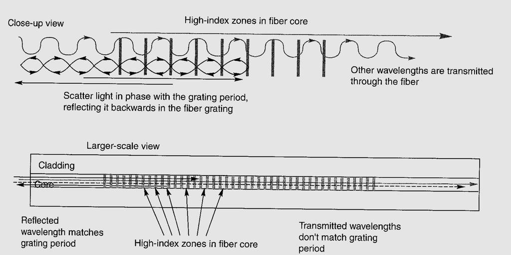
44 Reflection at FBG
45 Dispersion Compensation Longer wavelengths take more time Reverse the operation of dispersive fiber Shorter wavelengths take more time
46 Cumulative Dispersion (ps/nm) Dispersion Compensation Total Dispersion Controlled No Compensation With Compensation Distance from Transmitter (km) Transmitter Dispersion Compensators Dispersion Shifted Fiber Cable
47 Dispersion compensating by fiber management large mode field (LMF) fiber high dispersion fiber (HDF), also called dispersion shifted fiber nondispersion shifted fiber (NDSF) 19. desember
48 How Far Can I Go Without Dispersion? Distance (Km) = Specification of Transponder (ps/nm) Coefficient of Dispersion of Fiber (ps/nm*km) A laser signal with dispersion tolerance of 3400 ps/nm is sent across a standard SMF fiber which has a Coefficient of Dispersion of 17 ps/nm*km. It will reach 200 Km at maximum bandwidth. Note that lower speeds will travel farther.
 External stress (trucks) Only discovered in the 90s Most older fiber not")
49 Polarization Mode Dispersion All electromagnetic waves are Characterized by polarization In Which the electric field (E) of The wave is oscillating. Caused by ovality of core due to: Manufacturing process Internal stress (cabling) External stress (trucks) Only discovered in the 90s Most older fiber not characterized for PMD

50 Polarization Mode Dispersion (PMD) Ey n x Ex Pulse As It Enters the Fiber n y Differential group delay DGD (Δτ) DGD is measured in ps/ km Spreaded Pulse As It Leaves the Fiber The optical pulse tends to broaden as it travels down the fiber; this is a much weaker phenomenon than chromatic dispersion and it is of little relevance at bit rates of 10Gb/s or less According standard: DGD shouldn't exceed 30% of the bit period or DGDmax (30ps for 10Gbit/s or 7,5ps for 40Gbit/s). BUT when designing link the overall PMD(DGD) shouldn t exceed 1/3 (safety factor) of DGDmax < 0.06 ps/sqrt(km)
51 Combating Polarization Mode Dispersion Factors contributing to PMD Bit Rate Fiber core symmetry Environmental factors Bends/stress in fiber Imperfections in fiber Solutions for PMD Improved fibers Regeneration Follow manufacturer s recommended installation techniques for the fiber cable

 (From Various Sources) t t s Optimum Sampling Time t t s")
52 The 3 R s of Optical Networking A Light Pulse Propagating in a Fiber Experiences 3 Type of Degradations: Pulse as It Enters the Fiber Pulse as It Exits the Fiber Loss of Energy Shape Distortion Phase Variation Loss of Timing (Jitter) (From Various Sources) t t s Optimum Sampling Time t t s Optimum Sampling Time
 The Options to Recover the Signal from Attenuation/Dispersion/Jitter Degradation Are: Pulse as It")

53 The 3 R s of Optical Networking (Cont.) The Options to Recover the Signal from Attenuation/Dispersion/Jitter Degradation Are: Pulse as It Enters the Fiber Pulse as It Exits the Fiber Amplify to Boost the Power Re-Shape DCU Phase Variation Phase Re-Alignment Re-Generate t t s Optimum Sampling Time t t s Optimum Sampling Time O-E-O Re-gen, Re-shape and Remove Optical Noise t s Optimum Sampling Time t
54 19. desember


55 Multiplexer / Demultiplexer DWDM Mux DWDM Demux Wavelength Multiplexed Signals Wavelength Multiplexed Signals Wavelengths Converted via Transponders Wavelengths separated into individual ITU Specific lambdas
56 (De)Multiplxer technologies Dielectric filters FBG Free Space Diffraction Grattings Mach-Zehnder based devices Arrayed Waveguide Grating (AWG) 19. desember
57 Optical Filter Technology Thin-Film Filter 1, 2, 3,... n Dielectric Filter 2 1,, 3,... n Well established technology, up to 200 layers


58 Array Waveguide Grating Mux/Demux Fiber4sale.com
59 Array Waveguide Operation An Array Waveguide Demux consists of three parts : 1st star coupler, Arrayed waveguide grating with the constant path length difference 2nd star coupler. The input light radiates in the 1st star coupler and then propagates through the arrayed waveguides which act as the discrete phase shifter. In the 2nd star coupler, light beams converges into various focal positions according to the wavelength. Low loss, typically 6 db Dublin institute of technology
60 Simple De-multiplexing Function Reflected Wavelength 2 n Peak Reflectivity R max = tanh 2 (kl) B eff

61 Optical Add/Drop Filters (OADMs) OADMs allow flexible add/drop of channels Drop Channel Drop & Insert Add Channel Pass Through loss and Add/Drop loss
62 Extended Add/Drop Mux

63 ROADM node 19. desember
64 Transmission Errors Errors happen! A old problem of our era (PCs, wireless ) Bursty appearance rather than distributed Noisy medium (ASE, distortion, PMD ) TX/RX instability (spikes, current surges ) Detect is good, correct is better Information Transmitter Noise Transmission Channel Information Receiver
65 Error Correction Error correcting codes both detect errors and correct them Forward Error Correction (FEC) is a system adds additional information to the data stream corrects eventual errors that are caused by the transmission system. Low BER achievable on noisy medium
66 FEC Performance, Theoretical FEC gain BER Bit Error Rate 1 BER without FEC Coding Gain BER floor BER with FEC Received Optical power (dbm)
67 FEC in DWDM Systems 9.58 G G G 9.58 G IP FEC FEC IP SDH FEC FEC SDH.... ATM FEC FEC ATM 2.48 G 2.66 G 2.66 G 2.48 G FEC implemented on transponders (TX, RX, 3R) No change on the rest of the system
68 Uni Versus Bi-directional DWDM DWDM systems can be implemented in two different ways Uni-directional: wavelengths for one direction travel within one fiber two fibers needed for full-duplex system Uni -directional Fiber Fiber Bi-directional: a group of wavelengths for each direction single fiber operation for full-duplex system Fiber Bi -directional
69 Uni Versus Bi-directional DWDM (cont.) Uni-directional 32 channels system Full band 32 ch full duplex Channel Spacing 100 GHz Full band Bi-directional 32 channels system Blue-band 16 ch full duplex Channel Spacing 100 GHz Red-band
70 DWDM Protection Review Unprotected Client Protected Splitter Protected Y-Cable and Line Card Protected
71 3R with Optical Multiplexer and OADM Back-to-back DWDM Express channels must be regenerated Two complete DWDM terminals needed N N7 Optical add/drop multiplexer Provides drop-and- continue functionality Express channels only amplified, not regenerated OADM Reduces size, power and cost N7 N7
72 DWDM topology
73 Submarine Cable


74 What makes a Submarine Cable Network Terminal Equipment Power Feeding Equipment Cable Branching unit Repeater Cable station Network Management 90
75 Functions of Submarine Network 91
76 Functions & Terminologies 92
77 Submarine Wetplant & components Wet plant comprises the following equipment/components: Undersea Cable Land Cable Optical Fiber Cable joints Undersea Repeaters Gain equalizers Branching Units 93
78 Major Components of Submarine system SLTE & Wetplant NMS Cable Station NMS Full Fiber Drop Branching Unit Undersea Repeater SL-17 Undersea Cable CTE Beach Joint RL Cable HV Power HV Shield PLINB WTE + TLA N Channels TRPDR 1 TRPDR 2 TRPDR 3 STM-16/ STM-64 ADM Ocean Ground Ground LTE #1 TRPDR n OGPP PFE N Channels TRPDR 1 TRPDR 2 TRPDR Transponder HV : High Voltage LME : Line Monitoring Equipment OGPP : Ocean Ground Protection Panel PFE : Power Feed Equipment RL : Rodent Lightning Building Ground COTDR LME TRPDR 3 TRPDR n STM-16/ STM-64 ADM TLA : Terminal Line Amplifier LTE #2 WTE: Wavelength Termination Equipment 94
 IP 1 2 2 ADM 10 Gbps (S- 64.")
79 Submarine Transmission Line Terminating Equipment TRPDR 1 WTE Note: Any module of the LTE may not be included depending on the specific requirements of the system (distance, bit rate, SDH or SONET equipment, etc.) IP ADM 10 Gbps (S- 64.2) Interface Line Amp One Fiber-Pair OXC N-1 N-1 N x 10Gbps ATM N N Submarine Cable (optional) ILE Line Monitoring Wavelengths (only for repeatered systems) 95


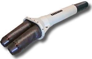
80 UnderSea Repeaters Repeaters use state-of-the-art optical amplifier technology to achieve high performance and reliability in the transmission of multiple wavelength channel signals on multiple fiber pairs which normally use 980nm Pump for boosting up optical signal 96


81 Inside Repeater & different types Amplif ier Pair Chassis Locking Plate Heat Transf er Plate Superv isory Erbium Amplif iers Power Supply Pump Unit Control Circuit 1/2/3/4 up-to 8 Amplifier pairs per Repeater Low/High Gain Repeaters. Low noise & Wide BW Repeaters 980 nm Pumps used in Repeaters. 97
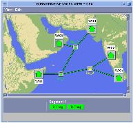
82 Fault localization multi-sidetone line monitoring equipment (MST LME) MST LME is located at cable station. Signal is supplied at two wavelengths (Only one in Svalbard, THz) A change in undersea transmission that might occur during the life of the system is seen as a difference between loop gain measurements made before and after a change has occurred. 98
83 Optical Fault Localization What is a OTDR? Optical Time Domain Reflectometer - also known as an OTDR, is a hardware device used for measurement of the elapsed time and intensity of light reflected on optical fiber. How it works? The reflectometer can compute the distance to problems on the fiber such as attenuation and breaks, making it a useful tool in optical network troubleshooting. The intensity of the return pulses is measured and integrated as a function of time, and is plotted as a function of fiber length. What is a COTDR? Coherent Optical Time Domain Reflectometer - also known as a COTDR, An instrument that is used to perform out of service backscattered light measurements on optically amplified line systems. How it works? A fiber pair is tested by launching a test signal into the out going fiber and receiving the scattered light on the in-coming fiber. Light scattered in the transmission fiber is coupled to the incoming fiber in the loop-back couplers in each amplifier pair in a repeater. 99
84 OTDR Vs COTDR Repeater Repeater Repeater OTDR Light Pulse Backscatter HLLB HLLB HLLB OTDR can only measure upto first repeater Repeater Repeater Repeater Light Pulse COTDR HLLB HLLB HLLB Backscatter COTDR can cross the repeaters & can measure till opposite end terminal 100
85 Remote Optical Pumping Amplifier (ROPA) 19. desember
86 Optical Transport Network
87 Optical Transport Network (OTN): Definition and History Definition Optical networks are comprised of functionality providing transport, multiplexing, switching, supervision and survivability of client signals that are processed predominantly in the photonic domain. Described in the ITU-T Recommendation G.709 (2003), OTN adds operations, administration, maintenance, and provisioning (OAM&P) functionality to optical carriers, specifically in a multi-wavelength system such as dense wavelength division multiplexing (DWDM). The idea: Introduced as Digital Wrapper by Bell-labs in the late 1990s Approval of first version of standard by ITU-T in 2001
88 Why OTN A common way to support transparent transport of any client signals (on DWDM systems) Client signal agnostic Strong Forward Error Correction Monitoring capability for multi domain network services More Levels of Tandem Connection Monitoring (TCM) Switching Scalability

89 ITU-T and OTN work G.709: Interfaces for the optical transport network (OTN) G.798: Functional characteristics of optical networking equipment G.870 contains OTN Terms and Definitions. G.872: Architecture of Optical Transport Networks G.800: Unified Framework for the Architecture of Transport Networks OTN Management: A number or Recs worked out in Q.14/15. G.Sup39: Optical system design and engineering considerations G.959.1: Optical transport networks physical layer interfaces (black link) G.693: Optical interfaces for intra-office systems (up to 2 km) G.694.1: flex grid G.697 Optical monitoring for DWDM systems G.680, G.rmon: OXC, ROADM
90 Pre OTN, DWDM solution Carrier A NE Carrier B Carrier A NE NE NE NE NE Client devices No interopbability between vendors and carriers Signal had to back to client signal level Client devices Vendor proprietary Client signal adaption and transport mechanism
91 Post OTN, DWDM solution Carrier A NE Carrier B Carrier A NE NE NE NE NE Client devices OTN interfaces as common interface Customer devices OTN based Client signal adaption and transport mechanism

92 OTN, Basic functionalities and building blocks
93 Tandem Connection Monitoring (TCM) Though the lightpath is an end-to-end OCh entity, it can be monitored by intermediate systems (e.g. by performing FEC) Signaling is carried by separate fields (TCM) of the ODUk channelassociate overhead 6 levels of TCM are allowed to perform nested, cascaded or overlapping monitoring sessions
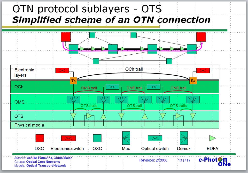
94 Layers in OTN hierarchy Electrical Domain Client signals (e.g. STM-N, IP, Ethernet, OTN ODUk Optical Domain OPU ODU Optical channel Payload Unit Optical channel Data Unit Optical channel Transport Unit Optical channel sublayer (OCh) Optical multiplex section (OMS) Optical transmission section (OTS) FEC OTU OCh OMS OCCoh OTS Mapping of client signals on OPU is going through different mapping procedures. e.g. AMP, BMP, GFP and GMP
95
96 OTN rates and multiplexing Source: Yann Loussouarn, Damien Martinet, Fabrice Herviou, Patrice Robert ( France Telecom Orange Labs)

97 OTN Frame format OCh overhead OCh payload FEC Area Frame rate changes depends on ODUk level, but frame format remains untouched
98 OTN benefits: client signal MUX Unprecedented flexibility in client signal mapping!!!! Higher order and Lower order MUX Phy Flow (VLAN) ODUflex HO ODUk ( ) LO maps non-otn signals of ANY kind HO maps OTN signals Phy Flow (VLAN) ODUflex ODUflex HO ODUk ( ) Designed for data traffic i.e. focus on packet switched clients Phy ODUflex HO ODUk ( ) Advanced MUX paths (extended OTN) Phy ODUj ODU0 (1GE), ODU2e, ODU4 (100 GE) added for extended flexibility Phy HO ODUk ( ) ODUFlex can map ANY bitrate client flow Physical interface Client interface Transport entity full decoupling of client and network PHY Fastest IP over WDM solution IPoOTNoWDM Source: GN3-JRA1-T1

99 one typical Coriant card 19. desember

100 OTN, Switching and traffic grooming
101 ODU switching One possible scenario: - ODU0 switching - Multiplexing / Demultiplexing
102 DWDM OTUk Optical Switch ODU-XC ODU switch OTU-x, GbE, 10GbE, 40GbE, STMxxx, FCx and other type of client signals Clients Separation between wavelength service and sub-wavelength services
103 DWDM OTUk Optical Switch ODU-XC ODU switch OTU-x, GbE, 10GbE, 40GbE, STMxxx, FCx and other type of client signals Clients Integrated wavelength and Sub-wavelength
104 DWDM OTUk Optical Switch ODU-XC ODU switch OTU-x, GbE, 10GbE, 40GbE, STMxxx, FCx and other type of client signals Client Integrated wavelength and Sub-wavelength
105 OTN use scenario (1) Grooming As a grooming device to gather client signals with any different bitrates to a bigger pipe at transport level.


106 Multi-Rate vs. OTN: Comparing Approaches to Build Scalable, Cost-Effective 100Gb/s Networks, ECOC2012 P5.11, Marco Bertolini et al, Grooming at 100G network Comparing pure WDM equipments at both 10Gb/s and 100Gb/s line rate, to a pure100gb/s design where electrical OTN switches are integrated with WDM equipment.
107 OTN Summary OTN is the common layer which stitches together the optical domain with higher order networking layers Advanced AOM&P functionalities (GMPLS-ready) Excellent solution for multi-domain service provisioning OTN became the common interface of choose between different network domain Major vendors already offer advanced OTN functionalities switching and traffic grooming based on OTN will add flexibility without adding another complex network layer Highly scalable, future-proof technology Protection and restoration opportunity on different signal level
108 Backup slides 19. desember
Dr. Monir Hossen ECE, KUET
 Dr. Monir Hossen ECE, KUET 1 Outlines of the Class Principles of WDM DWDM, CWDM, Bidirectional WDM Components of WDM AWG, filter Problems with WDM Four-wave mixing Stimulated Brillouin scattering WDM Network
Qualifying Fiber for 10G Deployment
 Qualifying Fiber for 10G Deployment Presented by: Bob Chomycz, P.Eng. Email: BChomycz@TelecomEngineering.com Tel: 1.888.250.1562 www.telecomengineering.com 2017, Slide 1 of 25 Telecom Engineering Introduction
OPTICAL NETWORKS. Building Blocks. A. Gençata İTÜ, Dept. Computer Engineering 2005
 OPTICAL NETWORKS Building Blocks A. Gençata İTÜ, Dept. Computer Engineering 2005 Introduction An introduction to WDM devices. optical fiber optical couplers optical receivers optical filters optical amplifiers
Advanced Fibre Testing: Paving the Way for High-Speed Networks. Trevor Nord Application Specialist JDSU (UK) Ltd
 Ltd") Advanced Fibre Testing: Paving the Way for High-Speed Networks Trevor Nord Application Specialist JDSU (UK) Ltd Fibre Review Singlemode Optical Fibre Elements of Loss Fibre Attenuation - Caused by scattering
Advanced Fibre Testing: Paving the Way for High-Speed Networks Trevor Nord Application Specialist JDSU (UK) Ltd Fibre Review Singlemode Optical Fibre Elements of Loss Fibre Attenuation - Caused by scattering
DWDM 101 BRKOPT Rodger Nutt High-End Routing and Optical BU Technical Leader
 DWDM 101 Rodger Nutt High-End Routing and Optical BU Technical Leader Agenda Introduction What is DWDM Fiber Types Linear Effects The BIG Three: Attenuation, Chromatic Dispersion, OSNR Solutions to the
DWDM Theory. ZTE Corporation Transmission Course Team. ZTE University
 DWDM Theory ZTE Corporation Transmission Course Team DWDM Overview Multiplexing Technology WDM TDM SDM What is DWDM? Gas Station High Way Prowl Car Definition l 1 l 2 l N l 1 l 2 l 1 l 2 l N OA l N OMU
Optical Transport Technologies and Trends
 Optical Transport Technologies and Trends A Network Planning Perspective Sept 1, 2014 Dion Leung, Director of Solutions and Sales Engineering dleung@btisystem.com About BTI Customers 380+ worldwide in
Elements of Optical Networking
 Bruckner Elements of Optical Networking Basics and practice of optical data communication With 217 Figures, 13 Tables and 93 Exercises Translated by Patricia Joliet VIEWEG+ TEUBNER VII Content Preface
Practical Aspects of Raman Amplifier
 Practical Aspects of Raman Amplifier Contents Introduction Background Information Common Types of Raman Amplifiers Principle Theory of Raman Gain Noise Sources Related Information Introduction This document
Chapter 12: Optical Amplifiers: Erbium Doped Fiber Amplifiers (EDFAs)
") Chapter 12: Optical Amplifiers: Erbium Doped Fiber Amplifiers (EDFAs) Prof. Dr. Yaocheng SHI ( 时尧成 ) yaocheng@zju.edu.cn http://mypage.zju.edu.cn/yaocheng 1 Traditional Optical Communication System Loss
Chapter 12: Optical Amplifiers: Erbium Doped Fiber Amplifiers (EDFAs) Prof. Dr. Yaocheng SHI ( 时尧成 ) yaocheng@zju.edu.cn http://mypage.zju.edu.cn/yaocheng 1 Traditional Optical Communication System Loss
WDM. Coarse WDM. Nortel's WDM System
 WDM wavelength-division multiplexing (WDM) is a technology which multiplexes a number of optical carrier signals onto a single optical fiber by using different wavelengths (i.e. colors) of laser light.
Module 19 : WDM Components
 Module 19 : WDM Components Lecture : WDM Components - I Part - I Objectives In this lecture you will learn the following WDM Components Optical Couplers Optical Amplifiers Multiplexers (MUX) Insertion
Introduction and concepts Types of devices
 ECE 6323 Introduction and concepts Types of devices Passive splitters, combiners, couplers Wavelength-based devices for DWDM Modulator/demodulator (amplitude and phase), compensator (dispersion) Others:
WDM Concept and Components. EE 8114 Course Notes
 WDM Concept and Components EE 8114 Course Notes Part 1: WDM Concept Evolution of the Technology Why WDM? Capacity upgrade of existing fiber networks (without adding fibers) Transparency:Each optical channel
Wavelength Multiplexing. The Target
 The Target Design a MAN* like fiber network for high data transmission rates. The network is partial below sea level and difficult to install and to maintain. Such a fiber network demands an optimized
Optical Transport Tutorial
 Optical Transport Tutorial 4 February 2015 2015 OpticalCloudInfra Proprietary 1 Content Optical Transport Basics Assessment of Optical Communication Quality Bit Error Rate and Q Factor Wavelength Division
Optical networking. Emilie CAMISARD GIP RENATER Optical technologies engineer Advanced IP Services
 Optical networking Emilie CAMISARD GIP RENATER Optical technologies engineer Advanced IP Services Agenda Optical fibre principle Time Division Multiplexing (TDM) Wavelength Division Multiplexing (WDM)
Cisco s CLEC Networkers Power Session
 Course Number Presentation_ID 1 Cisco s CLEC Networkers Power Session Session 2 The Business Case for ONS 15800 3 What s Driving the Demand? Data Voice 4 What s Driving the Demand? Internet 36,700,000
Optical Communications and Networking 朱祖勍. Sept. 25, 2017
 Optical Communications and Networking Sept. 25, 2017 Lecture 4: Signal Propagation in Fiber 1 Nonlinear Effects The assumption of linearity may not always be valid. Nonlinear effects are all related to
Introduction Fundamental of optical amplifiers Types of optical amplifiers
 ECE 6323 Introduction Fundamental of optical amplifiers Types of optical amplifiers Erbium-doped fiber amplifiers Semiconductor optical amplifier Others: stimulated Raman, optical parametric Advanced application:
Fundamentals of DWDM Technology
 CHAPTER 2 The emergence of DWDM is one of the most recent and important phenomena in the development of fiber optic transmission technology. In the following discussion we briefly trace the stages of fiber
Total care for networks. Introduction to Dispersion
 Introduction to Dispersion Introduction to PMD Version1.0- June 01, 2000 Copyright GN Nettest 2000 Introduction To Dispersion Contents Definition of Dispersion Chromatic Dispersion Polarization Mode Dispersion
Optical Communications and Networks - Review and Evolution (OPTI 500) Massoud Karbassian
 Massoud Karbassian") Optical Communications and Networks - Review and Evolution (OPTI 500) Massoud Karbassian m.karbassian@arizona.edu Contents Optical Communications: Review Optical Communications and Photonics Why Photonics?
Optical Communications and Networks - Review and Evolution (OPTI 500) Massoud Karbassian m.karbassian@arizona.edu Contents Optical Communications: Review Optical Communications and Photonics Why Photonics?
Thursday, April 17, 2008, 6:28:40
 Wavelength Division Multiplexing By: Gurudatha Pai K gurudatha@gmail.com Thursday, April 17, 2008, 6:28:40 Overview Introduction Popular Multiplexing Techniques Optical Networking WDM An Analogy of Multiplexing
Optical Amplifiers Photonics and Integrated Optics (ELEC-E3240) Zhipei Sun Photonics Group Department of Micro- and Nanosciences Aalto University
 Zhipei Sun Photonics Group Department of Micro- and Nanosciences Aalto University") Photonics Group Department of Micro- and Nanosciences Aalto University Optical Amplifiers Photonics and Integrated Optics (ELEC-E3240) Zhipei Sun Last Lecture Topics Course introduction Ray optics & optical
Photonics Group Department of Micro- and Nanosciences Aalto University Optical Amplifiers Photonics and Integrated Optics (ELEC-E3240) Zhipei Sun Last Lecture Topics Course introduction Ray optics & optical
Module 19 : WDM Components
 Module 19 : WDM Components Lecture : WDM Components - II Objectives In this lecture you will learn the following OADM Optical Circulators Bidirectional OADM using Optical Circulators and FBG Optical Cross
Optical Fibre Amplifiers Continued
 1 Optical Fibre Amplifiers Continued Stavros Iezekiel Department of Electrical and Computer Engineering University of Cyprus ECE 445 Lecture 09 Fall Semester 2016 2 ERBIUM-DOPED FIBRE AMPLIFIERS BASIC
Rogério Nogueira Instituto de Telecomunicações Pólo de Aveiro Departamento de Física Universidade de Aveiro
 Fiber Bragg Gratings for DWDM Optical Networks Rogério Nogueira Instituto de Telecomunicações Pólo de Aveiro Departamento de Física Universidade de Aveiro Overview Introduction. Fabrication. Physical properties.
OPTICAL COMMUNICATIONS S
 OPTICAL COMMUNICATIONS S-108.3110 1 Course program 1. Introduction and Optical Fibers 2. Nonlinear Effects in Optical Fibers 3. Fiber-Optic Components 4. Transmitters and Receivers 5. Fiber-Optic Measurements
Chapter 8. Wavelength-Division Multiplexing (WDM) Part II: Amplifiers
 Part II: Amplifiers") Chapter 8 Wavelength-Division Multiplexing (WDM) Part II: Amplifiers Introduction Traditionally, when setting up an optical link, one formulates a power budget and adds repeaters when the path loss exceeds
Chapter 8 Wavelength-Division Multiplexing (WDM) Part II: Amplifiers Introduction Traditionally, when setting up an optical link, one formulates a power budget and adds repeaters when the path loss exceeds
Network Challenges for Coherent Systems. Mike Harrop Technical Sales Engineering, EXFO
 Network Challenges for Coherent Systems Mike Harrop Technical Sales Engineering, EXFO Agenda 1. 100G Transmission Technology 2. Non Linear effects 3. RAMAN Amplification 1. Optimsing gain 2. Keeping It
Exam : : Cisco Optical SONET Exam. Title. Ver :
 Exam : 642-311 Title : Cisco Optical SONET Exam Ver : 10.05.07 QUESTION 1: The exhibit shows a 15454/15216 DWDM system and alarm indications. What are two possible sources of trouble shown in the system?
Pass Cisco Exam
 Pass Cisco 642-321 Exam Number: 642-321 Passing Score: 800 Time Limit: 120 min File Version: 38.8 http://www.gratisexam.com/ Pass Cisco 642-321 Exam Exam Name : Cisco Optical SDH Exam (SDH) Braindumps
Mixing TrueWave RS Fiber with Other Single-Mode Fiber Designs Within a Network
 Mixing TrueWave RS Fiber with Other Single-Mode Fiber Designs Within a Network INTRODUCTION A variety of single-mode fiber types can be found in today s installed networks. Standards bodies, such as the
Signal Conditioning Parameters for OOFDM System
 Chapter 4 Signal Conditioning Parameters for OOFDM System 4.1 Introduction The idea of SDR has been proposed for wireless transmission in 1980. Instead of relying on dedicated hardware, the network has
Dispersion in Optical Fibers
 Dispersion in Optical Fibers By Gildas Chauvel Anritsu Corporation TABLE OF CONTENTS Introduction Chromatic Dispersion (CD): Definition and Origin; Limit and Compensation; and Measurement Methods Polarization
Current Trends in Unrepeatered Systems
 Current Trends in Unrepeatered Systems Wayne Pelouch (Xtera, Inc.) Email: wayne.pelouch@xtera.com Xtera, Inc. 500 W. Bethany Drive, suite 100, Allen, TX 75013, USA. Abstract: The current trends in unrepeatered
AC : FIBER OPTICS COURSE FOR UNDERGRADUATE ELECTRICAL ENGINEERING STUDENTS
 AC 2009-385: FIBER OPTICS COURSE FOR UNDERGRADUATE ELECTRICAL ENGINEERING STUDENTS Lihong (Heidi) Jiao, Grand Valley State University American Society for Engineering Education, 2009 Page 14.630.1 Fiber
Introduction to BER testing of WDM systems
 Introduction to BER testing of WDM systems Application note 1299 Wavelength division multiplexing (WDM) is a new and exciting technology for migrating the core optical transmission network to higher bandwidths.
CWDM Cisco CWDM wavelengths (nm)
") Cisco Enhanced Wavelength Division Multiplexing Product Line The Cisco enhanced wavelength-division multiplexing (EWDM) product line allows users to scale the speed and capacity of the services offered
Cisco Enhanced Wavelength Division Multiplexing Product Line The Cisco enhanced wavelength-division multiplexing (EWDM) product line allows users to scale the speed and capacity of the services offered
S Optical Networks Course Lecture 4: Transmission System Engineering
 S-72.3340 Optical Networks Course Lecture 4: Transmission System Engineering Edward Mutafungwa Communications Laboratory, Helsinki University of Technology, P. O. Box 2300, FIN-02015 TKK, Finland Tel:
Performance Analysis of Designing a Hybrid Optical Amplifier (HOA) for 32 DWDM Channels in L-band by using EDFA and Raman Amplifier
 for 32 DWDM Channels in L-band by using EDFA and Raman Amplifier") Performance Analysis of Designing a Hybrid Optical Amplifier (HOA) for 32 DWDM Channels in L-band by using EDFA and Raman Amplifier Aied K. Mohammed, PhD Department of Electrical Engineering, University
Performance Analysis of Designing a Hybrid Optical Amplifier (HOA) for 32 DWDM Channels in L-band by using EDFA and Raman Amplifier Aied K. Mohammed, PhD Department of Electrical Engineering, University
WDM in backbone. Péter Barta Alcatel-Lucent
 WDM in backbone Péter Barta Alcatel-Lucent 10. October 2012 AGENDA 1. ROADM solutions 2. 40G, 100G, 400G 2 1. ROADM solutions 3 Ch 1-8 Ch 9-16 Ch 25-32 Ch 17-24 ROADM solutions What to achieve? Typical
RZ BASED DISPERSION COMPENSATION TECHNIQUE IN DWDM SYSTEM FOR BROADBAND SPECTRUM
 RZ BASED DISPERSION COMPENSATION TECHNIQUE IN DWDM SYSTEM FOR BROADBAND SPECTRUM Prof. Muthumani 1, Mr. Ayyanar 2 1 Professor and HOD, 2 UG Student, Department of Electronics and Communication Engineering,
LW Technology. Passive Components. LW Technology (Passive Components).PPT - 1 Copyright 1999, Agilent Technologies
.PPT - 1 Copyright 1999, Agilent Technologies") LW Technology Passive Components LW Technology (Passive Components).PPT - 1 Patchcords Jumper cables to connect devices and instruments Adapter cables to connect interfaces using different connector styles
LW Technology Passive Components LW Technology (Passive Components).PPT - 1 Patchcords Jumper cables to connect devices and instruments Adapter cables to connect interfaces using different connector styles
Technical Feasibility of 4x25 Gb/s PMD for 40km at 1310nm using SOAs
 Technical Feasibility of 4x25 Gb/s PMD for 40km at 1310nm using SOAs Ramón Gutiérrez-Castrejón RGutierrezC@ii.unam.mx Tel. +52 55 5623 3600 x8824 Universidad Nacional Autonoma de Mexico Introduction A
Optical Communications and Networking 朱祖勍. Oct. 9, 2017
 Optical Communications and Networking Oct. 9, 2017 1 Optical Amplifiers In optical communication systems, the optical signal from the transmitter are attenuated by the fiber and other passive components
Optinex. Alcatel 1686 WM. 32 Channels DWDM System (Regional & Metro)
") Optinex Alcatel 1686 WM 32 Channels DWDM System (Regional & Metro) Compliant with G.692 ITU-T standards. Product based on flat gain amplifiers and dense wavelength division multiplexers. Designed for very
Optinex Alcatel 1686 WM 32 Channels DWDM System (Regional & Metro) Compliant with G.692 ITU-T standards. Product based on flat gain amplifiers and dense wavelength division multiplexers. Designed for very
OFC SYSTEMS Performance & Simulations. BC Choudhary NITTTR, Sector 26, Chandigarh
 OFC SYSTEMS Performance & Simulations BC Choudhary NITTTR, Sector 26, Chandigarh High Capacity DWDM OFC Link Capacity of carrying enormous rates of information in THz 1.1 Tb/s over 150 km ; 55 wavelengths
UNIT - 7 WDM CONCEPTS AND COMPONENTS
 UNIT - 7 WDM CONCEPTS AND COMPONENTS WDM concepts, overview of WDM operation principles, WDM standards, Mach-Zehender interferometer, multiplexer, Isolators and circulators, direct thin film filters, active
40Gb/s Coherent DP-PSK for Submarine Applications
 4Gb/s Coherent DP-PSK for Submarine Applications Jamie Gaudette, Elizabeth Rivera Hartling, Mark Hinds, John Sitch, Robert Hadaway Email: Nortel, 3 Carling Ave., Ottawa, ON, Canada
Contents for this Presentation. Multi-Service Transport
 Contents for this Presentation SDH/DWDM based Multi-Service Transport Platform by Khurram Shahzad ad Brief Contents Description for this of Presentation the Project Development of a Unified Transport Platform
ITU-T G (11/2009) Multichannel DWDM applications with single-channel optical interfaces
 Multichannel DWDM applications with single-channel optical interfaces") International Telecommunication Union ITU-T TELECOMMUNICATION STANDARDIZATION SECTOR OF ITU G.698.1 (11/2009) SERIES G: TRANSMISSION SYSTEMS AND MEDIA, DIGITAL SYSTEMS AND NETWORKS Transmission media and
International Telecommunication Union ITU-T TELECOMMUNICATION STANDARDIZATION SECTOR OF ITU G.698.1 (11/2009) SERIES G: TRANSMISSION SYSTEMS AND MEDIA, DIGITAL SYSTEMS AND NETWORKS Transmission media and
Chirped Bragg Grating Dispersion Compensation in Dense Wavelength Division Multiplexing Optical Long-Haul Networks
 363 Chirped Bragg Grating Dispersion Compensation in Dense Wavelength Division Multiplexing Optical Long-Haul Networks CHAOUI Fahd 3, HAJAJI Anas 1, AGHZOUT Otman 2,4, CHAKKOUR Mounia 3, EL YAKHLOUFI Mounir
MAHALAKSHMI ENGINEERING COLLEGE TIRUCHIRAPALLI
 MAHALAKSHMI ENGINEERING COLLEGE TIRUCHIRAPALLI - 621213 DEPARTMENT : ECE SUBJECT NAME : OPTICAL COMMUNICATION & NETWORKS SUBJECT CODE : EC 2402 1. Define SONET/SDH. [AUC NOV 2007] UNIT V: OPTICAL NETWORKS
E2-E3 CONSUMER FIXED ACCESS. CHAPTER-4 OVERVIEW OF OFC NETWORK (Date Of Creation: )
") E2-E3 CONSUMER FIXED ACCESS CHAPTER-4 OVERVIEW OF OFC NETWORK (Date Of Creation: 01-04-2011) Page: 1 Overview Of OFC Network Learning Objective: Optical Fiber concept & types OFC route and optical budget
E2-E3 CONSUMER FIXED ACCESS CHAPTER-4 OVERVIEW OF OFC NETWORK (Date Of Creation: 01-04-2011) Page: 1 Overview Of OFC Network Learning Objective: Optical Fiber concept & types OFC route and optical budget
The absorption of the light may be intrinsic or extrinsic
 Attenuation Fiber Attenuation Types 1- Material Absorption losses 2- Intrinsic Absorption 3- Extrinsic Absorption 4- Scattering losses (Linear and nonlinear) 5- Bending Losses (Micro & Macro) Material
Performance Limitations of WDM Optical Transmission System Due to Cross-Phase Modulation in Presence of Chromatic Dispersion
 Performance Limitations of WDM Optical Transmission System Due to Cross-Phase Modulation in Presence of Chromatic Dispersion M. A. Khayer Azad and M. S. Islam Institute of Information and Communication
Optical Communications and Networks - Review and Evolution (OPTI 500) Massoud Karbassian
 Massoud Karbassian") Optical Communications and Networks - Review and Evolution (OPTI 500) Massoud Karbassian m.karbassian@arizona.edu Contents Optical Communications: Review Optical Communications and Photonics Why Photonics?
Optical Communications and Networks - Review and Evolution (OPTI 500) Massoud Karbassian m.karbassian@arizona.edu Contents Optical Communications: Review Optical Communications and Photonics Why Photonics?
FIBER OPTICS. Prof. R.K. Shevgaonkar. Department of Electrical Engineering. Indian Institute of Technology, Bombay. Lecture: 26
 FIBER OPTICS Prof. R.K. Shevgaonkar Department of Electrical Engineering Indian Institute of Technology, Bombay Lecture: 26 Wavelength Division Multiplexed (WDM) Systems Fiber Optics, Prof. R.K. Shevgaonkar,
S Optical Networks Course Lecture 2: Essential Building Blocks
 S-72.3340 Optical Networks Course Lecture 2: Essential Building Blocks Edward Mutafungwa Communications Laboratory, Helsinki University of Technology, P. O. Box 2300, FIN-02015 TKK, Finland Tel: +358 9
ITU-T G (07/2007) Amplified multichannel DWDM applications with single channel optical interfaces
 Amplified multichannel DWDM applications with single channel optical interfaces") International Telecommunication Union ITU-T TELECOMMUNICATION STANDARDIZATION SECTOR OF ITU G.698.2 (07/2007) SERIES G: TRANSMISSION SYSTEMS AND MEDIA, DIGITAL SYSTEMS AND NETWORKS Transmission media and
International Telecommunication Union ITU-T TELECOMMUNICATION STANDARDIZATION SECTOR OF ITU G.698.2 (07/2007) SERIES G: TRANSMISSION SYSTEMS AND MEDIA, DIGITAL SYSTEMS AND NETWORKS Transmission media and
Optical Add-Drop Multiplexer Based on Fiber Bragg Gratings for Dense Wavelength Division Multiplexing Networks
 Optical Add-Drop Multiplexer Based on Fiber Bragg Gratings for Dense Wavelength Division Multiplexing Networks P. S. André 1, 2, A. Nolasco Pinto 1, 3, J. L. Pinto 1, 2, T. Almeida 1, 4 and M. Pousa 1,4
Design and optimization of WDM PON system using Spectrum Sliced Technique
 Design and optimization of WDM PON system using Spectrum Sliced Technique Sukhwinder Kaur 1, Neena Gupta 2 P.G. Student, Department of Electronics and Communication Engineering, PEC University of Technology,
40Gb/s Optical Transmission System Testbed
 The University of Kansas Technical Report 40Gb/s Optical Transmission System Testbed Ron Hui, Sen Zhang, Ashvini Ganesh, Chris Allen and Ken Demarest ITTC-FY2004-TR-22738-01 January 2004 Sponsor: Sprint
Optical communications
 Optical communications Components and enabling technologies Optical networking Evolution of optical networking: road map SDH = Synchronous Digital Hierarchy SONET = Synchronous Optical Network SDH SONET
Wavelength-Enhanced Passive Optical Networks with Extended Reach
 Wavelength-Enhanced Passive Optical Networks with Extended Reach Ken Reichmann and Pat Iannone Optical Systems Research AT&T Labs, Middletown NJ Thanks to Han Hyub Lee, Xiang Zhou, and Pete Magill Wavelength-Enhanced
Multichannel DWDM applications with single channel optical interfaces for repeaterless optical fibre submarine cable systems
 International Telecommunication Union ITU-T TELECOMMUNICATION STANDARDIZATION SECTOR OF ITU G.973.2 (04/2011) SERIES G: TRANSMISSION SYSTEMS AND MEDIA, DIGITAL SYSTEMS AND NETWORKS Digital sections and
Advanced Optical Communications Prof. R. K. Shevgaonkar Department of Electrical Engineering Indian Institute of Technology, Bombay
 Advanced Optical Communications Prof. R. K. Shevgaonkar Department of Electrical Engineering Indian Institute of Technology, Bombay Lecture No. # 27 EDFA In the last lecture, we talked about wavelength
ADVANCED OPTICAL FIBER FOR LONG DISTANCE TELECOMMUNICATION NETWORKS
 Presented at AMTC 2000 ADVANCED OPTICAL FIBER FOR LONG DISTANCE TELECOMMUNICATION NETWORKS Christopher Towery North American Market Development Manager towerycr@corning.com & E. Alan Dowdell European Market
PERFORMANCE ANALYSIS OF WDM AND EDFA IN C-BAND FOR OPTICAL COMMUNICATION SYSTEM
 www.arpapress.com/volumes/vol13issue1/ijrras_13_1_26.pdf PERFORMANCE ANALYSIS OF WDM AND EDFA IN C-BAND FOR OPTICAL COMMUNICATION SYSTEM M.M. Ismail, M.A. Othman, H.A. Sulaiman, M.H. Misran & M.A. Meor
Emerging Subsea Networks
 Optimization of Pulse Shaping Scheme and Multiplexing/Demultiplexing Configuration for Ultra-Dense WDM based on mqam Modulation Format Takanori Inoue, Yoshihisa Inada, Eduardo Mateo, Takaaki Ogata (NEC
Optical Measurements in 100 and 400 Gb/s Networks: Will Coherent Receivers Take Over? Fred Heismann
 Optical Measurements in 100 and 400 Gb/s Networks: Will Coherent Receivers Take Over? Fred Heismann Chief Scientist Fiberoptic Test & Measurement Key Trends in DWDM and Impact on Test & Measurement Complex
Photonics (OPTI 510R 2017) - Final exam. (May 8, 10:30am-12:30pm, R307)
 - Final exam. (May 8, 10:30am-12:30pm, R307)") Photonics (OPTI 510R 2017) - Final exam (May 8, 10:30am-12:30pm, R307) Problem 1: (30pts) You are tasked with building a high speed fiber communication link between San Francisco and Tokyo (Japan) which
Photonics (OPTI 510R 2017) - Final exam (May 8, 10:30am-12:30pm, R307) Problem 1: (30pts) You are tasked with building a high speed fiber communication link between San Francisco and Tokyo (Japan) which
Emerging Subsea Networks
 Upgrading on the Longest Legacy Repeatered System with 100G DC-PDM- BPSK Jianping Li, Jiang Lin, Yanpu Wang (Huawei Marine Networks Co. Ltd) Email: Huawei Building, No.3 Shangdi
UNIT - 7 WDM CONCEPTS AND COMPONENTS
 UNIT - 7 LECTURE-1 WDM CONCEPTS AND COMPONENTS WDM concepts, overview of WDM operation principles, WDM standards, Mach-Zehender interferometer, multiplexer, Isolators and circulators, direct thin film
UNREPEATERED SYSTEMS: STATE OF THE ART CAPABILITY
 UNREPEATERED SYSTEMS: STATE OF THE ART CAPABILITY Nicolas Tranvouez, Eric Brandon, Marc Fullenbaum, Philippe Bousselet, Isabelle Brylski Nicolas.tranvouez@alcaltel.lucent.fr Alcatel-Lucent, Centre de Villarceaux,
There are lots of problems or challenges with fiber, Attenuation, Reflections, Dispersion and so on. So here we will look at these problems.
 The Hard theory The Hard Theory An introduction to fiber, should also include a section with some of the difficult theory. So if everything else in the book was very easily understood, then this section
Design of an Optical Submarine Network With Longer Range And Higher Bandwidth
 Design of an Optical Submarine Network With Longer Range And Higher Bandwidth Yashas Joshi 1, Smridh Malhotra 2 1,2School of Electronics Engineering (SENSE) Vellore Institute of Technology Vellore, India
UNREPEATERED SYSTEMS: STATE OF THE ART
 UNREPEATERED SYSTEMS: STATE OF THE ART Hans Bissessur, Isabelle Brylski, Dominique Mongardien (Alcatel-Lucent Submarine Networks), Philippe Bousselet (Alcatel-Lucent Bell Labs) Email: < hans.bissessur@alcatel-lucent.com
from ocean to cloud Power budget line parameters evaluation on a system having reached its maximum capacity
 Power budget line parameters evaluation on a system having reached its maximum capacity Marc-Richard Fortin, Antonio Castruita, Luiz Mario Alonso Email: marc.fortin@globenet.net Brasil Telecom of America
Fiber Bragg Grating Dispersion Compensation Enables Cost-Efficient Submarine Optical Transport
 Fiber Bragg Grating Dispersion Compensation Enables Cost-Efficient Submarine Optical Transport By Fredrik Sjostrom, Proximion Fiber Systems Undersea optical transport is an important part of the infrastructure
Emerging Subsea Networks
 EVALUATION OF NONLINEAR IMPAIRMENT FROM NARROW- BAND UNPOLARIZED IDLERS IN COHERENT TRANSMISSION ON DISPERSION-MANAGED SUBMARINE CABLE SYSTEMS Masashi Binkai, Keisuke Matsuda, Tsuyoshi Yoshida, Naoki Suzuki,
Ultra-long Span Repeaterless Transmission System Technologies
 Ultra-long Span Repeaterless Transmission System Technologies INADA Yoshihisa Abstract The recent increased traffic accompanying the rapid dissemination of broadband communications has been increasing
Optical Fiber Attributes
 Optical Fiber Attributes What Matters As Capacity Demands Increase And Networks Evolve Ian Davis Regional Marketing Manager, EMEA and Strategic Alliances Manager Agenda What attributes matter in long-haul,
Performance Evaluation of 32 Channel DWDM System Using Dispersion Compensation Unit at Different Bit Rates
 Performance Evaluation of 32 Channel DWDM System Using Dispersion Compensation Unit at Different Bit Rates Simarpreet Kaur Gill 1, Gurinder Kaur 2 1Mtech Student, ECE Department, Rayat- Bahra University,
Optical Fibers p. 1 Basic Concepts p. 1 Step-Index Fibers p. 2 Graded-Index Fibers p. 4 Design and Fabrication p. 6 Silica Fibers p.
 Preface p. xiii Optical Fibers p. 1 Basic Concepts p. 1 Step-Index Fibers p. 2 Graded-Index Fibers p. 4 Design and Fabrication p. 6 Silica Fibers p. 6 Plastic Optical Fibers p. 9 Microstructure Optical
Setup of the four-wavelength Doppler lidar system with feedback controlled pulse shaping
 Setup of the four-wavelength Doppler lidar system with feedback controlled pulse shaping Albert Töws and Alfred Kurtz Cologne University of Applied Sciences Steinmüllerallee 1, 51643 Gummersbach, Germany
Performance Analysis of 48 Channels DWDM System using EDFA for Long Distance Communication
 GRD Journals- Global Research and Development Journal for Engineering Volume 2 Issue 3 February 2017 ISSN: 2455-5703 Performance Analysis of 48 Channels DWDM System using EDFA for Long Distance Communication
CHAPTER 5 SPECTRAL EFFICIENCY IN DWDM
 61 CHAPTER 5 SPECTRAL EFFICIENCY IN DWDM 5.1 SPECTRAL EFFICIENCY IN DWDM Due to the ever-expanding Internet data traffic, telecommunication networks are witnessing a demand for high-speed data transfer.
EE 233. LIGHTWAVE. Chapter 2. Optical Fibers. Instructor: Ivan P. Kaminow
 EE 233. LIGHTWAVE SYSTEMS Chapter 2. Optical Fibers Instructor: Ivan P. Kaminow PLANAR WAVEGUIDE (RAY PICTURE) Agrawal (2004) Kogelnik PLANAR WAVEGUIDE a = (n s 2 - n c2 )/ (n f 2 - n s2 ) = asymmetry;
PERFORMANCE ANALYSIS OF OPTICAL TRANSMISSION SYSTEM USING FBG AND BESSEL FILTERS
 PERFORMANCE ANALYSIS OF OPTICAL TRANSMISSION SYSTEM USING FBG AND BESSEL FILTERS Antony J. S., Jacob Stephen and Aarthi G. ECE Department, School of Electronics Engineering, VIT University, Vellore, Tamil
Computer Networks
 15-441 Computer Networks Physical Layer Professor Hui Zhang hzhang@cs.cmu.edu 1 Communication & Physical Medium There were communications before computers There were communication networks before computer
EDFA Applications in Test & Measurement
 EDFA Applications in Test & Measurement White Paper PN 200-0600-00 Revision 1.1 September 2003 Calmar Optcom, Inc www.calamropt.com Overview Erbium doped fiber amplifiers (EDFAs) amplify optical pulses
Suppression of Stimulated Brillouin Scattering
 Suppression of Stimulated Brillouin Scattering 42 2 5 W i de l y T u n a b l e L a s e r T ra n s m i t te r www.lumentum.com Technical Note Introduction This technical note discusses the phenomenon and
Preparatory School to the Winter College on Fibre Optics, Fibre Lasers and Sensors
 SMR 1826-9 Preparatory School to the Winter College on Fibre Optics, Fibre Lasers and Sensors 5-9 February 2007 Fiber-Optic Communications Hugo L. Fragnito Optics and Photonics Research Center UNICAMP-IFGW
Dynamic gain-tilt compensation using electronic variable optical attenuators and a thin film filter spectral tilt monitor
 Dynamic gain-tilt compensation using electronic variable optical attenuators and a thin film filter spectral tilt monitor P. S. Chan, C. Y. Chow, and H. K. Tsang Department of Electronic Engineering, The
SYLLABUS Optical Fiber Communication
 SYLLABUS Optical Fiber Communication Subject Code : IA Marks : 25 No. of Lecture Hrs/Week : 04 Exam Hours : 03 Total no. of Lecture Hrs. : 52 Exam Marks : 100 UNIT - 1 PART - A OVERVIEW OF OPTICAL FIBER
ITU-T G.695. Optical interfaces for coarse wavelength division multiplexing applications
 International Telecommunication Union ITU-T G.695 TELECOMMUNICATION STANDARDIZATION SECTOR OF ITU (10/2010) SERIES G: TRANSMISSION SYSTEMS AND MEDIA, DIGITAL SYSTEMS AND NETWORKS Transmission media and
Study and Simulation of Dispersion Compensation Scheme Effects on the Performance of Optical WDM System
 People s Democratic Republic of Algeria Ministry of Higher Education and Scientific Research University M Hamed BOUGARA Boumerdes Institute of Electrical and Electronic Engineering Department of Electronics