THE McINTOSH MR 78 SOLID STATE FM/FM STEREO TUNER
|
|
|
- Darren Lynch
- 6 years ago
- Views:
Transcription


1 THE McINTOSH MR 78 SOLID STATE FM/FM STEREO TUNER Reading Time 32 Minutes Price $1.25
2
3 Your MR 78 FM/FM Stereo Tuner will give you many years of pleasant and satisfactory performance. If you have any questions concerning the operation or maintenance of this instrument, please contact: CUSTOMER SERVICE Mclntosh Laboratory Inc. 2 Chambers Street Binghamton, New York Phone: Take Advantage of 3 years of FREE Factory Service... Fill in the Application NOW. CONTENTS GUARANTEE 1 INSTALLATION 2,3 HOW TO CONNECT 4,5 BACK PANEL INFORMATION 6 FRONT PANEL INFORMATION 6,7 LISTENING TO THE MR 78 TUNER 8 PERFORMANCE LIMITS 9 TYPICAL PERFORMANCE CHARTS 10,11 TECHNICAL DESCRIPTION 12,13,14 BLOCK DIAGRAM 15,16 Mclntosh Laboratory Incorporated guarantees this Instrument to be capable of performance as advertised. We also guarantee the mechanical and electrical workmanship and components to be free of defects for a period of 90 days from date of purchase. If such defects occur, Mclntosh Laboratory GUARANTEE or one of its authorized agencies will repair the defect at no cost to the purchaser. This guarantee does not extend to components damaged by improper use nor does it extend to transportation to and from the factory or service agency. THREE YEAR FACTORY SERVICE CONTRACT An application for a FREE THREE YEAR FACTORY SERVICE CONTRACT is included with this manual. The terms of the contract are: 1. Mclntosh will provide all parts, materials and labor needed to return the measured performance of the instrument to the original performance limits free of any charge. The SERVICE CON- TRACT does not cover any shipping costs to and from the authorized service agency or the factory. 2. Any Mclntosh authorized service agency will repair all Mclntosh instruments at normal service rates. To receive the free service under the terms of the SERVICE CONTRACT, the SERVICE CON- TRACT CERTIFICATE must accompany the instrument when taken to the service agency. 3. Always have service done by a Mclntosh authorized service agency. If the instrument is modified or damaged, as a result of unauthorized repair the SERVICE CONTRACT will be cancelled. Damage by improper use or mishandling is not covered by the SERVICE CONTRACT. 4. The SERVICE CONTRACT is issued to you as the original purchaser. To protect you from misrepresentation this contract cannot be transferred to a second owner. 5. The SERVICE CONTRACT is given to purchasers who live In the 50 United States or Canada only. 6. For your protection Mclntosh selects Its dealers carefully. Only one dealer in ten qualifies for a Mclntosh franchise. To receive the SERVICE CONTRACT your purchase must be made from a Mclntosh franchised dealer. 7. Your completely filled in application for a SERV- ICE CONTRACT must be postmarked within 30 days of the date of purchase of the instrument. 8. To receive the SERVICE CONTRACT all information on the application must be filled in. The SERVICE CONTRACT will be issued when the completely filled in application is received at Mclntosh Laboratory Incorporated In Binghamton, New York. If the application is not received at Mclntosh Laboratory, only the service offered under the 90-day guarantee will apply. Copyright 1972 By Mclntosh Laboratory Inc. 1


4 It is recommended that the MR 78 tuner be mounted in a normal or horizontal position. However, with adequate ventilation the tuner can be mounted in any position. Adequate ventilation extends the trouble-free life of electronic instruments. It is generally found that each 18 F rise in operating temperature reduces the life of electrical insulation by one half. Adequate ventilation is an inexpensive and effective means of preventing insulation breakdown that results from unnecessarily high operating temperatures. The direct benefit of adequate ventilation is longer, troublefree life. The MR 78 tuner requires a mounting space that is at least 15 inches deep, 17½ inches wide and 6 inches high. Provide additional space for the air flow across the bottom of the tuner and a means for warm air to escape at the top. Remove the tuner, shelf brackets, parts bag and the mounting template from the carton. Remove tuner from the plastic bag and place the tuner upside down on the shipping pallet, then remove the four plastic feet fastened to the bottom of the chassis. The installation may be accomplished in six easy steps. 1. POSITION TEMPLATE AND MARK Position the plastic mounting template over the area of the cabinet panel where the MR 78 is to be installed. Be sure that the edges of the template 2 clear any shelves, partitions or existing equipment located behind the panel. With the template in place mark the six "A" and "B" holes and four small holes locating the corners of the cutout. Next, join the four corner marks with pencil lines; the edge of the template may be used as a straight edge. 2. DRILL HOLES Holding a drill perpendicularly to the panel, drill the six "A" and "B" holes using a 3/16 inch drill. THE SIX HOLES MUST BE DRILLED BEFORE MAKING THE CUTOUT. 3. SAW CUTOUT Using a saw carefully cut the rectangular opening on the inside of the pencilled rectangle. 4. SECURE MOUNTING STRIPS Secure mounting strips (supplied in the hardware package) on the inside of the cabinet panel. Insert two screws (supplied in the hardware package) into the center holes ("B" holes on the template). Use the ¾-inch long screws for panels under ½-inch or 1¼-inch screws for panels ½-inch thick or over. Place a mounting strip on the back of the cabinet panel as shown. Align it with the three holes in the panel and tighten the screw. The screw head should pull slightly into the wood panel. Attach the other mounting strip by repeating the procedure. 5. MOUNT PANLOC SHELF BRACKETS Attach the Panloc shelf brackets to the cabinet panel using four screws of the proper length. Place the template over the mounting screws. The screws should be centered on the "A" and "B" holes in the template. If necessary, loosen the screws and push the mounting brackets into alignment then retighten. 6. INSTALL THE UNIT Thread the power cord through the opening on the cabinet panel. Carefully slide the instrument into the opening so the rails on the bottom engage the

 will release the instrument.")
5 track on the mounting brackets. Slide the instrument in until it stops at the adjust position latches. Press the latches in and continue to slide the instrument until its front panel is flush with the cabinet panel. At the bottom front corners of the instrument are the PANLOC buttons. Depressing the PANLOC buttons will lock the instrument firmily in the cabinet. Depressing the PANLOC buttons a second time {as with a ballpoint pen) will release the instrument. You can then slide the instrument forward to the adjust position. Depressing the adjust position latches will allow the instrument to be removed from the cabinet. 3


6 How to Connect AUDIO OUTPUTS Use the FIXED OUTPUT jacks to connect to a stereo control preamplifier or other equipment which has its own volume control. The VOLUME CONTROL does not affect the output of the tuner at the FIXED OUT- PUT jacks. The output impedance at the FIXED OUTPUTS is 600 ohms. Longer cables than are normally supplied can be used to interconnect the MR 78 with other equipment. The length of the cable is limited by the capacity of the cable. The total capacity must not exceed 1600 pf. For instance: cables with a capacity of 32 pf per foot may be 50 feet long; 16 pf per foot cable may be 100 feet long. Use the FRONT PANEL CONTROLLED jacks to connect to equipment such as power amplifiers or tape recorders where control of volume at the tuner is desired. The load impedance connected to the FRONT PANEL CONTROLLED jacks should not be less than 47,000 ohms. There is no difference in the signal quality or maximum output levels available at either pair of output jacks. CONNECTING AN FM ANTENNA One of three antenna systems can be used: (1) an outdoor FM antenna, (2) an all channel (UHF-VHF-FM) antenna, or (3) the indoor dipole supplied with the MR 78. An outdoor antenna is recommended for optimum performance in all areas. In fringe (outlying) areas, best results will be obtained with a highly directional FM antenna used in conjunction with a rotator. Rotate the antenna until the best reception is obtained. Connect the 300 ohm antenna to the 300 ANT (red) terminals. A UHF-VHF-FM antenna is often effective but the antenna must be designed for both FM and TV reception. Connect the leads from the UHF-VHF-TV antenna to the 300 ANT (red) terminals. CONNECTING AN INDOOR DIPOLE ANTENNA The flexible folded dipole antenna (300 ohm) is for use in urban or high strength signal areas. Connect the two leads from the dipole to the 300 ANT (red) terminals. The flexibility of the thin flat wire assembly permits it to be placed under a rug, tacked behind the stereo... or, placed in any other convenient location. In some cases, it may be necessary to "position" the antenna for best signal reception. This should be done before it is permanently located. Avoid locating this antenna next to other wires or metal objects. This antenna may not prove effective in houses having metal siding or metal-clad insulation. CONNECTING A 75 OHM ANTENNA An unbalanced 75 ohm antenna can be connected to the MR 78. A "type F" connector is used to connect the 75 ohm coaxial cable to the back panel 75 ANT input. 4


7 FM ANTENNA OPTIONAL 75 ANTENNA LEAD-IN POWER AMPLIFIER PREAMPLIFIER LEFT SPEAKER RIGHT SPEAKER 5
8 Back Panel Information TP1 and TP2 Test points TP1 and TP2 are used with the Mclntosh Maximum Performance Indicator. 120 V AC POWER OUTLET Provides 120 volt AC power up to 400 watts for additional equipment such as amplifiers, etc. This outlet is not fused. It turns on and off with the front panel AC power switch on the VOLUME control. AC POWER CORD Connect the AC power cord to a 120 volt, 50 to 60 Hz power line receptacle. The power used by the MR 78 is 35 watts. FUSE A 0.5 AMP fuse protects the tuner circuits. This fuse does not protect additional equipment connected to the back panel AC power outlet. ANTENNA CONNECTION STRIP Provides easy push type connectors for 300 ohm FM antenna and a ground connection. FM ANTENNA -75 OHM Provides a "type F" connector for a 75 ohm unbalanced FM antenna. AUDIO OUTPUTS The left-hand pair of AUDIO OUTPUT jacks provides FIXED OUTPUT audio signals. The program at these jacks is not affected by the MR 78 front panel VOLUME control. Use these output jacks to connect the tuner to a stereo control preamplifier or other equipment which has its own volume control. The right hand pair of AUDIO OUTPUT jacks provides a FRONT PANEL CONTROLLED audio signal. The program at these jacks is controlled by the MR 78 front panel VOLUME control. Use these output jacks to connect to external power amplifier, tape recorders, or any equipment where continuous front panel control of tuner output volume is desirable. Front Panel Information The MR 78 Tuner has the most flexible control system ever designed in a stereo FM tuner. Use of these controls will give you a higher level of performance. VOLUME CONTROL AND AC POWER SWITCH The VOLUME control has been precision tracked throughout the listening range (0 to -65 db) for accurate stereo balance. It sets the output level of the tuner FRONT PANEL CONTROLLED AUDIO OUTPUT jacks. The FIXED OUTPUT jacks are not affected by the VOLUME control. The AC power switch is part of the VOLUME control. Turning the volume control fully counterclockwise turns the AC power off. TUNING DIAL AND METER The MR 78 has two dial scales: 1. FM scale - marked 88 to 108 MHz 2. Logging scale - marked 0 to 100 The logging scale can be used to accurately retune any station. You may find it easier to keep a record of your favorite stations by use of the logging scale. A small portion of the dial pointer has been illuminated to increase the ease of tuning. An FM station is tuned correctly when the TUNING meter pointer is in the black area of the meter scale. The tuning indication is independent of the station signal strength. Maximum left and right pointer swing, which occurs as you tune through a station, is dependent on the setting of the SELECTIVITY switch. STEREO FUNCTION INDICATOR The STEREO FUNCTION indicator lights red when the dial pointer is tuned to or crosses a station broadcasting the 19,000 Hz pilot signal for stereo. The special circuit used will light only when the 19,000 Hz multiplex pilot is present. The indicator will not light on noise pulses or interference. The STEREO FUNCTION indicator will light regardless of the MODE switch setting. MODE SWITCH The MODE switch has three settings. STEREO ONLY - Only stations broadcasting the 19,000 Hz pilot signal for stereo can be heard in this position. All monophonic stations and background noises are suppressed. The TUNING meter and SIGNAL STRENGTH meter function will indicate monophonic broadcasts when tuning but no program will be heard from the loudspeakers. MONO-In this position of the MODE switch, all broadcasts will be heard monophonically. The automatic stereo switching is bypassed. The STEREO FUNCTION indicator will light when a station is transmitting stereo, but the program heard from the loudspeakers will be mono. STEREO AUTO - In this position of the MODE switch both mono and stereo broadcasts are heard. The tuner automatically switches from mono to stereo mode of operation, depending on the type of broadcast being received. MUTING SWITCH AND FUNCTION INDICATOR Muting suppresses the background noise and hiss normally heard between stations. Turn the control 6

9 to either LOCAL or DISTANT position for muting. Weak stations that may not override noise and interference are also suppressed by the muting. In the OUT position, the muting is turned off. This allows tuning of weak stations, but the noise and interference will be present. The MUTING FUNCTION indicator lights amber whenever the MUTING switch is set to DISTANT or LOCAL It will extinguish when the MUTING switch is set to OUT. FILTER SWITCH and FUNCTION INDICATOR The FILTER SWITCH reduces noise on weak stereo stations. Position 1 reduces noise by approximately 10 db. Position 2 reduces noise by approximately 20 db. The FILTER FUNCTION indicator lights green whenever the FILTER switch is set to 1 or 2. It does not light when the FILTER switch is set to OUT. SIGNAL STRENGTH/MULTIPATH SWITCH AND METER The SIGNAL STRENGTH/MULTIPATH meter can be switched to indicate either relative signal strength or relative amount of multipath interference. With METER switch set to SIGNAL STRENGTH, greater pointer deflection indicates a stronger signal. With the METER switch set to MULTIPATH, there is little or no multipath interference when the meter indication remains steady and at the left end of the scale. If there is severe multipath interference, the meter indication will follow the audible signal in much the same manner as a VU meter. When the receiving antenna is rotated to minimize multipath interference, the meter indication will decrease and become steady. If the multipath interference is eliminated, the meter indication will be near zero and steady. SELECTIVITY SWITCH AND INDICATOR The SELECTIVITY switch allows stereo reception even under severe receiving conditions. Setting the SELECTIVITY switch to NORMAL connects a very low distortion 8-pole Rimo filter in the IF circuit. Use the NORMAL position of the SELECTIVITY switch for listening to local broadcasts. Setting the SELECTIVITY switch to NARROW adds a sharp 8-pole Rimo filter to the NORMAL IF filter to yield a low distortion (less than 0.2%), highly selective 16-pole composite IF filter. Use the NARROW position of the SELECTIVITY switch to reduce any interference during the reception of distant stations. Setting the SELECTIVITY switch to SUPER NAR- ROW adds a 4-pole 4-zero crystal filter to the two previously mentioned filters. Use the SUPER NARROW position to receive stations from distant cities which are on channels adjacent to local stations. There may be usable signals never heard before with ordinary FM tuners. The SELECTIVITY indicator lights blue. The IHF Adjacent Channel Selectivity characteristics are: NORMAL 7 db; NARROW 22 db; and SUPER NA- ROW 55 db. SECONDARY CONTROLS On the top of the chassis behind the front panel is the DIAL SCALE INTENSITY Switch and ANTENNA MATCH SELECTOR switch. DIAL SCALE INTENSITY SWITCH Adjust the brightness of the dial lights by means of this switch. Set the switch to BRIGHT for maximum panel light; set the switch to DIM for subdued dial light. ANTENNA MATCH SELECTOR SWITCH Under most conditions the ANTENNA MATCH SELECTOR switch should be set to HIGH GAIN ANT. position. Only in extreme fringe areas or when using a low-gain (indoor) antenna should this switch be set to LOW GAIN ANT. position. When set to LOW GAIN ANT. position, background noise on weak stations may be reduced. 7

10 Listening to the MR 78 Tuner MONOPHONIC FM PROGRAMS To receive monophonic FM broadcasts set the: MODE switch to MONO MUTING switch to DISTANT FILTER switch to OUT SELECTIVITY switch to NORMAL Adjust the tuning knob to the desired station. The station is properly tuned when the TUNING meter pointer comes to rest anywhere over the black area on the meter scale. While tuning across the dial you may notice movement of the tuning meter pointer without hearing a station. This is caused by a station so weak or distant that it does not over-ride the background noise. Extremely weak stations may be heard by setting the MUTING switch to OUT. Rotate the directional antenna for best reception as indicated by a maximum pointer deflection on the SIGNAL STRENGTH meter and a minimum pointer deflection on the MULTIPATH meter. Then adjust the VOLUME control to the desired listening level. STEREO FM PROGRAMS If you wish the tuner to automatically switch between stereo and mono broadcasts, set the: MODE switch to STEREO AUTO MUTING switch to DISTANT SELECTIVITY switch to NORMAL In this mode of operation, setting the FILTER switch to position 1 or 2 will reduce noise on weak stereo stations. When the STEREO indicator is lighted, the station is broadcasting a 19,000 Hz pilot signal for stereo and the MR 78 will automatically switch to stereo. If a station is not transmitting the 19,000 Hz pilot for stereo, the STEREO indicator will remain off and the tuner will automatically switch to mono. When the MODE switch is set to STEREO ONLY, monophonic broadcasts and background noise between stations will be muted. Broadcasts with the 19,000 Hz pilot signal will activate an automatic stereo sensing circuit. The stereo indicator will light and the broadcast will be heard. USING VARIABLE SELECTIVITY With the increasing number of stations crowding the FM broadcast band, an FM tuner with variable selectivity has become a necessity. Local stations are received best with the SELECTIVITY switch in the NORMAL position. This position gives the lowest distortion. Use this position for critical taping of live local broadcasts. If you experience "crosstalk" or "splatter" on a signal from a strong adjacent or alternate channel, use the NARROW position of the SELECTIVITY switch to reduce the interference. The "SUPER NARROW" SELECTIVITY position is used to find clear signals from distant stations that cannot be heard from ordinary tuners. When you use SUPER NARROW SELECTIVITY, you may find that reception of distant stations adjacent to a channel transmitting SCA (background music programs) is difficult. Stations transmitting SCA often have wide sidebands. These sidebands spill over onto adjacent channel stations. If you tune the MR 78 to one of the sidebands of the SCA transmission, you may be able to hear the background music program simultaneously with the regular program. 8
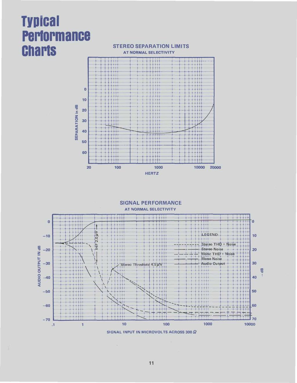
11 Performance Limits PERFORMANCE GUARANTEE - Performance limits are the maximum deviation from perfection permitted for a Mclntosh instrument. We promise you that the MR 78 you buy must be capable of performance at or exceeding these limits or you get your money back. Mclntosh is the only manufacturer that makes this guarantee. TUNING RANGE: 88 to 108 MHz ANTENNA INPUTS: 300 ohms balanced; 75 ohms unbalanced INTERMEDIATE FREQUENCY (IF): 10.7 MHz SENSITIVITY: 2µV for 35 db of quieting; 2.5µV at 100% modulation (±75 KHz deviation) for 3% total noise and harmonic distortion. SIGNAL TO NOISE RATIO: 75 db below 100% modulation. HARMONIC DISTORTION: 0.2% mono or stereo at 100% modulation to 15,000 Hz. Typically, 0.05% at 1,000 Hz DRIFT: 25,000 Hz for the first two minutes; thereafter 5,000 Hz at 25 C in 24 hours. FREQUENCY RESPONSE: MONO - ±1 db 20 Hz to 20,000 Hz with standard de-emphasis, (75µS); STEREO - ±1 db 20 Hz to 15,000 Hz with standard de-emphasis <75µS) CAPTURE RATIO: 0.25 db detector only; 2.5 db complete tuner SELECTIVITY: IHF SELECTIVITY SWITCH SETTING NORMAL NARROW SUPER NARROW Adjacent Channel 7 db 22dB 55dB Alternate Channel 55dB 80dB 80dB SUPURIOUS REJECTION: 100 db IHF IMAGE REJECTION: 100 db, 88 to 108 MHz. IHF INTERMODULATION DISTORTION: 0.2% mono or stereo for any combination of frequencies from 20 Hz to 15,000 Hz with peak modulation equal to 100% or less. Typically 0.1% MAXIMUM SIGNAL INPUT: 12 volts across 300 ohm antenna terminals will not increase harmonic or intermodulation distortion AUDIO HUM: 70 db down from 100% modulation MUTING: 70 db noise reduction between stations MUTING THRESHOLD (Typical): Distant position 5µV; Local position 20µV SCA FILTER: 50 db down from 67 KHz to 74 khz; 275 db per octave slope STEREO SEPARATION: 40 db at 1,000 Hz STEREO FILTER (Typical): 10 db noise reduction in Position db noise reduction in Position 2. AUDIO OUTPUT: Front Panel Controlled: 2.5 volts into47,000 ohms. Fixed Output: 2.5 volts into 47,000 ohms; 1.0 volt into 600 ohms. All tuner performance limits were measured with SELECTIVITY switch set at NORMAL, unless otherwise stated. GENERAL INFORMATION POWER REQUIREMENT: 120 volts, 50/60 Hz 35 watts SEMICONDUCTOR COMPLEMENT: 3 JFET's, 2 MOSFET's, 17 Bipolar Transistors, 43 Diodes, 4 Integrated Circuits MECHANICAL INFORMATION SIZE: Front Panel: 16 inches wide (40.65 cm) by5-7/16 inches high (13.8 cm); Chassis: 15 inches wide (38.1 cm) by 13 inches deep (33.1 cm), including PANLOC shelf and back panel connectors; Knob clearance" 1-1/2 inches (3.85 cm) in front of mounting panel. WEIGHT: 27 pounds (12.25 kg) net, 39 pounds (17.69 kg) in shipping carton. FINISH: Front panel: Anodized gold and black with special gold/teal panel nomenclature illumination; Chassis: Chrome and black MOUNTING: Mclntosh developed professional PAN- LOC 9

12
13

14 Technical Description TUNING MECHANISM AND DIAL DRIVE In the MR 78, the unique design and careful manufacture of the mechanical dial drive assembly gives smooth flywheel tuning. By controlling the relationship of mass and mechanical resistance, and by dividing the workloads in the dial drive system, it becomes nearly impossible to detect any backlash. Yet, the entire dial drive is a model of mechanical stability. For added ease and increased tuning accuracy, a section of the dial pointer is illuminated. FRONT END FM signals enter the tuner through the antenna terminals. A coaxial cable conducts the signal to the RF amplifier. In the amplifier the stations are separated, amplified, and converted to a common 10.7 MHz IF frequency. Instead of using a conventional easily overloaded transistor or FET as a straight RF amplifier, the MR 78 uses a rugged Junction Field Effect Transistor as an impedance converter to drive a 5-watt power transistor. This combination (a cascode circuit) makes the RF amplifier virtually impossible to overload or cross-modulate. As an example, if you are tuned to a 3 microvolt signal at 96.3 MHz, the MR 78 will reject signals elsewhere on the dial which are at least 4,000,000 times stronger. Thus, a 12 volt signal received at MHz would not bother the signal at 96.3 MHz. When tuned to MHz, the tuner will not overload. All MR 78 tuners must pass the 12 volt overload test. The MR 78 has an antenna matching circuit in the RF input. In fringe areas a broad low-loss RF circuit provides maximum sensitivity for a low-gain antenna. In metropolitan areas crowded with many strong signals, a sharp RF input circuit greatly reduces spurious responses and achieves maximum sensitivity when connected to a high-gain antenna. The RF bandpass of the antenna matching circuit can be modified by switching the resonator L1 C1 in or out of the circuit. Broad band pass is obtained by setting the ANTENNA MATCHING switch to the LOW GAIN ANT. position. This connects+24 volts to the circuit turning diode D1 off and diodes D2, D3 on. In this configuration the antenna is connected directly to the RF amplifier input resonator L2 C2. Diode D3 is tapped on L2 to yield optimum noise, while D2 shorts resonator L1 C1 so its loss is not coupled into the circuit. Sharp bandpass is obtained by setting the ANTENNA MATCHING switch to the HIGH GAIN ANT. position. This connects -12 volts to the circuit, turning diode D1 on and diodes D2, D3 off. The RF input circuit becomes a double tuned filter with high Q in both resonators, which provides sharp bandpass. Diode D1 is tapped on L1 to yield optimum selectivity. The oscillograph below shows the two bandpass curves of the RF input circuit. 12
15 Another new design in the MR 78 front end is the integrated circuit balanced mixer. This mixer is practically impossible to overload. Oscillator pulling, crossmodulation, and other types of distortion so common in ordinary transistor or FET mixers is minimized. A balanced bifilar transformer couples the 10.7 MHz output to the IF amplifier. Completing the MR 78 front end is the oscillator. It uses a high-q ceramic form tank coil. The oscillator is free form spurious radiations, and operates at high efficiency. AFC is not required. RIMO FILTER IF AMPLIFIER The MR 78 uses linear-phase IF filters. The Rimo filter, designed from a FORTRAN computer program, is the most general class of minimum-phase constantdelay filter. The filter design has great mathematical complexity. Using numerical integration in the S-plane, an "IBM" 1130 high speed computer spent eighteen minutes on the mathematics for the design of the IF filter. It would have taken an engineer, working twenty-four hours a day, seven days a week, and working error-free three-hundred years to perform the same mathematical calculations. The Rimo filter has flat time delay in its pass band region. Any error in time delay causes FM distortion. All other IF filters have delay distortion, as much as 100%. The MR 78 filter has less than 1.0% delay distortion from antenna input to discriminator output. Constant delay in the IF filter bandpass (which is equivalent to linear phase) is essential for low distortion FM reception. The MR 78 tuner uses linear phase (Rimo) filters at NORMAL and NARROW positions of the SELECTIVITY switch settings. For almost all reception conditions the tuner provides stereo signals that have the lowest possible distortion. 13 Constant delay design techniques are used in the 4-pole 4-zero crystal filter used in the SUPER NARROW position. However due to the extreme selectivity offered, delay distortion is very slightly increased over the other selectivity positions.
16 The MR 78 has the narrowest IF bandwidth ever used in a stereo tuner. It is the correct width to let just one FM station through. The excellent selectivity of the MR 78 {210 khz wide at 60dB down) permits tuning stations that are impossible to receive on ordinary tuners. LINEAR-PHASE BRIDGE DISCRIMINATOR The advantages of the Rimo filter would be lost if it had to work into an ordinary FM detector. A new detector had to be developed. It is the linear phase bridge discriminator. The linear-phase bridge discriminator uses a balanced transmission line bridge in conjunction with a differential voltage-doubling rectifier to acheive nearly distortionless demodulation of FM signals. Mclntosh has a US patent on this new FM detector. The resistors R1 and R3 form a Wheatstone bridge in combination with the two transmission line sections. The RF voltages E1 and E2 at the junctions of the resistors and the transmission lines will vary with frequency in such a manner that their RMS arithmetic difference (E1 - E2) is a straight-line function. Thus these RF voltages are peak rectified by an amplitude detector, and the difference taken, producing a distortionless recovery of the FM information. Ordinary stereo filters use a single capacitor. The MR 78 uses an elaborate twin-t bandpass filter. This circuit is much more effective in suppressing noise and still preserving the stereo image. AUDIO PREAMPLIFIER SECTION The audio amplifier increases the level of the program adequate to drive a preamplifier or other accessory equipment. It consists of two, two-transistor ampifiers, one for each channel. The design uses considerable negative feedback to help achieve low distortion, wide frequency response, and excellent stability. Each audio amplifier delivers 2.5 volts to the FIXED OUT- PUT jacks. A second pair of outputs are available where level can be varied by the VOLUME control. POWER SUPPLY Special design attention has been given to the power supply section. Two separate power circuits are used. The first is a 24 volt regulated supply. The 24volt regulator uses electronic filtering to insure the lowest possible background hum level, maximum stability and extremely good regulation. All signal stages are powered from this regulator. The second is a half wave rectifier with electronic filter which supplies DC to the multiplex decoder. BASIC LINEAR PHASE BRIDGE DISCRIMINATOR Performance of the MR 78 bridge discriminator has reduced distortion to nearly the theoretical zero. In addition to its excellent distortion-free performance, the bridge discriminator also exhibits a capture ratio close to 0 db. STEREO DECODER An integrated circuit audio amplifier with over 120 db of negative feedback in two loops is used to drive the stereo demodulator. This new circuit keeps the distortion low in the stereo mode of operation. Highly stable pilot recovery circuits are used to minimize 19,000 Hz intermodulation beats. MUTING, STEREO ONLY, and AUTOMATIC STEREO/MONO switching are functions performed within the stereo decoder. The STEREO FILTER is connected in the audio amplifier to reduce noise when listening to weak stereo stations. Careful design of the STEREO FILTER circuit permits an ideal compromise between channel separation and noise rejection. 14

17

18
19

20 McINTOSH LABORATORY INC. 2 CHAMBERS ST., BINGHAMTON, N. Y Design subject to change without notice. Printed in U.S.A BE122003
Contents. The Mclntosh compact Family MR 500 DIGITAL FM TUNER
 Contents SERVICE CONTRACT INFORMATION 1 INTRODUCTION 2 INSTALLATION 3, 4 BACK PANEL CONNECTIONS AND CONTROLS 5, 6 USING THE FRONT PANEL CONTROLS 7, 8 HOW THE CIRCUITS WORK 9, 10 PERFORMANCE LIMITS 11 PERFORMANCE
MR65 OWNER'S MANUAL STEREO FM TUNER ISSUE NO. 2. Reading Time 30 Minutes Price $1.25
 STEREO FM TUNER MR65 TABLE OF CONTENTS GENERAL DESCRIPTION 1 TECHNICAL DESCRIPTION 1 FRONT PANEL FACILITIES 2 Dial Scale 2 Meters 2 Volume Control 2 Mode Selector 2 Auto. Freq. Control 3 Muting 3 BACK
MR66 STEREO TUNER TABLE OF CONTENTS
 MR66 STEREO TUNER MR66 TABLE OF CONTENTS INTRODUCTION TECHNICAL DESCRIPTION FRONT PANEL INFORMATION BACK PANEL INFORMATION INSTALLATION CONNECTING Monophonic FM and AM Stereophonic FM and AM Stereophonic
MC24O OWNER'S MANUAL STEREO POWER AMPLIFIER CONTENTS
 STEREO POWER AMPLIFIER MC24O CONTENTS GENERAL DESCRIPTION 1 TECHNICAL DESCRIPTION 1 PANEL FACILITIES 4 INSTALLATION 5 CONNECTIONS 5 Input Stereo 5 Input Twin Amp 5 Input Mono 6 Output Stereo or Twin Amp
MC2505 STEREO POWER AMPLIFIER MC25O5 SOLID STATE PRICE $1.25
 MC2505 SOLID STATE STEREO POWER AMPLIFIER MC25O5 PRICE $1.25 The Mclntosh "will to perfection" requires that we probe constantly into the unknown to bring the performance of our electronic equipment closer
THE MclNTOSH MC 2300 SOLID STATE STEREO POWER AMPLIFIER
 THE MclNTOSH MC 2300 SOLID STATE STEREO POWER AMPLIFIER Price $1.25 The Mclntosh MC 2300 is a high quality, extremely high power, solid state stereo amplifier. Because of the high power available it is
FREQUENCY AGILE FM MODULATOR INSTRUCTION BOOK IB
 FMT615C FREQUENCY AGILE FM MODULATOR INSTRUCTION BOOK IB1215-02 TABLE OF CONTENTS SECTION SUBJECT 1.0 Introduction 2.0 Installation & Operating Instructions 3.0 Specification 4.0 Functional Description
FMR622S DUAL NARROW BAND SLIDING DE-EMPHASIS DEMODULATOR INSTRUCTION BOOK IB
 FMR622S DUAL NARROW BAND SLIDING DE-EMPHASIS DEMODULATOR INSTRUCTION BOOK IB 1222-22 TABLE OF CONTENTS SECTION 1.0 INTRODUCTION 2.0 INSTALLATION & OPERATING INSTRUCTIONS 3.0 SPECIFICATIONS 4.0 FUNCTIONAL
THE MclNTOSH MC 2255 SOLID STATE STEREO POWER AMPLIFIER
 THE MclNTOSH MC 2255 SOLID STATE STEREO POWER AMPLIFIER Reading Time: 31 Minutes Price $2.00 VARIOUS REGULATORY AGENCIES REQUIRE THAT WE BRING THE FOLLOWING INFORMATION TO YOUR ATTENTION. PLEASE READ IT
HF Receivers, Part 2
 HF Receivers, Part 2 Superhet building blocks: AM, SSB/CW, FM receivers Adam Farson VA7OJ View an excellent tutorial on receivers NSARC HF Operators HF Receivers 2 1 The RF Amplifier (Preamp)! Typical
Frequency range: BAND RANGE MHz MHz
 INSTRUCTION SHEET NO. 20 POWER-MITE PM3 and PM3A DESCRIPTION The Power-Mite 3 and 3A are self-contained CW transceivers covering 40 and 20 meters. The receiver is compromised of a variable oscillator operating
CON NEX HP. OWNER'S MANUAL Full Channel AM/FM Amateur Mobile Transceiver TABLE OF CONTENTS TUNING THE ANTENNA FOR OPTIMUM S.W.R..
 TABLE OF CONTENTS PAGE SPECIFICATIONS... 2 INSTALLATION... 3 LOCATION... 3 CON NEX - 4300HP MOUNTING THE RADIO... 3 IGNITION NOISE INTERFERENCE... 4 ANTENNA... 4 TUNING THE ANTENNA FOR OPTIMUM S.W.R..
MZ2 HEADPHONE AMPLIFIER, PREAMP, & STEREO AMPLIFIER USER GUIDE
 MZ2 HEADPHONE AMPLIFIER, PREAMP, & STEREO AMPLIFIER USER GUIDE Linear Tube Audio Takoma Park, MD, USA WARNING: For safety, the cover of this amplifier should be secured at all times. DC voltages as high
MC2301. Features and Benefits. Promotional Highlights TUBE POWER AMPLIFIER MCINTOSH LABORATORY INC., 2 CHAMBERS STREET, BINGHAMTON, NEW YORK 13903
 MC2301 Product Preview Page 1 McIntosh Laboratory, Inc., Binghamton, NY 13903 Design Engineering Department PRODUCT PREVIEW MC2301 TUBE POWER AMPLIFIER Project 1336 Promotional Highlights 300 Watts Mono
Amateur Radio Examination EXAMINATION PAPER No. 275 MARKER S COPY
 01-6-(d) An Amateur Station is quoted in the regulations as a station: a for training new radio operators b using amateur equipment for commercial purposes c for public emergency purposes d in the Amateur
ALM473 DUAL MONO \ STEREO AUDIO LEVEL MASTER OPERATION MANUAL IB
 ALM473 DUAL MONO \ STEREO AUDIO LEVEL MASTER OPERATION MANUAL IB6408-01 TABLE OF CONTENTS GENERAL DESCRIPTION 2 INSTALLATION 2,3,4 CONNECTION AND SETUP 4,5,6,7 FUNCTIONAL DESCRIPTION 8,9 MAINTENANCE 9
DX 33HML. Full Channel AM/FM Mobile Transceiver OWNER S MANUAL. Printed In Malaysia AT H PD000802
 DX 33HML Full Channel AM/FM Mobile Transceiver Printed In Malaysia AT3601014H PD000802 OWNER S MANUAL TABLE OF CONTENTS Page Specification.................................... 2 Installation Location.....................................
Registration 3. Owners Record Setup 4. Unit Connections 6. Front Panel Controls 8. Remote Control 9. Unit Care Technology 10. Designer s Note 12.
 Registration 3. Owners Record Setup 4. Unit Connections 6. Front Panel Controls 8. Remote Control 9. Unit Care Technology 10. Designer s Note 12. Specifications 2 The model and serial numbers are located
FM Stereo FM-AM Tuner
 3-861-346-12(1) FM Stereo FM-AM Tuner Operating instructions ST-SA50ES 1999 by Sony Corporation 1 GB WARNING To prevent fire or shock hazard, do not expose the unit to rain or moisture. This symbol is
DX 33HP. 10 Meter Amateur Mobile Transceiver OWNER S MANUAL. Download this Manual Free of Charge at
 DX 33HP SIG 1 3 TX PWR 5 7 9+30dB POWER HI NB/ANL MED LO HI LO BAND ECHO RX/TX VOL SQ MIC RF FM PA AM D/A E/B F/C ECHO TIME BAND 10 Meter Amateur Mobile Transceiver Download this Manual Free of Charge
FMT633S STEREO SYNTHESIZER MODULATOR INSTRUCTION BOOK IB
 FMT633S STEREO SYNTHESIZER MODULATOR INSTRUCTION BOOK IB 6114-01 TABLE OF CONTENTS GENERAL DESCRIPTION: 1 SPECIFICATIONS: 2 FUNCTIONAL DESCRIPTION: 3 INSTALLATION & OPERATING INSTRUCTIONS: 3-4 CAUTION:
Radio Receivers. Al Penney VO1NO
 Radio Receivers Al Penney VO1NO Role of the Receiver The Antenna must capture the radio wave. The desired frequency must be selected from all the EM waves captured by the antenna. The selected signal is
.2 Section Waste Management and Disposal..4 Section Electrical General Requirements.
 Issued 2006/08/01 Section 16724 Public Address System Page 1 of 8 PART 1 GENERAL 1.1 RELATED SECTIONS.1 Section 01330 Submittal Procedures..2 Section 01355 Waste Management and Disposal..3 Section 01780
MAC 1500 SERVICE MANUAL WARRANTY STATION MAC 1500 STEREO RECEIVER CONTENTS. 2 Chambers St., Binghamton, N.Y
 MAC 1500 STEREO RECEIVER WARRANTY STATION SERVICE MANUAL CONTENTS INTRODUCTION 1 FM ALIGNMENT CHART 2-3 MULTIPLEX DECODER ALIGNMENT CHART _ 4-5 SCHEMATIC 6-7 TESTS AND ADJUSTMENTS 8 DIAL STRINGING 8 S
FMC664CC FM BAND CONVERTER
 FMC664CC FM BAND CONVERTER INSTRUCTION BOOK IB6225/6226-01 COPYRIGHT 1995 ALL RIGHTS RESERVED NO PART OF THIS BOOK MAY BE REPRODUCED OR UTILIZED IN ANY FORM OR BY ANY MEANS, ELECTRONIC OR MECHANICAL, INCLUDING
The 21st Century R-390A/URR Reference Y2K-R3 Edited 7/09: No Technical Changes Chapter 2 - Operation. Page Table Of Contents 2-1
 Edited 7/09: No Technical Changes Chapter 2 - Operation Page Table Of Contents 2-1 2.1 Introduction. 2-2 2.2 Controls and Indicators 2-2 2.3 Operating Instructions And Control Settings 2-9 2.3.1 Pre-operational
ZOTL40 Mk.II POWER AMPLIFIER USER GUIDE. Linear Tube Audio Takoma Park, MD, USA
 ZOTL40 Mk.II POWER AMPLIFIER USER GUIDE Linear Tube Audio Takoma Park, MD, USA WARNING: For safety, the cover of this amplifier should be secured at all times. DC voltages as high as 1000V and peak AC
Model 7000 Low Noise Differential Preamplifier
 Model 7000 Low Noise Differential Preamplifier Operating Manual Service and Warranty Krohn-Hite Instruments are designed and manufactured in accordance with sound engineering practices and should give
OPERATING THE SYLVANIA STEREO RECEIVER RS4743
 OPERATING THE SYLVANIA STEREO RECEIVER RS3 TABLE OF CONTENTS Page Introduction 2 Accessory Components 3 Initial Hook-Up Connecting Accessory Components Antenna Connections Jacks Aux Jacks Tape Jacks Pre-Amp
LBI-30398N. MAINTENANCE MANUAL MHz PHASE LOCK LOOP EXCITER 19D423249G1 & G2 DESCRIPTION TABLE OF CONTENTS. Page. DESCRIPTION...
 MAINTENANCE MANUAL 138-174 MHz PHASE LOCK LOOP EXCITER 19D423249G1 & G2 LBI-30398N TABLE OF CONTENTS DESCRIPTION...Front Cover CIRCUIT ANALYSIS... 1 MODIFICATION INSTRUCTIONS... 4 PARTS LIST AND PRODUCTION
Radio Receivers. Al Penney VO1NO
 Radio Receivers Role of the Receiver The Antenna must capture the radio wave. The desired frequency must be selected from all the EM waves captured by the antenna. The selected signal is usually very weak
Installation... 3 Installing The Radio... 3 Ignition Noise Interference... 4 Antenna... 4 External Speaker... 4 Public Address...
 TABLE OF CONTENTS CHAPTER 1 Specifications.............................................. 2 PAGE BIG RIG SERIES S 1 MOD PW R 20 0 3 SW R 40 1 5 5 60 1.5 7 10 2 9 20 80 3 30 +20 40 50 +40 100% MAX db +60
DX 29HP. 10 Meter Amateur Mobile Transceiver OWNER S MANUAL PRINTED IN MALAYSIA PN:A412308CNA
 DX 29HP 10 Meter Amateur Mobile Transceiver OWNER S MANUAL PRINTED IN MALAYSIA PN:A412308CNA TABLE OF CONTENTS Page Specification.................................... 2 Installation Location.....................................
FMU623CA STEREO AUDIO PROCESSOR NARROW-BAND MONO SUBCARRIER INPUT FM STEREO BAND OUTPUT INSTRUCTION BOOK IB
 FMU623CA STEREO AUDIO PROCESSOR NARROW-BAND MONO SUBCARRIER INPUT FM STEREO BAND OUTPUT INSTRUCTION BOOK IB 1222-03 TABLE OF CONTENTS SECTION 1.0 INTRODUCTION 2.0 INSTALLATION & OPERATING INSTRUCTIONS
Module 8 Theory. dbs AM Detector Ring Modulator Receiver Chain. Functional Blocks Parameters. IRTS Region 4
 Module 8 Theory dbs AM Detector Ring Modulator Receiver Chain Functional Blocks Parameters Decibel (db) The term db or decibel is a relative unit of measurement used frequently in electronic communications
ERICSSONZ LBI-30398P. MAINTENANCE MANUAL MHz PHASE LOCKED LOOP EXCITER 19D423249G1 & G2 DESCRIPTION TABLE OF CONTENTS
 MAINTENANCE MANUAL 138-174 MHz PHASE LOCKED LOOP EXCITER 19D423249G1 & G2 TABLE OF CONTENTS Page DESCRIPTION... Front Cover CIRCUIT ANALYSIS...1 MODIFICATION INSTRUCTIONS...4 PARTS LIST...5 PRODUCTION
TOA PROFESSIONAL POWER AMP
 Operating Instruction Manual TOA PROFESSIONAL POWER AMP Model P-150M, P-300M TOA ELECTRIC CO, LTD. KOBE, JAPAN Contents Precautions... 2 General Description... 2 Features... 3 Specifications... 4~5 Performance
INSTRUCTIONS FOR INSTALLATION AND OPERATION OF THE MEISSNER SIGNAL SHIFTER MODEL EX
 INSTRUCTIONS FOR INSTALLATION AND OPERATION OF THE MEISSNER SIGNAL SHIFTER MODEL EX I. INTRODUCTION A. The MEISSNER SIGNAL SHIFTER is a variable frequency exciter, with output over the entire ranges of
MODEL 3 MONO AMPLIFIER OWNER S MANUAL
 MODEL 3 MONO AMPLIFIER OWNER S MANUAL TABLE OF CONTENTS Introduction Features Unpacking Instructions Installation * Space requirements * A.C. connections Input Impedance Selection Adjustable Gain Signal
Synthesized Base Station Transmitter
 BST-75 OPERATOR S MANUAL (72-76 MHz) Synthesized Base Station Transmitter 357 West 2700 South Salt Lake City, Utah 84115 Phone: (800) 496-3463 Fax: (801) 484-6906 www.comtek.com TABLE OF CONTENTS Introduction...
DX AM FM SSB CW PA Amateur Base Station Transceiver OWNER S MANUAL RX / TX 2 4 POWER NF CHANNEL MODE RF POWER OFF CAL OFF OFF CALIBRATE
 1 2 3 6 4050 ULA 6070 TI 80 90 100 9 DX 2517 2517 RX / TX 0 2 4 SWR WATTS SET 81012 22 1 010 3 2030 5 MOD 7 ON dbover 9 SIGNAL +20 +40+60 PA FM AM USB LSB CW POWER ON SWR NB / ANL R.BEEP +10KHz NF CHANNEL
Studio MODEL:PA600X/PA800X/PA1000X/ PA1800X PA AMPLIFIER PRO. High Performance Professional Audio.
 Studio PRO High Performance Professional Audio MODEL:PA600X/PA800X/PA1000X/ PA1800X PA AMPLIFIER www.pyramidcaraudio.com INTRODUCTION Your New PYRAMID PA SERIES AMPLIFIER gives you the power and versatility
IMPORTANT SAFETY INSTRUCTIONS
 IMPORTANT SAFETY INSTRUCTIONS THESE INSTRUCTIONS ARE TO PRO- TECT YOU AND THE MclNTOSH IN- STRUMENT. BE SURE TO FAMILIARIZE YOURSELF WITH THEM. 1. Read all instructions - Read the safety and operating
MC312 Power Amplifier Owner s Manual
 McIntosh Laboratory, Inc. 2 Chambers Street Binghamton, New York MC312 Power Amplifier Owner s Manual 13903-2699 Phone: 607-723-3512 www.mcintoshlabs.com Important Safety Information is supplied in a separate
VHF LAND MOBILE SERVICE
 RFS21 December 1991 (Issue 1) SPECIFICATION FOR RADIO APPARATUS: VHF LAND MOBILE SERVICE USING AMPLITUDE MODULATION WITH 12.5 khz CARRIER FREQUENCY SEPARATION Communications Division Ministry of Commerce
LBI-31564A. Mobile Communications. DELTA - SX MHz RADIO COMBINATIONS (NEGATIVE GROUND ONLY) Maintenance Manual
 Maintenance Manual") A Mobile Communications DELTA - SX 136-174 MHz RADIO COMBINATIONS (NEGATIVE GROUND ONLY) Maintenance Manual TABLE OF CONTENTS MILITARY AND SYSTEM SPECIFICATIONS................................. 2-3 COMBINATION
A Mobile Communications DELTA - SX 136-174 MHz RADIO COMBINATIONS (NEGATIVE GROUND ONLY) Maintenance Manual TABLE OF CONTENTS MILITARY AND SYSTEM SPECIFICATIONS................................. 2-3 COMBINATION
SE4 DSP + High Performance Professional Digital Stereo Encoder With DSP Filters
 PCS Electronics www.pcs-electronics.com info@pcs-electronics.com SE4 DSP + High Performance Professional Digital Stereo Encoder With DSP Filters SE4 DSP + without the LCD control module (connects to black
XES-M50 Operating Instructions
 3-859-268-11(1) XES-M50 Operating Instructions 1997 by Sony Corporation Stereo Power Amplifier Operating Instructions Before operating the unit, please read this manual thoroughly and retain it for future
MASTR II BASE STATION MHz RECEIVER IF/AUDIO/SQUELCH & RF ASSEMBLY (25 khz/12.5 khz CHANNEL SPACING) Maintenance Manual LBI-38506A
 Maintenance Manual LBI-38506A") A Mobile Communications MASTR II BASE STATION 806-824 MHz RECEIVER IF/AUDIO/SQUELCH & RF ASSEMBLY (25 khz/12.5 khz CHANNEL SPACING) TABLE OF CONTENTS RF ASSEMBLY, MIXER AND IF FILTER BOARD...... LBI-30482
A Mobile Communications MASTR II BASE STATION 806-824 MHz RECEIVER IF/AUDIO/SQUELCH & RF ASSEMBLY (25 khz/12.5 khz CHANNEL SPACING) TABLE OF CONTENTS RF ASSEMBLY, MIXER AND IF FILTER BOARD...... LBI-30482
DELUXE 18CHANNEL SSB/AM CB TRANSCEIVER OWNER'S GUIDE
 DELUXE 18CHANNEL SSB/AM CB TRANSCEIVER OWNER'S GUIDE General Description The Bush Ranger is a combination transmitter and receiver designed for use in the Australian 27 MHz Citizens radio service. It is
MC1000 POWER AMPLIFIER
 MC1000 POWER AMPLIFIER MC1000 POWER AMPLIFIER IMPORTANT SAFETY INSTRUCTIONS THESE INSTRUCTIONS ARE TO PROTECT YOU AND THE MclNTOSH INSTRUMENT. BE SURE TO FAMILIARIZE YOURSELF WITH THEM Copyright 1992
MODEL AF200A: FM, FM/SCA RECEIVER/MONITOR OPERATION MANUAL
 MODEL AF200A: FM, FM/SCA RECEIVER/MONITOR OPERATION MANUAL THE AF200A IS AN FM AND FM/SCA PROFESSIONAL STYLE RECEIVER/ MONITOR. IT S MANY APPLICATIONS INCLUDE STATION MONITORING AND EAS MONITORING. The
SOUNDMASTER VF 400 MOS-FET POWER AMPLIFIER OWNERS MANUAL
 SOUNDMASTER VF 400 MOS-FET POWER AMPLIFIER OWNERS MANUAL Table of Contents INTRODUCTION... 2 Introduction... 2 Technical Specification... 2 Protection Details... 2 Declaration of Conformity... 3 FRONT
RADIO RECEIVERS ECE 3103 WIRELESS COMMUNICATION SYSTEMS
 RADIO RECEIVERS ECE 3103 WIRELESS COMMUNICATION SYSTEMS FUNCTIONS OF A RADIO RECEIVER The main functions of a radio receiver are: 1. To intercept the RF signal by using the receiver antenna 2. Select the
Television and video engineering
 Television and video engineering Unit-4 Television Receiver systems Objectives: To learn the requirements of TV receiver Study of monochrome and Colour TV receivers. To learn functions of Tuning circuits
MC462 Quad Balanced Power Amplifier Owner s Manual
 McIntosh Laboratory, Inc. 2 Chambers Street Binghamton, New York MC462 Quad Balanced Power Amplifier Owner s Manual 13903-2699 Phone: 607-723-3512 www.mcintoshlabs.com Important Safety Information is supplied
FIELD INTENSITY METER MODEL FIM-41 OPERATING INSTRUCTIONS
 FIELD INTENSITY METER MODEL FIM-41 OPERATING INSTRUCTIONS POTOMAC INSTRUMENTS, INC. 932 Philadelphia Ave. Silver Spring, MD 20910 Phone (301) 589-2662 Fax (301) 589-2665 www.pi-usa.com 2.1 General SECTION
CALRAD 25 series - potentiometers
 25 series - potentiometers audio /linear SUB-MINIATURE VOLUME CONTROLS Linear taper, extremely smooth for quiet operation. 1 2" dia. fits into 1 4" hole. Shaft 3 16" dia. Thread length 7 32", shaft length
MASTR II AUXILIARY RECEIVER 19D417546G7 & G8 & ANTENNA MATCHING UNITS 19C321150G1-G2. Maintenance Manual LBI-30766L. Mobile Communications
 L Mobile Communications MASTR II AUXILIARY RECEIVER 19D417546G7 & G8 & ANTENNA MATCHING UNITS 19C321150G1-G2 Printed in U.S.A Maintenance Manual TABLE OF CONTENTS Page SPECIFICATIONS.....................................................
Operation Manual. SlJPER ST AR Channel Mobile 5-Mode Transceiver -----~- --:.. KTSS200NXX ,, I
 Operation Manual!.,, SlJPER ST AR 2000 200 Channel Mobile 5-Mode Transceiver -----~- --:.. KTSS200NXX General Description l Frequency/Channel Chart The Super Star -2000 is a combination transmitter-receiver
DX 66V OWNER S MANUAL. Full Channel AM/FM Mobile Transceiver Built in Frequency Counter with Roger Beep
 WARRANTY This radio is covered by a two year limited parts and labor warranty. Limited means that we will repair problems caused by factory defects or normal use at no charge. Before returning a radio
SXD SXD SXD SXD Dynamic Audio
 SXD SXD SXD SXD SXD 1000.1 2000.1 1100.2 1600.4 Dynamic Audio Company Message Congratulations on the purchase of your new SXD Series amplifier. Our engineers designed your amplifier with performance in
HAMTRONICS TB901 FM EXCITER INSTALLATION, OPERATION, & MAINTENANCE
 HAMTRONICS TB901 FM EXCITER INSTALLATION, OPERATION, & MAINTENANCE GENERAL INFORMATION. The TB901 is a single-channel low power fm transmitter (exciter) designed to provide 300-600 milliwatts continuous
Synthesized Base Station Transmitter
 BST-25 OPERATOR S MANUAL (216 MHz) Synthesized Base Station Transmitter 357 West 2700 South Salt Lake City, Utah 84115 Phone: (800) 496-3463 Fax: (801) 484-6906 http://www.comtek.com INTRODUCTION BST-25
Interference & Suppression Page 59
 INTERFERENCE Interference & Suppression Page 59 Front-End Overload, Cross-Modulation What is meant by receiver overload? Interference caused by strong signals from a nearby transmitter What is one way
TS-930: Installing the Inrad Roofing Filter Mod
 TS-930: Installing the Inrad Roofing Filter Mod The TS-930 roofing filter mod consists of a 6 pole, 4 to 5 khz wide filter followed by a high dynamic range, feedback amplifier. The amplifier provides enough
RCA Radiola 60 REG. U.S. PAT. OFF.
 RCA Radiola 60 REG. U.S. PAT. OFF. Super-Heterodyne AC Socket-Powered Instructions IB-60-1 Radio Corporation of America 233 Broadway New York City 100 West Monroe Street 235 Montgomery Street Chicago,
MFJ-219/219N 440 MHz UHF SWR Analyzer TABLE OF CONTENTS
 MFJ-219/219N 440 MHz UHF SWR Analyzer TABLE OF CONTENTS Introduction...2 Powering The MFJ-219/219N...3 Battery Installation...3 Operation Of The MFJ-219/219N...4 SWR and the MFJ-219/219N...4 Measuring
PROFESSIONAL POWER AMP
 Operating Instruction Manual PROFESSIONAL POWER AMP Model P-75D, P-150D, P-300D P-75D P-150D P-300D TOA Corporation KOBE, JAPAN Contents Precautions... 1 General Description... 2 Features... 2~ 3 Specifications...
On-Line Cardio Theater Wireless Digital Transmitter Installation and Instruction Manual
 On-Line Cardio Theater Wireless Digital Transmitter Installation and Instruction Manual Full installation instructions accompany your Cardio Theater equipment order. This On-Line version of our Installation/Instruction
The Walford Electronics Ford Receiver Kit Project Construction Manual
 The Walford Electronics Ford Receiver Kit Project Construction Manual Walford Electronics Ford Receiver construction manual V1.5 Page 1 of 22 Introduction The Ford receiver has four stages: The first stage
CALRAD MINIATURE MULTI-CLICK DUAL CONTROLS 40 STEP P.C. MOUNT 11
 25 Series - Potentiometers Audio & Linear SUB-MINIATURE VOLUME CONTROLS Linear taper, extremely smooth for quiet operation. 1 /2" dia. fits into 1 /4 hole. Shaft 3 /16" dia. Thread length 7 /32", shaft
TABLE OF CONTENTS. 1) Introduction 2. 2) Unpacking your preamplifier 2. 3) Installing the preamp into your system 3
 Introduction 2. 2) Unpacking your preamplifier 2. 3) Installing the preamp into your system 3") TABLE OF CONTENTS 1) Introduction 2 2) Unpacking your preamplifier 2 3) Installing the preamp into your system 3 4) Operation of your preamplifier 6 5) Troubleshooting 8 6) Registration of your preamplifier
TABLE OF CONTENTS 1) Introduction 2 2) Unpacking your preamplifier 2 3) Installing the preamp into your system 3 4) Operation of your preamplifier 6 5) Troubleshooting 8 6) Registration of your preamplifier
Distribution Amplifiers 1
 Distribution Amplifiers 1-30dB PUT 49-750 MHz 43 db GA POWER DOUBLED P/N: 1002705 REVERSE GA M MAX DESCRIPTION The R.L. DRAKE models DA8642, DA8632,, and DA7533, are broadband distribution amplifiers designed
Technician Licensing Class. Lesson 4. presented by the Arlington Radio Public Service Club Arlington County, Virginia
 Technician Licensing Class Lesson 4 presented by the Arlington Radio Public Service Club Arlington County, Virginia 1 Quiz Sub elements T6 & T7 2 Good Engineering Practice Sub element T8 3 A Basic Station
CXA CXA CXA CXA CXD M. Dynamic Audio
 CXA CXA CXA CXA CXD 640 1040 820 1220 2800M Dynamic Audio Company Message Congratulations on the purchase of your new CX Series amplifier. Our engineers designed your amplifier with performance in mind,
audionet 4 Channel Amplifier Owner's Manual
 audionet amp Iv 4 Channel Amplifier Owner's Manual Congratulations! For those in need of even more amplification we have engineered the AMP IV. The AMP IV is our power amplifier for multichannel applications
GE Monogram. Installation. Instructions. Microwave Oven. Under Cabinet Installation. and. JX827 Series Built-In Kit. Models.
 GE Monogram Installation Instructions Under Cabinet Installation and JX827 Series Built-In Kit Models ZEM200 Series CAUTION WARNING Before you begin Read these instructions completely and carefully. IMPORTANT:
MFJ-203 Bandswitched Dip Meter
 MFJ-203 Bandswitched Dip Meter Thank you for purchasing the MFJ-203 Bandswitched Dip Meter. The MFJ-203 Bandswitched Dip Meter is a solid state bandswitched adaptation of the traditional grid dip meter.
INSTRUCTION MANUAL LCS TX
 INSTRUCTION MANUAL LCS TX 4 Channel Transmitter LCS1 Single Channel Transmitter Cardio Theater Inc Service 1-800-776-6695 Sales 1-800-CARDIO-1 1 Introduction CONGRATULATIONS on your choice of this product
LBI-4938C. Mobile Communications MASTR II POWER AMPLIFIER MODELS 4EF4A1,2,3. Printed in U.S.A. Maintenance Manual
 C Mobile Communications MASTR II POWER AMPLIFIER MODELS 4EF4A1,2,3 Printed in U.S.A. Maintenance Manual TABLE OF CONTENTS DESCRIPTION.................................................... 1 CIRCUIT ANALYSIS.................................................
Central Electronics Model 600L Linear Amplifier
 INTRODUCTION This manual has been reproduced by James Lawrence, NA5RC, a 600L owner. Text no longer applicable such as insurance claim with the carrier has been deleted. Some capitalization and grammar
19'' Rack Mount 300 Watt Power Amplifier/ Mixer w/70v Output & Mic Talkover USER MANUAL
 19'' Rack Mount 300 Watt Power Amplifier/ Mixer w/70v Output & Mic Talkover USER MANUAL Your new PYRAMID PA305 300 Watt P.A. Amplifier gives you the power and versatility you need in a professional sound
ENCORE 200 VHF Bass Wireless Microphone System
 ENCORE 200 VHF Bass Wireless Microphone System Nady Wireless Systems are type accepted under FCC rules parts 90, 74 and 15. The device complies with RSS-210 of Industry & Science Canada. Operation is subject
CAVITY TUNING. July written by Gary Moore Telewave, Inc. 660 Giguere Court, San Jose, CA Phone:
 CAVITY TUNING July 2017 -written by Gary Moore Telewave, Inc 660 Giguere Court, San Jose, CA 95133 Phone: 408-929-4400 1 P a g e Introduction Resonant coaxial cavities are the building blocks of modern
Mirage B-320-G FEATURES
 Mirage B-320-G The Mirage B-320-G is a VHF power amplifier designed for 2 meters covering 144-148 MHz. The Hi and Lo input selector switch makes this amp useable for both handheld and mobile transceivers.
TDQ-150 Stereo Tuner
 O W N E R ' S M A N U A L TDQ-150 Stereo Tuner TDQ-150 Stereo Tuner FM-AM Preset On-Off Tune FM STEREO 105.35 15 MHz CH -1- Table of Contents Important Safety Instructions...3 Front, Rear Panel, and Remote
i. AM. Radio Transmitter Installation and Operation Easy to follow instructions on how to program and use your Model 5.0 i. AM.
 i. AM. Radio Transmitter Installation and Operation Easy to follow instructions on how to program and use your Model 5.0 i. AM. Radio Transmitter Contents Quick Start...3 Front and Rear Panel Controls...5
USER MANUAL MG-TA1000 POWER AMPLIFIER
 USER MANUAL MG-TA1000 POWER AMPLIFIER INDEX: INTRODUCTION SAFETY INSTRUCTIONS OPERATING PRECAUTIONS FEATURES OF PANAL CONTROLS FRONT & REAR PPANEL DISPLAY CONNECTING INPUTS SPEAKER CONNECTIONS INTRODUCTION:
When you check the list of features offered by the PLMRA220,PLMRA420 you ll know you made the right choice with a Pyle Marine amplifier.
 congratulations... on your purchase of a Pyle Marine Series amplifier. This amplifier extends the Pyle tradition into a totally new series of amps, designed from the ground up to deliver the power, performance
PR-216. High Performance Personal Receiver PR-216 OPERATOR S MANUAL
 PR-216 OPERATOR S MANUAL PR-216 High Performance Personal Receiver 357 West 2700 South Salt Lake City, Utah 84115 Phone: (800) 496-3463 Fax: (801) 484-6906 http://www.comtek.com TABLE OF CONTENTS Introduction...
SPECIFICATIONS: Subcarrier Frequency 5.5MHz adjustable, FM Modulated +/- 50KHz. 2nd 11MHz >40dB down from 5.5MHz
 Mini-kits AUDIO / SUBCARRIER KIT EME75 Version4 SPECIFICATIONS: Subcarrier Frequency 5.5MHz adjustable, FM Modulated +/- 50KHz Subcarrier Output 1.5v p-p Output @ 5.5MHz DESCRIPTION & FEATURES: The Notes
Magnum Dynalab MD 90/90R ANALOG FM TUNER
 Magnum Dynalab MD 90/90R ANALOG FM TUNER INSTRUCTION MANUAL - 2 - TABLE OF CONTENTS A MESSAGE FROM THE PRESIDENT 3 UNPACKING YOUR MD 90 4 SETTING UP YOUR MD 90 5 CONTROLS AND FUNCTIONALITY 6 DISPLAYS AND
HQ-31 HQ-15 USER S GUIDE SINGLE CHANNEL 31 BAND 1/3 OCTAVE GRAPHIC EQUALIZER DUAL CHANNEL 15 BAND 2/3 OCTAVE GRAPHIC EQUALIZER
 HQ-31 SINGLE CHANNEL 31 BAND 1/3 OCTAVE GRAPHIC EQUALIZER HQ-15 DUAL CHANNEL 15 BAND 2/3 OCTAVE GRAPHIC EQUALIZER USER S GUIDE GENERAL INFORMATION SINGLE CHANNEL 31 BAND 1/3 OCTAVE GRAPHIC EQUALIZER WITH
411LA Broadband Power Amplifier
 411LA Broadband Power Amplifier HIGH RF VOLTAGES MAY BE PRESENT AT THE OUTPUT OF THIS UNIT. All operating personnel should use extreme caution in handling these voltages and be thoroughly familiar with
Power Amplifier. MC501 Owner s Manual
 Power Amplifier MC501 Owner s Manual McIntosh Laboratory, Inc. 2 Chambers Street Binghamton, New York 13903-2699 Phone: 607-723-3512 FAX: 607-724-0549 The lightning flash with arrowhead, within an equilateral
TOA NEW 900 SERIES MIXER PREAMPLIFIER M-900A
 Operation Instruction Manual TOA NEW 900 SERIES MIXER PREAMPLIFIER M-900A Features General Description 1 6-channel mixer preamplifier 2 Wide frequency response; 20 20,000Hz, ±1dB 3 Low distortion and noise
900MHz Digital Hybrid Wireless Outdoor Speakers
 4015004 900MHz Digital Hybrid Wireless Outdoor Speakers User s Manual This 900 MHz digital hybrid wireless speaker system uses the latest wireless technology that enables you to enjoy music and TV sound
OWNER S MANUAL 311DRH 311DR 221R 211R 200R 31LT 31IT 32BT 32IT 31HT 31XT
 VHF PERFORMANCE SERIES WIRELESS MICROPHONE SYSTEMS OWNER S MANUAL 311DRH 311DR 221R 211R 200R 31LT 31IT 32BT 32IT 31HT 31XT AZDEN CORPORATION P.O. Box 10-147 New Hyde Park Road Franklin Square, NY 11010
AM/FM SYNTHESIZER TUNER
 OPERATING INSTRUCTIONS AM/FM SYNTHESIZER TUNER DT-930 UL TABLE OF CONTENTS 1. IMPORTANT SAFETY INSTRUCTIONS... 2 2. SAFETY PRECAUTIONS... 2 3. INFORMATION TO THE USER... 3 4. GENERAL DESCRIPTION... 3 5.