Jan Iżykowski. Fault location on power transmission lines
|
|
|
- Brice Ryan
- 6 years ago
- Views:
Transcription
1
2 Jan żykowsk Fault locaton on power transmsson lnes Ofcyna Wydawncza Poltechnk Wrocławskej Wrocław 8
3 Revewer Andrzej WSZNEWSK Edtoral layout and proof-readng Halna MARCNAK Cover desgn Justyna GODLEWSKA-SKERKA The cover mage s based on the orgnal photo by Andrzej Marek CURASZKEWCZ. All rghts reserved. No part of ths book may be reproduced by any means, electronc, photocopyng or otherwse, wthout the pror permsson n wrtng of the Publsher and the Copyrght-holder. Copyrght by Jan żykowsk, Wrocław 8 OFCYNA WYDAWNCZA POLTECHNK WROCŁAWSKEJ Wybrzeże Wyspańskego 7, 5-37 Wrocław e-mal: ofcwyd@pwr.wroc.pl SBN Drukarna Ofcyny Wydawnczej Poltechnk Wrocławskej. Zam. nr 97/8.
4 Contents Preface... 5 A Note for the Reader ntroducton Am of fault locaton and ts mportance Fault locators versus protectve relays Fault locaton methods mpedance-based fault locaton bascs Fault locator nput sgnals Tme ntervals of fault locator nput sgnals Sgnal processng methods for fault locaton Synchronsaton of dstrbuted dgtal measurements Fault locaton errors Transmsson network models for fault locaton studes Network confguratons Networks wth sngle-crcut overhead lnes Networks wth double-crcut lnes Mult-termnal and tapped lnes Overhead lne and cable composte networks Networks wth seres-compensated lnes Models of overhead lnes Lumped-parameter models Dstrbuted-parameter models Modal transformaton Transmsson lne faults ntroducton Fault types Fault statstcs Models of resstve faults n symmetrcal components Models of resstve faults n phase co-ordnates Arcng faults Dynamc model of arc Statc model of prmary arc Measurement chans of fault locators ntroducton Voltage transformers Transent performance of capactve voltage transformers Dynamc compensaton of capactve voltage transformers Current transformers Bascs of current transformers Fault locaton under saturaton of current transformers... 89
5 Analogue ant-alasng flters One-end mpedance-based fault locaton algorthms ntroducton Fault locaton based on mpedance measurement Use of fault current dstrbuton factors Transmsson network wth sngle lne Transmsson network wth double-crcut lne Models of fault loops Fault locaton algorthm by Takag et al Fault locaton algorthm by Wsznewsk Fault locaton algorthm by Saha et al Fault locaton algorthm for a double-crcut lne wth complete measurements at one lne end Fault locaton algorthm for a double-crcut lne wth lmted measurements at one lne end Fault locaton algorthm utlsng only phase current phasors Fault locaton wth lmted use of current phasors Fault locaton and arc voltage estmaton algorthm Fault locaton on untransposed lnes Fault locaton on seres-compensated lnes Representaton of SC&MOV bank Fault locaton algorthm for sngle seres-compensated lnes Applcaton of dstrbuted-parameter lne model to one-end fault locaton algorthms Two-end and mult-end fault locaton algorthms ntroducton Fault locaton wth use of two-end synchronsed measurements Phasor-based approach Tme doman approach Fault locaton wth use of two-end unsynchronsed measurements Fault locaton wth measurement of synchronsaton angle Fault locaton wth elmnaton of synchronsaton angle Fault locaton algorthm by Novosel et al Optmal fault locaton algorthm Fault locaton wth analytcal synchronsaton of measurements of dstance relays from lne termnals Fault locaton wth use of unsynchronsed measurements of dstance relays from lne termnals Fault locaton wth use of ncomplete two-end measurement Fault locaton wth use of two-end voltages Fault locaton wth use of two-end voltages and one-end current Fault locaton wth use of two-end currents and one-end voltage Fault locaton wth exchange of lmted nformaton Fault locaton on three-termnal lnes Fault locaton on three-termnal lnes wth use of three-end measurements Fault locaton on three-termnal lnes assocated wth current dfferental protectve relays Fault locaton on three-termnal lnes wth use of two-end measurements Fault locaton on three-termnal lnes wth use of mnmal measurements Fault locaton on mult-termnal and tapped lnes... 4 Afterword... 7 References... 9
6 Preface mportance of fault locaton Electrc power systems have grown rapdly over the past ffty years. Ths has resulted n a huge ncrease of the number of overhead power lnes n operaton and ther total length. These lnes experence faults due to varous causes. n most cases, electrcal faults manfest themselves n mechancal damage, whch must be repared before the lne s put back to servce. The restoraton can be expedted f the locaton of the fault s ether known or can be estmated wth good accuracy. Fault locators provde estmate for both sustaned and transent faults. The subject of fault locaton has been of consderable nterest to electrc power utlty engneers and researchers for several decades. Most of the research done to date has been amed at fndng the locatons of transmsson lne faults. Ths s manly because of the mpact of transmsson lne faults on the power systems and the tme requred to physcally check the lnes s much longer than n the case of faults occurrng n other power system components. Recently, the locaton of faults has receved growng attenton as many utltes operate n a deregulated envronment and compete wth each other to ncrease the avalablty of power supply to the customers, assurng at the same tme adequate qualty of power. Research on fault locaton conducted at the Wrocław Unversty of Technology The research nto transmsson lne fault locaton at the nsttute of Electrcal Power Engneerng of the Wrocław Unversty of Technology (WrUT) has been ntated by Prof. Andrzej Wsznewsk more than 5 years ago. n 983, Prof. Andrzej Wsznewsk developed the fundamental one-end fault locaton algorthm, whch s stll often referred to n the fault locaton lterature worldwde. Then, n 994, our team of researchers started co-operaton wth the ABB AB n Västerås (Sweden), under the supervson of Dr. Murar Mohan Saha (ABB) and Prof. Eugenusz Rosołowsk (WrUT). t was a great pleasure for me to be a member of ths team and to be gven the possblty of jont work on the fault locaton and protectve relayng ssues. Also, apprecate very much the co-operaton wth Dr. Bogdan Kasztenny, prevously afflated wth the WrUT and presently wth the GE Multln Markham, Canada. For the last three years the research has been governed by the ABB Corporate Research Center n Kraków. A part of the research was conducted wthn the grants of the Mnstry
7 6 Preface of Scence and Hgher Educaton of Poland, as well as wthn the Ph.D. theses completed by Dr. Rafał Kaweck, Dr. Przemysław Balcerek and Dr. Rafał Moląg, under my supervson. Acknowledgements My sncere grattude goes to everyone who worked wth me durng the research on the fault locaton, wthn the project conducted n co-operaton wth ABB AB, especally to Dr. Murar Mohan Saha and Prof. Eugenusz Rosołowsk. Also, would lke to thank warmly all the academc staff members of the Power System Control and Protecton Group. Ths wonderful research group was ntally led by Prof. Andrzej Wsznewsk, then by Prof. Janusz Szafran, and lately by Prof. Eugenusz Rosołowsk. t s my great pleasure and satsfacton to belong to the team, n whch there s an unusual atmosphere of work and frendshp. Specal thanks are due to the revewer of ths book Prof. Andrzej Wsznewsk for hs effort n the revewng and many suggestons as to the changes and mprovements. Fnally, my deepest apprecaton goes to my famly for lmtless patence and understandng. Jan żykowsk Wrocław, July 8
8 A Note for the Reader Ths book deals wth fault locaton on transmsson lnes. Among many fault locaton methods, the mpedance-based method has been taken for detaled consderatons. n ths method, the mpedance parameters of the faulted lne secton are consdered as a measure of the dstance to fault. The mpedance-based fault locaton appears to be stll the most popular method. Ths s so, snce mpedance-based fault locaton algorthms exhbt varous advantages and can be easly mplemented nto the products offered by the numerous manufacturers. The book begns (Chapter ) wth explanng the am of fault locaton and ts mportance. n partcular, the fault locators are consdered as the devces that dffer n many aspects from protectve relays. Then, dfferent fault locaton methods are shortly charactersed. n Chapter, the bascs of the mpedance-based fault locaton are presented. Dvson of fault locaton algorthms wth respect to the fault locator nput sgnals s performed and tme ntervals of fault locator nput sgnals are defned. Then, sgnal processng methods for fault locaton are shortly revewed. n relaton to use of dstrbuted dgtal measurements to fault locaton, ther synchronsaton wth the ad of the GPS or by analytcal synchronsaton s descrbed. The fault locaton error s defned and the sources of errors are charactersed. Chapter 3 revews dfferent confguratons of the networks. The networks contanng sngle-crcut lnes, double-crcut lnes, mult-termnal and tapped lnes, composton of overhead lne and cable, and seres-compensated lnes are presented. Then, the lumped-parameter and dstrbuted-parameter lne models are presented. The modal transformatons are gathered. n Chapter 4, the bascs of transmsson lne faults are provded. The fault models are formulated usng symmetrcal components and phase co-ordnates approach. The analyss of arcng faults, ncludng typcal waveforms of current and voltage sgnals, obtaned from the ATP-EMTP smulaton, s presented. Chapter 5 s focused on the measurement chans of fault locators. Transent performance of capactve voltage transformers and ther dynamc compensaton are consdered. The bascs for current transformers are gven. t has been shown how to counteract the negatve effects of the possble saturaton of current transformers, when
9 8 A Note for the Reader dervng fault locaton algorthms. The desgn of analogue low-pass flters s addressed. n Chapter 6, a varety of one-end mpedance-based fault locaton algorthms are presented. To ths end, a unform descrpton of the faults and the fault loops has been appled. The algorthms presented are desgned for locatng faults on sngle-crcut lnes, double-crcut lnes and seres-compensated lnes. Both transposed and untransposed lnes are taken nto consderaton. The algorthms are formulated for the lumped lne models, however, at the end of the chapter, the way of mprovng fault locaton accuracy by ntroducng the dstrbuted-parameter lne model s presented. Chapter 7 s focused on two-end and mult-end fault locaton algorthms. Frst, the algorthms utlsng two-end synchronsed measurements are presented for both phasor-based and tme doman approaches. Then, the unsynchronsed measurements as appled to fault locaton are consdered n detal. Dfferent optons for measurng the synchronsaton angle are ntroduced and varous fault locaton algorthms are presented. Complete and ncomplete two-end measurements are taken nto account. Algorthms utlsng measurements of dstance relays from lne termnals are descrbed. Fault locaton on three-termnal and mult-termnal lnes s addressed. The author presents fault locaton algorthms developed by hmself or n cooperaton, as well as algorthms selected from the vast lterature of the subject. When presentng fault locaton on seres-compensated lnes, the consderatons are ntentonally lmted to the basc network confguraton wth a sngle-crcut lne and to usng the one-end measurements. The other fault locaton algorthms can be found n the lterature.
10 . ntroducton.. Am of fault locaton and ts mportance Rapd growth of electrc power systems over the last decades has resulted n a large ncrease n the number of transmsson and dstrbuton lnes [B, B, B3] n the world. At the same tme, free marketng and de-regulaton ntroduced all over the world mpose more and more restrctve requrements on provdng a contnuous and good qualty power supply, wthout any sgnfcant ncrease n the cost of energy beng delvered. The terms such as contnuty of power supply, dependablty and relablty play a very mportant role n contemporary power systems. As a result of mposng restrctve requrements, an ncreased demand for hgh-qualty power system protecton and control devces together wth ther supplementary equpment became a matter of prme mportance. Among the dfferent functons of those devces the fault locaton s consdered to be very mportant [B.7, B.9, B., B.6, B9, B,, 6]. Fault locaton s a process amed at locaton of the fault wth the hghest accuracy possble. Fault locators are n general the supplementary protecton equpment, whch apply the fault locaton algorthms for estmatng a dstance to the fault. When locatng faults on a lne consstng of more than one secton (mult-termnal lne), ntally a faulted secton has to be dentfed and then a fault on ths secton has to be located. Fault locaton functon can be mplemented n [B.9, B.6]:. mcroprocessor-based relays,. dgtal fault recorders (DFRs), 3. stand-alone fault locators, 4. post-fault analyss programs. ncludng the fault locaton as an addtonal functon n mcroprocessor-based relays s a common practce. n ths case, hgh computatonal capablty and communcaton wth remote stes of modern relays are taken advantage of at lttle or almost no addtonal cost. Also, dgtal fault recorders enable an easy and not costly ncorporaton of the fault locaton functon. n turn, stand-alone fault locators are appled n the case of usng sophstcated fault locaton algorthms and on condton that hgher cost of the mplementaton s accepted. Yet, there s another possblty whch concerns
11 Chapter post-fault analyss programs [64] wth fault locaton algorthms ncluded. Such programs are manly used for verfcaton of the operaton of protectve relays. Transmsson and dstrbuton lnes experence temporary and permanent faults. Temporary faults, whch are most frequent on overhead lnes, n many cases could be self-cleared. n consequence, the contnuty of power supply s not permanently affected, whch s advantageous. n turn, upon the occurrence of permanent fault, the protectve relayng equpment, usng crcut breakers, enables the faulted sectons to be deenergzed. f a gven lne s put out of servce, the connected loads are not suppled or, f possble, the other lnes are forced to supply the loads of the trpped lne. t s also possble that a seres of cascadng trppngs may happen, takng out of servce successvely larger and larger parts of the system. Under some unfavourable crcumstances, ths may even lead to blackouts of large power systems, as has recently happened n some countres. Contemporary power systems get closer and closer to ther operatng lmts. Therefore, n order to avod blackouts specal attenton must be pad to equppng power systems wth protecton and control devces, as well as to ther settngs. n the case of permanent faults, power supply can be restored after the mantenance crew have fnshed the repar of the damage caused by the fault. For ths purpose, the fault poston has to be known, otherwse the whole lne has to be nspected for fndng the place of damage. Thus, t s mportant to know the locaton of a fault or to locate t wth possbly hgh accuracy. Ths allows us to save money and tme spent on nspecton and repar, as well as to provde a better servce due to the possblty of faster restoraton of power supply. Also, blackouts can be avoded ths way. Temporary faults are self-cleared and do not permanently affect the contnuty of supply, however, the locaton of such faults s also mportant. n ths case, the fault locaton can help pnpont the weak spots on the lne, and therefore, t should be ncluded n mantenance schedules to avod serous problems n the future. Even f helcopters are mmedately avalable for patrol followng unsuccessful reclosng, fault locators perform a valuable servce. Trouble cannot always be found by a routne patrol wth no ndcaton of where the fault occurred. For example, tree growth could reduce clearances, resultng n a flashover durng severe conductor saggng. By the tme the patrol arrves, the conductors have cooled, makng the clearance to the tree ncrease. The weak spot s not well recognzed [64]. The mportance of fault locators s more obvous where foot patrols are reled upon, partcularly on long lnes, n rough terran. Also, these can help where mantenance jursdcton s dvded between dfferent companes or dvsons wthn a company. Fault locators are valuable even where the lne has been restored ether automatcally or non-automatcally. n ths category are the faults caused by cranes swngng nto the lne, brushfres, damaged nsulators and vandalsm. The locator allows rapd arrval at the ste before the evdence s removed or the tral becomes cold. Also, the knowledge that repeat faults are occurrng n the same area can be valuable n detect-
12 ntroducton ng the cause. Weak spots that are not obvous may be found because a more thorough nspecton can be focused n the lmted area defned by the fault locator... Fault locators versus protectve relays Fault locators and protectve relays are closely related, however, there are some mportant dfferences between them. These dfferences can be consdered as related to the followng features [B.6]:. accuracy of fault locaton,. speed of determnng the fault poston, 3. speed of transmttng data from remote ste, 4. used data wndow, 5. dgtal flterng of nput sgnals and complexty of calculatons. The above can be further explaned as follows:. Fault locators are used for pnpontng the fault poston accurately and not only for ndcaton of the general area (defned by a protectve zone) where a fault occurred whch s provded by protectve relays.. n the case of protectve relays, both the measurement and decson makng are performed n an on-lne regme. Hgh speed of operaton of protectve relays appears as a crucal requrement mposed on them. Ths s so snce n order to prevent spreadng out the fault effects, the faulted lne has to be swtched-off as quckly as possble. Therefore, hgh speed measurng algorthms are appled n contemporary protectve relays, and use of hgh-speed operatng crcut breakers s also of prme mportance. Fault clearng tme s an mportant consderaton n the selecton of protectve relays and requrements for relayng speed must be carefully determned. f the relayng s too slow, system nstablty, excessve equpment damage, and adverse effects on customer servce may result. On the other hand, faster protecton tends to compromse relay system securty and selectvty. The requrement for the fast clearng of faults demands that the decson for trppng transmsson lnes has to be made n a short tme, even faster than n one cycle of the fundamental frequency ( ms for the systems operatng at 5 Hz). n contrast, the calculatons of fault locators are performed n an off-lne mode snce the results of these calculatons (poston of the fault and n the case of some algorthms also the fault resstance nvolved) are for human users. Ths mples that the fault locaton can be longer and take seconds or even mnutes. 3. Low-speed data communcatons or Supervsory Control and Data Acquston (SCADA) can be appled for fault locaton purposes, whch dffers from communcaton used by protectve relays. 4. The best data wndow segment from the whole avalable wndow can be selected for fault locaton to reduce errors. Ths s so snce the computatons are per-
13 Chapter formed n an off-lne regme and searchng for the best data wndow can be easly appled. The fault nterval lasts from a fault ncpence up to a fault clearng by a crcut breaker, and usually ths takes around three fundamental frequency cycles, whch s suffcent for fault locaton. 5. n the case of the protectve relays the hgh speed requred causes that the calculatons are not to be too complex nor much tme-consumng. n contrast, fault locaton calculatons have no such lmtatons. Therefore, more accurate phasor calculaton for fault locaton, ncludng rejecton of dc components, can be appled. Also, the models of the power lne and the fault n fault locaton algorthms are usually more advanced than for relayng. Among dfferent types of relays commonly used for protectng power lnes, dstance relays [B.3, B.8, B., B.4, B.5, 8] are the most related to fault locators. These relays are desged for fast and relable ndcaton of the general area where a fault occurred. f the fault s recognzed as occurrng wthn the pre-defned protectve zone, then a trp sgnal to the correspondng crcut breaker s sent mmedately. n consequence, the fault becomes solated quckly, whch mnmses the mpact of a fault on a power network. Dstance relays have multple protecton zones for provdng back capablty. The relay that detects the fault n the st zone s desgned to trp frst. Generally, a par of dstance relays s used to protect a two-termnal lne. Usually, they can communcate wth each other, formng a plot relayng. As a result of exchangng nformaton between the dstance relays from the lne termnals, they both could trp wthn the st zone. The operaton of a dstance relay may be sgnfcantly nfluenced by the combned effect of load and fault resstance, whch s known as the reactance effect [8, 3, 8]. The dstance relay may msoperate for a forward external fault, or may not operate for an nternal fault f the value of the fault resstance s too large. The value of the fault resstance may be partcularly large for ground faults, whch are the most frequent faults on overhead lnes. The nfluence of fault resstance on measurement performed by dstance relays s explaned n Fgs.. and.. The explanaton s performed n relaton to a sngle phase case, whch can be easly extended to a three-phase one, wth dfferent fault types beng consdered [8, 3, 8]. Fgure. shows a crcut dagram of the transmsson network experencng a fault (F), nvolvng resstance (R F ), on a homogeneous sngle-phase lne wth mpedance (Z L ) between buses S and R. For the sake of smplcty, a lumped lne model s taken nto account, wth shunt capactances beng neglected. Parts of the network behnd the local (S) and remote (R) termnals are replaced by the Thevenn equvalents contanng EMFS and equvalent source mpedances [B.]. The fault loop seen from the bus S can be descrbed wth the followng formula, usng the phasor notaton:
14 ntroducton 3 V d Z R (.) S L S F F = where: d dstance from the bus S to fault pont F, expressed n relatve unts (p.u.), V S, S voltage and current measured at the measurement pont (here at the bus S), F total fault current (flowng through the fault path resstance), whch for the assumed lumped lne model and neglected shunt capactances, equals: = + (.) F S The formula (.) can be wrtten as: V S F Z S = = d Z L + RF (.3) S where Z S mpedance determned on the bass of the voltage and current measured at pont S. From (.3) t s seen that the mpedance Z S s a strct measure of the dstance to fault (d), only f the fault resstance s equal to zero or s very low and can be neglected. Otherwse, the fault resstance R F s seen, n general, as a certan mpedance: R + R S # S R F = RF (.4) S Dependng on the currents at both lne ends ( S, R ), the fault resstance R F can be # seen as R F, whch presents: pure resstance (Fg..a), resstance and capactve reactance (Fg..b), resstance and nductve reactance (Fg..c). n the last two cases (Fgs..b and c), the reactance (capactve or nductve) s observed to contrbute to resstance, and that s why such an effect s called reactance effect [3, 36, 68, ]. E S Z S S dz L F ( d)z L R ZR E R S F R V S R F Fg... Crcut dagram of transmsson network wth lne S R affected by fault (F) nvolvng fault resstance R F
15 4 Chapter a) jx R F # R F b) c) jx R F # R F jx R F # R F Z S Z S Z S S R S R S R Fg... nfluence of remote n-feed on one-end fault-loop mpedance measurement by protectve dstance relay.3. Fault locaton methods n a natural way fault locaton can be done by foot patrols or by patrols equpped wth dfferent transportaton means (ncludng helcopters or arplanes) and bnoculars. Such a way of the faulted lne nspecton s consdered to be tme-consumng. Also, calls from wtnesses of damage on the power lne, or customer calls, can provde the requred knowledge about the fault poston. However, such prmtve ways do not satsfy the requrements mposed on fault locaton. n spte of the varous attempts at dfferent technques, the automatc fault locaton stll appears to be the most wdely used. t s based on determnng the physcal locaton of a fault by processng the voltage and current waveform values. Automatc fault locaton can be classfed under the followng man categores:. technque based on fundamental frequency currents and voltages, manly on mpedance measurement,. technque based on the phenomenon of travellng waves, 3. technque based on measurng hgh frequency components of currents and voltages generated by faults, 4. pulse methods, 5. use of fault ndcators, 6. montorng the nduced radaton from the power system arcng faults, usng VLF and VHF recepton, 7. knowledge-based approaches. Makng use of the fundamental frequency voltages and currents at the lne termnal (or termnals), together wth the lne parameters, appears to be the smplest way of
16 ntroducton 5 determnng the fault locaton. t s assumed that the calculated mpedance of the faulted lne segment s a measure of the dstance to fault. The algorthms belongng to ths category are called as mpedance-based fault locaton algorthms. Such fault locaton algorthms are economcal and smple to mplement. Dependng on the nput sgnals of the fault locator, these methods can be further classfed. Ths ssue s consdered n Chapter. Formulaton and descrpton of dfferent mpedance-based fault locaton algorthms are presented n Chapters 6 and 7. Travellng wave methods consder the voltage and current waves, travellng at the speed of lght from the fault towards the lne termnals. These methods are consdered very accurate, beng at the same tme complex and costly for applcaton, snce they requre hgh samplng frequency [9, 73]. The technque based on measurng hgh frequency components of currents and voltages generated by faults, whch travel between the fault and the lne termnals, s not wdely used ether. Ths method s consdered expensve and complex, snce use of specally tuned flters for measurng hgh frequency components s requred [, ]. Pulse methods [B.9, B.] are the other fault locaton methods n use. They are based on njectng the testng sgnals (pulses) nto the lne. Knowledge of the propagaton speed of the pulse sgnal together wth tme requred for reachng the fault place are the bass for determnng fault locaton. Sngle- and double-pulse methods are appled for locatng permanent and temporary faults, respectvely. The testng sgnal can be njected nto the operatng lne or nto the lne already swtched-off. Valuable nformaton on fault locaton can be obtaned also from fault ndcators, nstalled ether n substaton or on towers along the transmsson or dstrbuton lne [73]. Addtonal use of a rado lnk allows the nformaton from ndcators to be used even durng nclement weather. Another, unconventonal fault locaton system for montorng transent nduced radaton from power system arcng faults, usng both VLF and VHF recepton, has been tested n the expermental nstallaton [79]. n the near future, such systems could compete wth the conventonal fault locaton systems. Recently, a lot of research effort has been focused on fault locaton technques usng knowledge-based approaches, such as artfcal neural networks, fuzzy sets theory and expert systems. There s a huge number of scentfc papers n journals and conference proceedngs dealng wth the knowledge-based fault locaton. Ths ssue, though deservng wde consderaton s out of the scope of ths book.
17 . mpedance-based fault locaton bascs.. Fault locator nput sgnals Dependng on what nput sgnals of the fault locator are used, the fault locaton methods can be further classfed nto respectve sub-categores. n the case of a twotermnal and sngle-crcut lne, the methods utlsng the followng nput sgnals can be dstngushed: three-phase current and three-phase voltage measured at one lne end, Sectons 6., , 6., 6.4, 7.4.4, three-phase current or three-phase voltage measured at one lne end, Sectons 6., or 6., respectvely, three-phase current and three-phase voltage measured at two lne ends, Sectons 7., 7.3, ncomplete three-phase current and three-phase voltage measured at two lne ends, n partcular: three-phase voltage from two lne ends, and current from one lne end, Secton 7.4., three-phase current from two lne ends, and voltage from one lne end, Secton 7.4.3, three-phase voltage from two lne ends, Secton Also, dfferent avalablty of measurements for the fault locator can be consdered for double-crcut lnes, Sectons 6.8, 6.9. Smlarly, dfferent avalablty of the fault locator nput sgnals could be dstngushed n applcaton to the three-termnal (Secton 7.5), and mult-termnal and tapped (Secton 7.6) lnes. The above sub-categores can be further sub-dvded wth respect to other features, as for example, the technque applyng two-end measurements can be sub-dvded nto the methods usng: unsynchronsed measurements, Secton 7.3, synchronsed measurements, Secton 7.. Varous fault locaton methods, wth acceptable accuracy for most of the practcal applcatons, have been developed usng one-end technques. These technques utlse measurements of three-phase current and three-phase voltage from one lne end (Fg..).
18 mpedance-based fault locaton bascs 7 A major advantage of these technques s that no communcaton means are needed and smple mplementaton nto dgtal protectve relays or dgtal fault recorders s possble. E S Z S S d (p.u.) R Z R E R S R F v S FL d, R F Fg... Schematc dagram of one-end fault locaton The fault locaton algorthms could be more accurate f more nformaton about the system were avalable. Therefore, f communcaton channels are avalable, then the two-end fault locaton methods (Fgs.. and.3) may be used. The two-end technque offers mproved fault locaton determnaton, wthout any assumptons and nformaton regardng the external networks such as mpedances of the equvalent sources. n ths way, f the two-termnal technque can be appled, the compensaton for the reactance effect becomes mmateral. Followng fault solaton, relays or other dgtal devces at the substatons can transmt the fault data to a substaton computer va a modem or other communcatons lnk. The fault data can also be transmtted, through the dedcated communcaton lnk, drectly between the relays or other devces at both ends of the protected lne. The substaton computer and/or dgtal relays can process the data and obtan a fault locaton estmate wth mnmal assumptons, reducng the estmaton error. Only lowspeed communcaton s necessary for ths applcaton. f needed, the data could also be retreved manually for estmaton of the fault locaton and sent va nternet or usng some other means. E S Z S S d (p.u.) R Z R E R R S F R v S v R MU S MU S FL d, R F Fg... Schematc dagram of two-end unsynchronsed fault locaton
19 8 Chapter GPS E S Z S S d (p.u.) R Z R E R R S F R v S v R MU S MU S FL d, R F Fg..3. Schematc dagram of two-end synchronsed fault locaton usng GPS synchronsaton Fgures. and.3 present schematcally a two-end fault locaton on a twotermnal transmsson lne S R. The fault locator (FL) s here shown as a stand-alone devce, however, t can also be ncorporated nto the measurement unt at ether sde of the lne (MU S or MU R ). At both termnals (S, R) there are current transformers and voltage transformers whch transform sgnals to the measurement unts. n the measurement unts the dgtal measurements are performed. t s consdered that n the case of Fg.. the A/D converters n the measurement unts are not provded wth the GPS sgnals. Therefore, the determned phasors of currents and voltages, whch are the fault locator nput sgnals, do not have common tme reference;.e. the measurements are unsynchronsed. Fault locaton wth two-end synchronsed measurements s depcted n Fg..3. Ths s accomplshed wth use of techncal means for provdng a common tme reference of the measurements acqured at the lne termnals. Here, the satellte Global Postonng System (GPS) [B8, 9] s consdered as the synchronsaton means. The satelltes of the GPS are owned and operated by the US Department of Defense but cvlan users also have access. There are 4 satelltes that are postoned n such a way that four or more of them are observable at every locaton on the earth. Each satellte contans a hghly accurate clock. Satelltes mantan the so called Coordnated Unversal Tme wth the accuracy of ±.5 μs. n order to show how hgh accuracy s assured let us relate the GPS accuracy to: a sngle cycle (T ) for the fundamental frequency of 5 Hz: the accuracy of ±.5 μs corresponds to ± (/4)T, (note: T = ms); the accuracy of ±.5 μs corresponds to (±/4)36 = ±.9, note: T 36.
20 mpedance-based fault locaton bascs 9 a sngle samplng perod, for example, for samplng frequency equal to Hz: the accuracy of ±.5 μs corresponds to ±(/)T s ; the accuracy of ±.5 μs corresponds to ±(/4 )36 =.9, note T s 36/ = 8. f no GPS sgnal s receved durng 8 hrs, the tme drft of the backng up crystal oscllator n the applcaton reported [9] does not exceed μs. The ablty of GPS to provde a tme reference sgnal, synchronsed at wdely separated locatons has been lately recognsed as havng great potental for power system applcatons [B8, 9]... Tme ntervals of fault locator nput sgnals Fgure.4 presents examples of waveforms of three-phase voltage recorded under a sngle phase-to-earth fault. The followng tme ntervals can be dstngushed consderng ther poston wth respect to ths fault ncpence and ts clearance (acheved as a result of the protectve relay operaton and swtchng off the lne by the crcut breaker): pre-fault nterval: lastng from the begnnng of the recordng up to the fault ncpence nstant detected (t flt_ncpence ), fault nterval: lastng from the fault ncpence nstant (t flt_ncpence ) up to the fault clearance nstant detected (t flt_clearance ), post-fault nterval: lastng from the fault clearance nstant (t flt_clearance ) up to the end of the event recorded. Accordng to the knd of the tme nterval, one can dstngush: pre-fault quanttes sgnals recorded wthn the pre-fault nterval, fault quanttes sgnals recorded wthn the fault nterval, post-fault quanttes sgnals recorded wthn the post-fault nterval. However, there s no unform usage of ths nomenclature n the lterature related to the fault locaton ssue. Sometmes, nstead of fault nterval and fault quanttes, the terms post-fault nterval and post-fault quanttes are used, snce the prefx post- has the meanng after the fault (ncpence) and not after the fault (clearance). Usually, t s the fault quanttes (voltage and current) that are used n fault locaton. There are also many fault locaton approaches n whch the pre-fault quanttes are addtonally ncluded as the fault locator nput sgnals. However, sometmes, usage of the pre-fault measurements s treated as the drawback of the fault locaton method. Ths s so, snce n some cases the pre-fault quanttes could not be recorded or they do not exst, as for example, n the case of the current durng some ntervals of the auto-
21 Chapter matc reclosure process. Also, the pre-fault quanttes may not be of pure snusodal shape, due to the appearance of the fault symptoms just before ts occurrence. Also, n some hardware solutons, measurement of pre-fault (load) currents s accomplshed wth lower accuracy than for much hgher fault currents. Therefore, f possble, the pre-fault measurements are usually avoded. a b c Three-phase voltage ( 5 V).5.5 Tme (ms) 4 8 t flt_ncpence t flt_clearance PRE-FAULT FAULT POST- FAULT Tme (ms) Fg..4. Tme nterval postons wth respect to nstances of fault ncpence and ts clearance As opposed to the fault and pre-fault quanttes, the post-fault quanttes are rather rarely used for the fault locaton purposes. One of such technques s presented n [69]..3. Sgnal processng methods for fault locaton nput sgnals of the fault locator provde nformaton necessary for determnaton of a dstance to fault. The measurement chans of the fault locator are descrbed n Chapter 5. The contnuous-tme voltages and sgnals at the lne termnal undergo transformaton n these chans (contanng nstrument transformers, analogue low-pass
22 mpedance-based fault locaton bascs flters and A/D converters) to dscrete-tme sgnals. These sgnals are appled for descrpton of the faulted network. One can dstngush the followng man methods for descrpton of the state of the faulted network: phasor approach, nstantaneous state of the system representaton. The mult-resoluton analyss, whch s connected wth applcaton of such sgnal processng tools as the Short Tme Fourer Transform (STFT), the Wavelet Transform (WT) and others [B.5, 38] s also utlsed for fault locaton. n the phasor concept, the post-fault state s assumed to be a steady one. Conse- quently, the processed voltage and current sgnals are represented n the form of snusodal waveforms wth constant magntude and angle velocty ω. The faulted network may thus be entrely descrbed usng the voltage/current phasors and mpedance/admttance data of the network. Such a treatment s also called the frequencydoman crcut analyss [B.4]. Applyng the phasor approach, the phasors of phase voltages and phase currents are determned. Also, phasors for the voltage and current symmetrcal components are processed. A vast majorty of fault locaton algorthms are based on the phasor approach. Symmetrcal components approach appears to be a very effectve technque for transposed lnes and therefore t s advantageous that the fault locaton algorthm s formulated n terms of these components. n general, the followng symmetrcal components of the quanttes measured can be processed n the algorthm, namely: postve-sequence components, supermposed postve-sequence components, negatve-sequence components, zero-sequence components. Due to uncertanty of the mpedance data of transmsson lnes for the zerosequence as well as the presence of mutual couplng of parallel lnes for ths sequence, n the case of double crcut lnes, usage of the zero-sequence voltages and currents s not advantageous, and whenever possble, they are not ncluded n the fault locaton algorthm [3]. Therefore, practcally, the remanng symmetrcal components can be consdered as the nput quanttes of the fault locaton algorthm, however, wth some restrctons. Namely, utlsaton of the negatve-sequence components s not applcable n the case of three-phase balanced faults. n contrast, the postve- and supermposed postve-sequence components are present n all faults and thus the fault locaton can be performed wthout selecton of the fault type. t s worth notng that the supermposed (ncremental) postve-sequence components are calculated by subtractng the pre-fault quanttes from the fault quanttes. n certan cases, the pre-fault sgnals recorded are not n the form of pure snusods snce the symptoms of the fault can be observed just before ts occurrence. Therefore, n such cases use of the supermposed postve-sequence quanttes s not recommended ether. When utlsng the postve-
23 Chapter sequence quanttes, hgher (than for the other symmetrcal components) fault locaton errors are obtaned f the shunt parameters of the lne are not taken nto account [7]. However, ths drawback s overcome f the dstrbuted parameter lne model s employed n formulaton of the algorthm [6]. n the case of untransposed lnes the symmetrcal components approach cannot be utlsed, however, there s a possblty of determnng a transformaton matrx, whch can be appled for transformng the coupled phase quanttes to decoupled modal quanttes based on the egenvalue/egenvector theory [74]. Besdes the phasor approach, the nstantaneous-based state of the system representaton s commonly appled for descrpton of the state of the faulted network. Dynamcal relatons are represented by dscrete dfferental equatons [53] or partal dfferental equatons [B.]. Dgtal sgnal processng methods deserve wder consderaton than presented here, however, ths s beyond the scope of ths book..4. Synchronsaton of dstrbuted dgtal measurements Dgtal measurements at dfferent lne termnals can be performed synchronously f a GPS (Global Postonng System) s avalable. A synchronsed measurement system requres that measurements taken at dfferent substatons nclude, n addton to magntude, the phase angle data wth respect to an arbtrary but common reference. Phase nformaton s obtaned from knowledge of the absolute tme at whch the measurements were taken (tme taggng). The tme for all measurements must be synchronsed wth a tme reference that must be the same for all local systems. Ths tme reference s commonly obtaned from the GPS [33]. f there s no GPS synchronsaton or n the case of loss of the GPS sgnal, the dgtal measurements from the lne termnals are performed asynchronously and thus do not have common tme reference, as shown n Fg..5. n two-end unsynchronsed measurements [6, 64, 7, 43, 87] the samplng nstants (marked n Fg..5 wth small crcles) of the A/D converters from termnals S and R do not concde snce the converters are not controlled by the GPS. As a result, there s a certan random shft (ΔT R S ) between the samplng nstants of the A/D converters at both ends. Moreover, an nstant at whch the fault s detected, s usually consdered as the tme stamp: t S = (at termnal S) and t R = (at termnal R), whch n general case do not concde ether. n consequence, the measurements from both lne ends do not have a common tme reference. n order to assure such a common base, one has to take measurements from the partcular termnal as the base (for example, from termnal R, as wll be assumed n further consderatons), whle for the other termnal (termnal S) to ntroduce the respectve algnment. When formulatng the fault locaton algorthm n terms of phasors of the measured
24 mpedance-based fault locaton bascs 3 quanttes, such algnment s done by multplyng all the unsynchronsed (the superscrpt: asynchr. ) phasors from termnal S by the synchronsaton operator exp( jδ), as for example, n the case of postve-sequence voltage (lkewse for the remanng phasors of sgnals from termnal S): S asynchr. S jδ V = V e (.) where δ s unknown synchronsaton angle. n general, the synchronsaton angle can be: measured from the pre-fault quanttes [3], elmnated by mathematcal manpulatons [ 87], calculated wth processng the fault quanttes [6, 64, 7]. samplng nterval FAULT DETECTON AT "S" ΔT R-S t S = FAULT DETECTON AT "R" t S t R = t R t FLT t=t R = t δ (δ) t (ω t) Fg..5. llustraton of the need of phase algnment n the case of two-end unsynchronsed measurements.5. Fault locaton errors n [B.7], and n other numerous references, the followng defnton of the fault locaton error s gven: Percentage error n fault locaton estmate based on the total lne length: e (error) = (nstrument readng exact dstance to the fault) / total lne length.
25 4 Chapter naccuracy n provdng mpedance data for the vcnty of the overhead lne n queston, as for example, the possble msmatch wth respect to the source mpedances (f they are nvolved n the evaluated fault locaton algorthm) s consdered, presence and status of seres and shunt devces n the lne, as for example, nstallatons of the banks of seres compensatng capactors equpped wth Metal Oxde Varstors (MOVs), fault ncepton angle, dentfcaton of a fault, n terms of the correctness and accuracy of fault ncpence detecton, fault clarfcaton detecton, fault type classfcaton, Ths defnton can be wrtten down as the followng formula: d dexact error(%) = % (.) l where: d, d ex act estmated and exact dstance to the fault (n km or n relatve unts: p.u.); l total lne length (n km, or f relatve unts are used: l = p.u.). n statstcal evaluaton of the accuracy of partcular fault locaton methods, dffermeasures for the fault locaton error are determned, as for example, maxmum, ent average, and standard devaton values. t s characterstc that the absolute value s usually taken for the nomnator from the defnton formula (.), thus obtanng [7]: d dexact error(%) = % (.3) l Note that usage of (.3) assures that, when for example the average error s deter- for a gven populaton of the evaluaton tests, the errors havng dentcal magn- mned tude but dfferent sgns do not compensate each other. n evaluaton of the fault locaton accuracy, dfferent factors are taken nto account. The man factors commonly consdered are the followng: fault poston (locaton), fault type, fault resstance ncludng presence of an arc, level of pre-fault power flow and ts drecton, strength of equvalent sources behnd the lne termnals, lne mbalance due to the lack of transposton, naccuracy n provdng mpedance data for the overhead lne (or underground cable), transent and steady errors of nstrument voltage and current transformers, ncludng the possblty of CT saturaton, frequency response of voltage measurement chans, accuracy of A/D converson, etc.
26 mpedance-based fault locaton bascs 5 Dfferent factors affect the accuracy of fault locaton methods. n general, wthout specfyng the fault locaton method, they can be lsted as follows: naccurate compensaton for the reactance effect n the case of fault locaton algorthms usng one-end measurements. Ths s so, f the vcnty of the lne s naccurately represented n the algorthm,.e., when provdng mpedances of equvalent sources behnd the lne termnals, whch do not match the actual strength of the sources. naccurate fault type (faulted phases) dentfcaton for fault locatng algorthms based on consderng the natural fault loops (phase-to-earth or phase-to-phase loops), smlarly as appled n dstance relays. naccurate lne parameters, whch do not match the actual parameters. Note that, even f the geometry of lne conductors s accurately taken to calculate the lne mpedances, the total lne length mght be known wth some error. Uncertanty wth respect to the lne parameters, partcularly for the zerosequence mpedance. t s often dffcult to obtan the accurate zero-sequence mpedance for the lne. Ths s so, snce ths mpedance s affected by sol resstvty, whch may be varable under the whole lne route, and s dependent on weather condtons. naccurate compensaton for the mutual effects on the zero-sequence components. Ths takes place f current requred to compensate for the mutual couplng s for some reasons unavalable. nsuffcent accuracy of the lne model,.e. f untransposed lnes are represented as beng transposed, and lne shunt capactance s not consdered. the presence of shunt reactors and capactors, as well as the presence of seres capactor compensatng devces. Load flow unbalance. Errors of current and voltage nstrument transformers and naccurate reproducton of the prmary sgnals due to ther lmted bandwdth. nsuffcent samplng frequency and bt resoluton of A/D system. To mprove the fault locaton estmaton, t s mportant to elmnate, or at least to reduce errors possble to occur n the method consdered. Note that a partcular factor affectng fault locaton accuracy has to be consdered strctly n relaton to the method analysed. f ths factor appears mportant, then the way of ts elmnaton or mnmsaton has to be consdered when formulatng the partcular fault locaton algorthm.
27 3. Transmsson network models for fault locaton studes 3.. Network confguratons Fault locaton n transmsson networks s based on consderng the flow of a fault current. Dependng on the avalablty of measurements for the fault locator, the flow of a fault current wthn the faulted lne tself or also n ts vcnty has to be performed. A partcular fault locaton method has to be consdered n strct relaton to the confguraton of the power network and ts model Networks wth sngle-crcut overhead lnes Sngle-crcut three-phase overhead lnes are the smplest means for transmttng a power energy from the generaton centre to the consumpton regon. Schematc dagram of a power network wth a sngle-crcut overhead lne s presented n Fg. 3.a [B.]. The lne s marked wth a graphc symbol typcal of an mpedance descrpton. Moreover, the descrpton Z L, correspondng to general ndcaton of the lne mpedance s used. The lne ends are denoted here by letters: S (sendng end), R (recevng end). The fault occurrng on the lne s marked wth a common graphc symbol for the fault and letter F. The vcnty of the lne S R under consderaton s represented by the external network. Assumng lnearty of the whole crcut, the external network can be equvalented [B.], as shown n Fg. 3.b. The obtaned equvalent of the external network n a general case conssts of: two equvalent sources behnd the lne termnals S, R consstng of the emfs (E S, E R ) and source mpedances (Z S, Z R ), extra lnk (Z E ) between the lne termnals S, R. Snce the load and generaton n a power network as well as the network topology undergo changes, the equvalent network of the lne external network also changes and s not fxed. As a result, the source mpedances (Z S, Z R ) are consdered n fault locaton process to be the uncertan parameters. Therefore, the fault locaton algorthms whch do not requre that the source mpedances be known are generally more accu-
28 Transmsson network models for fault locaton studes 7 rate than the algorthms for whch ths mpedance data s used as the nput data. The one-end fault locaton algorthms requre settng the source mpedances and due to dynamc changes of the network t s dffcult to provde the actual values of these mpedances. Fortunately, n many applcatons t s suffcent to provde the representatve values of the source mpedances, whch are obtaned for the most typcal condtons of the network operaton. Possble msmatch between the provded representatve source mpedances and the actual parameters n many applcatons does not cause consderable errors n fault locaton. Ths s so especally n the case of strong sources, whch s the case when the source mpedance s much smaller than the lne mpedance. f the lne (Z L ) consdered s the only connecton between the buses S, R, then the extra lnk (Z E ) does not exst, and there are only equvalent sources, as shown n Fg. 3.c. Ths s the well-known double-machne network. a) S F R Z L External Network b) Z E E S Z S S F R Z R E R Z L c) E S Z S S F R Z R E R Z L Fg. 3.. Transmsson network wth sngle-crcut overhead lne: a) generc scheme, b) general equvalent scheme, c) smplfed equvalent scheme wth the lne beng the only connecton between buses S, R 3... Networks wth double-crcut lnes Both fault locaton and protectve relayng for double-crcut lnes (also called parallel lnes) are dealt wth n numerous references [B., B.7, B.9, 3, 8, 34, 4, 47, 57, 58, 6, 63, 7, 76, 87, 4, 5, 3, 58, 63, 64, 67, 9]. Such lnes are bascally
29 8 Chapter 3 constructed due to constrants n obtanng new rght-of-ways and are very common n power networks. For such lnes the two three-phase transmsson crcuts are arranged on the same tower or follow on adjacent towers the same rght-of-way. The crcuts may be ether of the same or dfferent voltage level. Also more than two three-phase crcuts can be arranged n such a way (mult-crcut lnes) [B.3]. Due to the nearness of both crcuts of a double-crcut lne, they are mutually magnetcally coupled. The magnetc couplng s related wth the effect of a current flowng n one crcut, whch nfluences the voltage profle n the other crcut, and vce versa. Ths means that the voltage profle of a gven crcut s not beng entrely dependent on the current flowng n ths crcut. The mutual couplng effect can be expressed n terms of varous nter-crcut mutual mpedances. Usng the symmetrcal components approach to the lne descrpton, the postve-, negatve- and zero-sequence mutual mpedances are consdered. The postve- and negatve-sequence mutual mpedances are usually a small fracton of the postve-, negatve-sequence self mpedances and therefore are usually neglected n the analyss. n contrast, the zero-sequence mutual mpedance (Z m ) s of relatvely hgh value and thus cannot be gnored n the analyss of sngle phase-to-ground faults. The mutual couplng of double-crcut lnes for the zero-sequence s thus mportant for the fault locaton based on consderng the natural fault loops [B.9]. S R E S Z S Z L Z R E R E S Z S Z m F Z R E R S Z L R Z S_R Z S_S Z S_R Z S_R Z R_R Z S_R Fg. 3.. Schematc dagram of power network wth double-crcut overhead lne termnated at both ends at separate buses
30 Transmsson network models for fault locaton studes 9 Dfferent confguratons of double-crcut lnes [B., B.9, B.3] are met n power networks. Fgure 3. presents a general confguraton of a power network wth a doublecrcut overhead lne termnated on both sdes at the separate buses. The lne crcuts are denoted by Z L, Z L and ther mutual couplng for the zero-sequence by Z m. The vcnty of the lne crcuts s represented wth: equvalent source behnd the lne termnal S (emf: E S, mpedance: Z S ), equvalent source behnd the lne termnal S (emf: E S, mpedance: Z S ), equvalent source behnd the lne termnal R (emf: E R, mpedance: Z R ), equvalent source behnd the lne termnal R (emf: E R, mpedance: Z R ), lnks between the lne termnals S, S, R, R n the form of a complete tetragonal of mpedances: Z S_S, Z S_R, Z S_R, Z S_R, Z S_R, Z R_R. Fgure 3.3 presents the classcal case of the network wth two lne crcuts connected at both ends to the common buses. Ths scheme s obtaned from the general scheme of Fg. 3., consderng the followng: equvalent source (E S, Z S ) obtaned as the resultant for parallel connecton of the sources: (E S, Z S ) and (E S, Z S ), equvalent source (E R, Z R ) obtaned as the resultant for parallel connecton of the sources: (E R, Z R ) and (E R, Z R ), extra lnk (Z E ) obtaned as the resultant for parallel connecton of the followng mpedances: Z S_R, Z S_R, Z S_R, Z S_R. Z E S R Z L E S Z S Z R E R Z m F S Z L R Fg Schematc dagram of power network wth double-crcut overhead lne termnated at both ends at common buses The extra lnk shown n the network of Fg. 3.3 s not always present, especally n hgh voltage networks whch are not hghly nterconnected. Operatng condtons of a double crcut lne could change due to dfferent reasons, such as load dspatch, forced outage, scheduled mantenance, etc. The mutual couplng
31 3 Chapter 3 of double-crcut lnes depends on the mode of operaton of the healthy crcut (Z L ), whch s n parallel to the faulted lne crcut (Z L ) consdered. n order to present these modes, the status of crcut breakers and earthng connectors of the healthy parallel lne has to be consdered []. Fgure 3.4 presents two modes for whch the mutual couplng of parallel lnes has to be taken nto account. n the case of the network from Fg. 3.4a the parallel lne s n operaton, whch s the normal operatng mode. The mutual couplng of parallel lnes also exsts f the parallel lne s swtched-off and earthed at both ends [58] (Fg. 3.4b). a) S R Z L E S Z S Z R E R Z m F S Z L R b) S R Z L E S Z S ZR E R Z m F S Z L R Fg Double-crcut overhead lne modes wth mutual couplng of parallel lnes: a) both lnes n operaton, b) parallel lne s swtched-off and earthed at both ends Fgure 3.5 presents three cases for whch there s a dscontnuty for the current flow n the healthy parallel lne, and therefore there s no mutual couplng between the lnes.
32 Transmsson network models for fault locaton studes 3 a) S R Z L E S Z S Z R E R F S Z L R b) S R Z L E S Z S Z R E R F S Z L R c) S R Z L E S Z S Z R E R F S Z L R Fg Double-crcut overhead lne modes wth no mutual couplng of parallel lnes: a) parallel lne s swtched-off at one end (R) and not earthed, b) parallel lne s swtched-off at both ends and not earthed, c) parallel lne s swtched-off at both ends and earthed only at one end
33 3 Chapter 3 n some cases [B.3, 57], the lne crcuts may run n parallel only for a part of the route. The crcuts for ths part are mutually coupled, whle for the remanng part of the route, they are hanged on dfferent towers and are termnated at dstant substatons. Fgure 3.6 presents two examples of power networks wth partally parallel crcuts. The need for takng nto account the mutual couplng effect depends on the fault poston: Fg. 3.6a faults F, F; Fg. 3.6b faults F, F, F3. Consderng the fault loop between bus S and fault pont F n the network of Fg. 3.6a, the mutual couplng has to be taken nto account along the whole dstance. By contrast, as regards the fault loop between bus S and the fault pont F, the mutual couplng has to be consdered for the dstance between bus S and pont M, and not for the remanng part (M-F). a) E R Z R R Z L_R S E S Z S Z L_S M F Z m M F Z R E R S Z L_S Z L_R R b) E S Z S S Z L_SM Z L_NR R Z R E R Z L_MN S E S Z F S M M F Z m Z L_MN N N F3 R Z R E R Z L_SM Z L_NR Fg Examples of power networks contanng partally parallel lne crcuts wth mutual couplng for: a) Z L_S, Z L_S, b) Z L_MN, Z L_MN
34 Transmsson network models for fault locaton studes Mult-termnal and tapped lnes t s for economy or envronmental protecton reasons that use s made of multtermnal and tapped lnes [B.3]. Lnes havng three or more termnals wth substantal generaton behnd each are called mult-termnal lnes. Dependng on the number of termnals we can dstngush three-termnal lnes havng three termnals, fourtermnal lnes havng four termnals, and so on. Tapped lnes are the ones havng three or more termnals wth substantal power generaton behnd, at maxmum two of them [B.3]. The number of taps per lne vares from one to even more than ten. The taps themselves feed only loads, whch means that they are termnated by the passve networks, whle at the remanng termnals there are actve networks (wth power generaton) [B.3, 43]. Examples of power network confguratons wth sngle-crcut three-termnal lne are shown n Fg n the case of usng double-crcut lnes, typcal confguratons are as shown n Fg a) F C C Z C E C Z LC E A Z A A F A F B B Z B E B Z LA T Z LB b) C Z LAC F C Z C E C E A Z A A F A Z LC F B B Z B E B Z LA T Z LB Fg Examples of power network confguratons wth sngle-crcut three-termnal lne: a) basc teed network, b) teed network wth extra lnk between two substatons
35 34 Chapter 3 a) F C C Z C E C Z LC E A Z A A Z LA F A T Z F B LB Z m Z m T ZLB B Z B E B A Z LA B b) Z LC F C C Z C E C Z m Z LC C E A Z A A Z LA F A T Z F B LB Z m Z m T ZLB B Z B E B A Z LA B Fg Examples of power network confguratons wth parallel three-termnal lne: a) two lne sectons are of double-crcut type, b) all three lne sectons are double-crcuts Fgure 3.9 presents typcal confguratons of power networks wth tapped lne supplyng load n two dfferent ways [B.3]: va a transformer connected to the tap pont through a crcut breaker (Fg. 3.9a) and addtonally wth overhead lne secton (Z LC ), Fg. 3.9b. Fault locaton on mult-termnal and tapped lnes reles on: dentfyng the lne secton at whch the fault (F A or F B or F C ) occurred, determnng the dstance to fault for the faulted secton (usually measured from the respectve bus towards the fault pont).
36 Transmsson network models for fault locaton studes 35 a) C load E A Z A A F A F B B ZB E B Z LA T Z LB b) F C C load Z LC E A Z A A F A F B B Z B E B Z LA T Z LB Fg Typcal confguratons of power networks wth tapped lne supplyng load through: a) transformer, b) overhead lne (Z LC ) and transformer Overhead lne and cable composte networks n Fgs. 3. and 3., examples of confguratons of overhead lne and cable composte networks [9, 7] are presented. Fault locaton n such networks s consdered to be a dffcult task due to large dfferences n parameters of the lne and cable. Moreover, the problem of cable parameters changng, especally changes n ts relatve permttvty occurrng wth agng, has to be solved [7]. E S Z S S F S F R R Z R E R Z L T Z CABLE Fg. 3.. Overhead lne n seres connecton wth cable F C C Z C E C Z CABLE E A Z A A F A F B B Z B E B Z LA T Z LB Fg. 3.. Overhead lne tapped wth cable
37 36 Chapter Networks wth seres-compensated lnes Power (P) transfer capablty of a tradtonal uncompensated transmsson lne (Fg. 3.) s determned by the well-known formula (wth lne resstance and capactance beng neglected): V S V R P = sn(δ) (3.) X L where: V S, V R sendng and recevng termnal voltage phasors, respectvely, X L lne reactance, δ electrc angle between the termnal voltage phasors. The maxmum value of δ s lmted by the stablty constrants, and thus an ncrease n the power transfer capablty can be obtaned by reducng the lne reactance. Ths can be done by addng seres capactors to counteract seres nductance. As a result, the total reactance of the seres compensated lne (X total ) s equal to: X = X X (3.) total where X C s the capactor reactance. The compensaton degree s expressed by the followng rato: X C k SC = % (3.3) X and usually falls wthn the range of 5 up to 9%. The capactor compensaton n hgh voltage transmsson networks s performed by addng seres capactors of the fxed value or of the value controlled wth the thyrstor crcuts. Use of the seres capactors besdes ncreasng the power transfer capablty brngs about several advantages to power system operaton [B.3], such as: mprovng power system stablty, reduced transmsson losses, enhanced voltage control, flexble power flow control. The envronmental concerns are also of mportance here snce nstead of constructng a new lne, the power transfer capablty of the exstng lne s ncreased. The cost of ntroducng the seres capactor compensaton s much lower than that of constructng a new equvalent overhead power lne [B.3]. Usually, only one three-phase capactor bank s nstalled on a power transmsson lne. As far as a sngle lne s concerned, the one lne crcut dagram of the serescompensated lne s as presented n Fg. 3.. Seres capactors (SCs) are nstalled on L L C
38 Transmsson network models for fault locaton studes 37 the lne at a dstance d SC (p.u.) from the bus S. n order to protect SCs aganst overvoltages they are equpped wth Metal Oxde Varstors (MOVs). The SC and ts MOV are the man components of the compensatng bank nstalled n each phase of the lne. Therefore, for the sake of smplfyng the seres-compensated transmsson networks presented, only these components are ndcated n the schemes (Fg. 3. and further fgures showng confguratons of seres-compensated networks). E S S F Z S d SC Z L SCs MOVs F ( d SC )Z L R Z R E R Fg. 3.. Sngle transmsson lne compensated wth SCs&MOVs nstalled at mdpont a) b) L s v x C SC v x C SC MOV MOV MOV MOV OP ar gap breaker L d c).4 v V x REF MOV p Fg Seres capactor bank: a) scheme of bank wth fxed capactor, b) scheme of bank wth thyrstor controlled capactor, c) typcal voltage-current characterstc of MOV
39 38 Chapter 3 Fgure 3.3a presents a scheme of the compensatng bank from one phase of a lne, whch contans a fxed seres capactor [88, 8, 45]. Besdes the SC and MOV there s a protecton of MOV aganst overheatng. Ths thermal (overload) protecton (OP) measures the current conducted by the MOV. f the energy absorbed by the MOV exceeds ts pre-defned lmt the MOV becomes shunted by frng the ar-gap. Fgure 3.3b presents a compensatng bank wth thyrstor controlled capactor [6,, 83, 86]. MOVs are non-lnear resstors commonly approxmated by the standard exponental formula: q MOV v x = p V (3.4) REF Fgure 3.3c shows the voltage-current characterstc for the followng parameters of the approxmaton (3.4): q = 3, p = ka, V REF = 5 kv. Seres capactors equpped wth MOVs, when set on a transmsson lne, create certan problems for ts protectve relays [3, 39, 4, 44, 48, 67, 8, 84, 88, 8, 35, 39, 4, 47, 53, 54] and fault locators [B.7, B.9, 7, 3, 55, 5, 9, 4, 44, 45, 5, 5, 5, 55, 56, 57, 59, 86]. Under faults behnd the SCs&MOVs (fault F n Fg. 3.6), a fault loop seen from the bus S becomes strongly non-lnear, and as a consequence, the nature of transents as well as the steady state stuaton are entrely dfferent, compared wth tradtonal uncompensated lnes. n the case of faults n front of the SCs&MOVs (fault F n Fg. 3.) the SCs&MOVs are outsde the fault loop seen from the bus S, however they nfluence the nfeed of the fault from the remote substaton R. Adequate representaton of the SCs&MOVs has to be appled for both protectve relays and fault locaton. Form of ths representaton depends on the type of protecton and fault locaton algorthms. f these algorthms are based on phasor technque, then the SC&MOV from a partcular phase can be represented wth the fundamental frequency equvalent [B.7, 45, 55, 5, 5, 5, 56, 59] n the form of resstance-capactve reactance seres branch wth parameters dependent on an ampltude of the current (fundamental frequency component) measured n the phase of nterest. When consderng protecton and fault locaton algorthms based on a dfferental equaton approach, the SC&MOV from a partcular phase s represented wth use of the estmated nstantaneous voltage drop across the compensatng bank [7, 39, 4, 53, 54, 55]. Fgure 3.4 shows operaton of SCs&MOVs under the sample fault on a 4 kv, 3 km transmsson lne compensated at k SC = 8%. The parameters of the approxmaton (3.4) are as taken for plottng the voltage-current characterstc from Fg. 3.3c. A sngle phase-to-earth fault (a E fault) wth fault resstance of Ω was appled just behnd SCs&MOVs. n Fg. 3.4a, the three-phase currents enterng the SCs&MOVs are shown. The voltage drops across the SCs&MOVs are shown n Fg. 3.4b. t can be observed that the voltage drop n the faulted phase (a) s lmted to
40 Transmsson network models for fault locaton studes 39 a) 4 Phase currents (A) 3 a b c Tme (ms) 8 b) Voltage drops across SCs&MOVs ( 5 V) a b c Tme (ms) c) 4 Currents n SC and MOV (A) 3 3 C MOV Tme (ms) Fg Operaton of SCS&MOVs under the sample a E fault: a) phase currents enterng SCs&MOVs, b) voltage drops across SCs&MOVs, c) currents flowng n SC ( C ) and MOV ( MOV ) from the faulted phase
41 4 Chapter 3 around ±5 kv, whch results from applyng the MOVs wth the reference voltage: V REF = 5 kv. The waveforms of the voltage drop from the healthy phases (b, c) are dstorted by sub-synchronous resonance oscllatons. Such oscllatons appear snce MOVs from these phases operate at the lnear range, conductng low current. The subsynchronous resonance oscllatons are also vsble n currents enterng the SCs&MOVs from the healthy phases (Fg. 3.4a). Fgure 3.4c shows dvson of the fault current from the faulted phase (a) nto the parallel branches of the SC and ts MOV. The SC and MOV conduct the fault current alternately, around for the quarter of the fundamental perod. Fgure 3.5 depcts seres capactors compensaton of the transmsson lne usng the compensaton banks nstalled at both ends [B.3, 5]. n the case of such compensaton, the placement of current and voltage nstrument transformers (CTs current transformers, CVTs capactve voltage transformers) at the lne ends s mportant for consderng fault locaton. The nstrument transformers can be placed on the bus sde (Fg. 3.6a) or on the lne sde (Fg. 3.6b) [B.3]. E S S SCs SCs R Z E R S Z R MOVs MOVs ZLF Fg Transmsson lne compensated wth SCs&MOVs banks at both ends a) E S S SCs SCs R Z E R S CB Z S CB R R MOVs MOVs ZLF CTs CTs CVTs CVTs a) E S S SCs SCs R Z E R S CB Z S CB R R MOVs MOVs ZLF CTs CTs CVTs CVTs Fg Placement of nstrument transformers n the case of double-end seres compensaton: a) on the bus sde, b) on the lne sde
42 Transmsson network models for fault locaton studes 4 Smlarly, double-crcut transmsson lnes, analogously to the sngle lne, can be compensated usng the capactor compensatng banks nstalled at the mdpont [55, 56, 57] (Fg. 3.7) or at the lne ends (Fg. 3.8). S d SC Z L SCs MOVs ( d SC )Z L R E S Z S Z m Z R E R F SCs F S d SC Z L MOVs ( d SC )Z L R Fg Double-crcut transmsson lnes wth capactor compensatng banks nstalled at the mdpont n both crcuts S SCs Z L SCs R MOVs MOVs E S ZS Z R E R Z m SCs F SCs S MOVs Z L MOVs R Fg Double-crcut transmsson lnes wth capactor compensatng banks nstalled at two ends n both crcuts 3.. Models of overhead lnes Models of overhead lnes are consdered n strct relaton to a partcular applcaton. Among dfferent applcatons, the lne models are consdered n relaton to the followng: representng a faulted lne n the fault locaton algorthm, smulatng faults for generatng the fault data, whch s used n evaluaton of the fault locaton algorthms under study [B.5, 8, 3, 6].
43 4 Chapter 3 n ths secton, the representaton of a faulted lne n fault locaton algorthms s addressed. Assumpton of the lne model s a startng pont for dervaton of the fault locaton algorthms. n turn, the lne models adopted n smulaton of lne faults are wdely descrbed n reference manuals (theory books) of the well-known smulaton transents programs, such as ATP-EMTP [B.5] and others, and therefore are not consdered here. Overhead lne parameters are calculated usng supportng routnes avalable n smulaton programs. Also, an on-lne measurement of transmsson lne mpedance performed ether durng normal operaton or durng faults s used n practce. n general, there are two-types of lne models: lumped-parameter models, dstrbuted-parameter models. Lumped-parameter models represent a lne by lumped elements, whose parameters are calculated at a sngle frequency, predomnantly the fundamental power frequency. Usng these models, steady-state calculatons for fault locaton or transent smulatons n the neghbourhood of the frequency consdered can be performed. As opposed to the lumped-parameter, the dstrbuted-parameter lne models are used for more accurate representaton of the lnes. Two categores of dstrbutedparameter lne models can be dstngushed: constant-parameter model, frequency-dependent parameter model. Seres parameters: resstance (R), nductance (L), and shunt parameters: capactance (C) and conductance (G) characterze the lne. Usually, lne conductance, whch accounts for the leakage currents along the nsulators and n the ar, can be neglected, except at very low frequences. Shunt capactance can usually be assumed as frequency-ndependent. n turn, seres resstance and nductance can be consdered to be frequency-dependent. However, ths s consdered rather for the smulaton [B.5, ] and not for representng lnes n fault locaton algorthms Lumped-parameter models n the smplest lumped-parameter model of an overhead lne, only the seres resstance (R L ) and reactance (X L ) are ncluded (Fg. 3.9). Such a model s consdered adequate for representng a short lne, usually less than 8 km long [B.6]. S ' RL = RLl ' jx L = jωll l R V S V R Fg Model of short unfaulted overhead lne
44 Transmsson network models for fault locaton studes 43 n Fg. 3.9, the followng sgnals and parameters are used: V S, V R sendng (S) and recevng (R) end voltage, S, R sendng (S) and recevng (R) end current, R L, L L lne resstance and nductance per unt length, l lne length, ω angular fundamental frequency. The crcut of Fg. 3.9 apples ether to sngle-phase or completely transposed three-phase lnes operatng under balanced condtons. For a completely transposed three-phase lne and balanced condtons, lne resstance and nductance are consdered for the postve-sequence. n turn, V S, V R are the postve-sequence lne-to-neutral voltages; S, R are the postve-sequence lne currents. Under unbalanced condtons, manly under faults, a three-phase lne representaton has to be consdered. Fgure 3. presents a faulted lne together wth the equvalent sources behnd the lne termnals S, R. A fault (occurrng at a pont marked by F) dvdes the lne nto two segments: S F of the relatve length d (p.u.), F R of the relatve length ( d) (p.u.). All sgnals (voltages and currents) n the crcut of Fg. 3. are three-phase (note that partcular phases are marked n subscrpts wth letters: a, b, c), and thus are represented by 3 column matrces, as for example, the sendng end voltage V S : V Sa V S = V Sb (3.5) V Sc All mpedances are descrbed by 3 3 matrces, as for example, the lne mpedance: Z Laa Z Lab Z Lac Z = L Z Lba Z Lbb Z Lbc (3.6) Z Lca Z Lcb Z Lcc where: dagonal elements present the self-mpedances of the phase conductors, off-dagonal elements present the mutual mpedances between two phase conductors, for whch the followng s satsfed: Z Lba = Z Lab, Z Lca = Z Lac, Z Lcb = Z Lbc Note that the lne n Fg. 3. s represented wth only seres parameters, whle shunt parameters are here neglected. At the fault pont there s a three-phase fault model marked by Z F, whle F, V F denote the total fault current and voltage at the fault, respectvely. Detaled consderatons for the fault models are presented n Chapter 4.
45 44 Chapter 3 E S Z S S dz L ( d)z S F L R R Z R E R F Z F V S V F V R Fg. 3.. Crcut dagram of three-phase faulted lne usng matrces for presentng components and column matrces for sgnals The self and mutual mpedances and admttances of each phase of overhead lnes are determned by lne geometry and they are not dentcal for all phases. n general, the lne mpedance matrx Z L s not symmetrcal. For a symmetrcal mpedance matrx the dagonal elements are equal and the off-dagonal elements are equal, too. Ths s satsfed f the lne s completely transposed. A complete transposton (Fg. 3.) s acheved by exchangng the conductor postons along the lne n such a way that each phase (a, b and c) occupes each poston for one-thrd of the lne length. a b c c a b b c a Fg. 3.. Completely transposed secton of three-phase lne For a completely transposed three-phase lne the mpedance matrx s symmetrcal: Z Ls Z Lm Z Lm Z = L Z Lm Z Ls Z Lm (3.7) Z Lm Z Lm Z Ls where n the last poston of the subscrpt for the matrx mpedance elements the character of the mpedance s denoted by s self mpedance of the phase conductor and by m mutual mpedance between phase conductors. f the transposton technque s not appled, the mpedance matrx s no longer a symmetrcal one, however, the followng smplfcaton s sometmes made. t reles on usng the averaged value for the dagonal and the average for the off-dagonal elements. n ths case, addtonal ramfcatons wth respect to accuracy of the calculaton results occur. Applyng ths smplfcaton one gets: Z Ls = ( Z Laa + Z Lbb + Z Lcc) (3.8) 3
46 Transmsson network models for fault locaton studes 45 Z Lm = ( Z Lab + Z Lbc + Z Lca ) (3.9) 3 As a result, one obtans a symmetrcal mpedance matrx (3.7), whose symmetry s of advantage, however one must accept certan deteroraton of accuracy. Owng to ths symmetry, t s possble to apply a method of symmetrcal components, developed by C.L. Fortescue n 98, whch s now known from numerous references. Based on ths method, a lnear transformaton from phase components to a set of symmetrcal components, as for example for the sendng end voltage V S, s performed accordng to: V V V S S S = 3 a a V a V a V Sa Sb Sc (3.) where: V Sa, V Sb, V Sc voltage from phases: a, b, c, V S, V S, V S zero-, postve- and negatve-sequence voltage, 3 a = = + j s a complex number wth unt magntude and phase angle. Note that multplyng any phasor by a results n rotatng t by counterclockwse. For the transformaton (3.) the sequence of phases: (a, b, c) s assumed to be the base, n whch phase (a) s consdered as the frst one n ths sequence. Sometmes t s convenent to apply the transformaton from phase components nto the symmetrcal components wth assumng the other sequences of phases: (b, c, a) or (c, a, b), n whch the phase b or phase c starts the sequence, respectvely. Transformaton from symmetrcal components nto the phase components s defned as follows: V V V Sa Sb Sc = 3 a a V a V a V S S S (3.) Use of symmetrcal components method to a three-phase network, whch s represented by the symmetrcal mpedance matrx, such as (3.7), allows ths network to be decoupled nto three sequence networks, whch are smpler to analyse. These are called the zero-sequence, postve-sequence and negatve-sequence networks. The sequence networks results can then be superposed to obtan three-phase network results by usng (3.).
47 46 Chapter 3 n the sequence networks, the lne s represented by ts respectve sequence mpedances: postve- and negatve-sequence mpedance: zero-sequence mpedance: Z L = Z = Z Z (3.) L L Ls Ls Lm Lm Z = Z + Z (3.3) Note that the postve- and negatve-sequence mpedances, as stated n (3.), are equal. Ths s so for lnear, symmetrc mpedances representng non-rotatng power system tems such as overhead lnes and transformers. a) E S Z S S dz L ( d)z S F F L R R Z R E R V S V F V R F b) Z S dz R S L ( d)z S F F L R Z R V S V F V R F c) Z S dz R S L ( d)z S F F L R Z R V S V F V R F Fg. 3.. Equvalent networks of sngle-crcut faulted lne for: a) postve-sequence, b) negatve-sequence, c) zero-sequence
48 Transmsson network models for fault locaton studes 47 Fgure 3. presents models of a faulted sngle-crcut overhead lne, together wth the equvalent sources behnd the lne termnals, for the respectve sequences. There are three crcuts, whch can be analysed separately. These crcuts can be composed nto one resultant crcut by connectng them at ponts of unbalance and ncludng the fault path resstance R F. At these ponts of unbalance, the respectve sequence components of the total fault current ( F, F, F ) flow nto the sequence crcut, and flow out of the respectve crcut. The partcular sequence networks are connected n such a way as to satsfy the partcular fault type constrants. E S Z S S dz L ( d)z L S F R R Z R E R Z S V S V F V R F S dz L ( d)z L S R R Z R F = F = F = F V S V F V R 3R F F Z S S dz L ( d)z L S R R Z R V S V F V R Fg Connecton of sequence networks for sngle phase-to-earth fault (a E fault) nvolvng fault resstance R F Fgure 3.3 shows the connecton of the sequence networks for a sngle phase-toearth fault: a E fault. The sequence networks are connected n seres and the trple fault resstance (3R F ) s ncluded n seres as well. The seres connecton of Fg. 3.3
49 48 Chapter 3 can also be appled for the remanng sngle phase-to-earth faults: b E, c E, however ths makes t necessary to use the followng sequences of phases: (b, c, a) and (c, a, b), respectvely. n Fg. 3.4, equvalent crcut dagrams of double-crcut lne for the postve- and negatve-sequence are shown. a) E S Z S S S Z L R R Z R E R S S dz L F F ( d)z L R R V S V F V R F b) S S Z L R R Z S Z R S S dz L F F ( d)z L R R V S V F V R F Fg Equvalent networks of double-crcut faulted lne for: a) postve-sequence, b) negatve-sequence n Fg. 3.5, equvalent crcuts of double-crcut lne, wth both crcuts n operaton [B., B.9, 58, 63, 76, 58, 63, 89], for the zero-sequence are presented. As a result of mutual couplng of the lne crcuts, the current flowng n the faulted lne S R nfluences the voltage profle n the healthy parallel lne S R, and vce versa. n partcular, n the faulted lne (S R) one can dstngush the followng voltage drops (Fg. 3.5a):
50 Transmsson network models for fault locaton studes 49 voltage drops resultng from the flow of the faulted lne current: V A d Z L S V = (3.4) B ( L S F = d) Z ( ) (3.5) voltage drops resultng from the flow of the current n the healthy parallel lne: C d Z m S V = (3.6) D ) V = ( d Z (3.7) n the healthy lne (S R) there are the followng voltage drops (Fg. 3.5a): voltage drops resultng from the flow of the healthy lne current: m E d Z L S S V = (3.8) F ) V = ( d Z (3.9) voltage drops resultng from the flow of the current n the faulted lne: V L G d Z m S S V = (3.) H ( m S F = d) Z ( ) (3.) The crcut of Fg. 3.5a can be transformed to the form shown n Fg. 3.5b, whch s more convenent for use. For ths purpose the voltage drop between the bus S and fault pont F s determned, takng nto account (3.4), (3.6): (S F) = d Z L S d Z m S V + (3.) Addng and subtractng the term the followng alternatve form of (3.): d Z m to the rght-hand sde of (3.) leads to S V (S F) = d Z m S + S) + d( Z L Z m ) ( S (3.3) Analogously, after takng (3.5) and (3.7), one obtans for the voltage drop between the fault pont F and the bus R: V (F R) = ( d)( Z L Z m)( S F) + ( d) Z m ( S + S F) (3.4)
51 5 Chapter 3 Smlarly, for the healthy lne path (between buses S, R) one obtans: V (S R) = d Z m ( S + S) + ( Z L Z m) S + ( d) Z m( S + S F) (3.5) Takng nto account (3.3) (3.5), the crcut of Fg. 3.5b s obtaned. a) Z S S E V G V F V H V dz + S L ( d)z + L R Z R S S A V dz L C V + F F ( S F ) B V ( d)z L D V + R F b) Z S S ( S + S ) dz m S Z L Z m ( d)z m R Z R S S F F d(z L Z m ) ( d)(z L Z m ) R F Fg Equvalent networks of double-crcut faulted lne wth both lnes n operaton for zero-sequence: a) general crcut, b) alternatve crcut n Fg. 3.6, the mutual couplng effect s depcted for a double crcut lne wth the healthy parallel lne swtched-off and earthed at both ends [58]. The partcular voltage drops for both lnes are expressed n the same way as for the case of both lnes n operaton (3.4) (3.). Usual unavalablty of the zero sequence current from the healthy parallel lne S causes dffculty n reflectng the mutual couplng effect n the fault locaton algorthms for ths mode of operaton. Therefore, t remans to estmate ths current, based on other measurements avalable [58].
52 Transmsson network models for fault locaton studes 5 Z S S S E V dz L G V F V H V + + ( d)z L R Z R S S A V dz L C V + F F ( S F ) B V ( d)z L D V + R F Fg Zero-sequence equvalent network for double-crcut lne wth faulted lne n operaton and parallel healthy lne swtched-off and earthed at both ends n the models presented so far (Fgs and Fgs ), only the seres parameters of the lne have been accounted for. These models can be used for short lnes. For medum-length lnes, typcally rangng from 8 to 5 km, t s common to ncorporate the shunt admttance to the lne model [B.6]. Shunt conductance s usually neglected and only shunt capactances of the lne are consdered for that. t s a common practce to lump the total shunt capactance and nsert half at each of the lne secton. n ths way the nomnal π crcut s obtaned [B.6]. E S Z S S dz L ( d)z S F F L R R Z R E R V S V F V R.5dY L.5( d)y L F Fg Equvalent crcut dagram of the network for the postve-sequence wth the use of nomnal π crcut for faulted lne Fgure 3.7 shows a postve-sequence crcut of the faulted lne, for whch both sectons (S F and F R) are represented usng the nomnal π crcuts. The parameter Y L used n descrbng admttances of shunt branches denotes: Y L = jω C (3.6) Ll
53 5 Chapter 3 where: C L lne capactance for the postve-sequence per unt length, l lne length, ω angular fundamental frequency. The equvalent crcut dagrams for the remanng sequences are obtaned analogously. Fgure 3.8a presents a model of the lne secton between the bus S and the fault pont F (as appled n Fg. 3.7). Note that a sought dstance to fault (d) s used for determnng both the seres mpedance dz L and shunt admttance.5dy L. However, t s nconvenent for performng fault locaton calculatons. n order to make the calculaton smpler, the teratve calculatons are usually performed n such a way that the unknown fault dstance s left n the current teraton (n) as related to the seres mpedance d (n) Z L (Fg. 3.8b). On the other hand, the shunt admttance s determned usng the fault dstance from the prevous teraton (n ):.5d (n ) Y L at both ends of the faulted secton (Fg. 3.8b). When startng the teratve calculatons (teraton number: n = ) one takes the fault dstance obtaned under neglectng the shunt admttance (Y L = ) as the fault dstance from the prevous teraton (teraton number: n = ). a) b) dz S S L SS F S S d (n) Z L SS F V S V F V S V F.5dY L.5d (n ) Y L Fg Model of faulted lne secton from the sde S for the postve-sequence: a) basc model, b) model used n smple teratve fault locaton calculatons 3... Dstrbuted-parameter models For short and medum-length lnes usng the lumped-model s usually suffcent. n order to mprove fault locaton accuracy, especally n the case of long-length lnes, the dstrbuted nature of overhead lne parameters has to be consdered. n the dstrbuted parameter-parameter lne model the voltage and current along the lne are functons of the dstance x (pont X) from the sendng end (S) of the lne and the tme t (Fg. 3.9). The voltage v(x, t) and current (x, t) are related wth the parameters of the lne ( R L, L L, C L resstance, nductance and capactance of the lne per unt length) by the so called Telegrapher s Equatons [B., B., 46]:
54 Transmsson network models for fault locaton studes 53 v( x, t) + LL x ( x, t) = RL ( x, t) (3.7) t v( x, t) ( x, t) C L + = (3.8) t x Note that n (3.8) the lne conductance s neglected, whch s a common practce. S S R ' Δx L L ' Δx L R ' L Δx L ' L Δx X... R ' L Δx L ' L Δx R R vs C ' Δx L C ' L Δx v C ' L Δx vr x... l x Fg Dstrbuted-parameter model of unfaulted long overhead lne Partal dfferental equatons (3.7) (3.8) can be solved usng the method of characterstcs developed by Collatz [B.]. For ths purpose the modfed Telegrapher s Equatons are formulated: where: u ( x, t) = CL v( x, t), u( x, t) ( x, t) χ = η( x, t) x t u( x, t) ( x, t) = t x (3.9) (3.3) χ = L LC L, η = R LC L. The travellng waves method s appled as the alternatve to solvng the partal dfferental equatons (3.9) (3.3). n ths method, the voltage and current are consdered as two components: the forward and backward travellng waves [B.]. A dstrbuted-parameter model of an overhead lne can also be appled for phasors. n ths case, the so-called equvalent π crcut [B.6] s utlsed. n Fg. 3.3, two such crcuts are used for representng both lne sectons S F and F R. The model of Fg. 3.3 s for the general case,.e. for the -th symmetrcal component, where: = postve-sequence, = negatve-sequence, = zero-sequence.
55 54 Chapter 3 S S Z snh(γ dl) Z c snh(γ ( d) l) c SS F F R R V S V tanh(.5γ dl) F V tanh(.5γ ( d) l) R Z c F Z c Fg Dstrbuted-parameter model of faulted lne for the -th symmetrcal component n Fgure 3.3, both the seres and shunt parameters of the lne are dstrbutedparameters and are expressed usng: surge mpedance of the lne for the -th sequence: propagaton constant of the lne for the -th sequence: γ Z c Z L = (3.3) Y L Z Y = L L (3.3) Usng the equvalent π crcut model, the voltage and current, for example, from the sendng end S can be analytcally transferred to the fault pont F (Fg. 3.3) accordng to: V = cosh( γ dl) V Z snh(γ dl (3.33) F S c ) = (3.34) SS snh(γ dl ) V S + cosh(γ dl) Z c Alternatve representaton of the faulted lne, based on the dstrbuted-parameter lne model s depcted n Fg. 3.3 [B.6]. Both the seres mpedances and shunt admttances are expressed as the lumped parameter multpled by the respectve correcton factor: correcton factors for seres mpedances: snh(γ dl) A sh = (3.35) γ dl B sh S snh(γ ( d) l) = (3.36) γ ( d) l S
56 Transmsson network models for fault locaton studes 55 correcton factors for shunt admttances: B tanh(.5γ dl) A th = (3.37).5γ dl th tanh(.5γ ( d) l) = (3.38).5γ ( d) l Usng the correcton factors (3.35) (3.38) allows us to recalculate the lumped parameters nto the dstrbuted ones. S S dlz ' A L sh SS F F sh ( d) lz ' L B R R V S V F V R th.5dly ' L A th.5( d) ly ' L B F Fg Dstrbuted-parameter model of faulted lne for the -th symmetrcal component, wth use of the correcton factors for representng seres and shunt parameters n Fg. 3.3, the dstrbuted-parameter model of faulted lne for the -th symmetrcal component for applcaton to smplfed teratve fault locaton calculatons s presented. The model of Fg. 3.3 s smpler n comparson to the strct model of Fg The unknown fault dstance n the model of Fg. 3.3, whch s calculated n the current teraton (teraton number n): d (n), s nvolved only to represent the seres mpedances. The shunt parameters are represented by the fault dstance value obtaned n the prevous teraton: d (n ). Also ths value of fault dstance s used for calculatng all correcton factors: snh(γ d( ) l) sh n A = ( n (3.39) ) γ d l ( n ) snh(γ ( d ) l) sh ( n ) B( n = (3.4) ) γ ( d ) l ( n ) tanh(.5γ d( ) l) th n A = ( n (3.4) ).5γ d l ( n )
57 56 Chapter 3 tanh(.5γ ( d ) l) th ( n ) B( n = (3.4) ).5γ ( d ) l ( n ) S S ( ' sh n ) L A ( n ) d lz SS F F ( ' sh n ) ) L B ( n ) ( d lz R R V S V F V R ( ' th n ) L A ( n ).5d ly ( ' th n ) ) L B ( n ).5( d ly F Fg Dstrbuted-parameter model of faulted lne for the -th symmetrcal component for applcaton to smplfed teratve calculatons n fault locaton Modal transformaton The symmetrcal components approach was used n the precedng sectons for presentng dfferent lne models. Yet, there s another technque based on modal transformaton whch consders the general case of untransposed lne [B.5]. Usng the modal transformaton [B.5, 74] the lne mpedance matrx Z and admttance matrx Y are transformed nto the matrces Z mode, Y mode : Z = T mode v ZT (3.43) Y = T mode YT v (3.44) where the superscrpt ( ) denotes the matrx nverson. The transformaton (3.43) (3.44) s performed n such a way that the matrces Z mode, Y mode are dagonal, whch means that the three-phase coupled network becomes decoupled nto three decoupled sngle phase networks. Three-phase voltage V and current matrces are transformed nto the modal matrces V mode, mode. Ths s performed usng the matrces T, T v (used n (3.43) and (3.44)): Vmode = Tv V (3.45) T (3.46) mode = For balanced (equally transposed) three-phase lnes, both matrces T, T v are dentcal and are composed of the dfferent real value elements such as:
58 Transmsson network models for fault locaton studes 57 Clarke transformaton (also called the α β transform): = = 3 3 v T T (3.47) = = v T T (3.48) Karrenbauer transformaton: (3.49) = = T v T = = 3 v T T (3.5) Wedepohl transformaton: (3.5) = = T v T = = v T T (3.5) n the case of untransposed lnes, there s also a possblty of determnng the transformaton matrces T v, T, whch are not dentcal. They can be appled for transformng the coupled phase quanttes to decoupled modal quanttes based n egenvalue/egenvector theory [74].
59 4. Transmsson lne faults 4.. ntroducton There are varous causes of faults occurrng n power systems. Breakdown of the nsulaton can be caused by lghtnng strokes on overhead lnes. As a result, the connecton wth earth va an earth wre s establshed. Also such earth connecton occurs when a tree or a man-made object provdes the connectng path. Some faults are also caused by swtchng mstakes of the staton personnel. Power system faults can be shunt, seres or a combnaton of shunt and seres faults. Under a shunt fault there s a flow of current between two or more phases, or between phase(s) and earth. A seres fault s an abnormalty at whch the mpedances of the three phases are not equal, usually caused by the nterrupton of one or two phases. Most of the power system faults occur n transmsson networks, especally on overhead lnes. Lnes are the elements n the system that are n charge of transportng mportant bulks of energy from generator plants to load centres. Due to ther nherent characterstc of beng exposed to atmospherc condtons, transmsson lnes have the hghest fault rate n the system. Therefore, a number of researchers have devoted great effort to the lne protecton and fault locaton. There are known varous fault statstcs, whch are related to dfferent voltage levels, techncal and weather condtons. All of them unambguously ndcate that around 75% of the total number of power system faults occur n transmsson networks. Ths fact reveals very hgh mportance of fault analyss for transmsson networks. 4.. Fault types Faults on EHV/UHV overhead lnes are n majorty sngle-phase-to-ground arcng faults and are temporary n most cases. Therefore, protectve relays are provded wth the automatc reclosng functon [6, 5, 66]. Ths functon allows the lne to be reclosed and kept n operaton after the fault has dsappeared because the arc can selfextngush. The crcut breakers can operate on a sngle phase (sngle pole) or on all
60 Transmsson lne faults 59 three phases. For applyng a proper autoreclosng opton the fault type s requred to be correctly recognzed by the fault locaton technques [7, 95, ]. The man characterstc of faults s related wth the fault mpedance nvolved, whch can bascally be consdered as fault resstance. n ths respect, the faults are categorzed as bold and resstve ones, respectvely. Usually, for nter-phase faults, fault resstances are small and n general do not exceed.5 Ω. They may, however, become much hgher durng earth faults, because tower footng resstance may be as hgh as Ω [98]. f there s a flashover of an nsulator, the connecton of towers wth earth wres makes the resultng fault resstance smaller. n practce, t seldom exceeds 3 Ω. For some earth faults the fault resstances may become much hgher, whch happens n cases of fallen trees, or f a broken conductor lays on the hgh-resstve sol. For formulatng fault locaton algorthms mostly the basc lnear models of faults, such as presented n Fg. 4., are consdered. The fault resstance nvolved s denoted by R F and the resstance connected to an earth n the case of nter-phase faults nvolvng earth (Fg. 4.c, e) by R E. Note that t s assumed that the fault resstance R F for nter-phase faults (Fg. 4..b e) s dentcal n all phases. Such basc fault models are consdered for both the symmetrcal components approach and the phase co-ordnates approach as well. a) b) c) a b c a b c a b c R F R F R F R F R E e) a b d) a b c c R F R F R F R F R F R E R F Fg. 4.. Typcal shunt faults: a) phase-to-earth, b) phase-to-phase, c) phase-to-phase-to-earth, d) three-phase, e) three-phase-to-earth
61 6 Chapter 4 Besdes numerous fault locaton technques consderng the basc lnear fault models, there have also been developed some algorthms treatng faults as of non-lnear character,.e. consderng the electrc arc phenomenon [4, 6, 5, 6, 36]. Also, ths phenomenon s wdely used n dgtal smulatons [93, 94, ] amed at evaluatng the performance of the algorthms based on the lnear fault models. Broken conductor or open conductor falure n one phase (phase a) s shown n Fg. 4.a. However, such falure may also happen n two phases. Broken conductor falure may also occur as coupled wth ths phase-to-earth fault (Fg. 4.b, c). For such combned faults, dfferent sequences, as seen from the measurng pont (M n Fg. 4.b, c) can be consdered. For a fault from Fg. 4.b, an open conductor falure s located outsde the fault loop seen from the measurng pont, whle nsde t for the case of Fg. 4.c. Such two combned faults (Fg. 4.b, c) mpose dfferent condtons on fault locaton [54]. a) a b c b) a c) M b c M a b c R F R F Fg. 4.. Broken conductor faults: a) broken conductor falure alone, b) phase-to-earth fault wth broken conductor, c) broken conductor wth phase-to-earth fault a b c R F R F Fg Phase-to-earth fault combned wth phase-to-phase fault Sometmes more than one fault can occur smultaneously. For example, these may all be shunt faults, as shown n Fg. 4.3, where phase-to-earth fault occurs n combna-
62 Transmsson lne faults 6 ton wth phase-to-phase fault for the remanng phases. n general, dfferent fault resstances (R F, R F ) can be nvolved n these faults. Double faults [34] are consdered as faults to earth, occurrng smultaneously at two dfferent locatons n one or several crcuts. n Fg. 4.4a, such a fault, also called a cross-country fault s shown as occurrng on double-crcut lne. Flashover faults on double-crcut lne (Fg. 4.4b) are usually caused by lghtnng stroke to an earth wre or tower, or due to a drect lghtnng stroke to a phase conductor [B.3]. a) S Lne F R S Lne F R b) S Lne R S Lne R Fg Faults on double-crcut lnes: a) cross-country earth fault, b) flashover fault to earth A fault nvolvng two dfferent nomnal power system voltages s called an ntersystem fault. Such faults can occur on transmsson lnes hanged on the same tower and rated at dfferent voltages. Besdes the faults descrbed, there are also multple faults, as for example, faults to earth occurrng smultaneously at more than two dfferent locatons n one or several crcuts orgnated from a common source Fault statstcs Numerous statstcs data concernng power system faults are avalable n the lterature and nternet. They dffer dependng on whch power system element s consdered and on voltage level. n order to be acquanted brefly wth the fault statstcs for power transmsson lnes, n Tables 4. and 4. the representatve data [B.9], [B.] s provded. n general, the number of faults decreases wth an ncrease of the voltage level (Table 4.). As regards the fault type, t s the sngle phase-to-earth faults that most frequently occur (Table 4.).
63 6 Chapter 4 Table 4.. Number of faults on lnes of dfferent voltage levels (fault/year/ km) Source of nformaton Voltage level 5 kv 3 5 kv Poland CGRE EEE.4.83 NORDEL..3 (Denmark, Norway, celand, Fnland, Sweden) * Former Sovet Unon.5 * NORDEL statstcs s avalable at: Table 4.. Statstcs of dfferent fault types occurrng on lnes of dfferent voltage levels (fault/year/ km) Fault type Voltage level 5 kv 3 5 kv Sngle phase-to-earth faults.64. Phase-to-phase-to-earth faults.56.6 Faults nvolvng more than one crcut of a lne..6 Faults nvolvng crcuts of lnes of dfferent voltage levels Models of resstve faults n symmetrcal components There s a wde group of fault locaton algorthms whch requre determnng the total fault current ( F ),.e. the current flowng through the fault path resstance. These are manly fault locaton algorthms utlsng one-end measurement. Also majorty of two-end or mult-end fault locaton algorthms, but not utlsng complete three-phase voltage and current measurements, belong to ths group. Use of complete measurements of three-phase voltage and current at both ends, or at all ends n the case of mult-termnal lnes, allows avodng determnaton of the total fault current. n general, snce the total fault current ( F ) s mmeasurable quantty, therefore t can be calculated [59, 66] or estmated [B.9, 3, 63] by expressng t wth the measured quanttes, the network parameters and the unknown dstance to fault. f the currents from all lne termnals are avalable, then the total fault current can be calculated. However, snce the requred total fault current s calculated wth use of the dstant measurements, a specal calculaton method amed at mnmzng the nfluence of the lne shunt capactances chargng has to be appled [66]. n case the currents from all lne termnals are not avalable, then the total fault current has to be estmated. However, for both the above mentoned cases (calculaton or estmaton of the total fault current) the total fault current can be expressed as the followng weghted sum of ts symmetrcal components:
64 Transmsson lne faults 63 = a + a + a (4.) F F F where: a F, a F, a F weghtng coeffcents (complex numbers), dependent on fault type and the assumed prorty for usng partcular symmetrcal components, F, F, F zero-, postve- and negatve-sequence components of total fault current, whch are to be calculated or estmated. Determnaton of the total fault current (4.) s requred for reflectng the voltage drop across the fault path (V F ) n the fault loops consdered n the fault locaton algorthms: F F F F V F = R (4.) F F Dependng on the fault type, the phase-to-earth or phase-to-phase fault loops are consdered, as for the protectve dstance relays [B.3, B.9, 3, 63]. t appears that there s some freedom n settng the weghtng coeffcents n (4.). Example 4. llustrates ths for a phase a to earth fault. Example 4.. Determnaton of the weghtng coeffcents for a E fault At the place of the fault occurrng n the phase a there s a flow of the total fault current: F = Fa, whle n the remanng phases Fb =, Fc =. Calculatng the symmetrcal components of the total fault current and takng nto account the constrants for the fault consdered, one obtans: F F F = 3 a a a a Fa = 3 Fa Fa Fa whch results n: F = F = F = Fa. 3 t follows from the above that the total fault current ( F = Fa ) can be expressed n the followng alternatve ways, dependng on whch symmetrcal component s preferred: = + +, F F F F F = 3 F, F = 3 F, F = 3 F,
65 64 Chapter 4 F.5 F +. 5 F =, and others not lsted here. Dfferent prorty wth respect to usng the partcular symmetrcal components [B.9, 3, 63] can be appled, as for example: use of the zero-sequence s generally avoded snce the zero-sequence mpedance for the overhead lne s consdered as uncertan parameter, use of the negatve-nstead of postve-sequence s preferred, because the lne shunt capactance chargng s more extensve for the postve-sequence, use of both postve- and negatve-sequence, excludng the zero-sequence ( F =.5 F +. 5 F for the fault consdered n the above example) s preferred, as t allows the calculatons to be made smpler [3, 6], nstead of usng the postve-sequence components, whch for three-phase balanced faults are present alone, the supermposed postve-sequence components are recommended due to less shunt capactance effect [, 3, 4, 7]. Tables gather alternatve sets of the weghtng coeffcents for dfferent faults, dependng on the assumed prorty for usng respectve sequences. Fault type Table 4.3. Set of weghtng coeffcents from (4.) wth elmnatng zero-sequence and gvng prorty to usng negatve- over postve-sequence Total fault current a F a F a F a E Fa 3 b E Fb.5 + j.5 3 c E Fc.5 j.5 3 a b Fa Fb.5 j.5 3 b c Fb Fc j.5 3 c a Fc Fa.5 j.5 3 a b E Fa Fb.5 + j j.5 3 b c E Fb Fc j 3 j 3 c a E Fc Fa.5 + j j.5 3 a b c (a b c E)* Fa Fb.5 + j j.5 3 ** * nter-phase fault loop (a b) s consdered, however, the other fault loops (b c), (c a) can be taken as well, ** ths coeffcent s dfferent from zero, however the negatve-sequence s not present n sgnals.
66 Transmsson lne faults 65 Table 4.4. Set of weghtng coeffcents from (4.) wth elmnatng zero-sequence and gvng prorty to usng postve- over negatve-sequence Fault type Total fault current a F a F a F a E Fa 3 b E Fb.5 j.5 3 c E Fc.5 + j.5 3 a b Fa Fb.5 + j.5 3 b c Fb Fc j 3 c a Fc Fa.5 + j.5 3 a b E Fa Fb.5 + j j.5 3 b c E Fb Fc j 3 j 3 c a E Fc Fa.5 + j j.5 3 a b c (a b c E)* Fa Fb.5 + j j.5 3 ** * and ** remarks as n Table 4.3. Table 4.5. Set of weghtng coeffcents from (4.) wth elmnatng zero-sequence and usng both postve- and negatve-sequence Fault type Total fault current a F a F a F a E Fa.5.5 b E Fb.75 j j.75 3 c E Fc.75 + j j.75 3 a b Fa Fb.75 + j j.5 3 b c Fb Fc j.5 3 j.5 3 c a Fc Fa.75 j j.5 3 a b E Fa Fb.5 + j j.5 3 b c E Fb Fc j 3 j 3 c a E Fc Fa.5 + j j.5 3 a b c (a b c E)* Fa Fb.5 + j j.5 3 ** * and ** remarks as n Table 4.3.
67 66 Chapter 4 Table 4.6. Set of weghtng coeffcents from (4.) wth possble elmnaton of usng postve-sequence Fault type Total fault current a F a F a F a E Fa 3 b E Fb.5 + j.5 3 c E Fc.5 j.5 3 a b Fa Fb.5 j.5 3 b c Fb Fc j 3 c a Fc Fa.5 j.5 3 a b E Fa Fb 3 j 3 j 3 b c E Fb Fc j 3 j 3 c a E Fc Fa 3 j 3 j 3 a b c (a b c E)* Fa Fb.5 + j j.5 3 ** * and ** remarks as n Table 4.3. n some fault locaton algorthms [3] the followng relaton between the zerosequence component of the total fault current and the remanng components for faults nvolvng earth s utlsed: = b + b (4.3) F F F where b F, b F coeffcents dependent on fault type (Table 4.7). They are derved takng nto account the constrants of the partcular fault (Example 4. for b c E fault). There are two alternatve sets (SET and SET n Table 4.7). F F Table 4.7. Coeffcents used n relaton (4.3) Fault type SET SET b F b F b F b F a E b E.5 + j j.5 3 c E.5 j j.5 3 a b E.5 j j.5 3 b c E c a E.5 + j j.5 3 as n SET
68 Transmsson lne faults 67 Example 4.. Determnaton of the coeffcents nvolved n (4.3) for b c E fault At the fault place n the healthy phase a there s no current, Fa =. Takng ths, the symmetrcal components of the total fault current are as follows: F F F = 3 a a a a Fb Fc = a 3 a Fb Fb Fb + Fc + a + a Fc Fc The sum of postve- and negatve-sequence currents equals: F + F = ((a + a ) Fb + (a + a) 3 Takng nto account the dentty + a + a, one obtans: Fnally, one obtans: F + F F = = ( 3 = The coeffcents for the b c E fault consdered are thus: b =, b =. F Fb F Fc ) Fc ) F F 4.5. Models of resstve faults n phase co-ordnates f a lne consdered s untransposed or f there are devces swtched nto the lne whch durng faults ntroduce addtonal asymmetry, a descrpton of the faulted network can be performed usng the phase co-ordnates approach [74, 75,, 5]. Seres capactors equpped wth metal-oxde varstors are such devces [45, 55, 5]. Fgure 4.5 presents a general fault model [B.9, 5, 57, 58, 59]. t allows dfferent faults to be represented by assumng for the resstors R: R = R F, f the partcular connecton exsts due to the fault (R F denotes the fault resstance), normally-open swtch, f there s no such connecton.
69 68 Chapter 4 a b c R R R R R R R Fg General fault model Usng the phase co-ordnates approach, a fault can be descrbed wth the followng matrx formula: F = K FVF (4.4) RF where: Fa V Fa = F Fb, V F = V Fb total fault current and voltage drop at fault column matrces, Fc V Fc kaa kab kac K = F kba kbb kbc fault matrx, the elements of whch are dependent on fault k ca kcb kcc type, R F fault resstance (Fg. 4.5). Fault matrx K F for dfferent fault types s bult n the followng two-step procedure: Step calculate the dagonal and off-dagonal elements of the auxlary matrx (K F ): k j, f phases, j are nvolved n the fault =, j = a,, otherwse b, c. (4.5)
70 Transmsson lne faults 69 Note that the dagonal elements of the auxlary matrx, whch s to be recalculated n Step, are gven n parentheses (...). Step substtute the result of summng of absolute values n the respectve column for each dagonal element of the auxlary matrx obtaned n Step : k j = = j = c a k j = a,b,c. (4.6) Use of ths two-step procedure s explaned n detal n Example 4.3. Example 4.3. Determnaton of the fault matrx K F for a b E fault Phases a and b are nvolved n ths fault and thus the followng settngs n the auxlary matrx (K F ) are made: k aa =, kbb = (snce there are connectons of phases a and b to earth), k ab = kba = (snce there s an nterconnecton between phases a and b ), whle the remanng elements are set to zero. As a result, one obtans the auxlary matrx n the form: ( ) ( K F) = ( ) () The sums of absolute values of the elements n the respectve columns are substtuted for the related dagonal elements of the auxlary matrx: st column: ( ) + + = = k aa, nd column: + ( ) + = = k bb, 3 rd column: + + () = = k cc. Makng these substtutons, one obtans the fnal form of the fault matrx for a b E fault: K F = Table Steps and of determnng fault matrx K F for dfferent faults Fault type STEP (4.5) STEP (4.6) a E ( K F ) ( ) = () () K F = (to be contnued)
71 Chapter 4 7 (Table 4.8 contnued) b E = () ) ( () ( F ) K = K F c E = ) ( () () ( F ) K = K F a b = () () () ( F ) K = K F b c = () () () ( F) K = K F c a = () () () ( F) K = K F a b E = () ) ( ) ( ( F ) K = K F b c E = ) ( ) ( () ( F ) K = K F c a E = ) ( () ) ( ( F) K = K F a b c = () () () ( F) K = K F a b c E = ) ( ) ( ) ( ( F) K = K F 4.6. Arcng faults Accordng to the fault current state, the fault arc [73, 94, 66] s classfed as: prmary arc, secondary arc.
72 Transmsson lne faults 7 Prmary arc occurs durng flash-over of the lne nsulator strng, caused by lghtnng stroke or other reasons. Secondary arc follows the prmary one when the faulted phase crcut breaker trps, as s sustaned by mutual couplng between the healthy and faulted phases. Prmary arc appears after fault ncepton and lasts untl sngle-phase trppng of the faulted phase. t shows generally a determnstc behavour as observed n the feld and laboratory arc tests [74]. After solatng the fault (by sngle-phase trppng) there s a secondary arc, whch s sustaned by the capactve and nductve couplng to the sound phases. The secondary arc usually self-extngushes. The secondary arc has extremely random characterstcs affected by the external condtons around the arc channel. A vast majorty of fault locaton algorthms process current and voltage sgnals of the fault nterval (startng from the fault ncepton untl the crcut breaker operaton) and n some cases of the pre-fault nterval (just before the fault ncepton). For these algorthms the prmary arc s of nterest. However, t manly concerns smulatons performed for evaluatng the fault locaton algorthms under study. Ths s so snce vast majorty of fault locaton algorthms apply lnear model of the fault path for ther formulaton. Only few fault locaton algorthms take nto account the prmary arc model. n [69], t s shown that by measurng voltage on the lne-sde of a crcut breaker, the locaton of a permanent fault can be calculated usng the transent caused by the fault clearng operaton of the crcut breaker. Due to the fault clearng operaton of the crcut breaker, a surge s ntated and travels between the opened crcut breaker and the fault, f the latter s stll present. The dstance to fault s determned by measurng the propagaton tme of the surge from the opened crcut breaker to the fault. n ths relaton, modellng the secondary arc s mportant Dynamc model of arc The dynamc voltage-current characterstcs of the electrc arc have features of hysteress. Extensve studes n [73, 94, 66] have shown that the dynamc voltampere characterstcs of the electrc arc can be exactly smulated by the emprcal dfferental equaton: d gk = ( Gk gk ) (4.7) dt T k where: the subscrpt k ndcates the knd of arc (k = p for prmary arc, k = s for secondary arc), g k dynamc arc conductance,
73 7 Chapter 4 G k statonary arc conductance, T k tme constant. The statonary arc conductance G k can be physcally nterpreted as the arc conductance value when the arc current s mantaned for a suffcently long tme under constant external condtons. So, G k s the statc characterstc of the arc, whch can be evaluated from: Gk = (4.8) ( v k + R ) lk where: nstantaneous arc current, v k arc voltage drop per unt length along the man arc column, R characterstc arc resstance per unt length, l k arc length. For the prmary arc v p s constant and equal to about 5 V/cm for the range of current.3 4. ka [9] and l p may be assumed constant and somehow wder than the length of the lne nsulator strng. The value of the constant voltage parameter of the secondary arc v s s evaluated emprcally on the bass of numerous nvestgaton results n the range of low values of current, collected n [9]. For the range of peak.4 currents s, from approxmately 55 A t can be roughly defned as vs = 75 s V/cm [66]. The arc length of the secondary current l s changes wth tme, and for relatvely low wnd veloctes (up to m/s), t can be approxmated as l s = lptr for t r >.s but when the secondary arc re-gnton tme t r.s : l s = lp. The secondary arc re-gnton voltage (n V/cm) can be calculated usng the emprcal formula [66]: 5 + 6Te vr = (4.9) (.5 + s)( tr Te ) where: T e secondary arc extngushng tme (when t r T e, v r = ), s peak value of current on the volt-ampere arc characterstc. Tme constants are determned as follows [66]: αk k Tk = (4.) l where α k emprcal coeffcents. The emprcal coeffcents α k can be obtaned by fttng equaton (4.7) wth equatons (4.8) and (4.) to match the expermental dynamc volt-ampere characterstcs of the heavy- and low-current arcs, accordngly. k
74 Transmsson lne faults 73 The model (4.7) allows the arc conductance g(t) to be determned, from whch the arc resstance r arc (t) = /g(t) s calculated. Usng the ATP-EMTP program [B.5] for arc fault smulaton, the arc can be reflected wth the non-lnear resstor defned n the ELECTRCAL NETWORK unt, whle the arc model n the MODELS (Fg. 4.6). The arc current as the nput quantty s measured on-lne and the non-lnear dfferental equaton (4.7) s beng solved. As a result, the arc resstance s determned and transferred for fxng the resstance of the resstor modellng the arc. ELECTRCAL NETWORK remanng part of the crcut swtch tme varyng resstor current resstance MODELS ARC MODEL Fg Modellng of prmary arc wth ATP-EMTP nteracton between the program unts a) 5 5 v arc arc 5 5 Arc voltage (kv) 5 5 Arc current (ka) Tme (ms) (Fg. 4.7 to be contnued)
75 74 Chapter 4 b) 5 Arc voltage (kv) Arc current (ka) 5 c) 8 7 Arc resstance (/g), (Ω) Tme (ms) Fg Modellng of prmary arc wth ATP-EMTP: a) arc current and voltage, b) arc voltage vs. arc current (for a sngle cycle), c) arc resstance Statc model of prmary arc For many applcatons a smpler statc model of the prmary arc s utlsed [4, 5]. Voltage drop across an arc s determned as:
76 Transmsson lne faults 75 v( t) = Va sgnum[ ( t)] + ξ ( t), (4.) where: V = V l magntude of rectangular wave (V p, l p as n (4.8)), a p p ξ (t) Gaussan nose wth zero average value. a) 6 6 arc Arc voltage (kv) 4 v arc 4 Arc current (ka) Tme (ms) b) Arc voltage (kv) Arc current (ka) Fg Statc model of prmary arc: a) arc current and voltage, b) arc voltage versus arc current Fgures 4.8a and b present typcal shapes of the arc voltage and current, and the arc voltage versus arc current, respectvely.
77 5. Measurement chans of fault locators 5.. ntroducton The nput sgnals of fault locators brng nformaton on a fault, whch s an abnormal power system state. Power system faults cause a change n the current and voltage sgnals, wth respect to both steady and transent states. These sgnals wth the abrupt steady state level change, and beng contamnated wth the transent components, are delvered to fault locator nputs va the measurng chans. Functonal structure of voltage and current measurement chans of a fault locator s shown n Fg. 5.. Three-phase voltage and current from a power system are transformed wth use of nstrument voltage and current transformers to the reduced level. The secondary sgnals of these transformers are rated at around V (voltage) and A or 5 A (current). Then, matchng transformers provde adequate level of the sgnals to electronc devces. Pror to the analogue to dgtal (A/D) converson, analogue lowpass flters are used for both voltage and current sgnals. POWER SYSTEM v p p VOLTAGE TRANSFORMERS CURRENT TRANSFORMERS v s s MATCHNG TRANSFORMERS MATCHNG TRANSFORMERS ANALOGUE LOW-PASS FLTERS ANALOGUE LOW-PASS FLTERS A/D A/D v (n) (n) Fg. 5.. Structure of voltage and current measurement chans Snce n the majorty of applcatons, classcal electromagnetc voltage and current nstrument transformers are utlsed, our attenton wll be solely pad to them. There s a common opnon that a long tme s stll to pass before new unconventonal nstrument transformers [96, 97, 99, 4] become predomnant n transformng sgnals from a power system to protecton, montorng, control and measurng devces. Due to certan constructon lmtatons both the nstrument voltage (CVTs) and current (CTs) transformers exhbt undesred dynamc behavour under short-crcuts
78 Measurement chans of fault locators 77 n the power system. As a result, malfuncton or substantal delay n the trppng of protectve relays may take place [37, 5, 5, 56, 86, 75, 85]. Undesred steady state and dynamc behavour of nstrument transformers nfluence a fault locaton as well [4, 65,, 3, 37, 49]. A lot of effort has recently been taken towards compensatng the protectve transformers for ther transent errors. The am of such compensaton s to obtan reasonably accurate replca of the prmary currents and voltages. The other possblty s based on mnmsng the nfluence of transent errors of nstrument transformers on operaton of both relayng and fault locaton algorthms. 5.. Voltage transformers At transmsson and sub-transmsson voltage levels the nstrument-level voltage sgnals for protectve, montorng and measurng devces s provded by means of capactve voltage transformers (CVTs). A CVT provdes a cost-effectve way of obtanng secondary voltage for HV and EHV systems [56, 86, 9, 76]. ts functonal scheme s depcted n Fg. 5.. Besdes the prmary (v p ) and secondary (v s ) voltages one can also dstngush the ntermedate voltage (v ), whch s usually at the level of around kv. HV C CR VT v p v A-FSC vs C BURDEN Fg. 5.. Schematc dagram of CVT: C, C stack capactors; CR compensatng reactor; VT nductve step-down transformer; A-FSC ant-ferroresonance suppressng crcut; BURDEN CVT burden mposed by connected protectve and other devces 5... Transent performance of capactve voltage transformers The dynamcs of a CVT s determned by two factors [56, 86]: non-lnear oscllatons under saturaton of magnetc core of the CVT step-down nductve voltage transformer, dschargng of the CVT nternal energy durng short crcuts on the transmsson lne.
79 GAP 78 Chapter 5 Non-lnear oscllatons can appear when the operatng pont of the magnetzng characterstc of the step-down transformer s shfted to the saturaton regon. CVTs are therefore equpped wth specal ant-ferroresonance crcuts (Fg. 5.3) for avodng stablzaton of the sub-harmoncs [9, 84]. n Fgs. 5.4 and 5.5, examples of waveforms of CVT secondary voltage under nterrupton of the short-crcut of the secondary termnals are shown. For a CVT unequpped wth ant-ferroresonance crcut (Fg. 5.4) ntensve contamnaton wth the thrd sub-harmonc component s observed. Equppng a CVT wth properly desgned ant-ferroresonance crcut allows effectve dampng of non-lnear oscllatons (Fg. 5.5). a) b) VT secondary VT secondary L f C f L f R f R R f Fg Examples of ant-ferroresonance suppressng crcuts: a) passve, b) actve Secondary voltage (V) Tme (s).3 Fg Example of the waveform of CVT secondary voltage for CVT unequpped wth ant-ferroresonance suppressng crcut under nterrupton of short-crcut of secondary termnals
80 Measurement chans of fault locators 79 Secondary voltage (V) Tme (s) Fg Example of the waveform of CVT secondary voltage for CVT equpped wth ant-ferroresonance crcut suppressng effectvely ferroresonance under nterrupton of short-crcut of secondary termnals Ant-ferroresonance crcuts, however, affect the transents of the second knd. Dschargng the CVT nternal energy (accumulated n the stack capactors and the compensatng reactor of a CVT durng the pre-fault state) to the level determned by the reduced post-fault prmary voltage results n consderable dstorton of the secondary wave [5, 56, 86, 9, 46]. The hgher the reducton of the prmary voltage, the more extensve transents nduced by the CVT tself occur (Fgs. 5.6 and 5.7). Especally, faults at zero crossng of the prmary voltage result n substantal transent errors that, n turn, affect the operaton of suppled protectve relays. CVT transents may occur durng changes n system operatng states ether due to normal swtchng operatons or due to the occurrence of faults. Among dfferent CVT parameters, the stack capactances nfluence the CVTgenerated transents. n reference [86], two types of a CVT are dstngushed: hgh-c CVT the sum of stack capactances below some nf, extra hgh-c CVT the sum of stack capactances above some nf. Typcal CVT-generated transents for these CVT types are shown n Fgs. 5.6 and 5.7. A detaled analyss of these transents s made n [86].
81 8 Chapter 5 Secondary voltage (V) 5 5 Hgh-C CVT Extra-hgh-C CVT Tme (s) Fg Sample transents for hgh- and extra-hgh-c CVTs when prmary voltage drops to zero under zero crossng Secondary voltage (V) 5 5 Hgh-C CVT Extra-hgh-C CVT Tme (s) Fg Sample transents for hgh- and extra-hgh-c CVTs when prmary voltage drops to zero from the voltage peak 5... Dynamc compensaton of capactve voltage transformers n [56], t has been proposed to reject the CVT nduced transents from the voltage sgnal wth the use of dgtal compensaton algorthm based on nverson of the CVT
82 Measurement chans of fault locators 8 smplfed transfer functon. n Fg. 5.8, a general CVT equvalent crcut dagram [9] s shown. Smplfyng ths model one obtans a model as shown n Fg HV C C c C ps R c L c Rp L p ' R s ' L s ' R C Cp Rm Lm C s A-FSC ' L Fg General equvalent crcut dagram of CVT e = C C L e = Lc + Lp e c p C + R = R + R ' R C C + vp C ' L f ' R f ' L ' v s Fg Smplfed crcut dagram of CVT equpped wth passve ant-ferroresonance crcut The followng smplfcatons have been made for obtanng a smplfed crcut dagram of Fg. 5.9,.e. n order to facltate the desgn of the compensatng algorthm: The saturaton of the step-down nductve transformer s neglected snce shortcrcuts result rather n reducton of the prmary voltage, whch moves the operatng pont of the magnetc core down from the rated poston. The deal transformaton of the step-down transformer s assumed, whch means that the parameters L p, R p, L m, R Fe, L s, R s and all stray capactances n the equvalent crcut dagram from Fg. 5.8 are neglected. All the remanng parameters are related to the prmary sde of the step-down nductve transformer. The Thevenn theorem s appled to the prmary voltage and the capactor stack. Under these assumptons, the model from Fg. 5.8 reduces to a smple crcut dsplayed n Fg. 5.9, for whch the transfer functon takes the form:
83 8 Chapter 5 G CVT 4 3 A3s 3 3s + As s + + ( s ) = (5.) 4 B s + B B B s + B where A 3, A, B 4, B 3, B, B, B coeffcents duly expressed by the equvalent crcut dagram parameters. n order to exactly reproduce the prmary voltage, the deal compensator at the CVT output must be appled n such a way that: G COMP_deal ( s ) = (5.) G ( s) Drect nverson of the transfer functon (5.) appears troublesome due to ts double zero at the orgn. Therefore, the followng modfed transfer functon of the compensator has been proposed: G COMP ) CVT (B4s + B3s + Bs + Bs + B ) ( s = (5.3) 3 (A s + A )(A s + A s + A s + A ) 3 4 where A 4, A 5, A 6, A 7 coeffcents to be selected. Applyng the compensator of the transfer functon (5.3) allows all the poles of the CVT transfer functon (5.) to be compensated, whle only the sngle zero (s = A /A 3 ) s cancelled. So, the double zero at the orgn s left and some extra three poles are added. n consequence, the transfer functon between the prmary voltage and the secondary compensated voltage beng the result of compensaton n as follows: G CVT (s) G COMP s 5s 6 ( s ) = (5.4) 3 A s + A + A s + A Selecton of the coeffcents A 4, A 5, A 6, A 7 may be done n a number of ways wth the objectve to obtan the desred dynamcs of the compensated CVT [56]. Dfferent numerc procedures can be appled for obtanng a dscrete form of the compensator (5.3). n [56], the followng trapezodal rule was appled: ω ( z ) s (5.5) tan(.5ω T ) ( + z ) where: ω fundamental radan frequency, T s samplng perod, z operator representng a tme delay of a sngle samplng perod. s 6 7 7
84 Measurement chans of fault locators 83 The advantage of usng (5.5) s that t gves the gan and the phase dsplacement at the fundamental frequency exactly the same as under contnuous dfferentaton. After applyng (5.5) to (5.3) and transformng to the tme doman, the followng dgtal compensator COMP (Fg. 5.) n the form of a recursve flter s obtaned: v cc( n) = 4 = 4 N M v( n ) M = = M = v (5.6) cc( n ) where: n current samplng nstant, v uncompensated secondary voltage (as suppled by an A/D converter), v cc compensated secondary voltage the output from the compensator (5.6). The flter (5.6) consttutes the smplest compensator (COMP) for a CVT. Ths compensator may be even more optmsed. The mproved compensator COMP mpr. (Fg. 5.) s a cascade of the orgnal compensator COMP, gven by (5.6), and a short wndow non-recursve dgtal flter (F3) added to ts output, as shown n Fg. 5.. The self-explanatory assumptons for such a flter (F3) are summarzed as follows: zero gan at half the samplng frequency, unty gan and zero phase dsplacement for the fundamental frequency, possbly short data wndow. VOLTAGE MEASUREMENT CHAN v (n) v cc(n) COMP F3 v c(n) COMP mpr. Fg. 5.. Generc scheme of dgtal seres compensaton of CVT (COMP orgnal compensator, F3 low-pass three-sample flter, COMP mpr. compensator wth mproved frequency response) n [56], a three-sample flter has been recommended. The output from the mproved compensator (v c ) s thus computed as: v A v + Bv Cv ) (5.7) where: c( n) = ( cc( n) cc( n ) + cc( n ) cos(ωt s) B =, + cos(ω T ) s C =, + cos(ω ) T s A = + Bcos(ω T ) + C cos(ω ). s Ts
85 84 Chapter 5 The cascade of the orgnal compensator (5.6) and the low-pass flter (5.7) gves the resultant compensaton algorthm (COMP mpr. ) of the followng recursve form: v = 6 = 4 = Pv Q v c( n) ( n ) c( n ) = = (5.8) where P, Q resultant coeffcents of the mproved compensator, dependent on CVT parameters and samplng perod. 8 4 Voltage (V) v c v Tme (s) Voltage (V) 5 v c 5 v Tme (s) Fg. 5.. Examples of voltage waveforms (starcase forms): v CVT secondary voltage, v c compensated secondary voltage
86 Measurement chans of fault locators 85 Both the orgnal (5.6) and the mproved (5.8) compensators, as the recursve dgtal flters requre a knd of a startng procedure. To ntate the flters (5.6) or (5.8) one needs the last four samples of the compensated voltage. For ths purpose the pure uncompensated secondary voltage may be used. The ntaton s done once just after fault detecton wth the use of the frozen pre-fault data. However, to ts advantage, the algorthm may be launched wth the zero ntal condtons, but necessarly at the maxmum of the voltage wave. Fgures 5. through 5.4 present examples of performance of the mproved compensator (5.8) for the smulated CVT transents appearng under a decrease of the prmary voltage durng the transmsson lne fault. The appled compensaton effectvely removes the CVT-generated transents (Fg. 5.). As a result, mproved performance of the calculaton of voltage magntude (Fg. 5.) and mpedance components (resstance: Fg. 5.3, reactance: Fg. 5.4) s acheved. An applcaton of the compensaton to fault locaton s depcted n Fg The compensaton of the CVT secondary voltage results n decreased oscllatons of the dstance to fault (d c ). Averagng the fault dstance exhbtng lower oscllatons results n a more accurate fnal result. Ths s especally mportant when the fault quanttes are recorded from a relatvely short fault nterval. 9 8 Voltage Magntude (V) V c V Tme (s) Fg. 5.. Full-cycle Fourer calculaton of voltage magntude: V magntude of CVT secondary voltage, V c magntude of compensated voltage
87 86 Chapter 5 Resstance (Ω) R c R Tme (s) Fg Full-cycle Fourer calculaton of the fault loop resstance usng secondary current and CVT secondary voltage (resstance R) or compensated voltage (resstance R c ).5 Reactance (Ω).5 X c X Tme (s) Fg Full-cycle Fourer calculaton of the fault loop reactance usng secondary current and CVT secondary voltage (reactance X) or compensated voltage (reactance X c )
88 Measurement chans of fault locators 87 a) 4 3 a b c Voltage ( 5 V) Tme (ms) b)..8 Dstance to fault (p.u.).6.4. d c d Fault tme (ms) Fg Applcaton of CVT compensaton to fault locaton: a) three-phase voltage under sngle-phase to ground fault, b) dstance to fault: d under no CVT dynamc compensaton, d c wth CVT compensaton
89 88 Chapter Current transformers Bascs of current transformers nstrument current transformers (CTs) transform power system currents to the secondary level rated typcally at A or 5 A. The CT secondary current s substantally proportonal to the prmary current under normal condtons of operaton, and dffers n phase from t by an angle whch s approxmately zero for an approprate drecton of the connectons. The steady state error of a CT s classfed nto two: the current or rato error, and the phase error. Both steady state and transent performance of CTs s covered by EC Standard, as well as by natonal standards. Fgure 5.6 depcts a CT crcut model [89, 76], whch ncludes:, prmary and secondary (re-calculated to prmary sde) currents, p s e, r, m exctng current and ts actve and reactve components, R p, L p prmary wndng resstance and leakage nductance, R s, L s secondary wndng resstance and leakage nductance, re-calculated to prmary sde, R m, L m ron loss equvalent resstance, magnetzng non-lnear nductance, R, L load resstance and nductance, re-calculated to prmary sde. p Rp L p ' R s ' L s ' s r Rm e m Lm ' R ' L Fg Generc CT crcut model CTs are desgned to operate under load condtons,.e. on the lower part of the lnear regon of the V characterstc of the magnetzng branch. The knee pont of the magnetzng characterstc dvdes t nto the lnear and the non-lnear regons. The knee pont voltage s understood as the pont on the magnetzng curve where an ncrease of % n the flux densty (voltage) causes an ncrease of 5% n the magnetzng force (current). For hgh fault prmary currents wthout the DC component, the operatng pont remans n the lnear range wthout exceedng the knee pont of the characterstc.
90 Measurement chans of fault locators 89 However, f the fault condtons are such that the DC component s present n the CT prmary current, then a consderable ncrease of a flux n the CT magnetc core can take place. As a consequence of such a flux ncrease, the CT magnetc core gets saturated. Also, CTs can retan the remanent flux that may be left on the core after the fault s cleared [B., B.4, 77, 78]. The remanent flux can ether oppose or ad the buld-up of the CT core flux, dependng on the remanent flux polarty. When a CT gets saturated, ts secondary sgnal becomes dstorted. An example of waveforms of prmary and secondary currents under CT transent saturaton s shown n Fg Besdes transent saturaton CTs may suffer permanent saturaton, under whch there s no lnear CT transformaton at all. Prmary and recalculated secondary currents ( 4 A) Tme (ms) ' s p Fg CT saturaton prmary and secondary (re-calculated to prmary sde) waveforms of currents Fault locaton under saturaton of current transformers Many studes related to the analyss of the steady-steady and transent behavour of CTs have been reported so far. n the focus of attenton s the problem of how dstorted secondary currents due to CT saturaton can cause malfuncton or operatng delays of protecton relays and how to prevent saturaton or to desgn protectve algorthm nsenstve to the effects of saturaton [4, 85]. An ssue of fault locaton n relaton to CT saturaton has been consdered as well [83]. The remedes for assurng adequately hgh accuracy under CT saturaton can be categorzed as follows:
91 9 Chapter 5 use of hardware means for preventng CT saturaton [], use of voltage sgnals alone [, 3, 3, 87], use of voltage sgnals and current sgnals, but excludng currents from saturated CTs [65, 3, 49], mnmzng fault locaton errors caused by CT saturaton and applcaton of dgtal algorthms for reconstructng the CT prmary current [78, 8,, 37], allowng currents from saturated CTs to be used but only from ntervals of lnear transformaton (when there s no saturaton) [85]. All the remedes lsted, except ntentonal use of voltage sgnals alone, requre dentfyng the CT saturaton. n general, the CT saturaton dentfcaton (detecton) s understood as recognzng nstants when the saturaton starts and when t ends. For ths purpose saturaton detectors are utlsed. n general, we dstngush two famles of methods for saturaton detecton: Hardware orented methods based on supermposng an extra low power, and hgh frequency sgnal to the secondary crcut of a CT and montorng the core nductance usng the supermposed sgnal. The value of the nductance ndcates whether or not and to what degree the supervsed CT s saturated. Waveform orented methods based on analysng only the waveform of the secondary current of a CT. McLaren et al. [7] proposed a scheme n whch a 5 khz sgnal s supermposed to the secondary current of a CT. The apparent mpedance for ths sgnal depends drectly on the ncremental nductance of the CT core, and consequently, on the degree of saturaton. Therefore, the ampltude of the hgh frequency current drven by an external voltage source acts as the saturaton detector. A smlar approach was presented by Sanderson et al. n [6]. The authors use a khz externally drven sgnal to montor the value of the equvalent magnetzng nductance of a CT. Keepng the khz drvng force constant, the authors use a khz current as the ndcator of saturaton. The obvous dsadvantage of ths famly of methods s the need of connectng an extra crcut between the man CTs and the relay (fault locator). The methods from ths group process drectly the waveform of the CT secondary current n order to dstngush between the lnear and saturated operaton of a CT. They are nvestgated as numercal procedures to be run exclusvely on dgtal relays and fault locators. They call for comparatvely hgh samplng frequences n order to assure adequately short delays n detectng nstants when a saturaton starts and when stops. Another saturaton detector whch s based on processng the secondary current wth use of an algorthm that evaluates the frst, second and thrd dfference functons s presented n [79, 8]. Besdes dgtal algorthms, also analogue (hardware) methods for compensatng the dstorton n the secondary current have been developed. n [], an analogue crcut s connected to the secondary termnals of the CT and used to generate a DC component equal and opposte to that seen n the prmary one.
92 Measurement chans of fault locators 9 Then, by njectng the generated DC component nto the secondary wndng component prevents saturaton of the CT. A dgtal algorthm for compensatng the secondary current s put forward n [8]. Then, an advanced compensatng algorthm of the dstorted secondary current mmune to the remanent flux s proposed n [77, 78]. These algorthms estmate the secondary current correspondng to the CT rato under CT saturaton usng the fluxcurrent curve. n addton, t s stated that ths approach allows for successful compensaton of the secondary current even when a smaller CT than the rated sze s used, resultng n secondary currents beng more severely dstorted. Moreover, t s shown [77, 78] that the proposed compensatng algorthm can be mplemented n real tme nto a dgtal-sgnal-processor hardware as part of the man protectve relayng algorthm Analogue ant-alasng flters The samplng of analogue sgnals s performed n A/D converters. Dgtal nformaton contaned n the set of samples obtaned dffers from that provded by analogue sgnals [B.4, B.7]. Dgtal frequency s equal to analogue frequency f the frequency of the sampled analogue sgnal s smaller than half of the samplng frequency (.5 f s ). Ths threshold value s commonly called the Nyqust frequency. Samplng the sne analogue wave of the frequency hgher than ths threshold value results n obtanng a set of samples whch represent the sne wave of the frequency dfferent than that at the nput of the A/D converter. Fgure 5.8 shows the dgtal frequency versus the analogue frequency. Suppose that the calculatons are based on fundamental frequency (f ) components of the processed sgnals. t s seen (Fg. 5.8) that the sne analogue waves of dfferent frequences: f, f s f, f s + f, f s f, f s + f,, after samplng gve Dgtal frequency (Hz).5f s ALASNG f f.5f s f s (fs f ) (f s +f ) Analogue frequency (Hz).5f s f s (fs f )... (f s +f ) Fg llustratng the fact that dgtal data s no unquely related to a partcular analogue sgnal wth respect to frequency
93 9 Chapter 5 sets of samples representng the sne wave of the fundamental frequency ( f ). So, the sampled snusods assume the frequency whch s not ther own. Ths phenomenon of snusods changng frequency durng samplng s called alasng. The term alasng s orgnated here from comparng the effect of the frequency change to the crme on an dentty (an alas), whch s understood here as the frequency of analogue sne wave. n addton to the frequency change effect, the alasng also changes the phase of the sgnal by π for the respectve ranges of frequences of the analogue sgnal, as shown n Fg Dgtal phase [rad] π π.5f s f s.5f s f s Analogue frequency [Hz]... Fg Dgtal phase versus analogue frequency.8 S S.4 Sgnals (p.u.) Tme (s) Fg. 5.. Example of samplng two analogue sne sgnals wth samplng frequency f s = Hz: sampled sne sgnals: S : sgnal of frequency f = 5 Hz, samples denoted by crcles, S : sgnal of frequency f = f s f = 95 Hz, samples denoted by squares
94 Measurement chans of fault locators 93 Fgure 5. shows an example of samplng two analogue sne sgnals. The samplng frequency s f s = Hz. The frst sgnal (S ) s of frequency f = 5 Hz (thus, below the Nyqust frequency) whle the second sgnal (S ) has the frequency f = f s f = 95 Hz (thus, above the Nyqust frequency). The alasng s present n the case of samplng the sgnal S. As a result, both sampled sgnals gve the sets of samples whch represent the snusods of the fundamental frequency, shfted by angle π. The set of samples for the sgnal S allows ts analogue form to be reconstructed, whle nformaton contaned n analogue sgnal S s lost completely. Samplng the sgnal of frequency 95 Hz at Hz samplng frequency creates new frequency of 5 Hz for the dgtal sgnal. n ths case, samplng destroys nformaton encoded n the frequency doman of the analogue sgnal S. n order not to lose nformaton contaned n analogue sgnals proper samplng frequency of Analogue-to-Dgtal (A/D) converters has to be appled. Claude E. Shanon n 949 n hs famous samplng theorem [B.4, B.7] proved that f the sgnal contans no frequences above f mx, then the contnuous tme sgnal can be reconstructed from a perodcally sampled sequence, provded that the samplng frequency f s satsfes the condton: f s > f mx (5.9) The samplng theorem ndcates that a contnuous sgnal can be properly sampled, only f t does not contan frequency components above one-half of the samplng frequency (the Nyqust frequency). The other possblty calls for removng the frequences hgher than Nyqust frequency from the analogue sgnal. Ths can be obtaned by applyng, pror to samplng, an analogue low pass flter, whch s referred to as an ant-alasng flter. Fgure 5. presents a smple R C four-port network of low-pass transfer functon, whch can be appled as the ant-alasng flter. Assumng for the crcut burden mpedance Z, the transfer functon of the crcut from Fg. 5. s obtaned as: B G ( s) = (5.) ( RC) s + 3RCs + The ant-alasng cut-off frequency ( f c ) of the flter s defned as: where ωc = πfc. From (5.) one obtans: G AF (jω ) = (5.) c 4 4 c ωc ( RC) + 7ω ( RC) = (5.)
95 94 Chapter 5 After solvng (5.) and takng the soluton for whch: formula for the crcut parameters s obtaned: ( RC) >, the followng 53 4 RC = (5.3) 4πf The tme constant (RC) can be calculated from (5.3) after assumng the requred cut-off frequency, whch s usually set n the range: one-thrd up to one-half of the samplng rate: fs. 3 c R R V nput C C V output Z B Fg. 5.. R C four-port network of low-pass transfer functon Fgures 5. and 5.3 show common buldng blocks: Sallen Key crcuts wth operatonal amplfers for analogue ant-alasng flters and ther transfer functons [B.7]. V nput R C + V output G( s) = RCs + Fg. 5.. Frst order Sallen Key low-pass crcut V nput R R C C + Voutput G( s) = s + RC + R C K R R C C K + s + RC R RCC R A R B RA + R K = R A B Fg Second order Sallen Key low-pass crcut
96 Measurement chans of fault locators 95 Usng the frst order (Fg. 5.) and the second order (Fg. 5.3) Sallen Key lowpass crcuts one can buld hgher order ant-alasng analogue flters. Another opton n ths respect are the swtched capactor flters, whch are composed of capactors and electronc swtches. Desgn of the analogue ant-alasng flter wth the gven cut-off frequency requres assumng the respectve standard approxmaton of the transfer functon and ts order. Three types of analogue flters are commonly used: Butterworth, Chebyshev, and Bessel (also called as Thompson flter) [B.7]. A transfer functon of each of them s obtaned as a result of optmsng a dfferent performance parameter.
97 6. One-end mpedance-based fault locaton algorthms 6.. ntroducton One-end fault locaton algorthms are desgned for estmatng the locaton of transmsson lne faults wth use of currents and voltages measured at one termnal of a lne. Also, there are some algorthms whch use voltages or currents from one termnal only. Besdes the fundamental frequency voltages and currents at the termnals of a lne, the mpedance parameters of the lne are requred for determnng a dstance to fault as well. The one-end fault locaton algorthms are smple and economcal compared to two-end methods and those based on the travellng wave and hgh frequency component technques. Therefore, they are stll popular among electrc power utltes. 6.. Fault locaton based on mpedance measurement The mpact of fault resstance on one-end mpedance measurement s a key factor n dervng majorty of one-end fault locaton algorthms. Let us start wth consderng a sngle phase lne (S R) connected to a source at one end (S) only,.e. the lne whch supples no load at the end R (Fg. 6.). The lne s affected by a fault (F), whch s at unknown dstance d (p.u.) from the bus S, where the fault locator (FL) s nstalled. f the lne chargng current s neglected, then the current at the fault locator ( S ) s equal to the current at the fault ( F ). The mpedance seen from the fault locator termnal,.e. calculated from the measured voltage (V S ) and current ( S ), can be mathematcally expressed as: V S Z FL = = d Z L + RF (6.) S Takng the magnary part of (6.) one obtans the dstance to fault as: mag( Z FL) d = (6.) mag( Z ) L
98 One-end mpedance-based fault locaton algorthms 97 Ths formula s a predecessor of the one-end mpedance-based fault locaton algorthms [6]. t allows accurate determnaton of dstance to fault n the case of oneend supply of the fault (Fg. 6.). Ths s so snce the fault resstance (R F ) s seen from the fault locator termnal as pure resstance, as shown n Fg..a. E S Z S S dz L F ( d)z L R S F = S FL d v S R F VF Fg. 6.. Fault locaton based on mpedance measurement for faulted lne connected to the source at one end However, f there s a two-end supply (Fg. 6.), the current at the fault ( F ) s not equal to the current at the fault locator ( S ) snce also the remote current ( R ) contrbutes to the total fault current ( F = S + R ). As a result, there s a contrbuton of the reactance n the mpedance seen from the fault locator termnal (the reactance effect), as shown n Fg..b, c. E S Z S S dz L F ( d)z L R Z R E R S ( F = S + R ) R v S R F VF FL d Fg. 6.. Fault locaton based on mpedance measurement for faulted lne connected to the sources at two ends Formulatng Krchoff s voltage law for the fault loop seen from the termnal S,.e. the loop contanng the faulted lne segment (dz L ) and fault path resstance (R F ), one obtans the complex scalar equaton: V d Z R (6.3) S L S F F = Ths equaton can be resolved nto the real and magnary parts (two equatons), however, there are four unknowns: d, R F, real( F ), mag( F ) and thus the number of unknowns exceeds the number of equatons. n order to assure solvablty of the fault locaton prob-
99 98 Chapter 6 lem, Takag et al. n ther orgnal work [7] proposed to decompose, usng the Thevenn theorem, the faulted network (Fg. 6.3a) nto the pre-fault network (Fg. 6.3b) and pure fault,.e. supermposed network (Fg. 6.3c). They started the fault locaton dervaton wth consderng the dstrbuted parameter lne model. However, they fnally ntroduced some smplfcatons, whch correspond to use of the smple lumped lne model. Therefore, n what follows the lumped lne model wll be taken nto account. a) E S Z S S dz L ( d)z S F L R Z R E R F V S R F V F FAULT b) E S Z S S pre S dz L F ( d)z L R Z R E R = pre V S pre V F PRE-FAULT c) Z S S Δ dz L F ( d)z S L ΔV S F R F pre V F R Z R + SUPERMPOSED Fg Applcaton of the Thevenn theory to faulted network: a) faulted network, b) pre-fault network, c) supermposed component network The supermposed crcut (Fg. 6.3c) s a current dvder of the fault current and thus: ( d)z + Z L R Δ S = F (6.4) ZS + ZL + ZR
100 One-end mpedance-based fault locaton algorthms 99 pre where Δ S = S S supermposed current determned from the moment of the fault ncepton occurrence (thus n the fault nterval), and obtaned by takng the fault current and subtractng the pre-fault current (present before fault ncepton). Note that the recordngs of the pre-fault current have to be avalable. Ths allows the total fault current to be determned as: Δ S F= (6.5) k F where the fault current dstrbuton factor (k F ) [B.7, B.9, 3, 8] s determned as: d Z Substtutng (6.5) (6.6) nto (6.3) results n: Multplyng (6.7) by the element ( e Δ followng formula for the dstance to fault: + Z + Z jγ L L R k F = k F e = (6.6) ZS + ZL + ZR RF V S d ZL S Δ S = (6.7) jγ k e jγ * S F ) and takng the magnary part yelds the mag( V SΔ Se ) d = (6.8) * jγ mag( Z Δ e ) where x * denotes the conjugate of x. Takag et al. [7] assumed that the current dstrbuton factor s a real number (γ = ), whch facltates calculatons. Ths smplfcaton s appled snce all the mpedances nvolved n (6.6) have approxmately the same phases. Otherwse, teratve calculatons, whch requre knowng all the mpedances from (6.6), have to be performed. The fault locaton algorthm (6.8) was derved for a sngle phase lne. For threephase lnes, the symmetrcal components or phase co-ordnates approaches wll be consdered n successve sectons of ths chapter. L S * S jγ 6.3. Use of fault current dstrbuton factors Transmsson network wth sngle lne Current dstrbuton factors for symmetrcal components were ntroduced n [3]. Accordng to the fault model (4.), the total fault current ( F ) s expressed as the
101 Chapter 6 weghted sum of ts symmetrcal components ( F, F, F ), whch can be determned wth the respectve fault current dstrbuton factors: pre Δ S S S F= = (6.9) k F k F S F= (6.) k F S F= (6.) k F n (6.9) (6.) and n Fg. 6.4, the respectve subscrpt denotes: postve-, negatve-, zero-sequences. For determnng the postve-sequence component ( F ), equaton (6.9), the supermposed postve-sequence crcut (Fg. 6.4a) s consdered. For the remanng sequences ((6.) (6.)), the pre-fault sequence currents are not nvolved n the formulae snce they are equal to zero for the completely symmetrcal network before the fault occurrence. Ths s the condton of usng the symmetrcal components approach. a) Z E Z S S Δ S dz L F F ( d)z L R Z R ΔV S F b) Z E Z S S S dz L F F ( d)z L R Z R V S (Fg. 6.4 to be contnued) F
102 One-end mpedance-based fault locaton algorthms c) Z E Z S S S dz L F F ( d)z L R Z R V S F Fg Equvalent crcut dagrams of transmsson network wth sngle lne (Z L ) and extra lnk between the end buses (Z E ) for: a) supermposed postve-, b) negatve-, c) zero- sequence From the analyss of the crcuts presented n Fg. 6.4, and takng nto account the fact that the respectve network mpedances for postve- and negatve-sequences are bascally dentcal, one obtans the fault current dstrbuton factors as: Kd + L k F = k F = (6.) M k K d + L F = (6.3) M where: K, L, M complex coeffcents dependent on postve-sequence mpedances of the network (Table 6.), K, L, M complex coeffcents dependent on zero-sequence mpedances of the network, havng analogous forms as for the postve-sequence but the postvesequence mpedances are exchanged by the respectve zero-sequence mpedances. Table 6.. Transmsson network wth sngle lne (Fg. 6.4a, b complex coeffcents used for determnng fault current dstrbuton factor for postve- and negatve-sequence (6.) Extra lnk Z E (extra lnk exsts) Z E (lack of extra lnk) Coeffcents K = Z L Z E ( Z S + Z R ) Z L L = Z L( Z S + Z R ) + Z E ( Z L + Z R ) M = ( ZS + ZR ) ( Z E + Z L ) + ZL Z K = Z L L = ZL + ZR M = Z + Z + S R ZL E
103 Chapter Transmsson network wth double-crcut lne Fgure 6.5 presents equvalent crcut dagrams of transmsson network wth doublecrcut lne (Z L, Z L ) for determnng the fault current dstrbuton factors for the supermposed postve-sequence (t s analogous for the negatve-sequence). Dfferent modes of buses connecton at the sendng and recevng ends are reflected wth the swtches: w S, w R (swtch status: sectons of buses are separated, sectons of buses are connected). Usually, the sectons of buses are connected (w S w R = ). Z S S Z L R Z R w S S F R Z S dz L ( d)z L Z R Δ S F w R F Fg Equvalent crcut dagram of transmsson network wth double-crcut lne (Z L, Z L ) wth dfferent modes of buses connecton for supermposed postve-sequence From the analyss of the crcuts presented n Fg. 6.5 the fault current dstrbuton factor (6.) can be derved. n Table 6., the coeffcents nvolved n ths factor are gathered. The consderatons for the network wth a double-crcut lne (Fg. 6.5, Table 6.) have been performed under the assumpton that the current from the faulted crcut (connected to the bus S) only,.e. Δ S Fg. 6.5a, S Fg. 6.5b, s measured. However, there are some applcatons [63, 58, 88, 9] n whch the currents from both crcuts of the parallel lnes (connected to the bus S and to the bus S) are avalable. Such an arrangement s shown n Fg Comparng the voltage drops across two dfferent routes n the crcut from Fg. 6.6: ROUTE, ROUTE, one obtans the followng formula for the postve- and negatve-sequence component of the total fault current: Z L S S Z L F = (6.4) d
104 One-end mpedance-based fault locaton algorthms 3 Z L S S Z L F = (6.5) d Note that n (6.5) the negatve-sequence mpedances can be replaced by the respectve postve-sequence quanttes snce they are dentcal. Table 6.. Transmsson network wth double-crcut lne (Fg. 6.5) complex coeffcents used for determnng fault current dstrbuton factor for postve- and negatve-sequence (6.) Status of swtches Coeffcents K = w S w R = L + M + + K + + w S w R = L M + K + + w S w R = L M = K = Z L( Z S + Z R + Z L) w S w R = L = ZL( ZS + ZR + Z L) + ZLZR M = Z L ZL + ( Z L + ZL) ( ZS + Z R ) Where: ZS ZS ZS =, ZR ZR ZR = Z + Z Z + Z Z L = ZR ZL = ZS ZL ZR = Z L( ZS Z R Z L) = Z L( Z L Z S Z R ) Z L( Z L Z S) = ( Z L + Z S) ( Z L + Z S) + ZR ( Z L + Z S + ZL Z S = Z L( ZS Z R Z L) = ( ZR ZL) ( ZL ZS ZR) ( Z L ZR) ( ZS ZL ZR) ZS ( ZL ZR) S S For the network wth a sngle lne (Fg. 6.4a) and wth a double-crcut lne, but wth the current from one crcut only (Fg. 6.5a), the postve-sequence component of the total fault current was determned usng the measured supermposed postve-sequence current. Under the avalablty of measurements such as n Fg. 6.6a, t s possble to determne the postve-sequence component of the total fault current wth use of postve-sequence currents. However, t s possble to use also the supermposed postvesequence currents, obtanng the followng formula, whch s analogous to (6.4): R Z L Δ S Δ S Z L F = (6.6) d The formula (6.6) can be utlsed for fault locaton f the supermposed currents can be determned,.e. the pre-fault currents are regstered. Use of (6.6), nstead of (6.4), n the fault locaton algorthm dervaton s advantageous snce for the super- R )
105 4 Chapter 6 mposed quanttes the lne shunt capactances effect (not taken nto account here) has less nfluence on fault locaton accuracy,.e. hgher accuracy s acheved. The advantage of usng measurement of currents from both lne crcuts reles on estmatng the total fault current components (6.4) (6.6) wthout nvolvng source mpedances, as n the case of measurng a current from one crcut only (Table 6.). n (6.4) (6.6), mpedances of both lne crcuts are nvolved, however, n practce they are dentcal: Z = Z. L L a) E S Z S S S ROUTE Z L F R Z R E R ROUTE S dz F S L ( d)z L R V S F b) Z S S S ROUTE Z L R Z R ROUTE F S dz F S L ( d)z L R F Fg Equvalent crcut dagrams of transmsson network wth double-crcut lne (Z L, Z L ) for avalablty of measurements of currents from both lne crcuts: a) for postve-sequence, b) for negatve-sequence The mpedance of overhead lne for the zero-sequence snce t s affected by sol resstvty (dffcult to measure and changeable) s consdered as uncertan parameter [B.7, B.9]. Therefore, the fault current dstrbuton factors for the postve-(supermposed postve-) and negatve-sequence are bascally used n fault locaton algorthms. However, for example n case of the complete lack of measurement of current from the
106 One-end mpedance-based fault locaton algorthms 5 healthy parallel lne [58], there s a need for usng also the fault current dstrbuton factor for the zero-sequence. Equvalent crcuts of double-crcut lne for the zero-sequence, when both crcuts are n operaton, are presented n Fg The case where the parallel healthy lne (lne: L) s swtched off and earthed s presented n Fg Consderng the mesh of the crcut from Fg. 3.5b (both lne crcuts n operaton) contanng the elements: [Z L Z m]; [d(z L Z m)]; [( d)(z L Z m )] yelds the compact formula for the zero-sequence component of the total fault current: P S S F = (6.7) d where: Z L Z m P = (6.8) Z Z L For the case of the parallel healthy lne swtched off and earthed (Fg. 3.6) the consderaton of the healthy lne path (thus excludng mpedances of the equvalent sources) appears to be advantageous. Takng nto account that the sum of voltage drops defned n (3.4) (3.7), across ths path s: m yelds: where: E F G H = V + V + V + V (6.9) P S S F = (6.) d P Z L = Z (6.) m 6.4. Models of fault loops The majorty of one-end fault locaton algorthms are based on consderng the fault loops composed accordngly to the dentfed fault type, analogously as for the dstance relays. The dstance protectve relay, say at the sendng lne end S, measures apparent mpedance of the fault loop under consderaton: V S_P Z S_P = (6.) S_P
107 6 Chapter 6 where V, S_P S_P protectve (subscrpt P) dstance relay voltage and current sgnals, at the sendng (subscrpt S) lne end, whch are composed as presented n Tables For sold faults (fault resstance R F = ), the apparent mpedance (6.) s equal to the postve-sequence mpedance of the lne segment of the relatve dstance d (p.u.),.e. from the measurement pont to the fault. Thus, one obtans: Z = d Z S_P L (6.3) Otherwse (for resstve faults), due to the reactance effect the apparent mpedance (6.) s not a strct measure of the dstance to fault. As opposed to protectve dstance relays, the one-end fault locaton algorthms compensate for the reactance effect by consderng the fault loop model, n whch the term (R F F ) represents the voltage drop across the fault path resstance: V d Z R = (6.4) S_P L S_P Table 6.3. Composton of fault loop voltage and current sgnals for sngle lne Fault type a E b E c E a b a b E a b c* a b c E* b c b c E c a c a E Where: Z L ZL k =. Z L Sngle lne Fault loop voltage: F F V Fault loop current: S_P + k Sb + k + k V Sa Sa S V V Sb Sc V Sa Sb Sa V Sb V Sb V Sc V Sc V Sa Sc Sb Sc Sc Sa * nter-phase fault loop (a b) s consdered, however, the other fault loops (b c), (c a) can be taken as well. n Table 6.3, the composton of fault loop sgnals (for the termnal S) for a sngle lne s shown. For example, for the fault loop voltage and current we assume: a E fault: voltage from faulted phase a : V Sa, current from faulted phase a : Sa and addtonally the compensaton for the zero-sequence component: k, S S S S_P
108 One-end mpedance-based fault locaton algorthms 7 a b fault: dfference of voltages from faulted phases a and b : V V, dfference of currents from faulted phases a and b : Sa Sb. n the case of sngle phase-to-earth faults on double-crcut lne (Table 6.4) addtonally the compensaton for the mutual couplng of the crcuts: k s ncluded. Sa Sb m S Table 6.4. Composton of fault loop voltage and current sgnals for phase-to-ground faults on double-crcut lne Where: k Fault type a E b E c E Z Z L L =, ZL Fault loop voltage: Z m k m =. Z L Double-crcut lne V Fault loop current: S_P + k + k S_P V Sa Sa S m S V Sb Sb + k S + k m S V Sc Sc + k S + k m S For the remanng fault types the composton of fault loop sgnals s analogous to the sngle lne case (Table 6.3). n turn, n Tables 6.5 and 6.6, the fault loop sgnals are expressed n terms of the respectve symmetrcal components of the measured voltages and currents (the last subscrpt denotes the symmetrcal component type): V = a V + a V + a V (6.5) S_P S S Z S L = a S + a S_P S a S (6.6) Z L + n the case of a double-crcut lne the fault loop current: Z L Z m = a S + a S + a S + S (6.7) S_P Z L Z L where a, a, a coeffcents dependent on fault type, whch are the same as for the sngle lne. The crcut dagrams wth the ndcated symmetrcal component sgnals used n (6.5) (6.7) are shown n Fg. 3.4 (sngle lne) and n Fgs. 3.5, 3.6 (doublecrcut lne).
109 8 Chapter 6 The notaton used n (6.5) (6.7) appears convenent f the compensaton for lne shunt capactances s performed [63]. Of course, ths notaton s fully equvalent to the descrpton tradtonally used for dstance protecton (Tables 6.3 and 6.4). Table 6.5. Composton of fault loop voltage and current sgnals n terms of symmetrcal components for sngle lne Fault type Sngle lne Fault loop voltage: V = a V + a V + a V S_P Fault loop current: = a + a + a S_P S S S S Z Z L L S S a a a a E b E.5 j j.5 3 c E.5 + j j.5 3 a b a b E a b c* a b c E*.5 + j j.5 3 b c b c E j 3 j 3 c a c a E.5 + j j.5 3 * nter-phase fault loop (a b) s consdered, however, the other fault loops: (b c) and (c a) can be taken as well. Table 6.6. Composton of the fault loop voltage and current sgnals n terms of symmetrcal components, for phase-to-ground faults on double-crcut lne Fault type Double-crcut lne Fault loop voltage: V = a V + a V + a V Fault loop current: S_P S_P S Z L Z m = a S + a S + a S + S ZL ZL a a a a E b E.5 j j.5 3 c E.5 + j j.5 3 For the remanng fault types the composton of fault loop sgnals s analogous as for the sngle lne case (Table 6.5). S S
110 One-end mpedance-based fault locaton algorthms Fault locaton algorthm by Takag et al. One of the earlest fault locaton algorthms has been developed by Takag et al. [7]. ts form for a sngle-phase lne was presented by the formula (6.8). An extenson to the three-phase applcaton can be performed by utlsng the general fault loop model (6.4) and the general formula for a total fault current (4.). Combnng them gves: V d Z R ( a + a + a F) (6.8) S_P L S_P F F F F F F = Takng nto account such a set of the weghtng coeffcents that for the zerosequence: a F = (Tables 4.3, 4.4 or 4.5) and expressng the symmetrcal components of the total fault current wth use of the current dstrbuton factors (6.9) (6.) one obtans: Δ S S V S_P d Z L S_P RF af + af = (6.9) k F k F Consderng that for the fault current dstrbuton factors for the postve- and negatve-sequence, wth respect to ther magntude and angle, we have: k = k = k (6.3) F F F γ = angle( k ) = angle( k ) (6.3) F the formula (6.9) transforms to: RF V S_P d ZL S_P ( afδ S + af S) = (6.3) jγ k e F jγ Multplyng (6.3) by the term: (e ( a FΔ S + af S)*) and then rearrangng t, the resultant formula for the sought dstance to fault (d (p.u.)) s obtaned as follows: F mag( V S_P( afδ S + af S)*e ) d = jγ (6.33) mag( Z ( a Δ + a )*e ) L S_P F where x* denotes the conjugate of x. The sgnals nvolved n the fault locaton algorthm (6.33) are determned from measurements acqured at one lne termnal (here, the termnal S). Table 6.7 shows how to set the coeffcents. n formula (6.33), the angle of the current dstrbuton factor (for the postve- or negatve-sequence) s nvolved. Takag et al. [7] proposed assumng that ths angle equals zero (γ = ),.e. that the fault current dstrbuton factor s a real number. n S F S jγ
111 Chapter 6 practce, ths assumpton s not fulflled and thus there s a certan error due to ths. However, n the case of hgh voltage network these addtonal errors are not substantal [B.7, 8]. Table 6.7. Descrpton of sgnals and coeffcents of the fault locaton algorthm (6.33) Sgnals Coeffcents V S_P fault loop voltage Formula (6.5), and Table 6.3 or Table 6.5 S_P fault loop current Sngle lne: formula (6.6), and Table 6.3 or Table 6.5 Double-crcut lne: formula (6.7), and Table 6.4 or Table 6.6 Δ S supermposed postve-sequence current S negatve-sequence current a F, a F weghtng coeffcents Sngle lne: Fg. 6.4a Double-crcut lne: Fg. 6.5a Sngle lne: Fg. 6.4b Double-crcut lne: Fg. 6.5b Tables , dependng on the assumed preference wth respect to usng the respectve sequences 6.6. Fault locaton algorthm by Wsznewsk The other fundamental fault locaton algorthm has been developed by Wsznewsk [8], whch s somehow smlar to the algorthm by Takag et al. [7]. However, t s more related to the dstance protecton technque as mpedance measured by a dstance relay s nvolved n the algorthm. The algorthm by Wsznewsk [8] was derved utlsng the general fault loop model (6.4) and the general formula for a total fault current (4.). The same assumptons, as n the Takag method for obtanng formula (6.3), were assumed. Dvdng (6.3) by S_P yelds: S_P RF ( afδ S + af S) Z S_P d Z L = (6.34) jγ k e F where: V S_P Z S_P = = RS_P + j X S_P fault loop mpedance (measured by a dstance relay). Resolvng (6.34) nto the real and magnary parts results n: S_P RF R S_P drl a = (6.35) k F
112 One-end mpedance-based fault locaton algorthms where: RF X S_P dxl b = (6.36) k F afδ S + af S a = real (6.37) jγ S_Pe afδ S + af S b = mag (6.38) jγ S_Pe R L, X L postve-sequence lne resstance and reactance, respectvely. One of the possble forms of the soluton of the set of two equatons (6.35) (6.36) s as follows [8]: RS_P X S_P tg( ϕl) X S_P XL XL d = (6.39) X a L tg( ϕl) b where ϕ L angle of the postve-sequence lne mpedance Z L = RL + jxl. The sgnals nvolved n the fault locaton algorthm (6.39) are determned from measurements acqured at one lne termnal (here, at the termnal S) and the coeffcents are dentcal wth those used n the algorthm by Takag et al. (Table 6.7). The formula (6.39) allows for a smple nterpretaton of the reactance effect. The remarks concernng a need for makng an assumpton wth respect to the angle of the fault current dstrbuton factor are dentcal wth those wrtten for the Takag et al. method (Secton 6.5) Fault locaton method by Saha et al. n [3], an accurate one-end fault locaton algorthm has been ntroduced. Hgh accuracy of fault locaton s acheved due to takng nto account the actual dstrbuton of a fault current n the transmsson network. The ntal assumptons for dervng ths algorthm are dentcal wth those used n Sectons 6.5 and 6.6. The authors of [3] ntroduced nto (6.34) the followng form for the fault current dstrbuton factor for the postve- (negatve-) sequence: jγ K d + L k F = k F e = (6.4) M
113 Chapter 6 where K, L, M coeffcents determned wth use of mpedances of the transmsson network: Table 6. (network wth a sngle lne) and Table 6. (network wth a double-crcut lne). Substtutng (6.4) nto (6.34) yelds: M ( afδ S + af S) Z S_P d ZL RF = (6.4) ( K d + L ) where Z S_P fault loop mpedance (measured by a dstance relay). After performng the relevant rearrangements of (6.4) one gets: ( afδ S + af S) K Z Ld + ( LZ L KZ S_P ) d L Z S_P + RF M = (6.4) Equaton (6.4) can be rewrtten to the followng compact formula for complex numbers, wth two unknowns (d (p.u.) dstance to fault, R F fault resstance): S_P F = A d + A d + A + A R (6.43) The fault locaton formula (6.43) suts both sngle and double-crcut lnes. The sgnals nvolved here are determned from measurements performed at one lne termnal (here, at the termnal S) and the coeffcents are dentcal wth those used n the algorthm by Takag et al. (Table 6.7). The complex coeffcents K, L, M are gathered n the followng tables: sngle lne Table 6., double-crcut lne Table 6.. The formula (6.43) can be wrtten down separately for the real and magnary parts. Combnng them n such a way that fault resstance s elmnated yelds the quadratc formula for a sought dstance to fault: B d + Bd + B = where: B = real( A)mag( A) mag( A)real( A), B = real( A)mag( A) mag( A)real( A), B = real( A)mag( A) mag( A)real( A). There are two solutons of (6.44): S_P (6.44) B B 4BB d = (6.45) B
114 One-end mpedance-based fault locaton algorthms 3 d B + B 4BB = (6.46) B of whch only one determnes the real dstance to fault (d), whle the second soluton usually les outsde the lne range,.e. outsde the range: to (p.u.). For the specfc fault cases t may happen that both solutons (6.45) (6.46) ndcate the fault as occurrng wthn the lne range. n such rare cases one has to check the sgn of fault resstances R F, R F, whch correspond to the calculated values of dstance to fault: d, d. n a natural way, the soluton whch results n negatve fault resstance has to be rejected. Fault resstance can be calculated by takng the real or magnary part of the formula (6.43). Wth the real part, one obtans: real( A) d real( A) d real( A) RF = (6.47) real( A ) R F real( A) d real( A) d real( A) = (6.48) real( A ) t has been suggested n [3] that selecton of the vald soluton for a dstance to fault can also be performed by analysng the relaton between the symmetrcal components of measured currents, such as presented n formula (4.3) and Table 4.7. The sgnals nvolved n (6.39) are determned from measurements performed at one lne termnal (here, at the termnal S) and the coeffcents are dentcal to those of the algorthm by Takag et al. (Secton 6.5) and the Wsznewsk method (Secton 6.6). t s mportant that addtonally the postve-sequence source mpedances (for the local source Z S and for the remote source Z R ) are nvolved n the complex coeffcents K, L, M (see (6.43)), and thus requred for solvng the resultant quadratc formula (6.44). The local source mpedance can be determned from the supermposed postvesequence voltage and current: ΔV S ZS = (6.48) Δ or for all the faults, except the three-phase balanced ones, from the negatve-sequence quanttes: V S Z S = (6.49) The remote source mpedance Z R s the other parameter requred by the fault locaton formula (6.44). Ths mpedance can be determned on condton that exact net- S S
115 4 Chapter 6 work topology and parameters are known. Otherwse, ts representatve value has to be provded as the nput data [3]. Some msmatch between the actual mpedance and the provded representatve can appear. However, n strong meshed modern networks the equvalent system confguraton s fxed [3] and the expected msmatch s rather not too hgh. Moreover, t follows from the many years experence [3] that the msmatch causes no problem. So, the need for provdng the remote source mpedance (Z R ) cannot be consdered as the algorthm lmtaton. On the other hand, there s a possblty [49] for mprovng fault locaton accuracy by sendng the source mpedance, whch can be measured at the remote end devces (for example, n the recordng devce RD), wth use of smple and even slow communcaton means (Fg. 6.7). E S Z S S dz L F ( d)z L R Z R E R S v S FL d RD R vr Z R COMMUNCATON Z R Fg mprovng the accuracy of the fault locaton by measurement of remote source mpedance (Z R ) n recordng devce and usage of communcaton for sendng t to fault locator (FL) Fgure 6.8 presents an example of fault locaton on a sngle 4 kv, 3 km lne for the followng fault specfcatons: fault type: a E, fault resstance: Ω, fault locaton:.7 p.u. a) Phase voltages ( 5 V) 4 a 3 3 b c Tme (ms) (Fg. 6.8 to be contnued)
116 One-end mpedance-based fault locaton algorthms 5 b) 3 Phase currents (A) a b c Tme (ms) c).78 d (3 5) ms =.779 p.u. Dstance to fault (p.u.) d) Fault tme (ms) R F(3 5) ms = 9.55 Ω Fault resstance (Ω) Fault tme (ms) Fg Example of fault locaton on a sngle 4 kv, 3 km lne wth the followng fault specfcatons: fault type: a E, fault resstance: Ω, fault locaton:.7 p.u.: a) phase voltages, b) phase currents, c) estmated dstance to fault, d) estmated fault resstance
117 6 Chapter 6 The estmated fault dstance (averaged over the tme nterval lastng from 3 ms up to 5 ms after the fault ncepton) equals.779 p.u., and thus the error s.8%. The accuracy obtaned can be mproved by ntroducng the compensaton for the lne shunt capactances (Secton 6.5) Fault locaton algorthm for a double-crcut lne wth complete measurements at one lne end A schematc dagram of fault locaton (FL) on a double-crcut lne and dstance protecton (DP) wth measurements of three-phase voltage and three-phase current from both faulted and healthy lnes s shown n Fg. 6.9 [63, 58]. There s greater avalablty of measured sgnals compared to the standard measurements, for whch only zerosequence current s measured from the healthy parallel lne. Z E S S LNE: L (healthy) Z L R Z S dz m ( d)z m Z R E S S V S S FL (DP) d DP Z S_P LNE: L (faulted), FL Z S_P dz L F ( d)z L R E R Fg Schematc dagram of fault locaton (FL) on a double-crcut lne and dstance protecton (DP) wth measurements of three-phase voltage and three-phase current from both faulted and healthy lnes The fault current dstrbuton factors for avalablty of measurements were determned on the bass of equvalent crcut dagrams from Fg. 6.6 and presented by the formulae (6.4) (6.6). Consderng the fault model (4.), wth zero-sequence component beng elmnated (a F = ), as n Tables , and substtutng (6.4) (6.5) nto the fault loop model (6.4) yelds: RF V S_P d Z L S_P N = (6.5) d
118 One-end mpedance-based fault locaton algorthms 7 where: Z L Z + L N = af S S af S S. ZL Z L Resolvng (6.5) nto the real and magnary parts and then elmnatng the component (R F /( d)) yelds the followng formula for a sought dstance to fault: mag( V S_P) real( N) real( V S_P)mag( N) d = (6.5) mag( Z ) real( N ) real( Z )mag( N ) L S_P The fault locaton formula (6.5) can be wrtten down even n a more compact alternatve form, whch can be mplemented wth use of dgtal algorthms developed for reactve power calculaton: where L S_P mag( V S_P N) d = (6.5) * mag( Z N ) L S_P * N conjugate of N defned n (6.5). * Table 6.8. Descrpton of sgnals and coeffcents of the fault locaton algorthm (6.5) V S_P fault loop voltage Formula (6.5), and Table 6.3 or Table 6.5 S_P fault loop current Formula (6.7), and Table 6.4 or Table 6.6 Sgnals Coeffcents S postve-sequence current from faulted lne S postve-sequence current from healthy lne S negatve-sequence current from faulted lne S negatve-sequence current from healthy lne a F, a F weghtng coeffcents Fg. 6.6a Fg. 6.6a Fg. 6.6b Fg. 6.6b Tables , dependng on the assumed preference for usng the respectve sequence components Obtanng such compact frst order formulae (as (6.5) or (6.5)) appears to be very attractve for applcaton to adaptve dstance protecton of parallel lnes. t s
119 8 Chapter 6 mportant here that nether mpedances of the equvalent sources are to be known nor the pre-fault measurements are to be used. t s worthwhle to note that the classc dstance relay determnes the fault loop mpedance from the fault loop sgnals (6.4), (6.6): DP V DP DP S_P Z S_P = RS_P + jxs_p = (6.53) The mpedance measurement (6.53) s affected by the reactance effect, relevant for resstve faults, and presence of pre-fault power flow. n consequence, the qualty of protecton can be adversely nfluenced. However, the fault loop mpedance measurement can be accomplshed wth the fault locaton algorthm derved accordng to: S_P * FL mag( V FL S_P N FL ) Z S_P RS_P + jx S_P = * mag( ZL S_P N = ZL (6.54) ) Results for the sample fault, shown n Fgs. 6. and 6. llustrate the effectveness of compensaton for the reactance effect, when performng the measurements accordng to (6.5) and (6.54). The man specfcatons for the 4 kv, 3 km doublecrcut lne consdered are as follows: fault type: a E, fault resstance: 5 Ω, fault locaton:.8 pu, pre-fault power flow: from the bus R to S (E R leads E S by 35 ). a) Phase voltages ( 5 V) 4 a b c Tme (ms) (Fg. 6. to be contnued)
120 One-end mpedance-based fault locaton algorthms 9 b) Faulted lne phase currents (A) c) Healthy lne phase currents (A) a b c Tme (ms) a b c Tme (ms) d) d d (3 5) ms =.786 p.u.. ( 3 5)ms = Dstance to fault (p.u.) Fault tme (ms) Fg. 6.. Example of fault locaton on a double-crcut transmsson lne wth the fault locaton algorthm (6.5): a) three-phase voltage, b) faulted lne three-phase current, c) healthy lne three-phase current, d) estmated dstance to fault
121 Chapter 6 The estmated value of the dstance to fault n the example under consderaton s d =.786 p.u. (d actual =.8 p.u.), and thus around % error s obtaned. Ths result can be mproved by ntroducng compensaton for the lne shunt capactances (Secton 6.5). Fgure 6. presents, for the fault locaton example under study, the fault loop resstance and reactance n two ways: DP DP classc dstance protecton prncple (6.53) resstance, reactance, FL R S_P R S_P FL X S_P fault locaton-based method (6.54) resstance, reactance. X S_P a) Fault loop resstance (Ω) FL R S_P DP R S_P dr L b) Fault tme (ms) Fault loop reactance (Ω) 8 6 dx L DP X S_P FL X S_P Fault tme (ms) Fg. 6.. Example of fault locaton on a double-crcut transmsson lne, wth the measurement of fault loop resstance (a) and reactance (b) beng performed accordng to the classc dstance protecton (6.53) and fault locaton-based (6.54) prncples
122 One-end mpedance-based fault locaton algorthms The mpedance measurement of the classc dstance protecton ( R S_P, X S_P ) departs very much from the real values ( drl, dxl ). By contrast, usng the fault locaton algorthm presented, one obtans the fault loop mpedance components ( R FL, FL X S_P ), whch concde wth the real values of resstance and reactance of the lne segment from the measurng pont (S) to the fault place (F). The ndcates that the dstance protecton mmune to the reactance effect can be readly acheved. DP DP S_P 6.9. Fault locaton algorthm for a double-crcut lne wth lmted measurements at one lne end Fgure 6. presents a schematc dagram of fault locaton on a double-crcut lne wth measurement of three-phase voltage and current from faulted lne only [58]. t s consdered that the healthy parallel lne s n operaton or swtched off and earthed at both ends. S S LNE: L (healthy) Z L R Z S dz m ( d)z m Z R E S S FL S d LNE: L (faulted) dz L F ( d)z L R E R V S Fg. 6.. Schematc dagram of fault locaton on a double-crcut lne wth measurements of three-phase voltage and current from faulted lne only, when healthy parallel lne s n operaton (status of swtches marked wth sold lne) or swtched off and earthed (status of swtches marked wth dotted lne) Takng the fault loop model (6.3) and expressng the total fault current wth use of the symmetrcal components of ths current and the fault current dstrbuton factors (6.9) (6.) one obtans: afδ S af S af S V S_P d Z L S_P RF + + = (6.55) k F k F k F
123 Chapter 6 n (6.55), the fault loop voltage ( V loop current can be expressed as: S_P ) s determned by (6.4), whle the fault Z SL m S_P = S_P a S (6.56) Z L + where the frst component represents the fault loop current wthout takng nto account the mutual couplng effect,.e. as used for the sngle lne (hence the superscrpt SL): Z SL L S_P = a S + a S a S (6.57) Z L + Snce the zero-sequence current from the healthy lne ( S ), whch s requred for makng the compensaton for the mutual couplng (6.56), s consdered here as unavalable from the measurement, t has to be estmated. For ths purpose, one takes the formula determnng the relatons between the symmetrcal components of the total fault current (formula (4.3) and Table 4.7), whch can be expressed as: b Δ + b = d K d + L S P S ( F S F S) M (6.58) whch s obtaned after substtutng: formulae (6.7) (6.8) or (6.) (6.) for the zero-sequence current ( F ), dependng on the mode of operaton of the healthy parallel lne, formula (6.) for the fault current dstrbuton factor for the postve- and negatve-sequence. The unavalable zero-sequence current from the healthy lne ( S ) can be determned from (6.58) as equal to: ( d)( b FΔ S + bf S) M S = S (6.59) P K d + L Substtutng (6.59) nto the formula for the fault loop current (6.56) and then nto the fault loop model (6.55) one obtans the followng quadratc complex formula: F = A d + A d + A + A R (6.6) where: SL Z m A = Z L K S_P ( K S ( bfδ S + bf S) M ), P SL Z m A = KV S_P Z L L S_P L S. P
124 One-end mpedance-based fault locaton algorthms 3 A =, LV S_P A = M ( afδ S + af S). Soluton of (6.6) s dentcal to the soluton of the quadratc complex formula (6.43). Table 6.9. Descrpton of sgnals and coeffcents of the fault locaton algorthm (6.6) Sgnals Coeffcents V fault loop voltage Formula (6.5), and Table S_P 6.3 or Table 6.5 fault loop current (complete) Formula (6.56) S_P SL S_P fault loop current wthout takng nto account the mutual couplng effect, beng the part of S_P Δ S supermposed postve-sequence current Fg. 6.5a from faulted lne negatve-sequence current from faulted lne Fg. 6.5b S Formula (6.57), and Table 6.6 S zero-sequence current from faulted lne Fgs. 3.5 and 3.6 Lne L n operaton Lne L swtched off and earthed K ( ) = ZL ZS + ZR + Z L K = Z L L = K + ZL Z R L = Z L + Z R M Z Z + Z + Z )( Z + ) M = Z + Z + = L L ( L L S Z R S R Z L P = P Z = Z L L Z Z m m P = P a, a, a : Table 6.6 a, F a, F a : The sets wth F a = F : Tables , accordngly to the assumed preference for usng the respectve sequence components b b : formula (4.3) and Table 4.7 F, F = Z Z L m n Fg. 6.3, an example of fault locaton on a km double-crcut lne s shown. The man specfcatons are as follows: a E fault, d actual =.9 p.u., R F = Ω, both lnes are n operaton [58]. Wthout usng the zero-sequence current from the healthy parallel lne, the compensaton for mutual couplng of the lnes s performed accurately (accordng to (6.6)), ensurng exact locaton of the fault (Fg. 6.3c). The zero-sequence current from the healthy parallel lne (ts real and magnary parts), estmated accordng to (6.59), s shown n Fg. 6.4, together wth the actual current. The dfference between these currents s consderable only durng the frst cycle after fault ncepton. However, after completng the data wndow of the flters (wthn ms) the dfference between the estmated and the actual currents s very small.
125 4 Chapter 6 a) Phase voltages ( 5 V) 4 a b c 3 3 b) Tme (ms) 4 Faulted lne phase currents (A) a b c Tme (ms) c) Dstance to fault (p.u.) d (3 5) ms =.897 p.u Fault tme (ms) Fg Example of a E fault locaton on a 4 kv, km double-crcut lne (d actual =.9 p.u., R F = Ω): a) three-phase voltage, b) three-phase current from faulted lne, c) estmated dstance to fault
126 One-end mpedance-based fault locaton algorthms 5 a) Real part of zero-sequence current from healthy lne (A) 5 actual estmated Fault tme (ms) b) magnary part of zero-sequence current from healthy lne (A) 4 4 actual estmated Fault tme (ms) Fg Example of a E fault locaton on a 4 kv, km double-crcut lne (d actual =.9 p.u., R F = Ω) estmated zero-sequence current from the healthy parallel lne: a) real part, b) magnary part Fgure 6.5 shows errors of estmaton of the dstance to fault for the parallel lnes of km n length under sngle phase-to-ground faults appled at dfferent locatons (.,.,...,.9 p.u.) wth fault resstance of Ω. The errors n case of no compensaton for mutual couplng between the lnes are bg, whch s very well known. For far end faults the error for such locaton exceeds % (Fg. 6.5a). On the other hand, usng the fault locaton algorthm (6.6), the errors are qute small, especally for the case wth the parallel lne beng n operaton, for whch the error does not exceed.3% (Fg. 6.5b). f the parallel lne s swtched off and earthed at both ends the errors are slghtly bgger, but stll acceptable.
127 6 Chapter 6 a) Fault locaton error (%) 8 4 Parallel lne s: n operaton swtched off and earthed Dstance to fault (p.u.) b) Fault locaton error (%). Parallel lne s: n operaton swtched off and earthed Dstance to fault (p.u.) Fg Error n estmated dstance to fault for a km transmsson lne: a) under no mutual couplng compensaton, b) wth the compensaton accordng to (6.6) 6.. Fault locaton algorthm utlsng only phase current phasors Djurc et al. presented n [3] two fault locaton algorthms, whch use only current sgnals from one end of a sngle transmsson lne as nput data. The frst algorthm utlses the relaton between symmetrcal components of the total fault current. As the algorthm covers only the phase-to-earth faults, n order to extend t to the phase-tophase-to-earth faults, the formula (4.3) and ts coeffcents gathered n Table 4.7 are recommended. After substtutng (6.9) (6.3) nto (4.3) one obtans: M S M = ( bfδ S + bf S) (6.6) K d + L K d + L
128 One-end mpedance-based fault locaton algorthms 7 The dstance to fault can be determned from (6.6) as: d L M K M ( b S F S F S =. (6.6) F L Δ S M ( b Δ + b ) + b ) K M where: Δ S, S, S supermposed postve-, negatve- and zero-sequence components of current from the termnal S, b b complex coeffcents dependent on fault type (Table 4.7), F, F K, L, M complex coeffcents determned by the postve-sequence mpedances of the network (Table 6.), K, L, M complex coeffcents determned by the zero-sequence mpedances of the network (n coeffcents from Table 6. the postve-sequence mpedances have to be replaced by the respectve zero-sequence mpedances: Z L replaced by Z L, etc.). The frst algorthm from [3] covers only the faults for whch an earth s nvolved and thus the zero-sequence current s present. For the phase-to-phase fault one can formulate a relaton between the supermposed postve- and negatve-sequence currents the second algorthm from [3]. However, the dstance to fault can be determned from ths relaton only for specfc condtons wth mpedances of the network for the postve- and negatve-sequence beng not dentcal. Normally, ths s not so and the fault current dstrbuton factors for the supermposed postve- and negatvesequence nvolved n the relaton, beng dentcal are cancelled and the relaton becomes useless. Evaluaton of the fault locaton accuracy performed n [3] has shown the presence of relatvely bg errors. Fortunately, the errors do not depend on fault resstance and pre-fault power flow drecton. Therefore, one can apply the correcton factors, calculated n advance, for correctng the results obtaned for the partcular lne and network topology. The other possblty s to derve the relaton formula (4.3) takng nto account the dstrbuted parameter lne model. The fault locaton method dscussed does not cover all faults, and thus cannot be consdered as the only one sutable for mplementng nto the fault locator. t can be used as the supplement of other methods. Due to the smplcty of the algorthm, t can be utlsed not only for fault locaton (off-lne applcaton), but also n the feld of dstance protecton (on-lne applcaton). F S S 6.. Fault locaton wth lmted use of current phasors The need for lmtng use of current phasors s consdered as one of the remedes for assurng hgh accuracy of fault locaton under CT saturaton.
129 8 Chapter 6 The relaton between the symmetrcal components of the total fault current (6.6) can be used for formulatng the fault locaton algorthm utlsng only voltage phasors [B.9]. For ths purpose, the symmetrcal components of the measured three-phase current are expressed as follows: ΔV S Δ S = (6.63) Z V S S S = (6.64) ZS V S S = (6.65) Z S Substtutng (6.63) (6.65) nto (6.6) results n the followng formula for the dstance to fault: ZS LM V S Z S L M ( bfδv S + bfv S) d = (6.66) Z K M ( b ΔV + b V ) Z K M V S F S Agan, as for the fault locaton algorthm [3], all mpedances of the network, for the postve- and zero-sequence are requred to be known and only the faults nvolvng earth are covered. Perera et al. presented n [3] an algorthm for fault locaton on transmsson lnes, wth fault dstance calculaton based on steady-state measured phasors n local termnal. Voltage phasors from the fault nterval only are requred, whle, the current phasors only from the pre-fault tme, when CT saturaton does not occur. When use s made of such nput sgnals, the CT saturaton does not affect the fault locaton accuracy. The algorthm covers all faults. t requres mpedances of equvalent systems at both lne termnals to be known, as well as performng the fault classfcaton, assumng at the same tme that the fault mpendance s purely resstve. The soluton n [3] conssts n comparng the voltage measured at the local termnal (S) wth the calculated one, takng nto account the objectve functon of the sum of errors modules: F S S calc. measur. F ) = V S V S = a,b,c F ( d, R (6.67) Node voltages under fault condton are calculated [3] usng three-phase njected currents n the nodes (lne termnals S, R and at the fault F), and a three-phase nodal admttance matrx. Unknown fault dstance (d) and fault resstance (R F ) are obtaned through an optmsaton algorthm at the pont of mnmum of functon (6.67). S
130 One-end mpedance-based fault locaton algorthms Fault locaton and arc voltage estmaton algorthm Arcng character of faults s reflected n the algorthm presented n [4, 6]. Ths numercal algorthm s based on one termnal data and s derved n tme doman. The fault locaton and ts nature, n terms of arcng or arc-less fault, are estmated usng the least error squares technque. The faulted phase voltage (Fg. 6.6) s modelled as a seral connecton of fault resstance (R F ) and arc voltage (v) represented by the model defned n formula (4.). The algorthm s derved for the most frequent case of sngle phase-to earth fault. c b a Sc Sb Sa Fa v Sc v Sb v Sa v Fa v FAULT R F TERMNAL 'S' d (p.u.) Fg Schematc dagram of three-phase lne under phase a to-earth fault wth electrcal arc and lnear resstance Consderng the fault loop for the phase a one obtans [4, 6]: where: k X v Sa X ( t) = RL( + V L L =, R e RLd + karf XL Sa a XL dsa ( t) ds( t) ( t) S( t)) + + k d ω dt dt sgnum( ( t)) + R ( t) + ξ ( t) =, S e S Fa ( t) k a =, ( t) R L, X L postve-sequence resstance and reactance of the lne, R L, X L zero-sequence resstance and reactance of the lne, ω fundamental radan frequency, S (t) zero-sequence current, S (6.68)
131 3 Chapter 6 V a magntude of the rectangular voltage wave: v (see equaton (4.)), ξ(t) Gaussan nose wth zero average value. Equaton (6.68) nvolves three unknowns: d (p.u.) dstance to fault, V a magntude of the rectangular voltage wave, quantty R e. After transformng (6.68) nto the dscrete form, an estmaton wth the use of the least error squares technque [4, 6] s carred out. Besdes the basc feature of the algorthm relyng on determnng the nature of the fault also the dstance to fault s obtaned. Moreover, the approach does not requre the lne zero sequence resstance as nput data Fault locaton on untransposed lnes The symmetrcal components approach can be effectvely used for locatng faults on completely symmetrcal lnes,.e. on transposed lnes. However, the symmetry of a lne can be substantally dsturbed, whch s the case when there are long segments of a lne wthout transposton of the conductors (untransposed lne). The other causes are related wth such nstallatons as, for example, seres compensatng capactors equpped wth MOVs for overvoltage protecton, whch ntroduce asymmetry upon the occurrence of unsymmetrcal faults. n order to take nto account the asymmetry of a lne, the phase co-ordnates approach [B.9,, 5, 56] has to be appled for representng a faulted lne n the fault locaton algorthm. Voltage drop across a three phase element, represented by a column matrx of three-phase voltage V, can be expressed as a product of an mpedance matrx (Z) and a column matrx of three-phase current (): V = Z (6.69) where: V a a Z aa Z ab Z ac V = V b, = b, Z = Z ab Z bb Z bc. V c c Z ac Z bc Z cc For a power lne, whch s perfectly transposed, the dagonal components of the mpedance matrx Z (self mpedances: subscrpt s ) as well as all the off-dagonal elements (mutual mpedances: subscrpt m ) are accordngly equal to each other: Z = Z (6.7) s Z aa = Z bb = cc
132 One-end mpedance-based fault locaton algorthms 3 Z = Z (6.7) m Z ab = Z bc = and as a result, one obtans the followng relatons n whch mpedances of a lne for the postve- and zero-sequence are nvolved: Z L + ZL Z s = (6.7) 3 Z L Z L Z m = (6.73) 3 Models of a transmsson network wth a sngle lne, for pre-fault and fault condtons, respectvely, are presented n Fgs. 6.7 and 6.8. n Fgs. 6.9 and 6., a double-crcut lne transmsson network arrangement s presented. The voltages nduced due to mutual couplng of the lne crcuts are denoted by rhombus symbols, under whch the value of the partcular voltage nduced (contaned n a dashed rectangle) s specfed. n the models from Fgs. 6.7 through 6., only the longtudnal lne parameters are taken nto account, whle the shunt lne parameters are neglected. Such smplfcaton s appled wth the am of obtanng compact formulae for the dstance to fault. Then, n order to mprove fault locaton accuracy, as requred for the lnes stretchng over long dstances, the compensaton for the shunt lne capactances (Secton 6.5: Compensaton for shunt capactance effect) can be performed. ac Z S S Z L R Z R pre S E S E R Fg Model of transmsson network wth sngle lne for pre-fault condtons Z S S dz L ( d)z L R Z R S F =(/R F )K F V F E S E R V S V F Fg Model of transmsson network wth sngle lne for fault condtons
133 3 Chapter 6 S pre S Z L pre Z m S + R E S Z S S pre S Z L pre Z m S + R Z R E R Fg Model of a transmsson network wth double-crcut lne for pre-fault condtons a) dz m S ( d) Z m R S S dz L ( d)z L + + R Z S Z R S S dz L dz m S F ( d)z L + + F =(/R F )K F V F ( d) Z m S R R E S E R V S V F b) Z m S S S Z L + R Z S Z R Z m S E S S S Z L + R F E R Fg. 6.. Model of a transmsson network wth double-crcut lne for: a) fault F on lne L, b) fault F overreachng lne length
134 One-end mpedance-based fault locaton algorthms 33 Transmsson network wth a double-crcut lne, as a more general crcut, s taken further for dervng the fault locaton algorthm. Locaton s consdered as performed pre pre on a faulted lne L, utlsng the three-phase currents: S, S, S, S and threephase voltage V S (Fgs. 6.9 and 6. ). So, t s assumed that the one-end fault locator s nstalled at the termnal S. Besdes these nput sgnals of the fault locator, also the total fault current F and the current R from the remote termnal R are marked n Fg. 6.a. These currents are mmeasurable for the one-end fault locator nstalled at the bus S S. However, the currents F, R wll be nvolved n the fault locaton algorthm dervaton. Durng the dervaton they wll be elmnated as a result of beng expressed by means of the measurable quanttes and network parameters. Consderng the path formed by emfs: E S, E R, and mpedances: Z S, dz L, ( d) Z, Z R n the crcut of Fg. 6.a, one obtans the followng matrx formula: L ΔE = E Z S ER = ( ZS + dzl) S (( d) ZL + ZR ) R + ( ZS + ZR ) S + m S (6.74) where mpedance matrces for the lne L (Z L ) and for mutual couplng between lne crcuts (Z m ) are: Z L Z = Z Z L_aa L_ab L_ac Z Z Z L_ab L_bb L_bc Z Z Z L_ac L_bc L_cc Z m Z = Z Z For a completely symmetrcal lne, the elements of the mpedance matrx Z L are determned as n (6.7), whle all the components of the mutual couplng mpedance Z m are dentcal: m_aa m_ab m_ac Z Z Z m_ab m_bb Z m Z m_aa = Z m_bb = Z m_cc = Z m_ab = Z m_ac = Z m_bc = (6.75) 3 where Z m mutual couplng mpedance for the zero-sequence. Assumng that emfs of the sources do not change due to a fault, the column matrx ΔE determned n (6.74) can be expressed based on the pre-fault model (Fg. 6.9) as [56]: m_bc pre S ER = ( ZS + ZR + ZL) S + ( ZS + Zm + ZR ) ΔE = E Z Z Z m_ac m_bc m_cc pre S (6.76) The current at the remote substaton R flowng n the lne L ( R ), whch s mmeasurable, can be determned from (6.74) as: R = (( d) ZL + ZR ) (( ZS + dzla ) S + ( ZS + ZR + Zm ) S ΔE) (6.77) Column matrces of the voltage across a fault path and total fault current (Fg. 6.a) are determned accordngly:
135 34 Chapter 6 V F VS d ZLS = d Z = F S + R m S (6.78) (6.79) A general fault model wth use of the matrx notaton was descrbed n Chapter 4: formula (4.4) and Table 4.8. Takng nto account the general fault model (4.4) and equatons (6.78) (6.79) one obtans [56]: R F K ( V F S d Z L S d Z m S ) = S + R (6.8) Combnng (6.77) and (6.8), yelds after the arrangements the followng matrx equaton: A d Bd C DR = + F (6.8) where: A = ZL K FZLS + ZLK FZmS, B = ZL K F( VS + ZLS) + ZRK FZLS + ZmK F( ZL + ZR ) S, C = ( ZL + ZR ) K FVS, pre pre D = ( ZS + ZL + ZR )( S S ) + ( ZS + ZR + Zm )( S S ). Transformng (6.8) nto the scalar form one obtans the followng quadratc formula for complex numbers: A d + RF A d A = (6.8) where: T D A = PA, A = PB, A = PC, P =, T D D superscrpt T denotes transposton of the matrx. The scalar quadratc equaton (6.8) can be resolved nto the real and magnary parts, from whch one calculates the dstance to fault (d) and fault resstance (R F ), analogously as was presented for the formula (6.43). n the case of a double-crcut lne arrangement one ought to dscrmnate faults overreachng a total lne length,.e. occurrng n a remote system (Fg. 6.b: fault F). Ths can be performed by analysng the followng column matrx: F = ( (6.83) ZL Zm) S ( ZL Zm) whch for such faults has to possess all the components equal to zero. However, n practce, due to the presence of measurement errors, some threshold has to appled. S
136 One-end mpedance-based fault locaton algorthms 35 Adaptaton of the fault locaton formula (6.8) (derved for a double-crcut lne) to the case of a sngle lne requres deletng all the components relevant to mutual couplng of the lne crcuts (Z m ) as well as all the components nvolvng currents from the pre sound lne ( S, S ). n [B.9], a quanttatve evaluaton of the fault locaton accuracy, wth use of ATP- EMTP generated fault data has been performed. t was shown that for the transmsson system studed there, the presented algorthm allows the fault locaton accuracy to be mproved up to %, compared to the symmetrcal components approach (appled after averagng the dagonal and off-dagonal elements of the lne mpedance matrx). Note that such mprovement was obtaned for comparatvely small asymmetry of the lne under consderaton [B.9]. n the presence of larger asymmetry of the lne, the expected mprovement can be consderably hgher Fault locaton on seres-compensated lnes Representaton of SC&MOV bank Seres capactors equpped wth MOVs (Fg. 6.) create certan problems for transmsson lne protectve devces and fault locators. n order to cope wth them, adequate representatons of SCs&MOVs have to be developed, beng requred for both dstance protecton and fault locaton purposes. System A (F ) SCs (F ) System B v FAULT LOCATOR (PROTECTVE RELAY) MOVs THERMAL PROTECTON AR-GAPs Fg. 6.. Scheme of transmsson lne wth seres compensaton n md-lne The fundamental frequency concept has been utlsed for representng SCs&MOVs for fault locaton purposes n [55, 5]. n turn, a dgtal algorthm for estmatng a voltage drop across the bank of SC&MOV has been consdered for applcaton to fault locaton n [4] and for protectve relayng purposes n [53]. Ths estmaton algorthm s based on the on-lne solvng of the strongly non-lnear dfferental equaton and s of recursve form.
137 36 Chapter 6 Fundamental frequency equvalentng of SC&MOV Fgure 6. presents the equvalentng prncple [55, 5]. The parallel connecton of a fxed seres capactor (C) and ts non-lnear protectng resstor MOV (Fg. 6.a) s represented for the steady state by the fundamental frequency equvalent (Fg. 6.b). The equvalent s of the form of a seres branch wth the resstance (R v ) and the capactve reactance (X v ), both dependent on the ampltude of a current ( v ) enterng the SC&MOV bank. Fundamental frequency currents and voltage drops denoted n the orgnal scheme (Fg. 6.a) and n the equvalent (Fg. 6.b) must match each other. The equvalentng has to be done by scannng through dfferent ampltudes of the fault current enterng the parallel connecton of the SC and MOV. Ths can be acheved, for example, by changng the voltage magntude of the supplyng source (Fg. 6.3). a) V v b) v C MOV C MOV v V v X v ( v ) R v ( v ) Fg. 6.. Prncple of SC&MOV equvalentng: a) orgnal crcut, b) scheme of the fundamental frequency equvalent MODELS v v C v v R L X L v MOV E C L R o L o ELECTRCAL NETWORK Fg Prncple of usng ATP-EMTP for equvalentng Fgure 6.3 presents the prncple of equvalentng performed wth use of ATP-EMTP [B.5] smulatons. The crcut consdered s suppled by a source for whch the voltage magntude (E) s controlled n the MODELS unt. The nductve mpedance (R L, X L )
138 One-end mpedance-based fault locaton algorthms 37 a) R v (Ω) 5 8% 7% 6% v (A) b) X v (Ω) % 7% 8% v (A) Fg Fundamental frequency equvalents under dfferent compensaton rates for a 4 kv, 3 km lne: a) equvalent resstance, b) equvalent reactance represents the resultant mpedance of the source and the lne segment from the measurng pont up to the SC&MOV nstallaton pont. The capactance (C L ) represents the shunt capactance of ths lne segment, whle R o and X o the equvalent mpedance for the remote faulted lne segment, together wth the remote supplyng system. Exchange of the sgnals, between the unts of ATP-EMTP: the MODELS and the Electrcal Network, s shown n Fg The smulaton tme nterval s subdvded nto subntervals wth dfferent magntudes of the voltage source (the number of subntervals s equal to the requred number of ponts on the equvalent characterstcs). The voltage magntude s determned n the MODELS unt and sent to the Electrcal Network. Length of the smulaton subntervals s set n such a way that steady state measurement s acheved n each subnterval. Ths requres settng wder subntervals for smaller voltage magntudes
139 38 Chapter 6 when long lastng transents are present due to lnear operaton of MOVs. On the other hand, for hgher supplyng voltage magntudes, the MOVs operate n a non-lnear range and the transents are damped faster, and thus shorter subntervals can be desgnated. Voltages at both termnals of the compensatng capactor (v v, v v ) and the current enterng the SC&MOV complex ( V ) are pcked up from the Electrcal Network and sent to the MODELS unt. Then, these sgnals are transferred to Matlab program for determnng fundamental frequency phasors of the processed sgnals: V v, v. From these phasors the equvalent characterstcs (Fg. 6.4) are determned. Results of the equvalentng for dfferent rates of the capactor compensaton, namely for 6%, 7% and 8% rates, appled to a 4 kv, 3 km transmsson lne are shown n Fg When determnng the equvalents presented n Fg. 6.4, t was assumed that the MOVs have dentcal characterstcs, whle dfferent SCs are appled for provdng 6%, 7% or 8% compensaton of the lne, respectvely. t s seen that the capactance of the SC nfluences manly the equvalent resstance (R v ). For the analysed compensaton rates the equvalent reactance (X v ) dffers only for low ampltudes of the fault current (when the MOVs operate lnearly or almost lnearly). Usng the phase co-ordnates approach, the three-phase equvalent of SCs&MOVs can be presented wth the followng matrx [5]: Z va( a ) Z v( ) = Z vb( b ) (6.84) Z ( ) vc c Dgtal algorthm for estmaton of voltage drop across SC&MOV Let us consder a parallel connecton of the seres capactor SC, and the MOV shown n Fg. 3.3a and also n Fg. 6.. Assumng the analytcal approxmaton of the MOV characterstc n the form of (3.4), the non-lnear crcut of SC&MOV can be descrbed by the followng non-lnear dfferental equaton [53]: dv C dt v v v + P v = VREF q (6.85) n ths equaton, all the parameters are known and constant; the current v enterng the bank s avalable (snce neglectng the shunt parameters of the lne, ths s the current n the substaton where the fault locator s nstalled); whle the voltage drop v v s to be calculated. Thus, one needs to transform the contnuous-tme dfferental equaton (6.85) nto ts algebrac dscrete-tme form. The nd order Gear dfferentaton rule has been taken for ths purpose. The followng substtutons apply to (6.85): vv t) vv( ) v ( t) v( n) ( n (6.86)
140 One-end mpedance-based fault locaton algorthms 39 dvv( t) D (3v dt v( n) 4v v( n ) + v v( n ) ) (6.87) where: D = ( cos( α)) 4 π f + (sn( α).5sn(α )) π f, 6 3 cos( α ) + 6cos(α ) D = α = π ft s, f rated fundamental frequency, T s samplng perod, n dscrete tme ndex. Substtutng (6.86) (6.87) nto (6.85) yelds the dscrete-tme equaton: or q F( x n) ) = Aq x + A x( n) A ( ( n) = (6.88) n whch: vv( n) x( n ) =, A q = P V, A A = 3DCVREF, A = v( n) + (4x( n ) x( n ) ). 3 REF Equaton (6.88) s to be solved for x (n) (the p.u. value of the sought voltage drop v v(n) at the current samplng nstant n). The two parameters of ths equaton: A q and A are the constants, whle A depends on the sample of the current ( v(n) ) enterng the bank and the two hstorcal samples of the p.u. voltage drop, x ). n order to ( x ( n ) ( n ) ensure good convergence of the algorthm, approprately modfed Newton Raphson method has been used. The form (6.88) of the equaton s numercally effcent for small values of A whle for large values of A, t should be re-wrtten to: q q ( F y( n )) = Aq y( n) + A ( y( n) ) A = (6.89) (where: y ( n) = x( n) ) and solved for y (n). The threshold value of A alternatng the two optmal formulae (6.88) and (6.89) s: q q q # A + A A = Aq A (6.9) qaq qaq
141 4 Chapter 6 The formula (6.88) s solved teratvely wth the Newton Raphson method by applyng the followng algorthm: x ( n)new ( n)old q qx( n)old + A x( n)old q qaq x( n)old + A A A = x (6.9) The formula (6.89) s solved teratvely wth the Newton Raphson method by applyng: Aq y( n)old + A yold( n) q A y( n)new = yold (6.9) A q Aq + yold( n) q q Certanly, f (6.88) s appled, the sought voltage drop (n Volts) s eventually computed from: v x V v( n ) = ( n) REF (6.93) whle, f (6.89) s appled, the voltage drop (n Volts) s obtaned from: v v( n) ( q ( n) ) = ( y V ) REF (6.94) The algorthm s accurate and numercally effcent owng to the followng factors [53]: The dfference n the sgnal levels (voltage n thousands whle current n tens or hundreds) s removed by applyng the p.u. value of the voltage drop. The strong non-lnearty of the equaton s moderated by usng ether of the two optmal formulae: (6.88) or (6.89), dependng on the operatng pont on the characterstc of the MOV. The algorthm ensures satsfactory accuracy for tme steps as large as /th of the fundamental frequency cycle (t needs 3 teratons to fnd a soluton). For shorter tme steps (samplng frequency over Hz) the algorthm performs even better. t s assumed that the pre-fault current s avalable and the estmaton algorthm s started a posteror, few samples before detectng the fault. Thus, the algorthm s ntated n the pre-fault steady state usng the zero condtons,.e. assumng: x x (6.95) ( n ) = ( n ) = n the pre-fault condtons, the compensatng bank s a pure capactance (snce the MOV almost does not conduct a current) and when usng the algorthm wth zero ntal condtons (6.95), a certan constant offset to the accurate soluton s added. n order to remove ths offset, t s recommended to apply the followng flter:
142 One-end mpedance-based fault locaton algorthms 4 λ ( n) = ( x( n) x( n ) + x( n ) ) (6.96) (cos( α) ) where angle α, as n (6.87). mplementaton of the estmaton algorthm, for the case where only the frst form (6.88) s utlsed, nto the Matlab functon [B.7] follows. The task of ncorporatng the second form (6.89) to ths Matlab functon s left for the reader. % Matlab functon for estmatng voltage drop across SC&MOV functon vmova=mov_fun(a); % a s the nput current of the algorthm n_ter=; % here fxed number of teratons (for example: ) for solvng equaton s set C=4.89e-5; % capactance of seres capactor P=.; % reference current of MOV characterstc q=3; % exponent of MOV characterstc V_REF=5.; % reference voltage of MOV characterstc f=5; % rated power system frequency fs=; % samplng frequency omega=*p*f; % rated power system angular frequency a=omega/fs; % angle correspondng to sngle samplng nterval kf=.5/(cos(a) ); % gan for the flter used for rejectng the DC component D=omega/sqrt(6 3*cos(a)+6*cos(*a)); % constant for the nd order GEAR rule A_q=P; % constant A_=3*D*C*V_REF; % constant l=sze(a); % sze of nput current x=[;;]; % ntal condtons for n=:l(), % processng wth tme A_=a(n)+A_*[ 4 ]*x/3; % quantty from the numerc formula for k=:n_ter, % perform teratve calculatons z=abs(x()); f z, z=log(z); z=a_q*exp(q*z); f x()<, z= z; end;
143 4 Chapter 6 z=q*z/x(); else, z=; end; x()=x() (z+a_*x() A_)/(z+A_); end, f n<4, % reject the constant offset xf(n)=kf*[ ]*x; end, f n==3, xf(n)=kf*[ ]*x; x()=a(n)/a_+(4*xf(n) xf(n ))/3; x()=xf(n); end, x(3)=x(); x()=x(); vmova_pu(n,)=x(); % result n per unts end; vmova=vmova_pu*v_ref; % result n Volts Fgure 6.5 llustrates operaton of the presented estmaton algorthm for a 4 kv 3 km lne under a sngle phase-to-earth fault just behnd the compensatng bank (as seen from the bus S), wth 5 Ω fault resstance. a) Phase voltages ( 5 V) 4 a b c Tme (s) (Fg. 6.5 to be contnued)
144 One-end mpedance-based fault locaton algorthms 43 b) 5 Phase currents (A) a b c Tme (s) c) d) Voltage drops across SCs&MOVs ( 5 V) Voltage drop across SC&MOV ( 5 V) a b c Tme (s) smulated estmated Tme (s) Fg Sample fault: a) measured phase voltages, b) measured phase currents (nput to the algorthm), c) voltage drops across SCs&MOVs from smulaton, d) voltage drop across SC&MOV n the faulted phase from smulaton, and estmated (output from the algorthm)
145 44 Chapter 6 n the measured phase voltages (Fg. 6.5a) and phase currents (Fg. 6.5b) one observes the characterstc dstorton of the waveforms. t s dstnctve that, n contrast to uncompensated lne case, there are no DC components n currents. Lmtng of the voltage drop across SC&MOV from the faulted phase to the level equal to around the reference voltage of MOV (V REF ) s observed (Fg. 6.5c). On the other hand, the MOVs from the sound phases operate lnearly, whch results n slowly decayng sub-harmonc oscllatons (Fg. 6.5c). Fgure 6.5d shows the actual voltage drop across the SC&MOV from the faulted phase (EMTP smulaton) and the sgnal estmated wth the algorthm presented. The accuracy of the voltage reconstructon s very hgh and the dfference between the actual and calculated values s very small. Note that the voltage drop s calculated at the samplng nstants only ( Hz samplng frequency was assumed here) and therefore the calculated voltage drop s presented as a star waveform Fault locaton algorthm for sngle seres-compensated lnes Let us consder the one-end fault locaton on a sngle-crcut transmsson lne wth seres compensaton nserted at the md-lne: at the dstance d SC (p.u.) from the termnal S. t s assumed that the fault locator s nstalled at the bus S (Fg. 6. ). For such a confguraton of the seres-compensated lne there s a need for applyng two subroutnes, whch are desgned for locatng faults: behnd SCs&MOVs (fault F, Fg. 6. ) the subroutne SUB_, n front of SCs&MOVs (fault F, Fg. 6. ) the subroutne SUB_. Z S S d SC Z L Z pre v( S ) R ( d SC )Z L Z R pre S E S E R Fg Equvalent dagram for a transmsson system wth sngle lne compensated at mdpont, for pre-fault condtons (superscrpt: pre) The poston of a fault wth respect to the SCs&MOVs (behnd or n front of them) s of random nature, therefore, n order to get the fnal result, the selecton of the vald subroutne,.e. the subroutne whch yelds the result consstent wth the real fault, s necessary. The fault locaton algorthm presented here belongs to the phasor-based category [85]. n ths algorthm, the SCs&MOVs are represented by the three-phase fundamental frequency equvalent (6.84). n the followng crcut dagrams they are pre-
146 One-end mpedance-based fault locaton algorthms 45 sented by the rectangle mpedance symbol, but drawn wth double lne, wth the equvalent mpedance beng specfed. For example, n the equvalent crcut dagram for pre-fault condtons (Fg. 6.6) the SCs&MOVs equvalent s denoted by pre Z v ( S ). Subroutne SUB_ for faults behnd SCs n ths case (Fg. 6.7), the current flowng through the SCs&MOVs s drectly measured by the fault locator at the termnal S. The followng apples to the faulted network (Fg. 6.7): E E = ( Z + d Z + Z ( )) (( d )Z + Z (6.97) S R L L v S S L R ) V ( d + (6.98) S VF = ZL Zv( S )) where d SC < d < s the sought fault dstance (p.u.). The pre-fault network (Fg. 6.6) s descrbed by: S F = S + R (6.99) pre S ER = ZS + ZL + Zv( S ) ZR ) E ( + where the superscrpt pre stands for the pre-fault values of three-phase current. The fault equaton (4.4) completes the model: where R F unknown resstance nvolved n the fault. F F pre S R (6.) = K FVF (6.) R Z S S d SC Z L Z v( S ) (d d SC )Z L ( d )Z L R Z R S F =(/R F )K F V F R E S V S V F E R Fg Subroutne SUB_ for faults occurrng behnd the compensatng capactors equvalent crcut dagram for transmsson network wth sngle lne compensated at mdpont Combnng (6.97) (6.) results n the followng matrx formula: RF A d Bd + C D = (6.)
147 46 Chapter 6 where: A = Z K Z, L F L S ZL K F VS + ( ZL Zv( S )) S) ( ZL + ZR ) K F( VS Zv( S ) S) B = ( + ZRK FZLS, C =, pre pre S + ZL + ZR )( S S ) + Zv( S ) S Zv( S ) pre S D = ( Z. Transformng (6.) nto the scalar form yelds the followng quadratc formula (for complex numbers) n two unknowns: dstance to fault (d ), such that: d SC < d < (p.u.) and fault resstance (R F ): A d + RF A d A = (6.3) where: T D A = PA, A = PB, A = PC, P = T, D D superscrpt T denotes transposton of the matrx. The scalar quadratc equaton (6.3) can be resolved nto the real and magnary parts, from whch one calculates the dstance to fault (d ) and fault resstance ( R F ), analogously to that presented for the formula (6.43) There are, certanly, two roots of the scalar quadratc formula, but one of them beng constant (dependng only on the system parameters) can be easly dentfed and rejected. Eventually, the frst subroutne SUB_ delvers the soluton ( d, R F ) assumng the fault behnd the SCs&MOVs. Subroutne SUB_ for faults n front of SCs The case of a fault between the substaton and the SCs&MOVs s more nvolved because the current flowng through the SCs&MOVs ( R ) s not drectly avalable to the locator (snce here the one-end measurement at the termnal S s consdered). The followng equatons apply to the faulted network (Fg. 6.8): E = ( + d d + + (6.4) S ES ZS ZL) S (( )ZL Zv( R ) ZR ) V V = d Z (6.5) S F but now, < d < d SC. The model of the pre-fault network (6.) and also the fault model (6.), but wth fault resstance R F nstead of R F, reman vald. n ths case, one also obtans the quadratc matrx equaton: L S R RF A d Bd + C D = (6.6)
148 One-end mpedance-based fault locaton algorthms 47 where: A = Z K Z, L F L S ZL K FVS + ZL + Zv( R ) ZR ) ( ZL + ZR Zv( R )) K FVS B = ( + K FZLS, C = +, pre pre S + ZL + ZR )( S S ) + Zv( R ) S Zv( S ) pre S D = ( Z. Z S S d Z L (d SC d )Z L Z v ( R ) ( d SC )Z L R Z R S F =(/R F )K F V F R E S V S V F E R Fg Subroutne SUB_ for faults occurrng n front of the compensatng capactors equvalent crcut dagram for transmsson network wth sngle lne compensated at mdpont Transformng matrx formula (6.6) nto the scalar form s performed analogously as for the subroutne SUB_. Then, the unknowns d, R F are calculated, but an teratve numercal soluton (Fg. 6.9b) s requred because the coeffcents depend on the unknown current from the remote substaton R. Eventually, the second subroutne delvers the soluton ( d, R F ) assumng the fault n front of the SCs&MOVs. a) ) b) ) Recorded Data Assume R Subroutne SUB_ Subroutne SUB_ (d, R F ) (d, R F ) Calculate Z v Calculate d and R F Selecton: (d, R F ) Calculate R Fg Fault locaton algorthm: a) two subroutnes compute two condtonal fault locatons and resstances, whch undergo selecton, b) teratve soluton apples to the subroutne SUB_
149 48 Chapter 6 Selecton algorthm Locatng a fault wth respect to the SCs&MOVs n the system of Fg. 6.,.e. selectng ether SUB_ or SUB_ as a vald subroutne, s a separate ssue. Here, however, the problem narrows to the selecton of the correct par ( d, RF ) out of two alternatves ( d, R F ) and ( d, R F ), as depcted n Fg. 6.9a. The smple and straghtforward algorthm: f d s out of [d SC, ] and d s n [, d SC ] then accept ( d, R F ) as the vald soluton otherwse f d s n [d SC, ] and d s out of [, d SC ] then accept ( d, R F ) as the vald soluton otherwse select the alternatve wth lower R F as the vald soluton. Ths selectng algorthm works n most cases. n order to avod false selecton, whch could happen n some rare cases, an addtonal selecton crteron has been proposed. Ths crteron s based on calculatng currents at fault place, accordng to both subroutnes: SUB_, SUB_, substtutng the obtaned dstances to fault, d, d. deally, for the vald subroutne the calculated currents from healthy phases at fault have to be equal to zero (snce n the healthy phases there s no current flow at all). n practce, due to the presence of the errors, certan threshold has to be assumed for ndcatng that these currents are close to zero (the vald subroutne) or far away from zero (the false subroutne). Certanly, ths crteron can be appled for all fault types, except three-phase faults under whch there are no healthy phases. mprovements of the one-end fault locaton algorthm The fault algorthm has been presented n ts very basc form. The mportant enhancements for ts feld mplementaton may nclude: the mpedance of the local system should be traced on-lne based on the sequence voltages and currents; owng to ths, the local mpedance s always perfectly matched, more nvolved technques should be used for phasor estmaton and dealng wth the off-nomnal frequences, advanced post-processng technques for output flterng and elaborated methods for selectng the fnal result from the avalable data wndow should be appled, the remote end source mpedance may also be accurately measured by the remote end relays or fault locators and transmtted to the local substaton; no samplng synchronsaton s needed (the voltage and current act as reference for each other), the ampltude of the remote current may also be measured and transmtted enablng teratve calculatons to be avoded for the subroutne SUB_ and mprovng the accuracy.
150 One-end mpedance-based fault locaton algorthms 49 Example of fault locaton (Fg. 6.3a f): The followng specfcatons of the fault on a 4 kv, 3 km transmsson lne, compensated at 7% rate wth the three-phase compensatng bank nstalled at md-lne (d SC =.5 p.u.) were assumed: fault type: a E, dstance to fault: d =.5 + p.u. (just behnd SCs&MOVs), fault resstance: R F = Ω. a) 4 a 3 b c Phase voltages ( 5 V) Tme (ms) b) 4 Phase currents (A) a b c Tme (ms) (Fg. 6.3 to be contnued)
151 5 Chapter 6 c).7.6 Fault dstance (p.u.) d (SUB_) d (SUB_) Fault tme (s).8 d) 4 R F (SUB_) Fault resstance (Ω) 3 R F (SUB_) Fault tme (s).8 e) Estmated current at fault from phase 'b' (A) 4 SUB_ Fb SUB_ Fb Fault tme (s) (Fg. 6.3 to be contnued)
152 One-end mpedance-based fault locaton algorthms 5 f) Error n fault dstance estmaton (%) error (SUB_) Fault tme (s) Fg Example of fault locaton (a E fault, d =.5 + p.u., R F = Ω): a) three-phase nput voltage, b) three-phase nput current, c) dstance to fault, d) fault resstance, e) magntude of total fault current from healthy phase b accordng to SUB_ and SUB_, f) fault dstance estmaton error for vald subroutne (SUB_) The fault locator nput sgnals are shown n Fg. 6.3a, b. Results for estmated dstance to fault from both subroutnes (Fg. 6.3c) could be accepted and thus selecton of the vald result s requred. Lower postve fault resstance (Fg. 6.3d) s yelded by the subroutne SUB_ and ths supports selecton of t as the vald subroutne. Also the selecton crteron based on calculatng the healthy phase total fault current (Fg. 6.3e) ndcates the subroutne SUB_ as the vald one. The estmaton error for the fault dstance (from the vald subroutne SUB_) shown n Fg. 6.3f s defntely acceptable, as t does not exceed.5% after around.5 fundamental frequency cycle snce fault ncpence. Note: full cycle Fourer fltraton was appled for determnng the phasors of the processed sgnals Applcaton of dstrbuted-parameter lne model to one-end fault locaton algorthms The varetes of fault locaton algorthms presented above (Sectons ) were derved assumng the lumped model of a transmsson lne and neglectng the lne shunt parameters (predomnantly the shunt capactances). The fault loop formula (6.8) was used for dervng those algorthms. ntroducng n (6.8) the fault loop current for the sngle lne (6.6) one obtans the followng form for the fault loop formula [63]:
153 5 Chapter 6 Z L V S_P d Z L as + a S + a S RF( af F + af F + af F) = (6.45) Z L n whch there are coeffcents dependent on fault type (gathered n Table 6.5 and Tables ). Usng (6.45) accurate locaton of faults on transmsson lnes of comparatvely short length can be performed. n order to keep the fault locaton errors n the case of long lnes (usually consdered as exceedng 5 km) on the acceptable level, the dstrbuted-parameter lne model has to be ncorporated. Dstrbuted-parameter model of faulted lne for the -th symmetrcal component from Fg..5 wll be utlsed for smplfed ntroducton of the dstrbuted-parameter lne model nto the fault loop formula (6.45). Ths model s smplfed (not strct) snce n order to avod solvng non-lnear equatons, the teratve calculatons are performed. Performng the current teraton (the teraton number n), the shunt parameters (capactances) for the faulted lne secton are determned not by accurate value of the dstance to fault but by the value obtaned n the last but one teraton (the teraton number: (n )). Also the longtudnal lne mpedance for the lne secton n the model from Fg..5 s determned usng the dstance to fault value obtaned n the prevous teraton of the calculatons. n order to start the teratve calculatons, the dstance to fault obtaned for the lumped lne model has to be taken. ntroducng nto (6.45) the dstrbuted-parameter lne model from Fg..5 one obtans: V S_P d ( n) Z L a A R F ( n) sh ( n ) ( a comp S comp F F + a + a F A sh ( n ) comp F comp S + a F + a A comp F sh ( n ) ) = Z Z L L comp S (6.46) where: d (n), d (n ) dstance to fault from current and prevous teratons, R fault resstance from current teraton, A F( n ) sh ( n ) = A sh ( n ) snh(γ d = γ d ( n ) l ( n ) l) correcton factor for determnng the postvesequence (negatve-sequence) longtudnal mpedance of lne secton havng the length d (p.u.), snh(γ d( ) l sh n ) A = ( n as above, but for the zero-sequence. ) γ d l ( n ) The postve-, negatve- and zero-sequence currents after deducng the shunt capactance currents equal:
154 One-end mpedance-based fault locaton algorthms 53 V comp th S = S.5d( n ) l Y L A ( n ) V comp th S = S.5d l Y ( ) L A n ( n ) V comp th S = S.5d( n ) l Y L A( n ) where: th A th = A correcton factor for determnng the postve-(negatve-)sequence ( n ) ( n ) shunt admttance of lne secton havng the length d (p.u.), A th as above, but for the zero-sequence, ( n ) comp F, comp F, comp F symmetrcal components of total fault current determned wth consderng the dstrbuted-parameter lne model, however, t s a common practce [4, 43] that they are dentcal wth the currents estmated usng the lumped lne model. The fault loop formula (6.46) s solved teratvely for the unknowns: d (n), wth checkng the convergence of teratve calculatons (ths requres settng the convergence threshold) or applyng the pre-defned number of teratons. Usually, performance of two teratons appears to be suffcent. Analogously as for the symmetrcal components approach (6.46), the dstrbutedparameter lne model can be ntroduced for the phase co-ordnates approach. S S S R F n ( )
155 7. Two-end and mult-end fault locaton algorthms 7.. ntroducton n ths chapter, two-end and mult-end fault locaton algorthms are consdered. Both, synchronsed [B.8, 33, 53, 7, 7, 9, 9, 33, 8, 8] and unsynchronsed [, 6, 7, 3, 4, 6, 7, 3, 65, 77, 78] measurements are taken nto account. n the case of unsynchronsed measurements, dfferent ways of dealng wth the unknown synchronsaton angle are presented. Use of both complete (two-end voltages and currents) and ncomplete (two-end voltages and current from one end or twoend currents and one-end voltage) measurements s consdered. Also, use of measurements from dstance relays at both lne termnals s consdered for dervng a fault locaton algorthm desgned for post-fault analyss of operaton of the relays [64, 69, 4, 43, 48]. Dfferent optons wth respect to avalablty of measurements from the termnals of three-termnal and mult-termnal lnes are consdered. 7.. Fault locaton wth use of two-end synchronsed measurements 7... Phasor-based approach The dstrbuted-parameter model of faulted lne for the -th symmetrcal component, wth use of the correcton factors for representng seres and shunt parameters, as n Fg. 3.3, s taken nto consderaton. Voltage at fault pont (F), vewed from the termnals S and R, respectvely, s as follows: V V S F cosh( γ dl) V S snh(γ dl) = Z (7.) R F cosh( γ ( d) l) V R snh(γ ( d) l) = Z (7.) c S c R
156 Two-end and mult-end fault locaton algorthms 55 where V S, S, V R, R phasors of the -th symmetrcal component of voltages and currents obta ned fr om synchronous measurements at the lne termnals. After takng nto account the followng trgonometrc denttes: cosh( γ ( d) l) = cosh(γ l)cosh(γ dl) snh(γ l)snh(γ dl) (7.3) snh( γ ( d) l) = snh(γ l)cosh(γ dl) cosh(γ l)snh(γ dl) (7.4) a nd performng the rearrangements, the formula (7.) can be presented as: V R F + where: A = V cosh( γ l) Z snh(γ l), R c B = V snh( γ l) + Z R c R = A cosh(γ dl) B snh(γ dl) (7.5) R cosh(γ l). The voltages (7.) and (7.5), as present at the same pont (F), are to be compared: S F As a result of ths comparson one obtans: V R snh(γ l) Z c = ( V cosh(γ l) Z ( R R R F V = V (7.6) c cosh(γ l) Z R c snh(γ l) V S S )snh(γ dl) ) cosh(γ dl) (7.7) From (7.7) one obtans the followng formula for the dstance to fault for two-end synchronous measurements of voltages and currents [74]: V R cosh(γ l) Z c R snh( γ l) V S d = tanh (7.8) γ l V Z Z R snh(γ l) c R cosh(γ l) c S The obtaned fault locaton formula (7.8) can also be appled for the modal quanttes [74] Tme doman approach n Chapter 3, the modfed Telegrapher s Equatons of the long lne model were formulated. Such frst order partal dfferental equatons can be solved usng the method of characterstcs [B.]. Ths method dscovers lnes (called characterstc lnes or characterstcs) along whch the partal dfferental equaton degenerates nto an ordnary dfferental equaton. Usng the characterstcs [B.], the partal dfferental equatons relatng u and (3.9) (3.3) can be wrtten as ordnary dfferental equatons:
157 56 Chapter 7 du d χ = ds ds η + χ (7.9) du d η + χ = dρ dρ + χ (7.) where s, ρ length along the two characterstcs: t ± χ x = const (straght lnes n the dstance tme plane). The soluton of equatons (7.9) (7.) requres the dscretzaton of the contnuous tme system. Assumng [46] that the dstance (x) axs s dscretzed by the ndex j and the tme (t) axs by the ndex k, the followng expressons for the voltage and current are obtaned: v RL Δx + c L j, k = ( v j, k + v j, k + ) + ( j, k j, k + ) + ( j, k + j, k + ) j, k Z R Δx 4 (7.) R LΔx j, k = ( v j, k v j, k + ) + ( j, k + j, k + ) + ( j, k j, k + ) (7.) Z 4Z c w here Z c = LL CL surge mpedance of the transmsson lne. Startng from the ends of the lne, one can compute the voltage and current profle along the lne, applyng equatons (7.) (7.). f n equatons (7.) (7.), the seres resstance R L s neglected, they wll reduce to the well known Bergeron equatons for a transmsson lne. nstead of computng the profle pont by dscrete pont, the voltage and current at any pont on the lne can be determned knowng the voltage and current at the end of the lne and the dstance to the pont. The Bergeron equatons for the voltage and current at a pont x j and tme nstant t k are then gven by: Z v j, k = ( v, k j + v, k + j ) + c (, k ), k + j (7.3) j, k = ( v, k j + v, k + j ) + (, k j +, k + j ) (7.4) Z c Steps n Fault Locaton Usng the voltage and current profles, calculated by means of the method of characterstcs, the fault locaton procedure descrbed n [46] conssts of the followng steps: c
158 Two-end and mult-end fault locaton algorthms 57 Modal decomposton used for obtanng three decoupled sngle phase transmsson lnes (from a three phase coupled system), to whch the method of characterstcs can be appled. Dscretzaton of the transmsson lne: Based on the samplng frequency of the data acquston, each mode of the transmsson lne s dscretzed nto a fnte number of ponts. Locaton of the approxmate fault pont: For each dscrete pont determned above, compute the voltage due to the sendng end voltage and current. Then, the procedure usng the recevng end data s repeated and the approxmate fault pont s found (the pont wth the least error). Refnng the fault locaton performed wth use of reconstructed voltage and current values transformed back to the phase doman Fault locaton wth use of two-end unsynchronsed measurements n the case the phasors of voltages and currents are obtaned from dgtal measurements acqured asynchronously at the lne termnals, there s no common tme reference. Ths happens when the GPS faclty s not used or for some reasons the sgnal from the GPS s not receved. n order to make use of such measurements for fault locaton, a common tme reference has to be provded. Dfferent approaches for that follow n the next sectons. The measurements from the termnal R wll be assumed as the base, whle all phasors for voltage and current from the end S (acqured asynchronously) wll be multpled by the synchronsaton operator e jδ Fault locaton wth measurement of synchronsaton angle Applcaton of (7.8) requres earler determnaton of the synchronsaton operator jδ e. Ths can be accomplshed usng the dstrbuted parameter lne model for the prefault p ostve sequence quanttes (superscrpt pre and subscrpt n Fg. 7.) [49]. n the pre-fault crcut (Fg. 7.) there are the followng phasors of sgnals measured asynchronously durng pre-fault state, whch after analytcal synchronsaton, jδ performed wth use of the synchronsaton operator e, take the form: pre pre at the termnal R: R, V R, pre jδ at the termnal S: e, V pre e jδ. S S Dfferent optons wth regard to usng these phasors can be consdered, as presented n the next sectons. Note tha t n Fg. 7., the phasors whch are to be calculated are
159 58 Chapter 7 marked by dashed boxes, n order to dstngush them from those obtaned from measurement. S pre S e jδ pre X Z c snh( γ l) pre Y pre Z pre R R pre V S e jδ tanh( Z.5γ l ) pre V Z pre V R c Fg. 7.. Dstrbuted-parameter model of lne for the pre-fault postve-sequence (the calculated sgnals are marked by dashed boxes) Use of pre-fault postve-sequence voltage and current from two ends pre Usng the equvalent π crcut model (Fg. 7.), the current X s obtaned by deducng the shunt current from the current at bus S: pre X pre tanh(.5γl) jδ pre jδ = S e V S e (7.5) Z c Analogously, the current pre Y s calculated as: pre Y The currents determned (7.5) (7.6) satsfy: pre tanh(.5γl) pre = R V R (7.6) Z pre X c pre Y = (7.7) From (7.7), one obtans the followng formula for the synchronsaton operator: e jδ pre pre R pre S R Z c + tanh(.5γ l) V = (7.8) pre Z tanh(.5γ l V S c ) Use of pre-fault postve-sequence voltage from two ends and current from one end pre The postve-sequence pre-fault voltage V Z can be calculated by transferrng sgnals from the bus S towards the bus R:
160 Two-end and mult-end fault locaton algorthms 59 pre Z The calculated voltage (7.9) s equal to the voltage at bus R: pre jδ S e V = cosh( γ l) V Z snh(γ l) e (7.9) pre Z pre R c pre S V = V (7.) From (7.), one obtans the followng formula for the synchronsaton operator: e jδ = cosh(γ l) V pre S V pre R Z c snh( γ l) pre S jδ (7.) Use of pre-fault postve-sequence current from two ends and voltage from one end Transferrng sgnals measured at the bus S towards the bus R one obtans: pre Z pre jδ pre jδ = snh(γ l ) V S e + cosh(γ l) S e (7.) Z c The calculated current (7.) and that measured at the bus R satsfy: pre Z = From (7.3), one obtans the followng formula for the synchronsaton operator: e jδ pre R pre R Z c = pre snh(γ l ) V + cosh( γ l) Z S pre c S (7.3) (7.4) The unknown synchronsaton operator can be determned from pre-fault postve- currents and voltages measured asynchronously at the lne termnals, apply- sequence ng (7. 8) or (7.) or (7.4). Alternatvely, the synchronsaton operator can be determned usng only fault quanttes (measured wthn the fault perod). For ths purpose, the boundary condtons of partcular faults can be explored [65]. n the case of three-phase balanced faults, the postve sequence components are the only ones present n the measured currents and voltages. For ths reason, the boundary condtons wll be consdered for all faults, but except three-phase balanced faults, for whch the synchronsaton operator can be determned wth use of pre-fault postve-sequence quanttes, applyng (7.8) or (7.) or (7.4). Use of two-end voltages and one-end current For analyss of boundary condtons of faults the symmetrcal components of the total fault current have to be determned. Ths wll be done usng the dstrbuted parameter lne model (Fg. 7.).
161 6 Chapter 7 S S e jδ Z c snh(γ dl) SS F F ( SS F ) Z c snh(γ ( d) l) R R V S e jδ tanh(.5γ Z c dl) V F tanh(.5γ Z ( d) l) c V R F Fg. 7.. Dstrbuted parameter model of faulted transmsson lne for the -th symmetrcal component Transferrng analytcally sgnals from the bus S towards the fault pont F (Fg. 7.) one obtans: V F = ( V cosh(γ dl) Z snh(γ dl)) e (7.5) S c S SS ( Z c ) V S snh( γ dl) + = ( cosh( γ dl)) e (7.6) Takng (7.5) and (7.6), the voltage at the remote termnal R (Fg. 7.) can be determned as follows: S jδ jδ V R = V F cosh( γ ( d) l) Z c ( SS F )snh(γ ( d)l ) (7.7) Substtutng (7.5) (7.6) nto (7.7) and performng tedous manpulatons on hyperbolc functons (wth use of the trgonometrc denttes (7.3) (7.4)) one obtans the followng formula for the -th symmetrcal component of the total fault current [65]: F V R + N Se = (7.8) Z snh(γ ( d) l) c jδ where: N S = V S cosh( γ l) + Z c S snh(γ l), V S, V R, S the -th symmetrcal component of the sgnals obtaned from asynchronous measurements of two-end voltages and one-end current. The total fault current s a composton of ts respectve components, usng the share coeffcents dependent on the fault type (n Tables , alternatve sets of the weghtng coeffcents for dfferent faults are gathered, dependng on the assumed prorty for usng respectve sequences). Two characterstc sets of the
162 Two-end and mult-end fault locaton algorthms 6 share coeffcents for the phase-to-ground and phase-to-phase faults are collected n Table 7.. Table 7.. Two sets of share coeffcents for phase-to-ground and phase-to-phase faults Fault type SET (from Table 4.3) SET (from Table 4.4) SET SET SET SET a F a F a F a F a E 3 3 b E.5 + j j.5 3 c E.5 j j.5 3 a b.5 j j.5 3 b c j 3 j 3 c a.5 j j.5 3 Applyng the share coeffcents from Table 7., the total fault current can be expressed as follows: or alternatvely as: F SET F F SET F = a + a (7.9) F F SET F F SET F = a + a (7.3) Consderng (7.8) for = (postve-sequence) and = (negatve-sequence) one can take nto account that for these sequences the propagaton constants are dentcal, and the surge mpedances are dentcal, too. As a result of comparng (7.9) wth (7.3) one gets the followng formula for the synchronsaton operator, vald for all faults lsted n Table 7. ( phase-to-earth and phase-to-phase faults): [e jδ ] ph E, ph ph F SET SET af V R af V R = (7.3) SET SET af N S af N S where: N S = V S cosh(γ l) + Z c S snh(γ l), N S = V S cosh(γ l) + Z c S snh(γ l). n (7.3), the postve- and negatve-sequence quanttes from a fault perod are nvolved. Thus, one avods usng the pre-fault measurements. For phase-to-phase-to-ground faults the relaton between the zero-sequence component of the total fault current and the remanng components (formula (4.3) and Table 4.7) s utlsed. Substtutng (7.8) nto (4.3) gves:
163 6 Chapter 7 V jδ jδ R + Z c N S[ e ] ph ph E bfv R + bfv R + ( bfn S + bf N S)[e ] ph ph E = snh(γ ( d) l) Z snh(γ ( d) l) c (7.3) where: b, b F F coeffcents from Table 4.7, N = V cosh(γ l) + Z snh(γ l), S S c S N S, N S as n (7.3). Drect determnaton of the synchronsaton operator from (7.3),.e. wthout knowng the dstance to fault (d), cannot be accomplshed. Therefore, the soluton of (7.3) can be consdered together wth the fault locaton algorthm. Approxmate determnaton of the synchronsaton operator from (7.3) can be performed by lnearzng the formula,.e. by applyng the substtuton for the postve- and zero-sequence ( = and = ): snh( γ ( d) l) (γ ( d) l) (7.33) Use of two-end currents and one-end voltage Consderng the lne secton (F R) (Fg. 7.) one obtans the followng formula for the -th sequence of the remote bus current: R = V F snh( γ ( d ) l) ( SS F ) cosh(γ ( d ) l) (7.34) Z c Substtutng (7.5) (7.6) nto (7.34) and performng tedous manpulatons on hyperbolc functons, wth use of the trgonometrc denttes (7.3) (7.4), one obtans the followng formula for the -th symmetrcal component of the total fault current: where: N S F = S cosh( γ l) V S snh(γ l), Z c R + N S = (7.35) cosh(γ ( d) l) S, R, V S phasors of the -th symmetrcal component of the sgnals obtaned from asynchronous measurements of two-end currents and one-end voltage. Usng (7.35) one can determne the synchronsaton operator, analogously to the method presented n the prevous secton, where formula (7.8) was used for determnng the -th symmetrcal component of the total fault current. e jδ
164 Two-end and mult-end fault locaton algorthms Fault locaton algorthm wth elmnaton of synchronsaton angle The algorthm presented here starts wth consderng the lumped model of the faulted l ne (F g. 7.3). Then, the dstrbuted parameter lne model (Fg. 7.4) s taken nto account. jδ S dz L ( d)z S e F L F R R V S jδ e V F V R F Fg Lumped model of faulted lne for the -th symmetrcal component Comparng the -th symmetrcal component of voltage at fault pont (V F ), vewed from both S and R sdes gves: V jδ jδ S e d Z L S e = V R ( d) Z (7.36) From (7.36) one obtans the followng formula for the synchronsaton operator: jδ V R Z L R + d Z L R e = (7.37) V d Z S L S Takng nto account that for the absolute value of the synchronsaton operator: after usng (7.37) and tedous rearrangements one obtans: L A d A d + A (7.39) where: A = Z L S Z L R, * * A = real( V S ( Z L S ) + ( V R Z L R )( Z L R ) ), A = V S V R Z L R, * X conjugate of X. Soluton of (7.39), formulated wth the -th type of the symmetrcal components, yelds two results for the dstance to fault (p.u.): (d, d ). Usually, one of them les n R jδ e = (7.38) + =
165 64 Chapter 7 the lne range: from to p.u., and n a natural way such result s selected as the vald one,.e. correspondng to the actual fault. n some rare cases t can happen that both results ( d, d ) le wthn the lne range and n order to select the vald result, addtonal calculatons, wth use of another type of symmetrcal components, have to be performed: A j d + A jd + A j = (7.4) where j subscrpt denotng that the j-th type symmetrcal components ( j ) are utlsed,.e. n (7.39) the -th type s replaced by the j-th type of symmetrcal components. n order to mprove the fault locaton accuracy acheved usng (7.39) or (7.4), the dstrbuted parameter lne model has to be ncluded nto the formula (7.36), whch was used for dervng (7.39). Applyng the dstrbuted parameter lne model sutable for smple teratve calculatons (as n Fg. 3.3), the crcut dagram as n Fg. 7.4 s obtaned and the followng substtutons apply: d Z d l Z A (7.4) L ( n) L sh ( n ) l V (7.4) comp th S S = S. 5d( n ) Y L A( n ) d l (7.43) sh ( ) Z L ( d( n) ) Z L B( n ) l V (7.44) comp th R R = R.5( d( n ) ) Y L B( n ) where: d (n), d (n ) dstance to fault n the current and prevous teratons, sh th sh th A ( n ), A ( n ), B ( n ), B ( n ) values determned n the prevous teraton usng (3. 39) (3.4). S R jδ S jδ S e comp S e ' sh d( n ) lz L A( n ) F F ( ' sh d( n) ) l Z L B( n ) comp R R R V S e jδ th.5 d ' ( n ) l Y L A( n ) V F th.5( d ' ( n ) ) l Y L B( n ) V R F Fg Dstrbuted parameter model of faulted lne for the -th symmetrcal component sutable for teratve calculatons of dstance to fault
166 Two-end and mult-end fault locaton algorthms Fault locaton algorthm by Novosel et al. n [7], a fault locaton algorthm utlsng two-end unsynchronsed measurement has been ntroduced. t s formulated n symmetrcal components. Snce dfferent types of the components can be utlsed, the algorthm wll be presented n general form,.e. for the -th symmetrcal component (subscrpt ). The algorthm s derved [7] by substtutng the synchronsaton operator: nto (7.36), thus obtanng: e jδ = cos(δ ) + jsn(δ ) (7.45) V (cos( δ ) jsn(δ )) d Z (cos(δ ) + jsn(δ )) V + ( d) Z (7.46) S + L S R L R = Resolvng (7.46) nto the real/magnary parts and elmnatng the unknown dstance to fault results n the followng compact formula for the unknown synchronsaton angle: A cos( δ ) + B sn(δ ) = C (7.47) where: * * * A = mag( Z L(( V R Z L R ) S V S R )), * * * B = real( Z L(( V R Z L R ) S + V S R )), * * * C = mag( Z L(( V R Z L R ) R V S S )), * x conjugate of x. Note that formula (7.47) s completely equvalent to the orgnal formula from reference [7]. However, t contans more compact descrpton of the quanttes: A, B, C. n [7], the formula (7.47) s solved teratvely, applyng the Newton Raphson method. The teratve calculatons are stopped when the dfference between the last tw o values of the synchronsaton angle s smaller than a pre-assgned lmt. An ntal value for the unknown synchronsaton angle s requred. n [7], settng the ntal value to zero has been recommended. Ths s due to the fact that n practce, the synchronsaton angle s contaned wthn a lmted range around zero. The calculatons have been observed to converge rapdly n numerous cases. Once the synchronsaton angle s known, the dstance to fault can be calculated from the real or magnary part of (7.46) Optmal fault locaton algorthm n order to avod teratve calculatons at the stage of usng the lumped lne model, rewrtng (7.46) to the followng form has been proposed n [6]:
167 66 Chapter 7 sn(δ C _ () + α ) = (7.48) A + B where: sn( α ) = A A + B, B cos( α ) =. A + B Two solutons of the trgonometrc equaton (7.48) from the range ( π, π) are as follows (Fg. 7.5): δ _ = asn C atan(sn( ), cos( )) α α (7.49) A + B δ asn C atan(sn( α ), _ = A + B cos( α )) π (7.5) where atan four-quadrant arctangent functon for calculatng the angle wth settng the sne and cosne values of ths angle (note: atan s a functon whch s used n Matlab program [B.3]). Performng calculatons accordng to (7.49) (7.5) one has to: take the real part from the arcsne functon snce n the presence of transent errors the term: C A + B could get out of the permssble range: (, ), lmt the values for the synchronsaton angle δ () to the range ( π, π) by add- or subtractng π, should t happen that the values δ () get outsde the range ( ng π, π). Lmtaton of the synchronsaton angle to the range ( π, π) s reasonable, snce the synchronsaton angle s consdered to have a small value [3]. n Fg. 7.5, an llustraton of the soluton of trgonometrc formula (7.48) s gven. n the case when only one soluton s close to zero, whle the latter s far away from zero, the selecton of the vald synchronsaton angle becomes straghtforward. The soluton beng close to zero can be selected as the vald one (n Fg. 7.5a, the soluton δ _ ) and further taken for determnng the dstance to fault. n contrast, f both solutons le close to zero (Fg. 7.5b), none of them can be rejected and there s a need for performng the selecton. Ths wll be explaned when presentng the fault locaton example for the method from [6]. After determnaton of the synchronsaton angle, the dstance to fault can be calculated:
168 Two-end and mult-end fault locaton algorthms 67 d _() V = real S e Z jδ _() L ( S ( V e R jδ _() Z + L R ) R ) (7.5) a) ( δ + ) sn ) _( α + A C B b) C B A + sn ( δ + ) _() α δ δ δ _ δ _ δ _ δ _ < π, π> < π, π> Fg llustraton of the soluton of trgonometrc formula (7.48): a) only one soluton s close to zero, b) both solutons are close to zero Agan, there are two solutons for the dstance to fault (d _, d _ ). The soluton, whch s obtaned for the earler selected vald soluton of the synchronsaton angle, s the vald soluton for the dstance to fault. Otherwse, further selecton s requred. Optmal fault locaton algorthm use of dstrbuted parameter lne model Applyng the dstrbuted parameter lne model (Fg. 7.), the voltage at the fault pont F for the -th symmetrcal component, vewed from the termnals S and R, s determned as follows: S F S + V ( d, δ) = ( V cosh(γ dl) Z c S snh(γ dl)) (cos(δ) jsn(δ)) (7.5) V R F ( R c R d) = V cosh(γ ( d) l) Z snh(γ ( d) l) (7.53) Comparson of (7.5) wth (7.53) does not result n drect soluton for the synchronsaton angle and the dstance to fault, as was the case for the lumped lne model. Ths can be obtaned by performng teratve calculatons utlsng the Newton Raphson method. For ths purpose, the followng functon of the sought unknowns s consdered: S R F( d, δ) = V F ( d, δ) V F ( d) = (7.54) The teratve calculatons are performed accordng to the followng matrx formula: new Xold J ( Fold) * X = F (7.55) old
169 68 Chapter 7 where: dnew dold Freal( dold, δold) Xnew =, Xold =, F old =, δnew δold Fmag( dold, δold) Freal( dold, δold) Freal( dold, δold) d old δ old J ( Fold) =. Fmag( dold, δold) Fmag( dold, δold) d old δold The respectve elements of the vector F old are defned as follows: F F real S F ( dold, δold) = real[ V ( dold, δold) V ( dold)] (7.56) S R mag( old old F old old F old F d, δ ) = mag[ V ( d, δ ) V ( d )] (7.57) After takng nto account (7.5) and (7.54) one obtans: real ( d old, δ old S_unsynchr. F ) = real[ V ( dold)]cos( δ ) mag[ V ( d ]sn( δ old R F S_unsynchr. F old old ) real[ V R F ( d old )] (7.58) F mag ( d old, δ old S_unsynchr. F S_unsynchr. F ) = mag[ V ( d )]cos( δ ) + real[ V ( d )]sn( δ old old old old ) mag[ V R F ( d old )] (7.59) Applyng (7.58) and (7.59), the respectve components of the Jacoban matrx J( F old ) can be determned. The results for the synchronsaton angle (7.49) and (7.5) and the dstance to fault (7.5), obtaned consderng the lumped model of the lne, are used as the ntal vales for δold, dold n the calculatons accordng to (7.55), (7.58) (7.59). The teratve u calculatons are performed for the pre-defned fxed number of teratons or untl the requred convergence for the sought results s acheved. Example 7.. Locaton wth optmal fault locaton algorthm n Fgs. 7.6 through 7.8, the results for the fault locaton performed accordng to the fault locaton algorthm from [6] are presented. The specfcatons of the fault on a 4 kv, 3 km lne are as follows: a E fault, dstance to fault d =.8 p.u., fault resstance R F = Ω,
170 Two-end and mult-end fault locaton algorthms 69 actual synchronsaton angle δ = 36 (obtaned by ntroducng a delay of sgnals from the sde S by two samples at the samplng frequency f s = Hz and the fundamental frequency f = 5 Hz). The dgtal values for the synchronsaton angle (Fg. 7.7) and dstance to fault (Fg. 7.8) are sngled out by averagng (subscrpt: av.) wthn the nterval lastng from 3 to 5 ms after the fault ncepton. Usng postve-sequence quanttes the followng averaged values of the synchronsaton angle have been obtaned: 94.8, 37.4 (Fg. 7.7a), whle usng the negatve-sequence components: 36., (Fg. 7.7a). Of the four possble pars of the calculated angles: (94.8, 36. ), (94.8, ), (37.4, 36. ), (37.4, ), the par (37.4, 36. ) conssts of the synchronsaton angle values, whch are the closest to each other and do not dffer too much. Such a par wth concdent results ndcates the vald soluton for the synchronsaton angle. Takng the values 37.4 for the postvesequence and 36. for the negatve-sequence, respectvely, the dstance to fault (Fg. 7.8) was determned. n the case of usng the postve-sequence quanttes one gets: for the lumped lne model:.8964 p.u. for the dstrbuted parameter lne model:.83 p.u. Applyng the negatve-sequence components as the fault locator nput sgnals, the followng results have been obtaned: for the lumped lne model:.7948 p.u. for the dstrbuted parameter lne model:.7998 p.u. a) 4 SDE S Phase voltages ( 5 V) a b c Tme (ms) (Fg. 7.6 to be contnued)
171 7 Chapter 7 b) 3 SDE S Phase currents (A) a b c Tme (ms) c) SDE R Phase voltages ( 5 V) 4 a b c 3 3 d) Tme (ms) 4 3 SDE R - Phase currents (A) a b c Tme (ms) Fg Example of fault locaton nput sgnals of the fault locator: a) sde S voltage, b) sde S current, c) sde R voltage, d) sde R current
172 Two-end and mult-end fault locaton algorthms 7 a) Synchronzaton angle ( ) nput sgnals: Postve-sequence components (δ _ ) av. = 94.8 (δ _ ) av. = Fault tme (ms) b) nput sgnals: Negatve-sequence components 5 Synchronzaton angle ( ) (δ _ ) av. = 36. (δ _ ) av. = Fault tme (ms) Fg Example of fault locaton determnaton of the synchronsaton angle usng: a) postve-sequence components, b) negatve-sequence components
173 7 Chapter 7 a).9 nput Sgnals: Postve Sequence Components Dstance to fault (p.u.) d actual =.8 p.u. (d _lumped ) av. =.8964 p.u. (d _dstr. param. ) av. =.83 p.u Fault tme (ms) b).9 nput sgnals: Negatve-sequence components.9 Dstance to fault (p.u.) (d _dstr. param. ) av. =.7998 p.u. d actual =.8 p.u..8 (d _lumped ) av. =.7948 p.u Fault tme (ms) Fg Example of fault locaton determnaton of the dstance to fault applyng lumped and dstrbuted parameter lne models, usng: a) postve-sequence components, b) negatve-sequence components Applyng the dstrbuted parameter lne model for both types of symmetrcal components accurate results for the dstance to fault are obtaned. When usng the lumped
174 Two-end and mult-end fault locaton algorthms 73 lne model, applcaton of the negatve-sequence components as the fault locator nput sgnals assures much more accurate result than for the postve-sequence components Fault locaton wth analytcal synchronsaton of measurements of dstance relays from lne termnals Fgure 7.9 presents the dea for the post-fault analyss of protectve dstance relays (Relay S, Relay R ) nstalled at the termnals (S, R) of the lne. The voltage and current sgnals measured by the relays are sent to the computer performng the analyss. Versatle methods for processng the nput sgnals have been ncluded n the post-fault analyss program developed. Then, the fault loop mpedance measurement performed n the dstance relays s taken nto account. The other part of the program utlses the fault loop mpedance measurements whch are based on the two-end fault locaton prncple. Pror to the fault locaton the processed two-end sgnals are analytcally synchronsed. S R S R Relay S Relay R Processng of nput Data mpedance Measurements of Relays Analytcal Synchronsaton Two-End Fault Locaton Based Results Comparson, Vsualzaton POST-FAULT ANALYSS PROGRAM Fg Structure of post-fault analyss program for protectve dstance relays from transmsson lne ends Dstance relays measure the apparent mpedance of the approprate fault loop usng the relayng voltage ( V S_P ) and current ( S_P ) sgnals. These sgnals are composed accordng to the dentfed fault type, as shown n:
175 74 Chapter 7 Tables 6.3 and 6.5: for sngle-crcut lne, Tables 6.4 and 6.6: for double-crcut lne. For the sde S relay the fault loop can be descrbed wth the followng formula for the phasor notaton: V d Z R (7.6) S_P L S_P F F = where: d dstance to fault (p.u.), measured from the bus S up to fault pont F, R F fault path resstance, F total fault current. The measurements of dstance relays from both sdes (S and R) are consdered as performed asynchronously. Assumng the measurements of the relay R as the reference, the sgnals of the relay S are multpled by the synchronsaton operator e jδ. a) b) S S_P dz L F F ( d)z L R_P R F F Relay S V S_P R F V F V F R F V R_P Relay R Fg. 7.. Models of fault-loop measurement for: a) relay at bus S, b) relay at bus R n the models from Fg. 7.a (for the relay S) and Fg. 7.b (for the relay R) there are longtudnal branches represented by the postve-sequence mpedances of the lne sectons S F and F R. The transverse branch n these models represents the fault path through whch the total fault current flows. Mergng the models of measurements of these two relays (from Fgs. 7.a and b), one obtans a general model wth a fcttous transverse branch (Fg. 7.). Through ths fcttous branch the followng sum of the relayng currents flows: SR = S_Pe jδ + R_P (7.6) t has been proposed n [64, 48] to defne the mpedance of ths fcttous branch Z FLT as a functon of the real fault path resstance R F (see fault models n Fg. 3.) and the fa ult type coeffcent P FLT :
176 Two-end and mult-end fault locaton algorthms 75 R F Z FLT = (7.6) P The fault type coeffcent P FLT has to be set to such a value that the voltage drop (V F ) across the fault path n the model from Fg. 7.a or Fg. 7.b s dentcal wth the drop across the mpedance Z FLT (7.6) n the model from Fg. 7.. Ths condton results n the followng formula: From (7.63) one obtans: FLT RF jδ R F F = ( S_ Pe + R_P) (7.63) P P FLT FLT jδ S_Pe + R_P = (7.64) Expressng the relayng currents from the nomnator of (7.64) and the total fault current from the denomnator of (7.64) n terms of the respectve symmetrcal components allows the coeffcent P FLT to be determned for dfferent fault types, as gathered n Table 7.. F S jδ S_P e dz L F ( d)z L S_R R jδ SR = S_Pe R_P + jδ V S_P e V F Z FLT = P R F FLT V S_R Fg. 7.. General model of measurements of relays obtaned by mergng the models from Fgs. 7.a, b, assumng the tme reference of measurements of Relay R to be the base Table 7.. Coeffcent P FLT for dfferent fault types Fault type (Models: Fg. 4.) a E, b E, c E P FLT Z + Z L L 3Z L a b, b c, c a a b E, b c E, c a E, a b c, a b c E
177 76 Chapter 7 Example 7.. Determnaton of P FLT for a E fault Accordng to Table 6.5, the relayng currents for the sngle-crcut transmsson lne and a E fault are determned as follows: e [ jδ L S_Pe ](a E) S S S = + + Z L L [ R_P ] (a E) = R + R + R Z L The total fault current for a E fault can be expressed as the followng sum of ts symmetrcal components: = + + Substtuton of the above three formulae nto (7.64) yelds: [ P FLT] (a E) F F F F Z L jδ Z L S + S + S e R R Z L Z L = + + Takng nto account that the symmetrcal components of the total fault current can be expressed as the respectve sums of components of currents from both ends (wth shunt capactances beng neglected): the fault type coeffcent equals: [ P F jδ F = Se R + Z Z F jδ F = Se R + F FLT] (a E) S jδ = e + F R F F Z L F + F + Z L = + + Consderaton of the boundary condtons for a E fault: Fb = Fc = F Fa F F and = results n the followng relaton between the symmetrcal components of the total fault current: = = F F F jδ R
178 Two-end and mult-end fault locaton algorthms 77 Fnally, the fault type coeffcent for a E fault s equal to: [ P ] FLT (a E) Z L + Z = 3Z The same value of P FLT one also obtans for the other sngle phase-to-earth faults (Table 7.): [ P ] FLT (a E) = [ P FLT ] (b E) = [ P ] L L FLT (c E) ZL + Z = 3Z Snce mpedances of transmsson lnes for the postve- and zero-sequence, wth respect to both magntude and phase angle, are not dentcal, thus the fault type coeffcent P FLT for phase-to-earth faults s a complex number. n the case of parallel (double-crcut) transms son lnes the fault type coeffcent PFLT for sngle phase-to-earth faults s determned dentcally as for the sngle-crcut lne. Ths results from the fact that after takng nto account that under neglectng shunt capactances of the lne, the sum of the zero-sequence currents from both ends of parallel healthy lne equals zero: Z m jδ Z m Se + Z L Z L R = The coeffcent P FLT for other fault types can be determned analogously (Table 7.) and one also obtans dentcal values for both sngle and parallel lnes. Example 7.3. Fault locaton wth analytcal synchronsaton of measurements of dstance relays from lne termnals Fgures 7. through 7.7 present the results for the a E fault on a 4 kv, 3 km sngle-crcut transmsson lne (the EMFs at the bus R assumed as the leadng EMFs of the sde S by 3 ): dstance to fault from the termnal S: d =.8 p.u., fault resstance: R F = Ω. The dstance relay at the termnal S usng the nput sgnals as shown n Fg. 7. determnes the fault-loop resstance (Fg. 7.3a) and reactance (Fg. 7.3b). Due to the presence of the reactance effect, the determned values dffer from the actual resstance and reactance of the transmsson lne secton from the measurng pont (S) up to the fault pont (F). A full-cycle Fourer flterng was appled to the measurement. Polar plots of the mpedance measurements are shown n Fg. 7.4a (for the frst samples) and Fg. 7.4b (for the next samples). One observes that due to the reactance effect the trajectory of the measured fault-loop mpedance does not enter the MHO mpedance characterstc, for whch the reach of 85% of the lne postve-sequence mpedance was set. The reactance effect causes that the fault occurrng at 8% of the lne length s not detected by the frst zone MHO element set at 85%. L L
179 78 Chapter 7 a) SDE S pha se vol tages ( 5 V) a b c Tme (ms) b) a b c SDE S phase currents (A) Tme (ms) Fg. 7.. Example of fault locaton: a) voltage at sde S, b) current at sde S Applcaton of the two-end fault locaton algorthm allows accurate locaton of the fault. t starts wth determnaton of the synchronsaton angle usng the relayng sgnals (fault-loop voltage and current), Fg. 7.5a, or the negatve-sequence sgnals, Fg. 7.5b.
180 Two-end and mult-end fault locaton algorthms 79 Ths allows us to select the vald values for the synchronsaton angle (8.47, 8.5 ), whch are very close to the ntroduced ntentonal de-synchronsaton (δ actual = 8 ). Takng the synchronsaton angle the dstance to fault (d [p.u.]) was determned. Then, the faultloop mpedance usng the fault locaton prncple (Fg. 7.6) was calculated: Z = d, FL Z L the trajectory of whch surely enters the MHO characterstc. Fgure 7.7 shows a comparson of the fault-loop resstance (Fg. 7.7a) and reactance (Fg. 7.7b) determned n two dfferent ways (accordng to classc dstance relay measurement and usng the two-end fault locaton prncple). t s clearly shown that usng the two-end fault locaton prncple, the nfluence of the reactance effect s fully compensated for. a) Fault-loop resstance measured by Relay S (Ω) R S_P R = 6. 6 Ω real 4 6 b) 5 Fault-loop reactance measured by Relay S (Ω) X = Ω real X S_P Fault tme (ms) Fg Example of fault locaton: a) fault-loop resstance measured by relay at S, b) fault-loop reactance measured by relay at S
181 8 Chapter 7 a) 3 X ( ) 5 nce measured by Relay S (Ω) Fault-loop reacta 5 5 () () (5) MHO (5) () Fault-loop resstance measured by Relay S (Ω) R ( ) b) X ( 4) () Fault-loop reactance measured by Relay S (Ω) MHO (3) (4) (5) 4 4 Fault-loop resstance measured by Relay S (Ω) R ( 4) Fg Example of fault locaton: a) polar plot of fault-loop mpedance measured by relay at S frst samples snce fault ncepton, b) polar plot of fault-loop mpedance measured by relay at S next samples snce fault ncepton
182 Two-end and mult-end fault locaton algorthms 8 a) Synchronsaton angle ( ) usng relayng sgnals δrelay_(3 5) δrelay_(3 5) =8.47 = Fault tme (ms) b) Synchronsaton angle ( ) usng negatve-sequence δnegatve_ (3 5) δnegatve_ (3 5) =8.5 = Fault tme (ms) Fg Example of fault locaton determnaton of synchronsaton angle usng: a) relayng sgnals, b) negatve-sequence components
183 8 Chapter 7 a) X ( ) () 6 SDE S Reactance by FL prncple (Ω) 8 4 MHO (5) () R ( ) SDE S Resstance by FL prncple (Ω) b) E S Reactance by FL prncple (Ω) X ( 4) () (4) MHO SD SDE S Resstance by FL prncple (Ω) R ( 4) Fg Example of fault locaton determnaton of fault-loop mpedance by applyng the fault locaton prncple: a) for the frst samples snce fault ncepton, b) for the next samples snce fault ncepton
184 Resstance Relay & FL prncples (Ω) Resstance Relay & FL prncples (Ω) Two-end and mult-end fault locaton algorthms 83 a) 5 4 R S_P 3 R FL = dr L R actual = 6.6 Ω 4 6 Fault tme (ms) b) 5 3 X FL = dx L X S_P 9 7 X actual = Ω Fault tme (ms) Fg Example of fault locaton comparson of fault-loop mpedance determned by dstance relay measurement and by applyng the fault locaton prncple: a) fault-loop resstance, b) fault-loop reactance Fault locaton wth use of unsynchronsed measurements of dstance relays from lne termnals Ap plyng the general model derved, depcted n Fg. 7., one can descrbe the measurements performed by mpedance relays from both termnals of the faulted lne as:
185 84 Chapter 7 jδ jδ RF jδ V S_P e d Z L S_P e ( S_P e + R_P ) = (7.65) P FLT RF jδ V R_P ( d) ZLR_P ( S_P e + R_P) = (7.66) P ntroducng the apparent mpedances measured by the mpedance relays: equatons (7.65) (7.66) transform to: FLT S_P jδ V S_p e Z S_P = (7.67) jδ e V R_P Z R_P = (7.68) R_P jδ R ( S_P e + R_P ) F Z S_P d Z L = (7.69) jδ P e FLT S_P jδ R ( S_P e + R_P ) F Z R_P ( d) Z L = (7.7) P FLT Combnng (7.69) (7.7), and elmnatng the fault loop currents, one obtans the followng quadratc formula for the complex numbers wth the unknowns d, R F : R_P RF D d + Dd + D + N = (7.7) P where: D = Z L ZL, D = Z L Z R_P ZLZ L ZL Z S_P, D = ZL Z S_P Z S_P Z R_P, N = Z S_P + Z R_P ZL, P FLT as n Table 7.. Analyss of the quantty N from (7.7) allows for dstngushng the sold faults (or nvolvng comparatvely low fault resstances) from those evdently resstve. n the second case (resstve faults), after resolvng (7.7) nto the real and magnary components, respectvely, the followng quadratc formula for a sought fault dstance s obtaned: FLT
186 Two-end and mult-end fault locaton algorthms 85 A = F ( d) = Ad + A d + A (7.7) where A, A, A real number coeffcents (derved accordngly from (7.7)), nvolvng only the apparent mpedances defned n Equatons (7.67) (7.68), and the fault type coeffcent P (Table 7.). FLT One of the roots of (7.7) gves the vald soluton for a dstance to fault. n some cases t may happen that both roots are wthn the lne length. n order to cope wth such troublesome cases an extra formula has to be derved. Ths can be accomplshed by combnng (7.69) (7.7) wth elmnaton of the quantty R F P FLT. As a result, one obtans: where: jδ S_Pe W = = W R_P R_P jδ e S_Pe W = = jw S_P R_P,, Z R_P Z S_P + W ZL ZL d = (7.73) W + jδ e S_P S_P w = angle = angle + δ. R_P R_P A sought dstance to fault can be calculated from (7.73) f besdes the apparent mpedances, defned n (7.67) (7.68), the rato of the phasors of the fault loop currents of both relays (W) s provded. The magntude of ths rato ( W ) s not affected by the synchronsaton angle (δ). n contrast, calculaton of the angle (w) requres knowng ths angle. There are dfferent possbltes of measurng ths angle, as for example, wth utlsng the pre-fault measurements. However, settng the angle (w) n (7.73) by tral and error method, so that the rght-hand sde of (7.73) s the real number, may be a good alternatve Fault locaton wth use of ncomplete two-end measurement Fault locaton wth use of two-end voltages n [3], a fault-locaton method utlsng only synchronsed measurements of twoend voltages was proposed. t has been assumed that currents should be excluded
187 86 Chapter 7 completely n order to obtan a fault locaton algorthm free from CT errors. Thus, the fault locaton algorthm from [3] appears to be completely mmune to CT saturaton, whch s an mportant advantage of t. On the other hand, the need of provdng source mpedances from both lne ends s a serous drawback. Ths s so snce a msmatch between the data provded and the actual source mpedances may happen and thus the fault locaton accuracy can be deterorated. The algorthm from [3] s formulated usng matrx descrpton of the transmsson network. n [3], several algorthms utlsng only the voltages, dspensng wth current transformers and thus elmnatng the errors caused by saturaton of current transformers are presented. The algorthms are applcable to lne to earth faults, lne to lne faults, and lne to lne to earth faults. The algorthms utlse unsynchronsed fault voltage measurements from two ends of a lne and do not requre pre-fault data. Shunt capactances of the lne are fully consdered. n [87], a method for locatng faults on two-termnal transmsson lnes based on the fundamental components of fault and pre-fault voltage measured at the two ends of a transmsson lne has been ntroduced. Ths methodology allows one to establsh a drect calculaton procedure that s ndependent of fault and pre-fault currents, fault type, fault resstance, synchronsaton condton of regster devces located on lne ends, and pre-fault condton, ether balanced or not. Ths s acheved by defnng a new concept called dstance factor n relaton to the crcut dagram of the transmsson network for the supermposed postve sequence: where Δ V S, R K jδ ΔV Se V = (7.74) ΔV R Δ V supermposed postve-sequence voltage obtaned from asynchronous measurements of voltages at both lne ends (S, R). Takng nto account that for the synchronsaton operator we have jδ e =, one can see that the dstance factor (7.74) s a real number functon of: postve-sequence mpedance and admttance of the transmsson lne, postve-sequence mpedances of the sources (S, R) and extra lnk between the buses S, R (Fg. 7.8), dstance to fault (d ). n general, the dstance factor can be expressed as the followng functon: K = f Z, Y, Z, Z, Z, d) (7.75) V ( L L S R EQ Knowng the mpedance/admttance data nvolved n (7.75) one can draw the plot for the dstance factor as n Fg. 7.9: (K V ) theoretcal. The same can be done wth use of a smulaton tool, by applyng faults at subsequent locatons and calculatng the dstance factor accordng to the defnton (7.74).
188 Two-end and mult-end fault locaton algorthms 87 Z EQ ZS S ' dlzl F ' ( d) lzl R ZR jδ ΔV S e '.5dlY L '.5( d) lyl ΔV R Fg Equvalent crcut-dagram for two-end unsynchronsed measurement of supermposed postve-sequence voltage The dstance to fault can be determned by fndng the ntersecton of the dstance factor obtaned from theoretcal consderatons ((K V ) theoretcal ) and that measured accordng to the defnton (7.74), as shown n Fg (K V ) measured (K V ) theoretcal.5.. d d [p.u.] Fg Plots of the dstance factors determned theoretcally and obtaned from measurement The fault locaton algorthm from [87], smlarly to the algorthm proposed n [3], s completely mmune to CT saturaton. However, also the source mpedances are requred to be known Fault locaton wth use of two-end voltages and one-end current t s well known from the experence and lterature [6] that f the CT saturaton occurs, t bascally occurs at one sde of the lne only. Therefore, t appears favourable
189 88 Chapter 7 to nclude the secondary currents of the CTs from the lne sde wth no CT saturaton to the fault locator nput sgnals, besdes voltages acqured at both lne sdes, whch were utlsed n the methods ntroduced n [3, 87]. As a result, stll ncomplete twoend sgnals are utlsed, but more nformaton can be ganed from the sgnals. The fault locaton algorthm utlsng such ncomplete two-end sgnals measured asynchronously was ntroduced n [65, 49]. Let us present the fault locaton algorthm for the case wth CT saturaton occurrng at the lne sde R (the other case: saturaton of CTs at the sde S can be resolved analogously). For the purpose of recognzng saturaton, the algorthms known from lterature have to be appled. As a result of dentfyng the CT saturaton at the lne end R, the three-phase current phasors measured at the sde R { Ra, Rb, Rc } are further rejected, regardless of how many CTs (only one, or two, or all three CTs) have become saturated. Fnally, the followng three-phase phasors are appled for determnng the dstance to fault: voltages at the bus S: {V Sa, V Sb, V Sc }, voltages at the bus R: {V Ra, V Rb, V Rc }, currents at the bus S: { Sa, Sb, Sc }. Snce asynchronous measurements are consdered n ths algorthm [65], an analytcal synchronsaton s performed by multplyng all phasors from the sde S (the jδ sde R measurement s assumed here as the bass) by the synchronsaton operator e. n relaton to Fg. 7., where the dstrbuted parameter model of faulted transmsson lne for the -th symmetrcal component s presented, the followng generalsed model, descrbng the fault loop seen from the termnal S, can be formulated: jδ F_P ( F F = V d, e ) R (7.76) where: jδ V F_P( d, e ) fault-loop voltage (composed accordngly to the fault type) after havng been transferred from the measurng pont S to the fault pont F (Fg. 7.), d unknown dstance to fault (p.u.), as measured from the termnal S, R F unknown fault path resstance, F fault path current (total fault current). The fault-loop voltage at the fault pont F can be composed as follows: jδ F_P d, e ) V ( = a V + a V + a V (7.77) F where a, a, a weghtng coeffcents dependent on fault type (Table 6.5). Applyng the dstrbuted parameter model of the lne (Fg. 7.), the -th symmetrcal component of voltages at the fault pont, nvolved n (7.77), equals: V F S c S F = ( V cosh(γ dl) Z snh(γ dl)) e (7.78) F jδ
190 Two-end and mult-end fault locaton algorthms 89 Then, the total fault current ( F ) s determned as a composton of ts postve- and negatve-sequence components: F M (e ) = (7.79) Z snh(γ ( d) l) c where: jδ jδ jδ M (e ) = af( V R + N Se ) + af( V R + N Se ), N S, N S as n (7.8), a F, a F share coeffcents dependent on fault type (any set taken from Tables can be appled). Substtutng the total fault current (7.79) nto the general fault loop model (7.76) yelds: jδ jδ M (e ) V F_P ( d, e ) RF = (7.8) Z snh(γ ( d) l) c n order to solve (7.8) for the dstance to fault (d ) and fault resstance (R F ), the jδ synchronsaton operator e has to be determned as well. n [65], t has been proposed to determne ths operator for partcular faults as follows: sngle-phase and phase-to-phase faults by utlsng formula (7.3), obtaned from analyss of boundary condtons of the faults, phase-to-phase-to-ground faults wth use of formula (7.3), obtaned by consderng the relaton between the zero-sequence component of the total fault current and the remanng components, three-phase balanced faults by utlsng formula (7.) nvolvng pre-fault postve-sequence voltages from both lne sdes and one-end current (from bus S). Note that the most complex soluton appears for the case of phase-to-phase-toground faults snce here the Newton Raphson teratve calculatons have to be appled for the formulae (7.8) and (7.3). Resolvng them nto the real and magnary parts one obtans four real number equatons, whch have to be solved for the followng unknowns: d, R F, sn(δ), cos(δ). For the other fault types,.e. all, except phase-to-phase-to-ground faults, the Newton Raphson calculatons are appled only to (7.8), whch after havng been resolved nto the real and magnary parts gves two equatons Fault locaton wth use of two-end currents and one-end voltage Modern mcroprocessor-based current dfferental relays exchange locally measured current phasors over long dstances. For ths purpose dfferent forms of communcaton jδ
191 9 Chapter 7 means are utlsed. The current dfferental protecton prncple requres synchronsaton of dgtal measurements performed at dfferent lne termnals. Ths s accomplshed usng the well-known Global Postonng System (GPS) or other technques [B.8]. Ths fault locaton method s amed at applcaton to current dfferental protectve relays of the two-termnal power transmsson or dstrbuton lne, analogously as n [66] for a three-termnal lne. t s assumed that such a fault locator apart from threephase currents from both ends of the lne s addtonally provded wth three-phase voltages from the local lne termnal (Fg. 7.). The sgnals provded from both ends of the lne are consdered as synchronsed. n case ths s not so, the synchronsaton angle can be determned wth use of the already known algorthms. Dstnctve avalablty of the measurement sgnals for ths method has been assumed snce the fault locaton algorthm (beng of off-lne regme nature) s desgned as the added feature for the current dfferental protecton relay. The dfferental relay when appled to protect the two-termnal lne utlses phase currents measured synchronously at both lne termnals. Therefore, n order to ncorporate the fault locaton functon addtonally to the protecton functon tself, the local phase voltages (from the termnal S n further consderatons) have to be suppled to the relay. n ths way, the dfferental relay, wth the fault locaton added, can dentfy the fault not only ndcatng whether t has occurred wthn the zone or outsde t (whch s performed by the dfferental relay prncple tself), but also statng precsely at what dstance from the partcular lne termnal (performed wth the fault locaton prncple). SYSTEM S S dz L F ( d)z L R SYSTEM R v S S DFF REL S FL R d, RF S DFF REL R R Fg. 7.. Fault locator added to the current dfferental protectve relays of two-termnal lne The generalsed fault loop model, expressed n terms of phasors, can be utlsed for dervng the fault locaton algorthm. Ths s a sngle unversal formula coverng dfferent fault types, obtaned wth coeffcents dependent on a fault type: V d Z R (7.8) S_P L S_P F F = where: V S_P, S_P fault-loop voltage and current, composed as shown n Tables 6.5 and 6.6,
192 Two-end and mult-end fault locaton algorthms 9 d unknown dstance to fault (p.u.), measured from the bus S, R F unknown fault resstance, F total fault current. Snce currents at both lne ends are avalable (measured synchronously), the total fault current ( F ) can be easly determned by addng, n partcular phases (a, b, c), currents flowng from both ends towards the fault: = + (7.8) Fa Fb Sa Sb Ra = + (7.83) Fc Sc Rb = + (7.84) The respectve phase current from (7.8) (7.84) (for sngle phase-to-ground faults) or respectve dfference of phase currents (for nter-phase faults) s then substtuted to (7.8). As an alternatve to the drect addton, as presented n (7.8) (7.84), the total fault current can be determned from the respectve sequence currents from both lne ends. For all the faults, but wth excepton of three-phase balanced faults, t s advantageous to utlse the negatve- and zero-sequence components, whle avodng the postve-sequence (choosng a set of share coeffcents, for whch a F = ): Rc ] = a ( + ) + a ( + ) (7.85) [ F ph E, ph ph, ph ph E F S R F S R where a F, a F share coeffcents for all the faults except three-phase balanced ones, Table 4.6. For three-phase balanced faults, there are no negatve- nor zero-sequence quanttes, and the total fault current can be determned from the postve-sequence components, or alternatvely and more accurately from the supermposed postve-sequence components: ] = a ( Δ + Δ ) (7.86) [ F 3 ph F S R where a F share coeffcent for three-phase balanced faults from Table 4.6. Havng determned the total fault current (7.85) (7.86), the generalsed fault loop model can be solved for the unknowns d and R F. The fault locaton accuracy of the method presented can be mproved by ntroducng the dstrbuted parameter lne model, smlarly as for the algorthm from Secton 7.4. (fault locaton wth use of two-end voltages and one-end current). The total fault current ( F ) can be determned as the followng composton of ts postve- and negatve-sequence components:
193 9 Chapter 7 where: M = a + N ) + a ( + F( R S F R N S F M = (7.87) cosh( γ ( d) l) ) N S, N S as n (7.35), a a share coeffcents dependent on fault type (any set from Tables F, F can be appled) Fault locaton wth exchange of lmted nformaton n [77, 78], a fault locaton system for two-termnal and also mult-termnal transmsson lnes has been ntroduced. The algorthm used by ths system s sutable for ncluson n a numercal protecton relay, whch communcates wth remote relay(s) and exchanges nformaton over a protectve relayng channel. The data volume communcated between relays s suffcently small to be easly transmtted usng a dgtal protecton channel. The algorthm does not requre data algnment, pre-fault load flow nformaton, phase selecton nformaton, and does not perform teratons to calculate the dstance to the fault. Pre-fault load flow, zero-sequence mutual couplng, fault resstance, power system non-homogenety, and current nfeeds from other lne termnals or tapped loads do not affect the fault locaton accuracy. n relaton to Fg. 7., one can wrte down the formula, whch comes from comparson of the negatve-sequence voltage at the fault pont F, vewed from both lne termnals S, R, respectvely: jδ S d Z L ) Se = ( Z R + ( d) Z L ) ( Z + (7.88) Applcaton of negatve-sequence components n (7.88) mples that ths algorthm s for all faults, except three-phase balanced ones, for whch the supermposed postve sequence can be appled. The absolute value of the negatve-sequence current from the remote bus R s determned from (7.88) as: Z SS + d Z L S R = (7.89) Z + Z d Z R Ths leads to cancellng the synchronsaton operator. Fnally, the followng quadratc formula for the dstance to fault s obtaned: L L R + A d + A = A d (7.9)
194 Two-end and mult-end fault locaton algorthms 93 where A, A, A coeffcents dependent on negatve-sequence quanttes measured by each relay and mpedance data of the network. t s dstnctve that the relay at each lne termnal of the two-termnal lne must transmt a mnmal amount of nformaton. The nformaton sent by the relay at sde S for a two-termnal applcaton ncludes: magntude of the negatve-sequence current: S, magntude of the negatve-sequence source mpedance: Z S, angle of negatve-sequence source mpedance: angle(z S ). Usng the above nformaton combned wth the negatve-sequence quanttes measured by each relay, we can determne the fault locaton at each termnal wthout teratons. However, the lumped lne model s appled and thus acceptable accuracy s acheved for lnes beng not too long. Ths algorthm s also extended to three-termnal lne applcaton, whch was presented n [77, 78]. Z S S jδ S e dz L F F ( d)z L R R Z R V F F Fg. 7.. Crcut dagram of transmsson network for negatve-sequence 7.5. Fault locaton on three-termnal lnes Fault locaton on three-termnal lnes wth use of three-end measurements A crcut dagram of three-termnal lne for consderng a fault locaton usng three-end measurements s presented n Fg. 7. (synchronsed measurements) and n Fg. 7.3 (unsynchronsed measurements). Dfferent types of sgnals can be processed and n Fgs the type s marked by the subscrpt. n the case of unsynchronsed measurements, the measurements at one end have to be assumed as the bass (n Fg. 7.3: from the end B), whle those from the buses A and C have to be analytcally synchronsed, wth use of the synchronsaton operators jδ jδ e and e, respectvely. Thus, two addtonal unknowns: syn-
195 94 Chapter 7 chronsaton angles δ and δ appear n comparson to the case of synchronsed measurements. FC d C C C SYSTEM C V C SYSTEM A A A da FA transf. T T FB db B B SYSTEM B V A transf. V T V B Fg. 7.. Crcut dagram of three-termnal lne for consderng fault locaton usng three-end synchronsed measurements FC d C C e jδ C SYSTEM C V C e jδ SYSTEM A A A e da jδ FA T FB db B B SYSTEM B V A e jδ transf. V T V B Fg Crcut dagram of three-termnal lne for consderng fault locaton usng three-end unsynchronsed measurements: the measurements from the bus B are assumed as the base, whle analytcal synchronsaton s performed for the measurements from the buses A and C The fault may occur at any of the three lne sectons (faults: FA, FB or FC n Fgs. 7. and 7.3). The dstance to the partcular fault, measured from the partcular bus (A, B or C) up to the fault pont s denoted by d A, d B, d C, respectvely. So, there are
196 Two-end and mult-end fault locaton algorthms 95 three hypotheses regardng placement of the fault n partcular lne secton: AT, TB or TC. n general, one can dstngush the followng approaches: all three hypotheses regardng ndcaton of the faulted lne secton are consdered and after calculatng the dstances to fault (d A, d B, d C ) wth use of three subroutnes, the judgement on selectng only one soluton (the vald soluton), whch corresponds to the actual fault poston s performed, frst, the faulted lne secton s dentfed and then the dstance to fault for ths secton s determned. n [4], a fault locaton method for two- and three-termnal lnes has been presented. As the nput sgnals of the fault locator, complete two- and three-termnal measurements, both synchronsed and unsynchronsed, have been consdered. Threephase voltage and current phasors from the lne termnals are processed for determnng the dstance to fault (d) and the synchronsaton angle (δ) f unsynchronsed measurements are consdered. So, there s one unknown (d) and two unknowns (d and δ) n the case of synchronsed and unsynchronsed measurements, respectvely. However, usng complete three-phase voltage and current measurement at all lne termnals, a redundancy of the fault locaton equatons s assured. For example, n the case of two-termnal lne and synchronsed measurements, the dstance to fault s calculated applyng the least-squares estmates from three complex equatons or sx real number equatons n one unknown, d. Smlarly, the redundancy of the fault locaton equatons s assured for fault locaton on three-termnal lne. n the fault locaton method from [4], the lne sectons are represented wth the lne seres mpedance matrx only. Thus, the lne capactances are neglected, whch could affect the calculaton of the fault locaton. However, the authors of ths method state that the fault locaton error s mnmsed due to the redundancy of the fault locaton equatons, whch leads to a squares estmate of the fault locaton. mportant advantages of the fault locaton algorthm rely n that t s ndependent of fault type, nsenstve to fault resstance, and does not requre any nformaton on source mpedance. Nether does t assume transposton. Another mportant contrbuton to fault locaton on three-termnal lnes s due to the authors of reference [3]. The technque descrbed there makes use of supermposed, modal components (the phase values are transformed nto three modes: an Earth mode and two Aeral modes) of voltages and currents rather than total, phase values, as t was for the method presented n [4]. Aggarwal et al. [3] base ther approach on the accurate fault locaton method developed earler for two-termnal lne [74]. Thus, the dstrbuted parameter lne model s fully utlsed and the fault locaton formula such as (7.8), developed for two-termnal lne s appled. The fault locaton algorthm [3] s desgned for both synchronsed and unsynchronsed three-end measurement of voltage and current. n the case of unsynchronsed measurement, the shftng of the data at the unsynchronsed end(s) s consdered. For ths purpose, the voltage at the tee pont (T), based on the knowledge of the pre-fault
197 96 Chapter 7 power frequency voltage and current phasors at all the lne termnals s determned, applyng the dstrbuted parameter models of all lne sectons. t s mportant to dentfy the faulted leg of the tee (the faulted lne secton) before determnng the dstance to fault [3]. The technque conssts n evaluatng the voltages at the tee pont based on the knowledge of the fault current and voltage phasors at the three ends. Wth reference to Fg. 7., one can state that the fault s n the secton AT f the voltage at the T pont transferred analytcally from the buses B and C (superscrpt: B and C): V V transf.b T cosh( γ l V LB) B Z LB clb snh(γ l LB LB) = (7.9) transf.c T cosh( γ l V LC) C Z LC clc snh(γ l LC LC) s dentcal, whereas that attaned from the end A: V = (7.9) transf.a T cosh( γ l V LA) A Z LA cla snh(γ l LA LA) = (7.93) s much dfferent, ndcatng that the faulted lne secton s AT. Note that n (7.9) (7.93), the dstrbuted parameters of the respectve lne sectons (havng length: l LA, l LB, l LC ) are used: γ, γ LA, γ LB propagaton constants, LC Z cla, Z clb, Z clc surge mpedance. The other faulted lne sectons can be smlarly dentfed. f, however, there s no dscernable dfference n the voltages attaned wth data from all three ends, then t can be safely assumed that the fault s at the tee pont tself [3]. Havng dentfed the faulted lne secton, the dstance to fault can be calculated. As for example, for the faulted secton AT, the dstance to fault (d A ) s calculated usng the sgnals from the transf. transf. bus A (V A, A ) and at the tee pont T ( V T, T ) obtaned after analytcal transfer (Fg. 7.): d A = γ l LA LA tanh V V T transf. T transf. cosh(γ snh(γ LA LA l l LA LA ) Z ) Z cla cla transf. T transf. T snh(γ cosh(γ LA LA B C A LA LA l l ) V ) Z A cla A (7.94) transf. where V T voltage transferred analytcally to the tee pont T, from the bus B (7.9) or the bus C (7.9), transf. T snh(γ l = Z LB LB clb snh(γ l Z LC LC clc ) V ) V B C + cos(γ + cos(γ l LB LB l LC LC ) ) B C (7.95)
198 Two-end and mult-end fault locaton algorthms 97 Analogously to (7.94) (7.95), the dstance to fault n the secton TB and n the secton TC s calculated. jδ n the case of unsynchronsed measurements, the synchronsaton operators (e, jδ e ) have to be determned. n [3], t s proposed to determne them by processng the pre-fault quanttes. The synchronsaton operator can be determned by comparng the pre-fault voltage at the tee pont T, transferred analytcally from the bus A and the bus B: V e jδ pre_transf. A pre pre jδ T (cosh( γ l LA LA) V A Z cla snh(γ l LA LA) A )e V = (7.96) pre_transf. B pre T cosh( γ l LB LB) V B Z clb snh(γ l LB LB) = (7.97) Analogously, the other synchronsaton operator e jδ can be determned by comparng the pre-fault voltage at the tee pont T, transferred analytcally from the bus C and the bus B Fault locaton on three-termnal lnes assocated wth current dfferental protectve relays n Secton 7.4.3, the fault locaton method usng two-end currents and one-end voltage, amed at applcaton to current dfferental protectve relays of the twotermnal power transmsson or dstrbuton lne was presented. Analogously, ths method can be appled n assocaton wth current dfferental relays protectng a three-termnal lne [66], as shown n Fg n ths case, the fault locaton (FL) functon s supplemented to the current dfferental relay from the substaton A (Fg. 7.4). For ths purpose, phasors of three-phase current from all lne termnals: A, B, C exchanged by the current dfferental relays A, B, C, together wth the locally measured three-phase voltage phasor (V A ) are taken as the fault locator nput sgnals. n a natural way, these measurements are consdered as synchronsed. The fault locaton technque proposed [66] s based on usng three subroutnes: SUB_A, SUB_B, SUB_C. They are desgned for locatng faults: FA, FB, FC at hypothetcal fault spots wthn partcular lne sectons: AT, TB, TC, respectvely. Note that any of the sectons may be faulted at random. Therefore, the poston of a fault s a random factor, and thus, the faulted lne secton s not known n advance. The faulted secton wll be ndcated usng a specal selecton procedure. The subroutne SUB_A, desgned for locatng faults (FA) wthn the lne secton AT (Fg. 7.5), s based on the followng generalsed fault loop model: V d Z R (7.98) A_P A LA A_P FA F = pre B
199 98 Chapter 7 where: V A_P, A_P fault loop voltage and current, composed as shown n Tables 6.5 and 6.6, total fault current (fault path current). F A FC CURRENT DFFERENTAL RELAY 'C' B C C A A v A C CURRENT DFFERENTAL RELAY 'A' FL FA B FL RESULTS T FB A C B CURRENT DFFERENTAL RELAY 'B' B Fg Fault locaton on three-termnal lne ncluded nto one of the current dfferental relays Before calculatng from (7.98) the unknowns: d A dstance to fault, R FA fault path resstance, one has to determne the total fault current F. Ths can be accomplshed analogously as for the two-termnal lne (7.85) (7.86), but nstead of addng currents from two lne ends, the respectve symmetrcal components of currents from three lne ends are added. C C A A d A Z LA F FA ( da ) Z LA T Z LC Z LB B B V A F Fg Crcut dagram of three-termnal lne under fault n secton AT, for the -th symmetrcal component
200 Two-end and mult-end fault locaton algorthms 99 The remanng subroutnes SUB_B, SUB_C complete the locaton procedures. An llustraton for dervng the subroutne SUB_B s shown n Fg An analytc transfer of three-phase measurements: V A, A, C to the begnnng of the secton LB, wth the dstrbuted parameter lne model beng strctly taken nto account, s performed. The superscrpt transf. s used to dstngush the analytcally transferred sgnals from the measured ones. Certanly, such transfer has to be performed separately for each of the -th type symmetrcal components of three-phase voltage and current, as presented n (7.93) and (7.95). Usng the transferred sgnals transf. T transf. V and TB, the fault loop voltage V T_P and current TB_P are composed. Then, as n (7.98), the fault loop model for the subroutne SUB_B s formulated, and the unknown dstance to fault d B and fault resstance R FB are determned. The subroutne SUB_C, desged for locatng faults on the lne secton TC, s derved analogously to the subroutne SUB_B. C C A A transf. C T transf. A transf. TB ( db ) Z LB TFB FB F db Z LB B B V A transf. V T V FB F Fg Crcut dagram of three-termnal lne under fault n secton TB, for the -th symmetrcal component Three fault estmates are calculated assumng the fault to be on the AT, TB or TC segment of the lne, respectvely. A selecton procedure s requred to ndcate the faulted lne segment,.e. whch of the subroutnes (SUB_A, SUB_B or SUB_C) s vald,.e. corresponds to the real fault. n the frst step of the selecton procedure, the results of the fault dstance and resstance calculatons are utlsed. The subroutne whch yelds the dstance to fault ndcatng the fault as occurrng outsde the secton range (outsde the range: to. p.u.) or/and the calculated fault resstance of negatve value, s surely rejected. The second step of the selecton s used when the frst step s not suffcent. n the second step, the remote source mpedances (behnd the termnals B and C f t s
201 Chapter 7 consdered that the fault locator s nstalled at the staton A (Fg. 7.4)), are calculated for dfferent subroutnes [66]. Havng calculated the mpedances of the sources behnd the remote buses B, C n relaton to both subroutnes (SUB_B, SUB_C), frst t s checked n whch quadrant of the complex plane they are placed. The actual equvalent source mpedance s of the form of R L branch,.e. s consdered as placed n the quadrant of the mpedance plane. f the calculated source mpedance les outsde the quadrant, then ths subroutne s false and has to be rejected. Otherwse, f at least two subroutnes (out of three) stll reman, then the selecton has to be contnued. The partcular subroutne can be rejected also f the calculated value of the remote source dffers from the actual mpedance. For ths rare fault cases a certan knowledge about the actual equvalent sources behnd the lne termnals s necessary. Note that n the case of the other fault locaton algorthms whch utlse ncomplete three-end measurements [, 6, 7, 8], the mpedances of the sources are nvolved even n calculaton of the dstance to fault Fault locaton on three-termnal lnes wth use of two-end measurements The demand and mportance of developng fault locators for three-termnal lnes under the avalablty of two-end synchronsed measurements of voltages and currents (Fg. 7.7) has been ntroduced and justfed n [7]. Ths s of practcal mportance snce the measurement nfrastructure of the tapped lne s usually rather poor, or there are no communcaton channels for sendng measurements from the end of the tapped lne. FC C d C SYSTEM C SYSTEM A A d A FA T FB d B B SYSTEM B A B v A PMU A A V A FL B V B PMU B v B GPS FL RESULTS GPS Fg Fault locaton on three-termnal lne usng two-end synchronsed measurements
202 Two-end and mult-end fault locaton algorthms t s consdered n the fault locaton methods presented n [59] and [7] that phasor measurement unts from two lne ends (PMU A, PMU B ) provde the fault locator (FL) wth three-phase phasors of voltage and current (V A, A, V B, B ) measured synchronously (Fg. 7.7). Fault locaton s based on usng three subroutnes, desgned for locatng partcular faults (FA, FB, FC) and selectng the vald subroutne. Comparson of the voltage at the tee pont T, obtaned by analytcal transfer of sgnals measured at the end A (accordng to (7.93)) and at the end B (accordng to (7.9)) allows prelmnary selecton of the faulted lne secton. f these voltages match each other, then there s a fault FC on the tapped lne. Otherwse, there s a fault FA or FB on the man route of the lne (sectons: A T and T B). Dstngushng between the fault FA and FB can be performed on the bass of the calculated dstance to fault [59, 7]. C Z C Z A A Δ A d A [p.u.] FA F transf. Δ TA ( d A )[p.u.] T Δ B B Z B ΔV A transf. ΔV T ΔV B F Fg Three-termnal lne network llustraton for subroutne SUB_A accordng to approach from [7] Fgure 7.8 shows a three-termnal lne network wth fault on the secton A T for llustratng the subroutne SUB_A accordng to the approach presented n [7]. The subroutne SUB_B s derved analogously to the subroutne SUB_A, for whch the dervaton follows. t was proposed n [7] to apply accurate fault locaton algorthm (7.8), whch apples complete two-end synchronsed measurements for locatng faults on a two-termnal lne. Ln et al. [7] proposed to apply (7.8) n order to locate faults (FA) on the secton A T usng as the nput sgnals: supermposed postve-sequence components of sgnals from the sde A: ΔV A, Δ A
203 Chapter 7 supermposed postve-sequence components of sgnals transferred to the tee transf. transf. pont T: Δ V T (obtaned accordng to (7.9)), and Δ TA derved usng a current dvson theory as the followng functon: transf. TA Δ = f Δ,γ,γ, Z, Z, l, l, Z, Z ) (7.99) ( B LB LC clb clc LB LC B C The requred current (7.99) s dependent on measured supermposed current: Δ B, the parameters of the lne secton T B: γ, Z LB clb, l LB, the lne secton T C: γ, Z LC clc, l LC and the source mpedances behnd the buses B, C: Z, Z. naccuracy n provdng these source mpedances s a source of certan addtonal fault loca- B C ton errors. n order to assure the hghest possble accuracy of fault locaton, a new approach, not requrng these source mpedances as the nput parameters, was proposed n [59]. Ths algorthm apples two-end voltages and one-end current and s based on the generalsed fault-loop model (7.76) and ts fnal form (7.8), derved wth strct consderaton beng gven to the dstrbuted parameter lne model. The formula (7.8) appled to two-termnal lne requres two-end voltages (V S, V R ) and oneend current ( S ). When applyng t to the subroutne SUB_A for locatng faults FA on the secton A T of a three-termnal lne (Fg. 7.7, Fg. 7.8) the followng nput sgnals are consdered: sgnals measured at the bus A: V A, A, transf. voltage at the tee pont T: V T, obtaned after analytc transfer of sgnals from the bus B wth use of (7.9). Analogously, the formula (7.8) can be appled to the subroutne SUB_B for locatng faults FB on the secton T B. Use of the fault locaton algorthm (7.8) for locatng faults (faults FA, FB n Fg. 7.7) on the man route of a three-termnal lne [59] s advantageous snce the source mpedances are for ths algorthm not nvolved, n contrast to the method ntroduced n [7]. Faults on the lne secton T C (fault FC n Fg. 7.7) are located usng the subroutne SUB_C, for whch an llustraton s gven n Fg The sgnals measured at the buses A, B are transferred analytcally to the tee pont T, applyng the dstrbuted parameter lne secton model, performng t separately for each symmetrcal component (postve-sequence: =, negatve-sequence: =, zero-sequence: = ). transf. transf. transf. The transferred voltage: V T, V T, V T, and sums of transferred currents: transf. transf. transf. transf. transf. transf. ( TA + TB ), ( TA + TB ), ( TA + TB ) are the nput sgnals for the subroutne SUB_C. Thus, we deal wth the one-end voltage and current n ths case. Two alternatve formulatons of the subroutne SUB_C have been presented n [59, 7].
204 Two-end and mult-end fault locaton algorthms 3 F dc Z LC C Z C E C E A Z A A A transf. TA ( + transf. TB ) transf. TA ( d Z LC T transf. TB C) B B Z B E B V A transf. V T V B F Fg Three-termnal lne network llustraton for subroutne SUB_C desgned for locatng faults on secton T C Fault locaton on three-termnal lnes wth use of mnmal measurements n [6], the fault locaton algorthm for three-termnal lnes usng the lmted measurements n comparson to the earler known approaches has been presented. One-end measurements of three-phase current and voltage, and addtonal nformaton on ampltudes of pre-fault currents,.e. ampltudes of pre-fault postve-sequence currents under the symmetry assumpton, from the remanng sectons of the lne are utlsed as the fault locator nput sgnals (Fg. 7.3). Moreover, detaled mpedance data of the network (for both the lne sectons and equvalent sources behnd the lne termnals) has to be provded as the fault locator nput data. The method s based on the symmetrcal components approach appled for formulatng all three subroutnes desgned for locatng faults on the respectve lne sectons. The fnal step n the fault locaton algorthm reles on selectng a vald subroutne,.e. on ndcatng whch of the subroutnes yelds results correspondng to the real dstance to fault and fault resstance. The subroutne whch yelds dstance to fault outsde ts lne secton, and/or negatve fault resstance, s surely false and has to be rejected. f t s not so, other crtera have to be consdered. n the study carred out the followng crtera quanttes were utlsed: total fault currents n faulted phases (ought to correspond to the measured currents), ampltudes of the total fault current n healthy phases (ought to be close to zero), boundary condtons for faults nvolvng earth.
205 4 Chapter 7 FC d C C SYSTEM C SYSTEM A A d A A va FA T FB d B B SYSTEM B FL FL RESULTS pre B pre C, Fg Fault locaton on three-termnal lne wth use of mnmal measurements 7.6. Fault locaton on mult-termnal and tapped lnes n Chapter 3, basc models of mult-termnal and tapped lnes were ntroduced. The networks presented there were lmted to three-termnal lne case (Fgs. 3.7 and 3.8) and the network wth one tapped lne (Fg. 3.9). n real power networks, however, we can fnd lnes wth numbers of termnals hgher than three and also lnes wth more than one tap for feedng the load. Use of the fault locaton algorthms, whch were presented n Secton 7.5 s lmted to a three-termnal lne or to a lne wth a sngle tap. A T T T3 B C D E Fg Fault locaton on a fve-termnal lne n Fgure 7.3, a scheme of the mult-termnal lne s shown. t has four termnals wth power generaton, and thus not less than three, as requred n the defnton of
206 Two-end and mult-end fault locaton algorthms 5 mult-termnal lnes gven n [B.3]. n the case of fve termnals there are three tap ponts (T, T, T3) to whch the tapped lnes (T-C, T3-E) are connected wth the sources of power generaton, and the tapped lne (T-D) feedng the load. Dstrbuted generaton ncluded nto dstrbuted systems changes the power flow, normally radal n dstrbuton systems, to multdrectonal one [43]. For the fve-termnal lnes there are four hypothetcal locatons of faults on the man route of the lne (A-T-T-T3-B) and three hypothetcal locatons on the tapped lnes (T-C, T-D, T3-E). Fgure 7.3 shows an example of the tapped lne wth a source of generaton at the bus A and alternatvely also at the bus B []. Thus, generaton s at two of the termnals, whch s n complance wth the defnton of the tapped lne gven n [B.3]. There are also four tapped lnes feedng the loads, whch are usually balanced threephase ones, but also a sngle phase load can be met n dstrbuton systems [7]. A T T T3 T3 B C D E E Fg Fault locaton on lne A-B wth four tapped lnes feedng loads A varety of algorthms for locatng faults on mult-termnal and tapped lnes have been developed so far. For example, fault locaton on a mult-termnal lne has been reported n [3]. Ths method uses magntudes of dfferental current at all termnals for locatng faults on mult-termnal two parallel lnes. The method s based on a three-termnal fault locaton algorthm and an equvalent converson from an n-termnal to a three-termnal system s appled. Abe et al. [] use synchronsed three-phase voltages and currents at all termnals. They apply the algorthm usng voltage dfferentals at termnals to gradually reduce a mult-termnal lne nto a two-termnal lne contanng the faulted secton. Then, a reactve power-based method s used to locate the fault. Funabash et al. [34] use synchronsed current nputs from all termnals and use two dfferent methods to locate the fault on parallel double-crcut mult-termnal transmsson lnes: mpedance relay method (employs an mpedance calculaton), current dverson rato method. n [7], an analyss and evaluaton of mult-termnal fault locaton have been presented. The technque proposed there uses the voltage from two termnals and the
207 6 Chapter 7 current data from all termnals of the lne. The measurements are consdered as performed synchronously wth use of the GPS. Brahma n [] delvers a fault locaton method for a mult-termnal transmsson lne usng synchronsed voltage measurements. t contans a smple new procedure for dentfyng the faulted lne secton frst. Then, to exactly locate the fault on ths secton, a method s descrbed that uses the synchronsed voltage measurements at all termnals. The man advantage of ths method [] s that the current-transformer errors n the current measurements can be avoded. The method assumes that the source mpedances are avalable. The method readly lends tself to untransposed lnes and s free from the pre-fault condtons. Aggarwal et al. n [] presented an nteractve approach to fault locaton on dstrbuton overhead lnes wth load taps. However, the approach can be appled to transmsson networks as well. The cted paper presents a novel technque n sngle-ended fault locaton for overhead systems based on the concept of supermposed components of voltages and currents rather than total quanttes. The supermposed fault-path current at the assumed fault pont s determned. n order to fnd the actual fault pont, the assumed fault poston s shfted n an nteractve fashon n such a way as to obtan the mnmum value of the fault-path currents from healthy phases. t s shown [] that the fault locator s hghly nsenstve to varatons n source mpedances (both local and remote) and to the presence of taps wth varable loads.
208 Afterword Recommendatons n ths book, a varety of mpedance-based fault locaton algorthms have been presented. n Chapter 6, the one-end algorthms, and n Chapter 7, the two-end (multend) fault locaton algorthms have been delvered. Whch algorthm to choose for a partcular applcaton depends on the confguraton of the lne consdered and the avalablty of measurement sgnals for the fault locaton. Much superor algorthms are offered for the two-end (mult-end) measurements, as presented n Chapter 7, especally when usng synchronsed measurements Secton 7.. n the case where only the one-end measurements are at one s dsposal, the choce of the algorthm depends on the knowledge of the mpedance parameters of the system n the vcnty of the lne. f the equvalents for the components from the vcnty of the lne cannot be relably determned, then the smplfed algorthms, as presented n Sectons 6.5 and 6.6, are recommended. Otherwse, the flow of fault current n the whole network can be fully accounted for, whch s assured by the algorthm from Secton 6.7. A very attractve fault locaton on double-crcut lne can be performed under avalablty of complete measurements from one lne end the fault locaton algorthm delvered n Secton 6.8. For proper understandng of the majorty of fault locaton algorthms from Chapters 6 and 7, t s recommended to go through fault models presented n Chapter 4. The author also beleves that deep understandng of the fault models and fault locaton algorthms presented wll help those who ntend to work on development and mprovement of dgtal protectve dstance algorthms for transmsson lnes. n relaton to practcal usage of fault locators one can emphasse that n the course of faults occurrng, the user wll gan knowledge about the network,.e. about ts ponts wth the most frequent faults and also the network parameters. For example, use of the two-end (mult-end) measurements allows, n addton to ts fault locaton functon, the lne mpedance to be determned. By ths, the lne mpedance calculated from the lne geometry can be verfed, whch s also useful for settng protectve relays. Future of fault locaton The author of ths book s of the opnon that there s stll much room for further development of the fault locaton technques; expresses hs strong desre to partcpate
209 8 Afterword n the future research. On the other hand, n today s compettve market, manufactures and utltes wll try to maxmse the beneft of technology undergong permanent development, whle contnually explorng new ways to mplement advanced technologes and algorthms nto products. Especally, rapd development of the communcaton means for sendng the measurement data acqured at the remote lne termnal (termnals) to the fault locator devce wll promote usage of the fault locaton algorthms based on the dstrbuted (wde area) measurements. mprovement n the accuracy of the fault locaton can be expected f new unconventonal nstrument transformers become predomnant n transformng sgnals from a power system to fault locaton devces. Also, one can expect that the fault locaton technques relyng on knowledge-based approaches wll come step-by-step nto usage n much wder range than at present.
210 References Books & Gudes & Monographs B.. ANDERSON P.M., Power system protecton, EEE Press Power Engneerng Seres, Part V, McGraw-Hll, 999. B.. COLLATZ L., Numercal treatment of dfferental equatons, New York, Sprnger Verlag, 96. B.3. COOK V., Analyss of dstance protecton, Research Studes Press Ltd., John Wley & Sons nc., 985. B.4. CHEN W.K., (ed.), The crcuts and flters handbook, CRC Press LLC, Boca Raton, 3. B.5. DOMMEL H., Electro-Magnetc Transents Program, BPA, Portland, Oregon, 986. B.6. GLOVER J.D., SARMA M., Power system analyss and desgn, PWS Publshng Company, Boston, nd ed., 994. B.7. EEE Std C37.4,:EEE gude for determnng fault locaton on AC transmsson and dstrbuton lnes, EEE Power Engneerng Socety Publ., 8 June 5. B.8. EEE Std. C37.8: EEE standard for synchrophasors for power systems, EEE Power Engneerng Socety Publ., March 6. B.9. ŻYKOWSK J., mpedancyjne algorytmy lokalzacj zwarć w lnach przesyłowych (mpedancebased fault locaton algorthms), Prace Naukowe nstytutu Energoelektryk Poltechnk Wrocławskej Nr 9, Sera: Monografe, Nr 8,, (n Polsh). B.. KACEJKO P., MACHOWSK J., Zwarca w systemach elektroenergetycznych (Power system faults), Wydawnctwa Naukowo-Technczne WNT, Warszawa,, (n Polsh). B.. KEZUNOVC M., Fault locaton, Wley Encyclopeda of Electrcal and Electroncs Termnology, Vol. 7, John Wley, 999, pp B.. KUJSZCZYK SZ., BROCEK S., FLSOWSK Z., GRYKO J., NAZARKO J., ZDUN Z., Elektroenergetyczne układy przesyłowe, Podręcznk Akademcke Elektrotechnka (Power transmsson networks, Academc Textbook Electrcal Engneerng), Wydawnctwa Naukowo-Technczne WNT, Warszawa, 997, (n Polsh). B.3. MATLAB user s gude, The Math Works nc., Natck, MA. B.4. OPPENHEM A.V., SCHAFER R.W., BUCK J.R., Dscrete-tme sgnal processng, Prentce-Hall Sgnal Processng Seres, 999. B.5. ROSOŁOWSK E., Cyfrowe przetwarzane sygnałów w automatyce elektroenergetycznej (Dgtal sgnal processng for power system protecton and control), Akademcka Ofcyna Wydawncza EXT, Warszawa,, (n Polsh). B.6. SACHDEV M.S. (Coordnator), Advancement n mcroprocessor based protecton and communcaton, EEE Tutoral Course, Power Engneerng Educaton Commttee and the Power System Relayng Commttee of the EEE Power Engneerng Socety, EEE Catalog Number: 97TP-, 997. B.7. SMTH S.W., The scentst and engneer s gude to dgtal sgnal processng, nd ed., 999. B.8. SZAFRAN J., WSZNEWSK A., Algorytmy pomarowe decyzyjne cyfrowej automatyk elektroenergetycznej (Measurement and decson makng algorthms for dgtal protecton and control), Wydawnctwa Naukowo-Technczne WNT, Warszawa,, (n Polsh).
211 References B.9. SZCZERSK R., Lokalzacja uszkodzeń w secach elektroenergetycznych. Zagadnena wybrane (Locaton of faults n electrcal power networks. Selected problems), Wydawnctwa Naukowo- -Technczne WNT, Warszawa, 99, (n Polsh). B.. TARCZYŃSK W., Metody mpulsowe w lokalzacj uszkodzeń w lnach elektroenergetycznych (Pulse methods for locatng faults on power lnes), Ofcyna Wydawncza Poltechnk Opolskej: Studa Monografe, z. 9, Opole, 6, (n Polsh). B.. UNGRAD H., WNKLER W., WSZNEWSK A., Protecton technques n electrcal energy systems, Marcel Dekker, nc., 995. B.. WSZNEWSK A., Przekładnk w elektroenergetyce (nstrument transformers n power systems), Wydawnctwa Naukowo-Technczne WNT, Warszawa, 99, (n Polsh). B.3. ZEGLER G. (Convener), Applcaton gude on protecton of complex transmsson network confguraton, CGRE SC34-WG4, 99. B.4. ZEGLER G., Numercal dstance protecton. Prncples and applcatons, Edtor: Semens AG, Publcs MCD Verlag, nd ed., 6. B.5. ŻYDANOWCZ J., Elektroenergetyczna automatyka zabezpeczenowa, t.,, 3 (Power system protecton and control, vol.,, 3), Wydawnctwa Naukowo-Technczne WNT, Warszawa, 979, (n Polsh). Papers. ABE M., OTSUZUK N., EMURA T., TAKEUCH M., Development of a new fault locaton system for mult-termnal sngle transmsson lnes, EEE Transactons on Power Delvery, Vol., No., 995, pp AGGARWAL R.K., ASLAN Y., JOHNS A.T., An nteractve approach to fault locaton on overhead dstrbuton lnes wth load taps, Proceedngs of the nternatonal Conference on Developments n Power System Protecton, March 997, Conference Publcaton No. 434, 997, pp AGGARWAL R.K., COURY D.V., JOHNS A.T., KALAM A., A practcal approach to accurate fault locaton on extra hgh voltage teed feeders, EEE Transactons on Power Delvery, Vol. 8, No. 3, July 993, pp AGGARWAL R.K., COURY D.V., JOHNS A.T., KALAM A., Computer-aded desgn and testng of an accurate fault locaton for EHV teed feeders, Proceedngs of the nternatonal Conference on Developments n Power System Protecton, York, 993, pp AGGARWAL R.K., XUAN Q.Y., DUNN R.W., JOHNS A.J., BENNETT A., A novel fault classfcaton technque for double-crcut lnes based on a combned unsupervsed/supervsed neural network, EEE Transactons on Power Delvery, Vol. 4, No. 4, 999, pp AHN S.-P., KM C.-H., AGGARWAL R.K., JOHNS, A.T., An alternatve approach to adaptve sngle pole auto-reclosng n hgh voltage transmsson systems based on varable dead tme control, EEE Transactons on Power Delvery, Vol. 6, No. 4, October, pp AL-DABBAGH M., KAPUDUWAGE S.K., Usng nstantaneous values for estmatng fault locatons on seres compensated transmsson lnes, Electrc Power Systems Research, Vol. 76, No. 3, September 5, pp AURANGZEB M., CROSSLEY P.A., GALE P., Fault locaton usng hgh frequency travellng waves measured at a sngle locaton of a transmsson lne, Proceedngs of the nternatonal Conference on Developments n Power System Protecton, No EE (UK),. 9. BO Z.Q., JOHNS A.T., AGGARWAL R.K., A new non-unt protecton scheme based on fault generated hgh frequency current travellng waves, APSCOM 95, nternatonal Conference on Advance n Power System Control, Operaton & Management, Hong Kong Conventon & Exhbton Centre, November 995.
212 References. BO Z.O., WELLER G., REDFERN M.A., Accurate fault locaton technque for dstrbuton system usng fault-generated hgh frequency transent voltage sgnals, EE Proceedngs Generaton Transmsson Dstrbuton, Vol. 46, No., January 999, pp BRADLEY D.A., GRAY C.B., O KELLY D., Transent compensaton of current transformers, EEE Transactons on PAS., Vol. PAS 97, July/August 978, pp BRAHMA S.M., Fault locaton scheme for a mult-termnal transmsson lne usng synchronzed voltage measurements, EEE Transactons on Power Delvery, Vol., No., Aprl 5, pp BRAHMA S.M., GRGS A.A., Fault locaton on a transmsson lne usng synchronzed voltage measurements, EEE Transactons on Power Delvery, Vol. 9, No. 4, October 4, pp BUNYAGUL T., CROSSLEY P.A., Desgn and evaluaton of an overcurrent relay sutable for operaton wth measurement current transformers, Proceedngs of Seventh nternatonal Conference on Developments n Power System Protecton, Aprl, Conference Publcaton No. 479, pp CHEN C.-S., LU C.-W., JANG J.-A., A new adaptve PMU based protecton scheme for transposed/untransposed parallel transmsson lnes, EEE Transactons on Power Delvery, Vol. 7, No., Aprl, pp CHEONG W.J., AGGARWAL R.K., A novel fault locaton technque based on current sgnals only for thyrstor controlled seres compensated transmsson lnes usng wavelet analyss and self organsng map neural networks, Eghth EE nternatonal Conference on Developments n Power System Protecton, Vol., Aprl 4, pp CHO M.-S., LEE S.-J., LEE D.-S., JN B.-G., A new fault locaton algorthm usng drect crcut analyss for dstrbuton systems, EEE Transactons on Power Delvery, Vol. 9, No., January 4, pp COOK V., Fundamental aspects of fault locaton algorthms used n dstance protecton, EE Proceedngs, Vol. 33, Pt. C, No. 6, September 986, pp CROSSLEY P.A., SOUTHERN E., The mpact of the global postonng system (GPS) on protecton & control, Proceedngs of the th nternatonal Conference on Power System Protecton PSP 98, Bled, Slovena, 998, pp. 5.. DALCASTAGNE A.L., FLHO S.N., ZURN H.H., SEARA R., A two-termnal fault locaton approach based on unsynchronzed phasors, 6 nternatonal Conference on Power System Technology, 7 p.. DAS R., NOVOSEL D., Revew of fault locaton technques for transmsson and sub-transmsson lnes, Proceedngs of Georga Tech Conference, Aprl, pp. 6.. DASH P.K., PRADHAN A.K., PANDA G., LEW A.C., Adaptve relay settng for flexble AC transmsson systems (FACTS), EEE Transactons on Power Delvery, Vol. 5, No., January, pp DJURC M.B., RADOJEVC Z.M., TERZJA V.V., Dstance protecton and fault locaton utlzng only phase current phasors, Transactons on Power Delvery, Vol. 3, No. 4, October 998, pp DJURC M.B., RADOJEVC Z.M., TERZJA V.V., Tme doman soluton of fault dstance estmaton and arcng fault detecton on overhead lnes, EEE Transactons on Power Delvery, Vol. 4, No., January 999, pp DJURC M.B., TERZJA V.V., A new approach to the arcng faults detecton for autoreclosure n transmsson systems, EEE Transactons on Power Delvery, Vol., No. 4, 995, pp DJURC M.B., TERZJA V., RADOJEVC Z.M., Overhead lnes fault locaton and arc voltage estmaton numercal algorthm derved n tme doman, Electrcal Engneerng, Vol. 8, 998, pp
213 References 7. DJURC M.B., TERZJA V., SKOLJEV., Transmsson lne arcng faults recognton from the voltage sgnal, Proceedngs of the th Power System Computatons Conference PSCC 93, September 993, pp DOMMEL H., Dgtal computer soluton of electromagnetc transents n sngle- and mult-phase networks, EEE Transactons on Power Apparatus and Systems, Vol. PAS 88, No. 4, Aprl 969, pp DUDURYCH., ROSOŁOWSK E., Analyss of overvoltages n overhead ground wres of EHV power transmsson lne sheld under sngle phase-to-ground faults, Electrc Power Systems Research, Vol. 53/, December 999, pp EREZZAGH M.EL., CROSSLEY P.A., ELFERES R., Desgn and evaluaton of an adaptve dstance protecton scheme sutable for seres compensated transmsson feeders, Proceedngs of Developments n Power System Protecton, Amsterdam, 4, pp ERKSSON L., SAHA M.M., ROCKEFELLER G.D., An accurate fault locator wth compensaton for apparent reactance n the fault resstance resultng from remote-end nfeed, EEE Transactons on Power Apparatus and Systems, Vol. PAS 4, No., February 985, pp EVRENOSOGLU C.Y., ABUR A., Fault locaton for teed crcuts wth mutually coupled lnes and seres capactors, Proceedngs of EEE Bologna Power Tech Conference, CD Rom, EEE Catalog Number 3EX79C, June FARDANESH B., ZELNGHER S., MELOPOLOS A.P.S., COKKNDES G., NGLESON J., Multfunctonal synchronzed measurement network, EEE Computer Applcatons n Power, January 998, pp FUNABASH T., OTOGURO H., MZUMA Y., DUBE L., AMETAN A., Dgtal fault locaton for parallel double-crcut mult-termnal transmsson lnes, EEE Transactons on Power Delvery, Vol. 5, No., Aprl, pp FUNABASH T., OTOGURO H., MZUMA Y., DUBE L., KZLCAY M., AMETAN A., nfluence of fault arc characterstcs on the accuracy of dgtal fault locators, EEE Transactons on Power Delvery, Vol. 6, No., Aprl, pp FUNK A.T., MALK O.P., mpedance estmaton ncludng ground fault resstance error correcton for dstance protecton, Electrcal Power and Energy Systems, Vol.,, pp GANGADHARAN P.K., SDHU T.S., FNLAYSON G.J., Current transformer dmensonng for numercal protecton relays, EEE Transactons on Power Delvery, Vol., No., January 7, pp GARCA-GRACA M, OSAL W., COMECH M.P., Lne protecton based on the dfferental equaton algorthm usng mutual couplng, Electrc Power Systems Research, Vol. 77, 7, pp GHASSEM F., GOODARZ J., JOHNS A.T., Method to mprove dgtal dstance relay mpedance measurement when used n SC lnes protected by a metal oxde varstor, EE Proceedngs Transmsson Dstrbuton, Vol. 45, No. 4, July 998, pp GHASSEM F., JOHNS A.T., GODDARZ J., A method for elmnatng the effect of MOV operaton on dgtal dstance relays when used n seres compensated lnes, Proceedngs of 3nd Unverstes Power Engneerng Conference UPEC 97, Manchester, UK, 997, pp GLANY M.., MALK O.P., HOPE G.S., A dgtal protecton technque for parallel transmsson lnes usng a sngle relay at each end, EEE Transactons on Power Delvery, Vol. 7, No., January 99, pp GRGS A.A., HART D.G., PETERSON W.L., A new fault locaton technque for two- and threetermnal lnes, EEE Transactons on Power Delvery, Vol. 7, No., January 99, pp GRGS A.A., KNG D., Fault locaton n dstrbuton feeders n the presence of dstrbuted generaton, Proceedngs CGRE Study Commttee B5 Colloquum, Sydney, Australa, September/October 3, paper 7.
214 References GRGS A.A., SALLAM A.A., EL-DN A.K., An adaptve protecton scheme for advanced seres compensated (ASC) transmsson lnes, EEE Transactons on Power Delvery, Vol. 3, No., Aprl 998, pp GOLDSWORTHY D.L., A lnearzed model for MOV-protected seres capactors, EEE Transactons on Power Systems, Vol., No. 4, November 987, pp GOPALAKRSHNAN A., KEZUNOVC M., MCKENNA S.M., HAMA D.M., Fault Locaton Usng the Dstrbuted Parameter Transmsson Lne Model, EEE Transactons on Power Delvery, Vol. 5, No. 4, October, pp GRACA J., MAZON A., ZAMORA., Best ANN structures for fault locaton n sngle- and doublecrcut transmsson lnes, EEE Transactons Power Delvery, Vol., No. 4, 5, pp GU J.C., SHEN K.Y., YU S.L. et al., Removal of dc offset and subsynchronous resonance n current sgnals for seres compensated transmsson lnes usng a novel Fourer flter algorthm, Electrc Power Systems Research, Vol. 76, No. 5, March 6, pp HARMEET S.K., RAGHUVEER T., A new desgn dstance to fault locator for power transmsson lnes, Proceedngs of the nternatonal Conference on Modern Trends n the Protecton Schemes of Electrc Power Apparatus and Systems, October 998, New Delh, nda, pp. V HE B., L Y., BO Z.Q., An adaptve dstance relay based on transent error estmaton of CVT, EEE Transactons on Power Delvery, Vol., No. 4, October 6, pp HERRMANN H.J., Desgn numercal relays wth regard to CT saturaton, Proceedngs of CGRE S.C. 34 Colloquum, Sbu, September, Conference Publcaton No. 3, pp HOSEMANN G., STEGERWALD H.M., Modal saturaton detector for dgtal dfferental protecton, EEE Transactons on Power Delvery, Vol. 8, No. 3, July 993, pp EEE Workng Group Report, Power System Relayng Commttee, Synchronzed samplng and phasor measurements for relayng and control, EEE Transactons on Power Delvery, PWRD 9, 994, pp ŻYKOWSK J., BALCEREK P., KAWECK R., Locaton of sngle phase-to-ground faults combned wth broken conductor falure n sngle power transmsson lnes, Proceedngs of the nternatonal Symposum on Modern Electrc Power Systems MEPS, Wrocław, Poland, September, pp ŻYKOWSK J., KASZTENNY B., ROSOŁOWSK E., SAHA M.M., Fundamental frequency equvalentng of seres capactors equpped wth MOVs under fault condtons of a serescompensated lne, Proceedngs of the 8th nternatonal Symposum on Short-Crcut Currents n Power Systems, Brussels, Belgum, October 998, pp ŻYKOWSK J., KASZTENNY B., ROSOŁOWSK E., SAHA M.M., HLLSTROM B., Dynamc compensaton of capactve voltage transformers, EEE Transactons on Power Delvery, Vol. 3, No., January 998, pp ŻYKOWSK J., KAWECK R., Locaton of faults n partally parallel transmsson networks, Proceedngs of EEE Porto Power Tech Conference, Porto, Portugal, September, Volume, Chapter EDT4-EMS/DMS TOOLS 4, paper EDT4-3, 6 p. 58. ŻYKOWSK J., KAWECK R., ROSOŁOWSK E., SAHA M.M., Accurate locaton of faults n parallel transmsson lnes under avalablty of measurements from one crcut only, Proceedngs of Power Systems Computaton Conference (CD Rom), Sevlla, June, sesson 8, paper ŻYKOWSK J., MOLĄG R., BOŻEK M., Fault locaton on three-termnal overhead lnes wth usng two-termnal synchronzed voltage and current phasors, nternatonal Symposum: Modern Electrc Power Systems MEPS, Wrocław, September ŻYKOWSK J., MOLĄG R., ROSOŁOWSK E., SAHA M.M., Accurate locaton of faults on power transmsson lnes wth use of two-end unsynchronzed measurements, EEE Transactons on Power Delvery, Vol., No., Aprl 6, pp
215 4 References 6. ŻYKOWSK J., MOLĄG R., ROSOŁOWSK E., SAHA M.M., Fault locaton n threetermnal lne wth use of lmted measurements, PowerTech, St. Petersburg, Proceedngs CD, June ŻYKOWSK J., ROSOŁOWSK E., SAHA M.M., Adaptve dgtal dstance algorthm for parallel transmsson lnes, 3 EEE Power Tech, Bolona, June 3, CD Rom, EEE Catalog Number 3EX79C, SBN , paper ŻYKOWSK J., ROSOŁOWSK E., SAHA M.M., Locatng faults n parallel transmsson lnes under avalablty of complete measurements at one end, EE Generaton, Transmsson and Dstrbuton, Vol. 5, No., March 4, pp ŻYKOWSK J., ROSOŁOWSK E., SAHA M.M., Post-fault analyss of operaton of dstance protectve relays of power transmsson lnes, EEE Transactons on Power Delvery, Vol., No., January 7, pp ŻYKOWSK J., ROSOŁOWSK E., SAHA M.M, BALCEREK P., Accurate algorthm for locatng faults n power transmsson lnes under saturaton of current transformers, Proceedngs (CD) of Power Systems Computaton Conference (PSCC), Lege, August ŻYKOWSK J., ROSOŁOWSK E., SAHA M.M., FULCZYK M., BALCEREK P., A fault locaton method for applcaton wth current dfferental relays of three-termnal lnes, EEE Transactons on Power Delvery, Vol., No. 4, October JAYASNGHE J.A.S.B., AGGARWAL R.K., JOHNS A.T., BO Z.Q., A novel non-unt protecton for seres compensated EHV transmsson lnes based on fault generated hgh frequency voltage sgnals, EEE Transactons on Power Delvery, Vol. 3, No., 998, pp JEYASURYA B., Accurate dstance relayng wth error compensaton, Electrc Machnes and Power Systems, No. 5, 997, pp JEYASURYA B., BATH C.A., An accurate algorthm for transmsson lne fault locaton usng dgtal relay measurements, Electrc Machnes and Power Systems, No. 6, 989, pp JALE S., SONG G.B., XU Q.Q. et al., Tme-doman fault locaton algorthm for parallel transmsson lnes usng unsynchronzed currents, nternatonal Journal of Electrcal Power and Energy Systems, Vol. 8, No. 4, May 6, pp JANG J.-A., LN Y.-H., YANG J.-Z., TOO T.-M., LU C.-W., An adaptve PMU based fault detecton/locaton technque for transmsson lnes Part : PMU mplementaton and performance evaluaton, EEE Transactons on Power Delvery, Vol. 5, No. 4, October, pp JANG J.-A., YANG J.-Z., LN Y.-H., YANG J.-Z., LU C.-W., MA J.-C., An adaptve PMU based fault detecton/locaton technque for transmsson lnes Part : Theory and algorthms, EEE Transactons on Power Delvery, Vol. 5, No., Aprl, pp JOHNS A.T., AGGARWAL R.K., SONG Y.H., mproved technques for modellng fault arcs on faulted EHV transmsson systems, EE Proceedngs Generaton Transmsson Dstrbuton, Vol. 4, No., March 994, pp JOHNS A.T., JAMAL S., Accurate fault locaton technque for power transmsson lnes, EE Proceedngs C, November 99, Vol. 37, No. 6, pp JOHNS A.T., MOORE P.J., WHTTARD R., New technque for the accurate locaton of earth faults on transmsson systems, EE Proceedngs Generaton Transmsson Dstrbuton, Vol. 4, No., 995, pp KANG S.-H., LEE S.-J., KWON Y.-J., A fault locaton algorthm for parallel transmsson lne wth a teed crcut, Proceedngs of EEE PSE Summer Meetng. 77. KANG Y.-C., LM U.-J., KANG S.-H., CROSSLEY P.A., Compensaton of the dstorton n the secondary current caused by saturaton and remanence n a CT, EEE Transactons on Power Delvery, Vol. 9, No. 4, October 4, pp
216 References KANG Y.-C., KANG S.-H., PARK J.-K., JONES A.T., AGGARWAL R.K., Development and hardware mplementaton of a compensatng algorthm for the secondary current of current transformers, EE Proceedngs Electrc Power Applcatons, Vol. 43, No., January 996, pp KANG Y.-C., OK S.-H., KANG S.-H.. A CT saturaton detecton algorthm, EEE Transactons on Power Delvery, Vol. 9, No., January 4, pp KANG Y.-C., OK S.-H., KANG S.-H., CROSSLEY P.A., Desgn and evaluaton of an algorthm for detectng current transformer saturaton, EE Proceedngs Generaton, Transmsson and Dstrbuton, Vol. 5, No., January 4, pp KANG Y.-C., PARK J.-K., KANG S.-H., JOHNS A.T., AGGARWAL R.K., An algorthm for compensatng secondary currents of current transformers, EEE Transactons on Power Delvery, Vol., No., January 997, pp KASZTENNY B., Dstance protecton of seres compensated lnes problems and solutons, Proceedngs of 8th Annual western Protectve Relay Conference, Spokane, USA,, pp KASZTENNY B., HATZADONU C., FUNK A., VS-based seres compensaton scheme for transmsson lnes, ETEP-European Transactons on Electrcal Power, Vol. 9, No., March Aprl 999, pp KASZTENNY B., ŻYKOWSK J., ROSOŁOWSK E., Algorthms for protecton of seres compensated lnes the comparatve analyss, Proceedngs of the 3nd Unverstes Power Engneerng Conference UPEC 97, Manchester, UK, September 997, Vol., pp KASZTENNY B., ROSOŁOWSK E., ŁUKOWCZ M., ŻYKOWSK J., Current related relayng algorthms mmune to saturaton of current transformers, Proceedngs of Sxth nt. Conference on Developments n Power System Protecton, Publcaton No. 434, Nottngham 997, pp KASZTENNY B., SHARPLES D., ASARO V., POZZUOL M., Dstance relays and capactve voltage transformers balancng speed and transent overreach, 55-th Annual Georga Tech. Protectve Relayng Conference, Atlanta, May 4,, p. 87. KAWADY T., STENZEL J., A practcal fault locaton approach for double crcut transmsson lnes usng sngle end data, EEE Transactons on Power Delvery, Vol. 8, No. 4, 3, pp KEZUNOVC M., AGANAGC M., MCKERNNS S., HAMA D., Computng responses of seres compensaton capactors wth MOV protecton n real tme, EEE Transactons on Power Delvery, Vol., No., January 995, pp KEZUNOVC M., KOJOVC L.A., ABUR A., FROMEN C.W., SEVCK D.R., PHLLPS F., Expermental evaluaton of EMTP-based current transformer models for protectve relay transent study, EEE Transactons on Power Delvery, Vol. 9, No., January 994, pp KEZUNOVC M., KOJOVC L.A., SKENDZC V., FROMEN C.W., SEVCK D.R., NLSSON S.L., Dgtal models of couplng capactor voltage transformers for protectve relay transent studes, EEE Transactons on Power Delvery, Vol. 7, No. 4, October 99, pp KEZUNOVC M., MRKC J., PERUNCC B., An accurate fault locaton algorthm usng synchronzed samplng, Electrc Power System Research, No. 9, 994, pp KEZUNOVC M., PERUNCC B., Automated transmsson lne fault analyss usng synchronzed samplng at two ends, EEE Transactons on Power Systems, Vol., No., February 996, pp KZLCAY M., KOCH K.-H., Numercal fault arc smulaton based on power arc test, ETEP European Transactons on Electrcal Power, Vol. 4, No. 3, May/June 994, pp KZLCAY M., PNOK T., Dgtal smulaton of fault arcs n power systems, ETEP-European Transactons on Electrcal Power, Vol., No., January/February 99, pp KOGLN H.-J., LOBOS T., Recognton of arcng faults on transmsson lnes usng a neural network, Proceedngs of the th Power System Computatons Conference PSCC 96, Dresden, August 996, pp
217 6 References 96. KOJOVC L.A., PCB Rogowsk cols beneft relay protecton, EEE Computer Applcatons n Power, Vol. 5, No. 3, July, pp KOJOVC L.A., BSHOP M.T., SKENDZC V., Coled for protecton, EEE Power and Energy Magazne, Vol., No. 3, May/June 3, pp KOREJWO E., SYNAL B., TROJAK J., Short HV transmsson lnes problems, Proceedngs of Second nternatonal Conference on Development n Power System Protecton, EE Conference Publcaton No. 85, London, 98, pp KUMA T., NAKABAYASH H., HRATA Y., TAKAHASH M., TERA K., KAMNSH T., UEHARA K., Feld tral of optcal current transformer usng optcal fber as Faraday sensor, Power Engneerng Socety Summer Meetng, EEE, Vol.,, pp LAWRENCE D.J., CABEZA L.Z., HOCHBERT L.T., Development of an advanced transmsson lne fault locaton system. Part : nput transducer analyss and requrements, EEE Transactons on Power Delvery, Vol. 7, No. 4, October 99, pp LEE C.J., PARK J.B., SHN J.R., RADOJEVC Z.M., A new two-termnal numercal algorthm for fault locaton, dstance protecton, and arcng fault recognton, EEE Transactons on Power Systems, Vol., No. 3, August 6, pp L F., L Y., AGGARWAL R.K., Combned wavelet transform and regresson technque for secondary current compensaton of current transformers, EE Proceedngs, Vol. 49, No. 4, July, pp LAO Y., Fault locaton utlzng unsynchronzed voltage measurements durng fault, Electrc Power Components and Systems, Vol. 34, No., December 6, pp LAO Y., ELANGOVAN S., Unsynchronsed two-termnal transmsson-lne fault-locaton wthout usng lne parameters, EE Proceedngs Generaton Transmsson Dstrbuton, Vol. 53, No. 6, November 6, pp LN Y.-H., LU C.-W., CHEN C.-S., A new PMU-based fault detecton/locaton technque for transmsson lnes wth consderaton of arcng fault dscrmnaton Part : Theory and algorthms, EEE Transactons on Power Delvery, Vol. 9, No. 4, October 4, pp LN Y.-H., LU C.-W., CHEN C.-S., A new PMU-based fault detecton/locaton technque for transmsson lnes wth consderaton of arcng fault dscrmnaton Part : Performance evaluaton, EEE Transactons on Power Delvery, Vol. 9, No. 4, October 4, pp LN Y.-H., LU C.-W., YU C.-S., A new fault locator for three-termnal transmsson lnes usng two-termnal synchronzed voltage and current phasors, EEE Transactons on Power Delvery, Vol. 7, No., Aprl, pp LUCAS J.R., MCLAREN P.G., A computatonally effcent MOV model for seres compensaton studes, EEE Transactons on Power Delvery, Vol. 6, No. 4, October 99, pp MAGNAGO F.H., ABUR A., Advanced technques for transmsson and dstrbuton system fault locaton, CGRE Study Commttee 34 Colloquum and Meetng, Preferental Subject Fault Locaton and System Restoraton, 999, Florence, taly, Paper 5.. MAGNAGO F.H., ABUR A., A new fault locaton technque for radal dstrbuton systems based on hgh frequency sgnals, EEE PES Summer Meetng, MART J.R., Accurate modelng of frequency-dependent transmsson lnes n electromagnetc transent smulatons, EEE Transactons on Power Apparatus and Systems, Vol. PAS, No., 98, pp MARUSC A., CAVLOVC M., Applcaton of fuzzy logc to dgtal fault locator algorthm, Proceedngs of the th nternatonal Conference on Power System Protecton PSP 98, Bled, Slovena, 998, pp MAUN J.-C., PHLPPOT L., COEMANS J., MOUVET M., Power system modellng for the desgn of advanced fault locators and lne protectons, Paper SPT C 38, Proceedngs of the EEE/KTH Stockholm Power Tech Conference, Stockholm, Sweden, June 8, 995, pp
218 References 7 4. MAZON A.J., MNAMBRES J.F., ZORROZUA M.B., ZAMORA., ALVAREZ-SAS R., New method of fault locaton on double-crcut two-termnal transmsson lnes, Electrc Power Systems Research, No. 35, 995, pp MAZON A.J., ZAMORA., GRACA J., SAGASTABETA K., EGUA P., JURADO F., SAENZ J.R., Fault locaton system on double crcut two-termnal transmsson lnes based on ANN s, EEE Porto Power Tech Conference, th 3th September, Porto, Portugal, /. 6. MCKENNA S.M., HAMA D., KEZUNOVC M., GOPALAKRSHNAN A., Transmsson lne modelng requrements for testng new fault locaton algorthms usng dgtal smulators, Proceedngs of the Second nternatonal Conference on Dgtal Power System Smulators CDS 97, Montreal, Canada, May 8 3, 997, pp MCLAREN P.G., MARCH G., A saturaton detector and ts applcaton to dfferental current protecton, Proceedngs of the 4th nternatonal Conference Developments n Power System Protecton, EE Publcaton No. 3, 98, pp MNAMBRES J.F., ZAMORA., MAZON A.J., ZORROZUA M.A., ALVAREZ-SAS R., A new technque, based on voltages, for fault locaton on three-termnal transmsson lnes, Electrc Power Systems Research, Vol. 37, No., May 996, pp MOORE P.J., BO Z.Q., AGGARWAL R.K., Dgtal dstance protecton for composte crcut applcatons, EE Proceedngs Generaton Transmsson Dstrbuton, Vol. 5, No., March 5, pp MOORE P.J., JOHNS A.T., Performance of adaptve dstance protecton under hgh resstance earth faults, CGRE 99, paper MOORE P.J., WHTTARD R., JOHNS A.T., A novel earth fault locaton technque utlzng sngle ended measurements, Proceedngs of the EEE/KTH Stockholm Power Tech Conference, Stockholm, Sweden, June 8, 995, paper SPT C 3 55, pp MUSEROWCZ K., BANDURSK W., Estmaton of protecton s crteron values durng arc dstorton, Electrcal Power & Energy Systems, 4,, pp NAGASAWA T., ABE M., OTSUZUK N., EMURA T., JKHARA Y., TAKEUCH M., Development of a new fault locaton algorthm for mult-termnal two parallel transmsson lnes, EEE Transactons on Power Delvery, Vol. 7, No. 3, July 99, pp NE Y.X., YN X.G., L K.C. et al., Development of an optcal voltage transformer for power protecton relays, Electrc Power Systems Research, Vol. 6, No., March, pp NOVOSEL D., BACHMANN B., HART D., HU Y., SAHA M.M., Algorthms for locatng faults on seres compensated lnes usng neural network and determnstc methods, EEE Transactons on Power Delvery, Vol., No. 4, October 996, pp NOVOSEL D., HART D.G., SAHA M.M., GRESS S., Optmal fault locaton for transmsson systems, ABB Revew, No. 8, 994, pp NOVOSEL D., HART D.G., UDREN E., GARTTY J., Unsynchronzed two-termnal fault locaton estmaton, EEE Transactons on Power Delvery, Vol., No., January 996, pp NOVOSEL D., PHADKE A., SAHA M.M., LNDAHL S., Problems and solutons for mcroprocessor protecton of seres compensated lnes, Proceedngs of Sxth nternatonal Conference on Developments n Power System Protecton, 5 7 March 997, Nottngham, UK; Conference Publcaton No. 434, EE 997, pp NOVOSEL D., SAHA M.M., Locatng faults on seres compensated lnes usng ntellgent methods, nternatonal Journal of Engneerng ntellgent Systems for Electrcal Engneerng and Communcatons, Vol. 5, No. 4, December 997, CRL Publshng Ltd., pp PERERA M.C.E., ZANETTA L.C., Fault locaton n transmsson lnes usng one-termnal post-fault voltage data, EEE Transactons on Power Delvery, Vol. 9, No., Aprl 4, pp
219 8 References 3. PERERA C.E.M., ZANETTA L.C. JR., Optmzaton algorthm for fault locaton n transmsson lnes consderng current transformers saturaton, EEE Transactons on Power Delvery, Vol., No., Aprl 5, pp PETERSON W., NOVOSEL D., HART D., CEASE T.W., SCHNEDER J., Tappng ED data to fnd transmsson faults, EEE Computer Applcaton n Power, Vol., No., Aprl 999, pp PHADKE A.G., Synchronzed phasor measurements for protecton and local control, CGRE, 998, pp PLCH Z., WNKLER W., Phase-comparson and dstance protecton performance durng smultaneous double faults, Proceedngs of the Thrd nternatonal Conference on Developments n Power System Protecton, Conference Publcaton Number 49, 985, pp PRADHAN A.K., ROUTRAY A., PAT S., PRADHAN D.K., Wavelet fuzzy combned approach for fault classfcaton of a seres-compensated transmsson lne, EEE Transactons on Power Delvery, Vol. 9, No. 4, October 4, pp RADOJEVC Z.M., TERZJA V.V., Two-stage numercal algorthm for dstance protecton, fault locaton and arcng faults recognton, Electrcal Engneerng, No. 88, 6, pp RCHARDS G.G., TAN O.T., Fault locaton for transmsson lnes wth current-transformer saturaton, EE Proceedngs Pt. C, Vol. 3, No., January ROUL O., VETTERL M., Wavelets and sgnal processng, EEE SP Magazne, October 99, pp ROSOŁOWSK E., ŻYKOWSK J., KASZTENNY B., SAHA M.M., Dfferental equaton based mpedance measurement for seres-compensated lnes, Proceedngs of EEE Power Tech Conference, Budapest, Hungary, , paper BPT ROSOŁOWSK E., ŻYKOWSK J., SAHA M.M., Dfferental equaton based fault locaton algorthm for seres-compensated transmsson lne, Proceedngs of Power Systems Computaton Conference PSCC, Lege, 6 August, ROSOŁOWSK E., KASZTENNY B., ŻYKOWSK J., SAHA M.M., Fault loop mpedance analyss for a transmsson lne wth seres capactors and ther overvoltage protecton, Proceedngs of the th nternatonal Conference on Power System Protecton PSP 96, Bled, Slovena, 998, pp SACHDEV M., AGARWAL R., Accurate fault locaton estmates from dgtal mpedance relay measurements, Proceedngs of Thrd nternatonal Conference on Developments n Power System Protecton, London, 7 9 Aprl 985, Conference Publcaton No. 49, pp SACHDEV M.S., AGARWAL R., A technque for estmatng lne fault locatons from dgtal dstance relay measurements, EEE Transactons on Power Delvery, Vol. 3, No., January 988, pp SADEH J., HADJSAD N., RANJBAR A.M., FEULLET R., Accurate fault locaton algorthm for seres compensated transmsson lnes, EEE Transactons on Power Delvery, Vol. 5, No. 3, July, pp SAHA M.M., ŻYKOWSK J., KASZTENNY B., ROSOŁOWSK E., Modelng fault condtons for protecton of seres compensated lnes, Proceedngs of the nternatonal Conference on Power Systems Transents PST 97, Seattle, Washngton, USA, June 6, 997, pp SAHA M.M., ŻYKOWSK J., KASZTENNY B. ROSOŁOWSK E., mprovng protectve relayng by on-lne dynamc compensaton of capactve voltage transformers, Proceedngs of the 33rd Unverstes Power Engneerng Conference UPEC 98, Ednburgh, UK, 8 8 September 998, Vol., pp SAHA M.M., ŻYKOWSK J., KASZTENNY B., ROSOŁOWSK E., PALK B.S., Relayng algorthms for protecton of seres-compensated lnes, Proceedngs of the nternatonal Conference on Modern Trends n the Protecton Schemes of Electrc Power Apparatus and Systems, October 8 3, 998, New Delh, nda, pp. V-5 6.
220 References SAHA M.M., ŻYKOWSK J., ROSOŁOWSK E., A method of fault locaton based on measurements from mpedance relays at the lne ends, Proceedngs of EE Eghth nternatonal Conference on Developments n Power System Protecton, Amsterdam, 4, pp SAHA M.M., ŻYKOWSK J., ROSOŁOWSK E., A two-end method of fault locaton mmune to saturaton of current transformers, EE Eghth nternatonal Conference on Developments n Power System Protecton, Amsterdam, 4, pp SAHA M.M., ŻYKOWSK J., ROSOŁOWSK E., KASZTENNY B., A new accurate fault locatng algorthm for seres compensated lnes, EEE Transactons on Power Delvery, Vol. 4, No. 3, July 999, pp SAHA M.M., ŻYKOWSK J., ROSOŁOWSK E., PALK B.S., Fault locaton technque for a transmsson lne compensated wth seres capactors at both ends, Proceedngs of 3rd nternatonal Conference on Power System Protecton and Automaton, 4, New Delh, nda. 5. SAHA M.M., KASZTENNY B., ŻYKOWSK J., ROSOŁOWSK E., A novel fault locatng technque for transmsson lnes wth seres-compensaton, Proceedngs of the Power Systems Computatons Conference, PSCC 99, Trondhem, Norway, 999, pp SAHA M.M., KASZTENNY B., ROSOŁOWSK E., ŻYKOWSK J., Frst zone algorthm for protecton of seres compensated lnes, EEE Transactons on Power Delvery, Vol. 6, No.,, pp SAHA M.M., ROSOŁOWSK E., ŻYKOWSK J., ATP-EMTP nvestgaton of a new dstance protecton prncple for seres compensated lnes, Proceedngs of nternatonal Conference on Power Systems Transents PST, New Orleans, September/October 3, CD Rom, paper 5b SAHA M.M., ROSOŁOWSK E., ŻYKOWSK J., Dfferental equaton algorthm for locatng faults on parallel seres-compensated lnes, Proceedngs of Thrd nternatonal Symposum: Modern Electrc Power Systems MEPS, Wrocław, Poland, 6, pp SAHA M.M., WKSTROM K., ŻYKOWSK J., ROSOŁOWSK E., Fault locaton n uncompensated and seres-compensated parallel lnes, Proceedngs of EEE Power Engneerng Socety Wnter Meetng, Sngapore, January, CD-ROM. 57. SAHA M.M., WKSTROM K., ŻYKOWSK J., ROSOŁOWSK E., New concept for fault locaton n seres-compensated parallel lnes, Proceedngs of EEE Power Engneerng Socety Wnter Meetng, Columbus, Oho, USA,, 6 p., CD-ROM. 58. SAHA M.M., WKSTROM K., ŻYKOWSK J., ROSOŁOWSK E., New fault locaton algorthm for parallel lnes, Proceedngs of Seventh nternatonal Conference on Developments n Power System Protecton, Amsterdam, Aprl, pp SAHA M.M., WKSTROM K., LDSTROM S., KOPPAR L., mplementaton of new fault locaton technque for seres-compensated lnes, CGRE Study Commttee 34 Colloquum and Meetng, Preferental Subject Fault Locaton and System Restoraton, October 999, Florence, taly, Paper. 6. SANDERSON J.V.H., PERERA P.S., A devce for the detecton of CT saturaton, Proceedngs of the 4th nternatonal Conference Developments n Power System Protecton, EE Publcaton No. 3, 989, pp SANT M.T., PATHANKAR Y.G., Onlne dgtal fault locator for overhead transmsson lne, EE Proceedngs, 979, Vol. 6, No., pp SCHWETZER E.O., A revew of mpedance-based fault locatng experence, Proceedngs of the 4th Annual owa Nebraska System Protecton Semnar, 6..99, Omaha, Nebraska, pp SHENG L.B., ELANGOVAN S., A fault locaton method for parallel transmsson lnes, nternatonal Journal of Electrcal Power and Energy Systems, Vol., No. 4, May 999, pp
221 References 64. SHENGFANG L., CHUNJU F., WEYONG Y., HUARONG C., A new phasor measurement unt (PMU) based fault locaton algorthm for double crcut lnes, Proceedngs n Conference Publcatons of The Eghth nternatonal Conference on Developments n Power System Protecton, Aprl 4, Amsterdam. 65. SLVERA E.G., PERERA C., Transmsson lne fault locaton usng two-termnal data wthout tme synchronzaton, EEE Transactons on Power Systems, Vol., No., February 7, pp SONG Y.H., AGGARWAL R.K., JOHNS A.T., Dgtal smulaton of fault arcs on long-dstance compensated transmsson systems wth partcular reference to adaptve autoreclosure, ETEP European Transactons on Electrc Power, Vol. 5, September/October 995, pp SONG G.B., SUONAN J., XU Q.Q. et al., Parallel transmsson lnes fault locaton algorthm based on dfferental component net, EEE Transactons on Power Delvery, Vol., No. 4, October 5, pp STRNGFELD T.W., MARHART D.J., STEVENS R.F., Fault locaton methods for overhead lnes, Transactons of the AEE, Part, Power Apparatus and Systems, Vol. 76, August 957, pp STYVAKTAKS E., BOLLEN M.H.J., GU.Y.H., A fault locaton technque for two and three termnal lnes usng hgh frequency fault clearng transents, Proceedngs of EEE PowerTech Conference, Budapest, Hungary, August/September 999, paper BPT TAG ELDN E.M., GLANY M.., ABDELAZZ M.M., BRAHM D.K., An accurate fault locaton scheme for connected aged cable lnes n double-fed systems, Electrcal Engneerng, (6) 88, pp TAKAG T., YAMAKOS Y., YAMURA M., KONDOW R., MATSUSHMA T., Development of new type fault locator usng the one termnal voltage and current data, EEE Transactons on Power Apparatus and Systems, Vol. PAS, No. 8, August 98, pp TAKAN H., KUROSAWA Y., M A S., NUKA M., Analyss and evaluaton of mult termnal fault locaton usng actual fault data, Proceedngs n Conference Publcatons of The Eghth nternatonal Conference on Developments n Power System Protecton, Amsterdam, Aprl 4, Vol., pp TANG Y.,WANG H.F., AGGARWAL R.K., JOHNS A.T., Fault ndcators n transmsson and dstrbuton systems, Proceedngs nternatonal Conference on Electrc Utlty Deregulaton and Restructurng and Power Technologes DRPT, Aprl, pp TERZJA V.V., KOGLN H.-J., A new approach to arc resstance calculaton, Electrcal Engneerng, No. 83,, Sprnger-Verlag, pp TZOUVARAS D.A., BENMOUYAL G., ROBERTS J., HOU D., The effect of conventonal nstrument transformer transents on numercal relay elements, Proceedngs of Cgre S.C. 34 Colloquum, Sbu, September, Conference Publcaton No. 38, pp TZOUVARAS D.A., MCLAREN P., ALEXANDER G., Mathematcal models for current, voltage, and couplng capactor voltage transformers, EEE Transactons on Power Delvery, Vol. 5, No., January, pp TZOUVARAS D.A., ROBERTS J., BENMMOUYAL G., New mult-ended fault locaton desgn for two- or three-termnal lnes, CGRE Study Commttee 34 Colloquum and Meetng, Preferental Subject Fault Locaton and System Restoraton, , Florence, taly, Paper TZOUVARAS D.A., ROBERTS J., BENMMOUYAL G., New mult-ended fault locaton desgn for two- or three-termnal lnes, Proceedngs of the nternatonal Conference on Developments n Power System Protecton,, Amsterdam. 79. VAUGHAN M., MOORE P.J., A dgtal sgnal processng technque utlsng VLF rado spectra for the detecton of power system arcng faults, Proceedngs of the 3th Power systems Computatons Conference PSCC 99, Trondhem, Norway, June/July 999, pp
222 References 8. WANG C., DOU C.X., L X.B., JA Q.Q., A WAMS/PMU-based fault locaton technque, Electrc Power Systems Research, Vol. 77, 7, pp WLSON R.E., ZEVENBERGEN G.A., MAH D., MURPHY A.J., Calculaton of transmsson lne parameters from synchronzed measurements, Electrc Machnes and Power Systems, Vol. 7, No., December 999, pp WSZNEWSK A., Accurate fault mpedance locatng algorthm, EE Proceedngs Part C, Vol. 3, No. 6, 983, pp WSZNEWSK A., Fault locaton correcton of errors due to current transformers, Proceedngs of the Thrd nternatonal Conference on Developments n Power System Protecton, Aprl 985, London, UK, Conference Publcaton, No. 49, pp WSZNEWSK A., ŻYKOWSK J., nfluence of ferroresonance suppresson crcuts upon the transent response of capactve voltage transformers, EE Conference Publ. No. 5, Developments n Power System Protecton, London WSZNEWSK A., SZAFRAN J., Dstance algorthm mmune to saturaton of current transformers, Proceedngs of the nternatonal Conference on Developments n Power System Protecton, London, 989, pp YU C.-S., LU C.-W., YU S.-L., JANG J.-A., A new PMU-based fault locaton algorthm for seres compensated lnes, EEE Transactons on Power Delvery, Vol. 7, No., January, pp ZAMORA., MNAMBRES J.F., MAZON A.J., ALVAREZ-SAS R., LAZARO J., Fault locaton on two-termnal transmsson lnes based on voltages, EE Proceedngs Generaton Transmsson Dstrbuton, Vol. 43, No., January 996, pp ZHANG Q., ZHANG Y., SONG W., YU Y., Transmsson lne fault locaton for phase-to-earth fault usng one-termnal data, EE Proceedngs Generaton Transmsson Dstrbuton, Vol. 46, No., March 999, pp ZHANG Y., ZHANG Q., SONG W., YU Y., L X., Transmsson lne fault locaton for double phase-to-earth fault on non-drect-ground neutral system, EEE Transactons on Power Delvery, Vol. 5, No., Aprl, pp ZHANG Q., ZHANG Y., SONG W., YU Y., WANG Z., Fault locaton of two-parallel transmsson lne for nonearth fault usng one-termnal data, EEE Transactons on Power Delvery, Vol. 4, No. 3, July 999, pp ZMMERMAN K. COSTELLO D., mpedance-based fault locaton experence, EEE Rural Electrc Power Conference, Aprl 6, pp. 6.
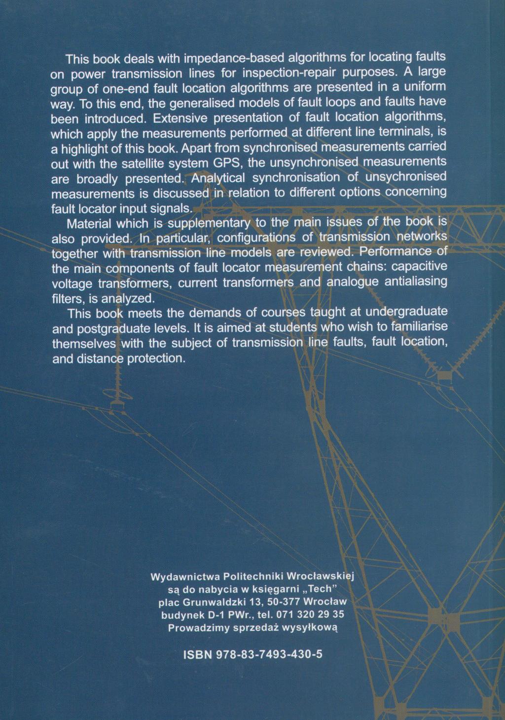
223
antenna antenna (4.139)
") .6.6 The Lmts of Usable Input Levels for LNAs The sgnal voltage level delvered to the nput of an LNA from the antenna may vary n a very wde nterval, from very weak sgnals comparable to the nose level,
.6.6 The Lmts of Usable Input Levels for LNAs The sgnal voltage level delvered to the nput of an LNA from the antenna may vary n a very wde nterval, from very weak sgnals comparable to the nose level,
High Speed ADC Sampling Transients
 Hgh Speed ADC Samplng Transents Doug Stuetzle Hgh speed analog to dgtal converters (ADCs) are, at the analog sgnal nterface, track and hold devces. As such, they nclude samplng capactors and samplng swtches.
MTBF PREDICTION REPORT
 MTBF PREDICTION REPORT PRODUCT NAME: BLE112-A-V2 Issued date: 01-23-2015 Rev:1.0 Copyrght@2015 Bluegga Technologes. All rghts reserved. 1 MTBF PREDICTION REPORT... 1 PRODUCT NAME: BLE112-A-V2... 1 1.0
Uncertainty in measurements of power and energy on power networks
 Uncertanty n measurements of power and energy on power networks E. Manov, N. Kolev Department of Measurement and Instrumentaton, Techncal Unversty Sofa, bul. Klment Ohrdsk No8, bl., 000 Sofa, Bulgara Tel./fax:
Calculation of the received voltage due to the radiation from multiple co-frequency sources
 Rec. ITU-R SM.1271-0 1 RECOMMENDATION ITU-R SM.1271-0 * EFFICIENT SPECTRUM UTILIZATION USING PROBABILISTIC METHODS Rec. ITU-R SM.1271 (1997) The ITU Radocommuncaton Assembly, consderng a) that communcatons
An Adaptive Over-current Protection Scheme for MV Distribution Networks Including DG
 An Adaptve Over-current Protecton Scheme for MV Dstrbuton Networks Includng DG S.A.M. Javadan Islamc Azad Unversty s.a.m.javadan@gmal.com M.-R. Haghfam Tarbat Modares Unversty haghfam@modares.ac.r P. Barazandeh
Application of Intelligent Voltage Control System to Korean Power Systems
 Applcaton of Intellgent Voltage Control System to Korean Power Systems WonKun Yu a,1 and HeungJae Lee b, *,2 a Department of Power System, Seol Unversty, South Korea. b Department of Power System, Kwangwoon
Research of Dispatching Method in Elevator Group Control System Based on Fuzzy Neural Network. Yufeng Dai a, Yun Du b
 2nd Internatonal Conference on Computer Engneerng, Informaton Scence & Applcaton Technology (ICCIA 207) Research of Dspatchng Method n Elevator Group Control System Based on Fuzzy Neural Network Yufeng
TECHNICAL NOTE TERMINATION FOR POINT- TO-POINT SYSTEMS TN TERMINATON FOR POINT-TO-POINT SYSTEMS. Zo = L C. ω - angular frequency = 2πf
 TECHNICAL NOTE TERMINATION FOR POINT- TO-POINT SYSTEMS INTRODUCTION Because dgtal sgnal rates n computng systems are ncreasng at an astonshng rate, sgnal ntegrty ssues have become far more mportant to
Customer witness testing guide
 Customer wtness testng gude Ths gude s amed at explanng why we need to wtness test equpment whch s beng connected to our network, what we actually do when we complete ths testng, and what you can do to
ANNUAL OF NAVIGATION 11/2006
 ANNUAL OF NAVIGATION 11/2006 TOMASZ PRACZYK Naval Unversty of Gdyna A FEEDFORWARD LINEAR NEURAL NETWORK WITH HEBBA SELFORGANIZATION IN RADAR IMAGE COMPRESSION ABSTRACT The artcle presents the applcaton
Passive Filters. References: Barbow (pp ), Hayes & Horowitz (pp 32-60), Rizzoni (Chap. 6)
, Hayes & Horowitz (pp 32-60), Rizzoni (Chap. 6)") Passve Flters eferences: Barbow (pp 6575), Hayes & Horowtz (pp 360), zzon (Chap. 6) Frequencyselectve or flter crcuts pass to the output only those nput sgnals that are n a desred range of frequences (called
Passve Flters eferences: Barbow (pp 6575), Hayes & Horowtz (pp 360), zzon (Chap. 6) Frequencyselectve or flter crcuts pass to the output only those nput sgnals that are n a desred range of frequences (called
To: Professor Avitabile Date: February 4, 2003 From: Mechanical Student Subject: Experiment #1 Numerical Methods Using Excel
 To: Professor Avtable Date: February 4, 3 From: Mechancal Student Subject:.3 Experment # Numercal Methods Usng Excel Introducton Mcrosoft Excel s a spreadsheet program that can be used for data analyss,
Figure.1. Basic model of an impedance source converter JCHPS Special Issue 12: August Page 13
 A Hgh Gan DC - DC Converter wth Soft Swtchng and Power actor Correcton for Renewable Energy Applcaton T. Selvakumaran* and. Svachdambaranathan Department of EEE, Sathyabama Unversty, Chenna, Inda. *Correspondng
Dynamic Optimization. Assignment 1. Sasanka Nagavalli January 29, 2013 Robotics Institute Carnegie Mellon University
 Dynamc Optmzaton Assgnment 1 Sasanka Nagavall snagaval@andrew.cmu.edu 16-745 January 29, 213 Robotcs Insttute Carnege Mellon Unversty Table of Contents 1. Problem and Approach... 1 2. Optmzaton wthout
A Current Differential Line Protection Using a Synchronous Reference Frame Approach
 A Current Dfferental Lne rotecton Usng a Synchronous Reference Frame Approach L. Sousa Martns *, Carlos Fortunato *, and V.Fernão res * * Escola Sup. Tecnologa Setúbal / Inst. oltécnco Setúbal, Setúbal,
Voltage Quality Enhancement and Fault Current Limiting with Z-Source based Series Active Filter
 Research Journal of Appled Scences, Engneerng and echnology 3(): 246-252, 20 ISSN: 2040-7467 Maxwell Scentfc Organzaton, 20 Submtted: July 26, 20 Accepted: September 09, 20 Publshed: November 25, 20 oltage
Performance Analysis of Multi User MIMO System with Block-Diagonalization Precoding Scheme
 Performance Analyss of Mult User MIMO System wth Block-Dagonalzaton Precodng Scheme Yoon Hyun m and Jn Young m, wanwoon Unversty, Department of Electroncs Convergence Engneerng, Wolgye-Dong, Nowon-Gu,
VRT014 User s guide V0.8. Address: Saltoniškių g. 10c, Vilnius LT-08105, Phone: (370-5) , Fax: (370-5) ,
 , Fax: (370-5) ,") VRT014 User s gude V0.8 Thank you for purchasng our product. We hope ths user-frendly devce wll be helpful n realsng your deas and brngng comfort to your lfe. Please take few mnutes to read ths manual
VRT014 User s gude V0.8 Thank you for purchasng our product. We hope ths user-frendly devce wll be helpful n realsng your deas and brngng comfort to your lfe. Please take few mnutes to read ths manual
NATIONAL RADIO ASTRONOMY OBSERVATORY Green Bank, West Virginia SPECTRAL PROCESSOR MEMO NO. 25. MEMORANDUM February 13, 1985
 NATONAL RADO ASTRONOMY OBSERVATORY Green Bank, West Vrgna SPECTRAL PROCESSOR MEMO NO. 25 MEMORANDUM February 13, 1985 To: Spectral Processor Group From: R. Fsher Subj: Some Experments wth an nteger FFT
Comparative Analysis of Reuse 1 and 3 in Cellular Network Based On SIR Distribution and Rate
 Comparatve Analyss of Reuse and 3 n ular Network Based On IR Dstrbuton and Rate Chandra Thapa M.Tech. II, DEC V College of Engneerng & Technology R.V.. Nagar, Chttoor-5727, A.P. Inda Emal: chandra2thapa@gmal.com
Unit 1. Current and Voltage U 1 VOLTAGE AND CURRENT. Circuit Basics KVL, KCL, Ohm's Law LED Outputs Buttons/Switch Inputs. Current / Voltage Analogy
 ..2 nt Crcut Bascs KVL, KCL, Ohm's Law LED Outputs Buttons/Swtch Inputs VOLTAGE AND CRRENT..4 Current and Voltage Current / Voltage Analogy Charge s measured n unts of Coulombs Current Amount of charge
IEE Electronics Letters, vol 34, no 17, August 1998, pp ESTIMATING STARTING POINT OF CONDUCTION OF CMOS GATES
 IEE Electroncs Letters, vol 34, no 17, August 1998, pp. 1622-1624. ESTIMATING STARTING POINT OF CONDUCTION OF CMOS GATES A. Chatzgeorgou, S. Nkolads 1 and I. Tsoukalas Computer Scence Department, 1 Department
Design of Shunt Active Filter for Harmonic Compensation in a 3 Phase 3 Wire Distribution Network
 Internatonal Journal of Research n Electrcal & Electroncs Engneerng olume 1, Issue 1, July-September, 2013, pp. 85-92, IASTER 2013 www.aster.com, Onlne: 2347-5439, Prnt: 2348-0025 Desgn of Shunt Actve
Dual Functional Z-Source Based Dynamic Voltage Restorer to Voltage Quality Improvement and Fault Current Limiting
 Australan Journal of Basc and Appled Scences, 5(5): 287-295, 20 ISSN 99-878 Dual Functonal Z-Source Based Dynamc Voltage Restorer to Voltage Qualty Improvement and Fault Current Lmtng M. Najaf, M. Hoseynpoor,
Simulation of Distributed Power-Flow Controller (Dpfc)
") RESEARCH INVENTY: Internatonal Journal of Engneerng and Scence ISBN: 2319-6483, ISSN: 2278-4721, Vol. 2, Issue 1 (January 2013), PP 25-32 www.researchnventy.com Smulaton of Dstrbuted Power-Flow Controller
RESEARCH INVENTY: Internatonal Journal of Engneerng and Scence ISBN: 2319-6483, ISSN: 2278-4721, Vol. 2, Issue 1 (January 2013), PP 25-32 www.researchnventy.com Smulaton of Dstrbuted Power-Flow Controller
PRACTICAL, COMPUTATION EFFICIENT HIGH-ORDER NEURAL NETWORK FOR ROTATION AND SHIFT INVARIANT PATTERN RECOGNITION. Evgeny Artyomov and Orly Yadid-Pecht
 68 Internatonal Journal "Informaton Theores & Applcatons" Vol.11 PRACTICAL, COMPUTATION EFFICIENT HIGH-ORDER NEURAL NETWORK FOR ROTATION AND SHIFT INVARIANT PATTERN RECOGNITION Evgeny Artyomov and Orly
Digital Transmission
 Dgtal Transmsson Most modern communcaton systems are dgtal, meanng that the transmtted normaton sgnal carres bts and symbols rather than an analog sgnal. The eect o C/N rato ncrease or decrease on dgtal
MASTER TIMING AND TOF MODULE-
 MASTER TMNG AND TOF MODULE- G. Mazaher Stanford Lnear Accelerator Center, Stanford Unversty, Stanford, CA 9409 USA SLAC-PUB-66 November 99 (/E) Abstract n conjuncton wth the development of a Beam Sze Montor
熊本大学学術リポジトリ. Kumamoto University Repositor
 熊本大学学術リポジトリ Kumamoto Unversty Repostor Ttle Wreless LAN Based Indoor Poston and Its Smulaton Author(s) Ktasuka, Teruak; Nakansh, Tsune CtatonIEEE Pacfc RIM Conference on Comm Computers, and Sgnal Processng
Saidi minimization of a remote distribution feeder
 Unversty of Wollongong Research nlne Faculty of Informatcs - Papers (Archve) Faculty of Engneerng and Informaton Scences 2007 Sad mnmzaton of a remote dstrbuton feeder Ka Zou Unversty of Wollongong, kz965@uow.edu.au
Network Theory. EC / EE / IN. for
 Network Theory for / / IN By www.thegateacademy.com Syllabus Syllabus for Networks Network Graphs: Matrces Assocated Wth Graphs: Incdence, Fundamental ut Set and Fundamental rcut Matrces. Soluton Methods:
Latency Insertion Method (LIM) for IR Drop Analysis in Power Grid
 for IR Drop Analysis in Power Grid") Abstract Latency Inserton Method (LIM) for IR Drop Analyss n Power Grd Dmtr Klokotov, and José Schutt-Ané Wth the steadly growng number of transstors on a chp, and constantly tghtenng voltage budgets,
Abstract Latency Inserton Method (LIM) for IR Drop Analyss n Power Grd Dmtr Klokotov, and José Schutt-Ané Wth the steadly growng number of transstors on a chp, and constantly tghtenng voltage budgets,
Research on Peak-detection Algorithm for High-precision Demodulation System of Fiber Bragg Grating
 , pp. 337-344 http://dx.do.org/10.1457/jht.014.7.6.9 Research on Peak-detecton Algorthm for Hgh-precson Demodulaton System of Fber ragg Gratng Peng Wang 1, *, Xu Han 1, Smn Guan 1, Hong Zhao and Mngle
Walsh Function Based Synthesis Method of PWM Pattern for Full-Bridge Inverter
 Walsh Functon Based Synthess Method of PWM Pattern for Full-Brdge Inverter Sej Kondo and Krt Choesa Nagaoka Unversty of Technology 63-, Kamtomoka-cho, Nagaoka 9-, JAPAN Fax: +8-58-7-95, Phone: +8-58-7-957
Section 5. Signal Conditioning and Data Analysis
 Secton 5 Sgnal Condtonng and Data Analyss 6/27/2017 Engneerng Measurements 5 1 Common Input Sgnals 6/27/2017 Engneerng Measurements 5 2 1 Analog vs. Dgtal Sgnals 6/27/2017 Engneerng Measurements 5 3 Current
Secure Transmission of Sensitive data using multiple channels
 Secure Transmsson of Senstve data usng multple channels Ahmed A. Belal, Ph.D. Department of computer scence and automatc control Faculty of Engneerng Unversty of Alexandra Alexandra, Egypt. aabelal@hotmal.com
Revision of Lecture Twenty-One
 Revson of Lecture Twenty-One FFT / IFFT most wdely found operatons n communcaton systems Important to know what are gong on nsde a FFT / IFFT algorthm Wth the ad of FFT / IFFT, ths lecture looks nto OFDM
FFT Spectrum Analyzer
 THE ANNUAL SYMPOSIUM OF THE INSTITUTE OF SOLID MECHANICS SISOM 22 BUCHAREST May 16-17 ----------------------------------------------------------------------------------------------------------------------------------------
Control of Chaos in Positive Output Luo Converter by means of Time Delay Feedback
 Control of Chaos n Postve Output Luo Converter by means of Tme Delay Feedback Nagulapat nkran.ped@gmal.com Abstract Faster development n Dc to Dc converter technques are undergong very drastc changes due
Development of a High Bandwidth, High Power Linear Amplifier for a Precision Fast Tool Servo System
 Development of a Hgh Bandwdth, Hgh Power near Amplfer for a Precson Fast Tool Servo System S. Rakuff 1, J. Cuttno 1, D. Schnstock 2 1 Dept. of Mechancal Engneerng, The Unversty of North Carolna at Charlotte,
High Speed, Low Power And Area Efficient Carry-Select Adder
 Internatonal Journal of Scence, Engneerng and Technology Research (IJSETR), Volume 5, Issue 3, March 2016 Hgh Speed, Low Power And Area Effcent Carry-Select Adder Nelant Harsh M.tech.VLSI Desgn Electroncs
A Simple Satellite Exclusion Algorithm for Advanced RAIM
 A Smple Satellte Excluson Algorthm for Advanced RAIM Juan Blanch, Todd Walter, Per Enge Stanford Unversty ABSTRACT Advanced Recever Autonomous Integrty Montorng s a concept that extends RAIM to mult-constellaton
Control Chart. Control Chart - history. Process in control. Developed in 1920 s. By Dr. Walter A. Shewhart
 Control Chart - hstory Control Chart Developed n 920 s By Dr. Walter A. Shewhart 2 Process n control A phenomenon s sad to be controlled when, through the use of past experence, we can predct, at least
Monitoring large-scale power distribution grids
 Montorng large-scale power dstrbuton grds D. Gavrlov, M. Gouzman, and S. Lury Center for Advanced Technology n Sensor Systems, Stony Brook Unversty, Stony Brook, NY 11794 Keywords: smart grd; sensor network;
The Dynamic Utilization of Substation Measurements to Maintain Power System Observability
 1 The Dynamc Utlzaton of Substaton Measurements to Mantan Power System Observablty Y. Wu, Student Member, IEEE, M. Kezunovc, Fellow, IEEE and T. Kostc, Member, IEEE Abstract-- In a power system State Estmator
Time-frequency Analysis Based State Diagnosis of Transformers Windings under the Short-Circuit Shock
 Tme-frequency Analyss Based State Dagnoss of Transformers Wndngs under the Short-Crcut Shock YUYING SHAO, ZHUSHI RAO School of Mechancal Engneerng ZHIJIAN JIN Hgh Voltage Lab Shangha Jao Tong Unversty
POLYTECHNIC UNIVERSITY Electrical Engineering Department. EE SOPHOMORE LABORATORY Experiment 1 Laboratory Energy Sources
 POLYTECHNIC UNIERSITY Electrcal Engneerng Department EE SOPHOMORE LABORATORY Experment 1 Laboratory Energy Sources Modfed for Physcs 18, Brooklyn College I. Oerew of the Experment Ths experment has three
Harmonic Balance of Nonlinear RF Circuits
 MICROWAE AND RF DESIGN Harmonc Balance of Nonlnear RF Crcuts Presented by Mchael Steer Readng: Chapter 19, Secton 19. Index: HB Based on materal n Mcrowave and RF Desgn: A Systems Approach, nd Edton, by
ECE315 / ECE515 Lecture 5 Date:
 Lecture 5 Date: 18.08.2016 Common Source Amplfer MOSFET Amplfer Dstorton Example 1 One Realstc CS Amplfer Crcut: C c1 : Couplng Capactor serves as perfect short crcut at all sgnal frequences whle blockng
Strain Gauge Measuring Amplifier BA 660
 Stran Gauge Measurng Amplfer BA 660 Orgnal of the Manual BA660 / IP20 BA660 / IP66 Table of Contents 1. Safety precautons...2 1.1. Feld of applcaton...2 1.2. Installaton...2 1.3. Mantenance...2 2. Functon...2
Research on Controller of Micro-hydro Power System Nan XIE 1,a, Dezhi QI 2,b,Weimin CHEN 2,c, Wei WANG 2,d
 Advanced Materals Research Submtted: 2014-05-13 ISSN: 1662-8985, Vols. 986-987, pp 1121-1124 Accepted: 2014-05-19 do:10.4028/www.scentfc.net/amr.986-987.1121 Onlne: 2014-07-18 2014 Trans Tech Publcatons,
Power System State Estimation Using Phasor Measurement Units
 Unversty of Kentucky UKnowledge Theses and Dssertatons--Electrcal and Computer Engneerng Electrcal and Computer Engneerng 213 Power System State Estmaton Usng Phasor Measurement Unts Jaxong Chen Unversty
Webinar Series TMIP VISION
 Webnar Seres TMIP VISION TMIP provdes techncal support and promotes knowledge and nformaton exchange n the transportaton plannng and modelng communty. DISCLAIMER The vews and opnons expressed durng ths
AFV-P 2U/4U. AC + DC Power Solutions. series. Transient Generation for Disturbance Tests. only. High Performance Programmable AC Power Source
 AFV-P seres Hgh Performance Programmable AC Power Source only 2U/4U Intutve Touch Screen HMI Output Frequency up to 15-1000Hz Power Lne Smulatons: Step & Ramp Features Fast Response Tme: 300μs AC Source
CMOS Implementation of Lossy Integrator using Current Mirrors Rishu Jain 1, Manveen Singh Chadha 2 1, 2
 Proceedngs of Natonal Conference on Recent Advances n Electroncs and Communcaton Engneerng CMOS Implementaton of Lossy Integrator usng Current Mrrors Rshu Jan, Manveen Sngh Chadha 2, 2 Department of Electroncs
Prevention of Sequential Message Loss in CAN Systems
 Preventon of Sequental Message Loss n CAN Systems Shengbng Jang Electrcal & Controls Integraton Lab GM R&D Center, MC: 480-106-390 30500 Mound Road, Warren, MI 48090 shengbng.jang@gm.com Ratnesh Kumar
Beam quality measurements with Shack-Hartmann wavefront sensor and M2-sensor: comparison of two methods
 Beam qualty measurements wth Shack-Hartmann wavefront sensor and M-sensor: comparson of two methods J.V.Sheldakova, A.V.Kudryashov, V.Y.Zavalova, T.Y.Cherezova* Moscow State Open Unversty, Adaptve Optcs
Topology Control for C-RAN Architecture Based on Complex Network
 Topology Control for C-RAN Archtecture Based on Complex Network Zhanun Lu, Yung He, Yunpeng L, Zhaoy L, Ka Dng Chongqng key laboratory of moble communcatons technology Chongqng unversty of post and telecommuncaton
Triferential Subtraction in Strain Gage Signal Conditioning. Introduction
 Trferental Subtracton n Stran Gage Sgnal Condtonng Karl F. Anderson Vald Measurements 3751 W. Ave. J-14 Lancaster, CA 93536 (661) 722-8255 http://www.vm-usa.com Introducton The general form of NASA's Anderson
Sensors for Motion and Position Measurement
 Sensors for Moton and Poston Measurement Introducton An ntegrated manufacturng envronment conssts of 5 elements:- - Machne tools - Inspecton devces - Materal handlng devces - Packagng machnes - Area where
Analysis of Time Delays in Synchronous and. Asynchronous Control Loops. Bj rn Wittenmark, Ben Bastian, and Johan Nilsson
 37th CDC, Tampa, December 1998 Analyss of Delays n Synchronous and Asynchronous Control Loops Bj rn Wttenmark, Ben Bastan, and Johan Nlsson emal: bjorn@control.lth.se, ben@control.lth.se, and johan@control.lth.se
Evaluate the Effective of Annular Aperture on the OTF for Fractal Optical Modulator
 Global Advanced Research Journal of Management and Busness Studes (ISSN: 2315-5086) Vol. 4(3) pp. 082-086, March, 2015 Avalable onlne http://garj.org/garjmbs/ndex.htm Copyrght 2015 Global Advanced Research
A NSGA-II algorithm to solve a bi-objective optimization of the redundancy allocation problem for series-parallel systems
 0 nd Internatonal Conference on Industral Technology and Management (ICITM 0) IPCSIT vol. 49 (0) (0) IACSIT Press, Sngapore DOI: 0.776/IPCSIT.0.V49.8 A NSGA-II algorthm to solve a b-obectve optmzaton of
A Novel Soft-Switching Two-Switch Flyback Converter with a Wide Operating Range and Regenerative Clamping
 77 Journal of ower Electroncs, ol 9, No 5, September 009 JE 9-5- A Novel Soft-Swtchng Two-Swtch Flybac Converter wth a Wde Operatng Range and Regeneratve Clampng Marn-Go Km and Young-Seo Jung * Dvson of
Shunt Active Filters (SAF)
") EN-TH05-/004 Martt Tuomanen (9) Shunt Actve Flters (SAF) Operaton prncple of a Shunt Actve Flter. Non-lnear loads lke Varable Speed Drves, Unnterrupted Power Supples and all knd of rectfers draw a non-snusodal
EN-TH05-/004 Martt Tuomanen (9) Shunt Actve Flters (SAF) Operaton prncple of a Shunt Actve Flter. Non-lnear loads lke Varable Speed Drves, Unnterrupted Power Supples and all knd of rectfers draw a non-snusodal
A High-Sensitivity Oversampling Digital Signal Detection Technique for CMOS Image Sensors Using Non-destructive Intermediate High-Speed Readout Mode
 A Hgh-Senstvty Oversamplng Dgtal Sgnal Detecton Technque for CMOS Image Sensors Usng Non-destructve Intermedate Hgh-Speed Readout Mode Shoj Kawahto*, Nobuhro Kawa** and Yoshak Tadokoro** *Research Insttute
Rejection of PSK Interference in DS-SS/PSK System Using Adaptive Transversal Filter with Conditional Response Recalculation
 SERBIAN JOURNAL OF ELECTRICAL ENGINEERING Vol., No., November 23, 3-9 Rejecton of PSK Interference n DS-SS/PSK System Usng Adaptve Transversal Flter wth Condtonal Response Recalculaton Zorca Nkolć, Bojan
Comparison of Reference Compensating Current Estimation Techniques for Shunt Active Filter
 Comparson of Reference Compensatng Current Estmaton Technques for Shunt Acte Flter R.SHANMUGHA SUNDARAM K.J.POORNASEVAN N.DEVARAJAN Department of Electrcal & Electroncs Engneerng Goernment College of Technology
1 GSW Multipath Channel Models
 In the general case, the moble rado channel s pretty unpleasant: there are a lot of echoes dstortng the receved sgnal, and the mpulse response keeps changng. Fortunately, there are some smplfyng assumptons
A Comparison of Two Equivalent Real Formulations for Complex-Valued Linear Systems Part 2: Results
 AMERICAN JOURNAL OF UNDERGRADUATE RESEARCH VOL. 1 NO. () A Comparson of Two Equvalent Real Formulatons for Complex-Valued Lnear Systems Part : Results Abnta Munankarmy and Mchael A. Heroux Department of
Chaotic Filter Bank for Computer Cryptography
 Chaotc Flter Bank for Computer Cryptography Bngo Wng-uen Lng Telephone: 44 () 784894 Fax: 44 () 784893 Emal: HTwng-kuen.lng@kcl.ac.ukTH Department of Electronc Engneerng, Dvson of Engneerng, ng s College
Optimal Placement of PMU and RTU by Hybrid Genetic Algorithm and Simulated Annealing for Multiarea Power System State Estimation
 T. Kerdchuen and W. Ongsakul / GMSARN Internatonal Journal (09) - Optmal Placement of and by Hybrd Genetc Algorthm and Smulated Annealng for Multarea Power System State Estmaton Thawatch Kerdchuen and
D-STATCOM Optimal Allocation Based On Investment Decision Theory
 Internatonal Conference on Computer Engneerng, Informaton Scence & Applcaton Technology (ICCIA 2016) D-STATCOM Optmal Allocaton Based On Investment Decson Theory Yongjun Zhang1, a, Yfu Mo1, b and Huazhen
Safety and resilience of Global Baltic Network of Critical Infrastructure Networks related to cascading effects
 Blokus-Roszkowska Agneszka Dzula Przemysław Journal of Polsh afety and Relablty Assocaton ummer afety and Relablty emnars, Volume 9, Number, Kołowrock Krzysztof Gdyna Martme Unversty, Gdyna, Poland afety
FAST IMPEDANCE SPECTROSCOPY METHOD USING SQUARE PULSE EXCITATION
 2th IMEKO TC & TC7 Jont Symposum on Man Scence & Measurement September, 3 5, 2008, Annecy, France FAST IMPEDANCE SPECTROSCOPY METHOD USING SQUARE PULSE EXCITATION Jerzy Hoja, Grzegorz Lentka 2 Gdansk Unversty
Adaptive System Control with PID Neural Networks
 Adaptve System Control wth PID Neural Networs F. Shahra a, M.A. Fanae b, A.R. Aromandzadeh a a Department of Chemcal Engneerng, Unversty of Sstan and Baluchestan, Zahedan, Iran. b Department of Chemcal
SMALL POWER GENERATOR FOR WIND POWER PLANTS
 Zeszyty Problemowe Maszyny Elektryczne Nr 8/29 9 Karel hmelík, Stanslav Mšák Techncal Unversty of Ostrava, Ostrava SMALL POWER GENERATOR FOR WND POWER PLANTS GENERATORY MAŁEJ MOY DO ELEKTROWN WATROWYH
A Facts Device: Distributed Power-Flow Controller (DPFC)
") A Facts Devce: Dstrbuted Power-Flow Controller (DPFC) Guda Pryanka 1, K. Jaghannath 2, D. Kumara Swamy 3 1, 2, 3 Dept. of EEE, SVS Insttute of Technology, Hanamkonda, T.S, Inda Emal address: ujjwalak32@gmal.com
A Facts Devce: Dstrbuted Power-Flow Controller (DPFC) Guda Pryanka 1, K. Jaghannath 2, D. Kumara Swamy 3 1, 2, 3 Dept. of EEE, SVS Insttute of Technology, Hanamkonda, T.S, Inda Emal address: ujjwalak32@gmal.com
Micro-grid Inverter Parallel Droop Control Method for Improving Dynamic Properties and the Effect of Power Sharing
 2015 AASRI Internatonal Conference on Industral Electroncs and Applcatons (IEA 2015) Mcro-grd Inverter Parallel Droop Control Method for Improvng Dynamc Propertes and the Effect of Power Sharng aohong
Efficient Large Integers Arithmetic by Adopting Squaring and Complement Recoding Techniques
 The th Worshop on Combnatoral Mathematcs and Computaton Theory Effcent Large Integers Arthmetc by Adoptng Squarng and Complement Recodng Technques Cha-Long Wu*, Der-Chyuan Lou, and Te-Jen Chang *Department
Fault resistance sensitivity of sparse measurement based transmission line fault location
 ault resstance senstvty of sparse measurement based transmsson lne fault locaton Papya Dutta Dept. of Electrcal and Computer Engneerng Texas A & M Unversty College Staton, TX, USA papya8@tamu.edu Abstract
The Performance Improvement of BASK System for Giga-Bit MODEM Using the Fuzzy System
 Int. J. Communcatons, Network and System Scences, 10, 3, 1-5 do:10.36/jcns.10.358 Publshed Onlne May 10 (http://www.scrp.org/journal/jcns/) The Performance Improvement of BASK System for Gga-Bt MODEM Usng
Graph Method for Solving Switched Capacitors Circuits
 Recent Advances n rcuts, ystems, gnal and Telecommuncatons Graph Method for olvng wtched apactors rcuts BHUMIL BRTNÍ Department of lectroncs and Informatcs ollege of Polytechncs Jhlava Tolstého 6, 586
ITU-T O.172. Amendment 1 (06/2008)
") Internatonal Telecommuncaton Unon ITU-T O.72 TELECOMMUNICATION STANDARDIZATION SECTOR OF ITU Amendment (6/8) SERIES O: SPECIFICATIONS OF MEASURING EQUIPMENT Equpment for the measurement of dgtal and analogue/dgtal
Internatonal Telecommuncaton Unon ITU-T O.72 TELECOMMUNICATION STANDARDIZATION SECTOR OF ITU Amendment (6/8) SERIES O: SPECIFICATIONS OF MEASURING EQUIPMENT Equpment for the measurement of dgtal and analogue/dgtal
Location of Single Line-to-Ground Faults on Distribution Feeders Using Voltage Measurements
 1 Locaton of Sngle e-to-ground Faults on Dstrbuton Feeders Usng Voltage Measurements R. A. F. Perera, Student Member, EEE, L. G. W. da Slva, M. Kezunovc, Fellow, EEE, and J. R. S. Mantovan, Member, EEE
Digital Differential Protection of Power Transformer Using Matlab
 Chapter 10 Dgtal Dfferental Protecton of Power Transformer Usng Matlab Adel Aktab and M. Azzur Rahman Addtonal nformaton s avalable at the end of the chapter http://dx.do.org/10.5772/48624 1. Introducton
Fast Code Detection Using High Speed Time Delay Neural Networks
 Fast Code Detecton Usng Hgh Speed Tme Delay Neural Networks Hazem M. El-Bakry 1 and Nkos Mastoraks 1 Faculty of Computer Scence & Informaton Systems, Mansoura Unversty, Egypt helbakry0@yahoo.com Department
Guidelines for CCPR and RMO Bilateral Key Comparisons CCPR Working Group on Key Comparison CCPR-G5 October 10 th, 2014
 Gudelnes for CCPR and RMO Blateral Key Comparsons CCPR Workng Group on Key Comparson CCPR-G5 October 10 th, 2014 These gudelnes are prepared by CCPR WG-KC and RMO P&R representatves, and approved by CCPR,
Test 2. ECON3161, Game Theory. Tuesday, November 6 th
 Test 2 ECON36, Game Theory Tuesday, November 6 th Drectons: Answer each queston completely. If you cannot determne the answer, explanng how you would arrve at the answer may earn you some ponts.. (20 ponts)
ECE 2133 Electronic Circuits. Dept. of Electrical and Computer Engineering International Islamic University Malaysia
 ECE 2133 Electronc Crcuts Dept. of Electrcal and Computer Engneerng Internatonal Islamc Unversty Malaysa Chapter 12 Feedback and Stablty Introducton to Feedback Introducton to Feedback 1-4 Harold Black,
Ultra Sonic Flow Rate Measurements in Large Pipes and open Channels
 Ultra Sonc Flow Rate Measurements n Large Ppes and open Channels Dr. Mchael Teufel I Summary Correlaton s a mathematcal tool whch, enabled by developments of fast and powerful mcroprocessors n last few
Optimal Allocation of Static VAr Compensator for Active Power Loss Reduction by Different Decision Variables
 S. Aucharyamet and S. Srsumrannukul / GMSARN Internatonal Journal 4 (2010) 57-66 Optmal Allocaton of Statc VAr Compensator for Actve Power oss Reducton by Dfferent Decson Varables S. Aucharyamet and S.
Network Reconfiguration in Distribution Systems Using a Modified TS Algorithm
 Network Reconfguraton n Dstrbuton Systems Usng a Modfed TS Algorthm ZHANG DONG,FU ZHENGCAI,ZHANG LIUCHUN,SONG ZHENGQIANG School of Electroncs, Informaton and Electrcal Engneerng Shangha Jaotong Unversty
Design of Teaching Platform Based on Information Detection System
 , pp.43-48 http://dx.do.org/1.14257/astl.216.139.8 Desgn of Teachng Platform Based on Informaton Detecton System Zhenjng Yao, Lxn L, Qn Gao & Zhmng Han Insttute of Dsaster Preventon Sanhe, Hebe, People
Implementation of Fan6982 Single Phase Apfc with Analog Controller
 Internatonal Journal of Research n Engneerng and Scence (IJRES) ISSN (Onlne): 2320-9364, ISSN (Prnt): 2320-9356 Volume 5 Issue 7 ǁ July. 2017 ǁ PP. 01-05 Implementaton of Fan6982 Sngle Phase Apfc wth Analog
THE ARCHITECTURE OF THE BROADBAND AMPLIFIERS WITHOUT CLASSICAL STAGES WITH A COMMON BASE AND A COMMON EMITTER
 VOL. 0, NO. 8, OCTOBE 205 ISSN 89-6608 2006-205 Asan esearch Publshng Network (APN. All rghts reserved. THE ACHITECTUE OF THE BOADBAND AMPLIFIES WITHOUT CLASSICAL STAGES WITH A COMMON BASE AND A COMMON
Introduction. (Received 08 January 2009; accepted 10 March 2009)
") 44. Creatng of the mathematcal model of a reslent support sprng type element and ts transfer functon from the nput and output mpulse responses V. Slvnskas, K. Slvnskas, A. Trumpa Vlnus Gedmnas Techncal
44. Creatng of the mathematcal model of a reslent support sprng type element and ts transfer functon from the nput and output mpulse responses V. Slvnskas, K. Slvnskas, A. Trumpa Vlnus Gedmnas Techncal
CONCERNING THE NO LOAD HIGH VOLTAGE TRANSFORMERS DISCONNECTING
 CONCERNING THE NO LOAD HIGH VOLTAGE TRANSFORMERS DISCONNEING Mara D Brojbou and Vrgna I Ivanov Faculty o Electrcal engneerng Unversty o Craova, 7 Decebal Blv, Craova, Romana E-mal: mbrojbou@elthucvro,
The Impact of Spectrum Sensing Frequency and Packet- Loading Scheme on Multimedia Transmission over Cognitive Radio Networks
 Ths artcle has been accepted for publcaton n a future ssue of ths journal, but has not been fully edted. Content may change pror to fnal publcaton. The Impact of Spectrum Sensng Frequency and Pacet- Loadng