EEG Probe Project. Grant G. Connell
|
|
|
- Spencer Watts
- 6 years ago
- Views:
Transcription
1 EEG Probe Project Grant G. Connell
2 EEG Probe Project Design Objectives Investigate BCI for severely handicapped individuals Use time, frequency, and phase displays Use DSP techniques for near real time responses Use only the mono input to the sound card of a PC for multiple channel displays (start with two channels)
3 EEG Probe Project Design requirements Some compatibility with Modular EEG H/W Can use analog section with modulator section, +/- 5V operation Single input (mono to sound card) Two channel prototype, expandable to 32 channels Reference leg for both channels Select either SSB, AM, or FM modulation technique Selected AM for frequency stability, better spectrum management than FM Displays Stripline, Vertical FFT, Vertical Phase, Waterfall Application screen size = 1024 by 768
4 EEG Probe Project System Design (AM Modulation) Amplitude 12 khz 14 khz 16 khz 18 khz (Carriers) 500 Hz Chan1 Chan2 Chan3 Chan4 Freq (Hz)
5 EEG Probe Project AM System Design, Processing Chain Stripchart Mic. Sound Card Input (Mono) Hz Sampling Rate 1024 Byte Blocks Channel 1 Bandpass Filter, 16 khz Channel 2 Bandpass Filter, 18 khz 1024 Byte Convolutional Filter, 500 Hz BW Channel 1 AM Demod and LP Filter Channel 2 AM Demod and LP Filter 1024 Bytes Envelope Detection Decimate (8x) Prog. Filter, DC Removal Decimate (8x) Prog Filter, DC Removal 128 Bytes Channel Byte Buffer & FFT Channel Byte Buffer & FFT 1024 Bytes Vertical FFT, Phase Vertical FFT, Phase Stripchart
6 EEG Probe Project System Design: Displays Vertical FFT Vertical Phase Strip Chart Waterfall
7 EEG Probe Project Development Environment Use C,C++ Builder IDE (from Borland) Third party components (knobs, switches) Low level sound card drivers All software developed internally Could use Intel DSP library for open source development
8 Vertical FFT Display, 6 Hz and 12 Hz inputs

9 EEG Probe Project Vertical Phase Display, 2 Hz and 5 Hz

10 Waterfall Display, 6 Hz and 12 Hz inputs

11 RAW FFT Spectrum 3.5 khz and 4.0 khz carriers
12 Alpha Bursts, 9 Hz
13 EEG Probe Project First Hardware Protype Two PC boards Dual channel analog design similar to Modular EEG Dual channel modulator board using low cost ICs, output transformer coupled for isolation from the PC Single supply input (+12 volt) from isolation transformer, converted to +/- 5 volts. Front panel gain control for each channel Power supply LEDs
14 EEG Probe Project Hardware Block Diagram Lo1 Chan 1 Chan 1 Ref Gain Gain AM Mod AM Mod Sum XFMR To PC DRL Gnd Lo2 Dual Channel Low Noise Amplifier Board Dual Channel AM Modulator Board

15 Breadboard Designs New Designs AM Design FM Design

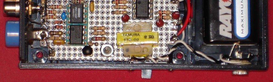
16 Prototype Unit

17 Chassis Layout Power Supply Modulator Board Dual Amp Board
18 EEG Probe Project FM System Design, Processing Chain Stripchart Sound Card Input (Mono) Hz Sampling Rate 1024 Byte Blocks Channel 1 Bandpass Filter, 14 khz Channel 2 Bandpass Filter, 19 khz 4096 Byte Convolutional Filter, 500 Hz BW Channel 1 FM Demod and LP Filter Channel 2 FM Demod and LP Filter 4096 Bytes Envelope Detection Decimate (32x) Prog. Filter, DC Removal Decimate (32x) Prog Filter, DC Removal 128 Bytes Channel Byte Buffer & FFT Channel Byte Buffer & FFT 1024 Bytes Vertical FFT, Phase Vertical FFT, Phase Stripchart

19 Dual Channel FM Spectrum

20 Dual Channel FM Waveforms
21 Modulation Scheme Comparison AM Modulation Good spectrum management (1500 Hz per channel) 80 db dynamic range (2.0 mv to 0.20 uv) Requires only 3 IC s plus a transistor per channel (most recent design) Gain calibration procedure with sound card required 60 db cross-talk isolation between channels FM Modulation Limited spectrum management (4 khz per channel) 80 db dynamic range (1.5 mv to 0.15 uv) Requires only 3 IC s per channel Gain calibration built-in via H/W and S/W design 60 db cross-talk isolation between channels
22 EEG Probe Project Prototyped single channel AM modulation unit Current drain approximately volts Prototype dual channel FM modulation unit Current drain approximately volts Switched to CMOS version of NE555 IC Prototype dual channel AM modulation unit Current drain approximately volts Switched to simpler AM modulator with better noise performance Used CMOS version of NE555 IC (ICM7555) All prototypes completed and operational

23 Single Channel AM Unit

24 Dual Channel FM Unit

25 Dual Channel AM Unit
26 EEG Probe Project Current Status Completing final S/W application AM demodulation design complete FM demodulation design complete Added adjustable LP and BP filters (S/W) Switched to digital LO (for a two channel system only), used cheaper ICs to generate the local oscillator Dual channel AM and FM designs completed and prototypes built
27 Software Update EEG Probe software Added record and playback capability Near real-time response with IIR digital filters Sound Card Interface to NeuroServer Converts sound card data to EDF format and interfaces to the NeuroServer Also converts sound card data to ModEEG format for RS- 232 interfaces, requires Eltima virtual RS-232 driver Both software packages available at the SourceForge web site:
Exercise 2: FM Detection With a PLL
 Phase-Locked Loop Analog Communications Exercise 2: FM Detection With a PLL EXERCISE OBJECTIVE When you have completed this exercise, you will be able to explain how the phase detector s input frequencies
Experiment One: Generating Frequency Modulation (FM) Using Voltage Controlled Oscillator (VCO)
 Using Voltage Controlled Oscillator (VCO)") Experiment One: Generating Frequency Modulation (FM) Using Voltage Controlled Oscillator (VCO) Modified from original TIMS Manual experiment by Mr. Faisel Tubbal. Objectives 1) Learn about VCO and how
Experiment One: Generating Frequency Modulation (FM) Using Voltage Controlled Oscillator (VCO) Modified from original TIMS Manual experiment by Mr. Faisel Tubbal. Objectives 1) Learn about VCO and how
RF/IF Terminology and Specs
 RF/IF Terminology and Specs Contributors: Brad Brannon John Greichen Leo McHugh Eamon Nash Eberhard Brunner 1 Terminology LNA - Low-Noise Amplifier. A specialized amplifier to boost the very small received
OBJECTIVES EQUIPMENT LIST
 1 Reception of Amplitude Modulated Signals AM Demodulation OBJECTIVES The purpose of this experiment is to show how the amplitude-modulated signals are demodulated to obtain the original signal. Also,
Berkeley Nucleonics Corporation
 Berkeley Nucleonics Corporation A trusted source for quality and innovative instrumentation since 1963 Test And Measurement Nuclear Expertise RF/Microwave BNC at Our Core BNC Mission: Providing our customers
1. General Outline Project Proposal April 9, 2014 Kayla Esquivel and Jason Yang
 1. General Outline 6.101 Project Proposal April 9, 2014 Kayla Esquivel and Jason Yang The invention and mass application of radio broadcast was triggered in the first decade of the nineteenth century by
Technician License Course Chapter 3 Types of Radios and Radio Circuits. Module 7
 Technician License Course Chapter 3 Types of Radios and Radio Circuits Module 7 Radio Block Diagrams Radio Circuits can be shown as functional blocks connected together. Knowing the description of common
Variable Gm Calibration Procedure
 Variable Gm Calibration Procedure REV. 3 Sept. 16, 2018. Warm-up Power on the unit and let it warm for about 20-30 minutes, so that all circuitries stabilize. A.C. Check With a DMM (Digital Multi Meter)
Exercise 1: Frequency and Phase Modulation
 Exercise 1: Frequency and Phase Modulation EXERCISE OBJECTIVE When you have completed this exercise, you will be able to describe frequency modulation and an FM circuit. You will also be able to describe
SIGNAL RECOVERY. Model 7265 DSP Lock-in Amplifier
 Model 7265 DSP Lock-in Amplifier FEATURES 0.001 Hz to 250 khz operation Voltage and current mode inputs Direct digital demodulation without down-conversion 10 µs to 100 ks output time constants Quartz
Hardware Architecture of Software Defined Radio (SDR)
") Hardware Architecture of Software Defined Radio (SDR) Tassadaq Hussain Assistant Professor: Riphah International University Research Collaborations: Microsoft Barcelona Supercomputing Center University
Hardware Architecture of Software Defined Radio (SDR) Tassadaq Hussain Assistant Professor: Riphah International University Research Collaborations: Microsoft Barcelona Supercomputing Center University
Exercise 1: Amplitude Modulation
 AM Transmission Analog Communications Exercise 1: Amplitude Modulation EXERCISE OBJECTIVE When you have completed this exercise, you will be able to describe the generation of amplitudemodulated signals
HF Receivers, Part 2
 HF Receivers, Part 2 Superhet building blocks: AM, SSB/CW, FM receivers Adam Farson VA7OJ View an excellent tutorial on receivers NSARC HF Operators HF Receivers 2 1 The RF Amplifier (Preamp)! Typical
Feedback Loop Canceller Circuit
 Feedback Loop Canceller Circuit Bachelor Thesis Ahmad Bader Ibrahim Obeidat Supervised by Prof. Dr.-Ing. Klaus Solbach 17.11.2014 Outline: 1 Motivation 2 Circuit description 3 Tasks and objectives 4 Active
TS9080. microgen. electronics TM. FM Modulation and AF Spectrum Analyser Technical specification Issue 1.3.
 TS9080 www.microgenelectronics.com FM Modulation and AF Spectrum Analyser 2009 Technical specification Issue 1.3 The TS9080, FM Modulation and AF Spectrum Analyser, has been designed for precision monitoring
INTEGRATED CIRCUITS. AN145 NE5517/A transconductance amplifier applications Dec
 INTEGRATED CIRCUITS NE5517/A transconductance amplifier applications 1988 Dec Application note DESCRIPTION The Philips Semiconductors NE5517 is a truly versatile dual operational transconductance amplifier.
Analog Synthesizer: Functional Description
 Analog Synthesizer: Functional Description Documentation and Technical Information Nolan Lem (2013) Abstract This analog audio synthesizer consists of a keyboard controller paired with several modules
PC-OSCILLOSCOPE PCS500. Analog and digital circuit sections. Description of the operation
 PC-OSCILLOSCOPE PCS500 Analog and digital circuit sections Description of the operation Operation of the analog section This description concerns only channel 1 (CH1) input stages. The operation of CH2
6.101 Project Proposal April 9, 2014 Kayla Esquivel and Jason Yang. General Outline
 6.101 Project Proposal April 9, 2014 Kayla Esquivel and Jason Yang General Outline We will build a superheterodyne AM Radio Receiver circuit that will have a bandwidth of the entire AM spectrum, and whose
FM Modulation. Accuracy. Total. Harmonics. Input Range. Frequency. Range. Deviation. Range. Modulation. Accuracy. Audio In Switchable Loads.
 Product Specification VIAVI 3550R Touch-Screen Radio Test System VIAVI Solutions General Specifications RF Signal Generator Output SSB Phase Noise 2 MHz - 1 GHz (usable from 500 khz) T/R Port: -50 to -125
CLOUDSDR RFSPACE #CONNECTED SOFTWARE DEFINED RADIO. final design might vary without notice
 CLOUDSDR #CONNECTED SOFTWARE DEFINED RADIO final design might vary without notice 1 - PRELIMINARY SPECIFICATIONS http://www.rfspace.com v0.1 RFSPACE CloudSDR CLOUDSDR INTRODUCTION The RFSPACE CloudSDR
Analog Arts SL987 SL957 SL937 SL917 Product Specifications [1]
![Analog Arts SL987 SL957 SL937 SL917 Product Specifications [1]](/thumbs/95/126095980.jpg "Analog Arts SL987 SL957 SL937 SL917 Product Specifications [1]") www.analogarts.com Analog Arts SL987 SL957 SL937 SL917 Product Specifications [1] 1. These models include: an oscilloscope, a spectrum analyzer, a data recorder, a frequency & phase meter, an arbitrary
www.analogarts.com Analog Arts SL987 SL957 SL937 SL917 Product Specifications [1] 1. These models include: an oscilloscope, a spectrum analyzer, a data recorder, a frequency & phase meter, an arbitrary
FREQUENCY AGILE FM MODULATOR INSTRUCTION BOOK IB
 FMT615C FREQUENCY AGILE FM MODULATOR INSTRUCTION BOOK IB1215-02 TABLE OF CONTENTS SECTION SUBJECT 1.0 Introduction 2.0 Installation & Operating Instructions 3.0 Specification 4.0 Functional Description
LumiDax Electronics LLC Bakerboard Analog Trainer. Operator's Guide with Example Projects
 LumiDax Electronics LLC Bakerboard Analog Trainer Operator's Guide with Example Projects Written by Jonathan Baumgardner Copyright 2014 Introduction The LumiDax Bakerboard Analog Trainer is an all-in-one
EE470 Electronic Communication Theory Exam II
 EE470 Electronic Communication Theory Exam II Open text, closed notes. For partial credit, you must show all formulas in symbolic form and you must work neatly!!! Date: November 6, 2013 Name: 1. [16%]
Analog Arts SG985 SG884 SG834 SG814 Product Specifications [1]
![Analog Arts SG985 SG884 SG834 SG814 Product Specifications [1]](/thumbs/94/122371203.jpg "Analog Arts SG985 SG884 SG834 SG814 Product Specifications [1]") www.analogarts.com Analog Arts SG985 SG884 SG834 SG814 Product Specifications [1] 1. These models include: an oscilloscope, a spectrum analyzer, a data recorder, a frequency & phase meter, and an arbitrary
www.analogarts.com Analog Arts SG985 SG884 SG834 SG814 Product Specifications [1] 1. These models include: an oscilloscope, a spectrum analyzer, a data recorder, a frequency & phase meter, and an arbitrary
Analog Arts SF990 SF880 SF830 Product Specifications
 1 www.analogarts.com Analog Arts SF990 SF880 SF830 Product Specifications Analog Arts reserves the right to change, modify, add or delete portions of any one of its specifications at any time, without
TS9085. microgen. electronics TM. FM Modulation and AF Spectrum Analyser Technical specification Issue
 TS9085 www.microgenelectronics.com FM Modulation and AF Spectrum Analyser 2009 Technical specification Issue 1.2 The TS9085, FM Modulation and AF Spectrum Analyser, has been designed for precision monitoring
Session 3. CMOS RF IC Design Principles
 Session 3 CMOS RF IC Design Principles Session Delivered by: D. Varun 1 Session Topics Standards RF wireless communications Multi standard RF transceivers RF front end architectures Frequency down conversion
Appendix B. Design Implementation Description For The Digital Frequency Demodulator
 Appendix B Design Implementation Description For The Digital Frequency Demodulator The DFD design implementation is divided into four sections: 1. Analog front end to signal condition and digitize the
Software Defined Radio for Beginners
 Software Defined Radio for Beginners July 19, 2014 Stephen Hicks, N5AC SDRs for Beginners Agenda What is an SDR? History of Amateur SDR Technologies that make an SDR Examples of SDRs Benefits and uses
ericssonz LBI-38640E MAINTENANCE MANUAL FOR VHF TRANSMITTER SYNTHESIZER MODULE 19D902780G1 DESCRIPTION
 MAINTENANCE MANUAL FOR VHF TRANSMITTER SYNTHESIZER MODULE 19D902780G1 TABLE OF CONTENTS Page DESCRIPTION........................................... Front Cover GENERAL SPECIFICATIONS...................................
Exercise 1: RF Stage, Mixer, and IF Filter
 SSB Reception Analog Communications Exercise 1: RF Stage, Mixer, and IF Filter EXERCISE OBJECTIVE DISCUSSION On the circuit board, you will set up the SSB transmitter to transmit a 1000 khz SSB signal
EE 3302 LAB 1 EQIUPMENT ORIENTATION
 EE 3302 LAB 1 EQIUPMENT ORIENTATION Pre Lab: Calculate the theoretical gain of the 4 th order Butterworth filter (using the formula provided. Record your answers in Table 1 before you come to class. Introduction:
Exercise 2: Demodulation (Quadrature Detector)
") Analog Communications Angle Modulation and Demodulation Exercise 2: Demodulation (Quadrature Detector) EXERCISE OBJECTIVE When you have completed this exercise, you will be able to explain demodulation
Analog Communications Angle Modulation and Demodulation Exercise 2: Demodulation (Quadrature Detector) EXERCISE OBJECTIVE When you have completed this exercise, you will be able to explain demodulation
Universitas Sumatera Utara
 Amplitude Shift Keying & Frequency Shift Keying Aim: To generate and demodulate an amplitude shift keyed (ASK) signal and a binary FSK signal. Intro to Generation of ASK Amplitude shift keying - ASK -
Analog Arts SF900 SF650 SF610 Product Specifications
 www.analogarts.com Analog Arts SF900 SF650 SF610 Product Specifications Analog Arts reserves the right to change, modify, add or delete portions of any one of its specifications at any time, without prior
Experiment No. 3 Pre-Lab Phase Locked Loops and Frequency Modulation
 Experiment No. 3 Pre-Lab Phase Locked Loops and Frequency Modulation The Pre-Labs are informational and although they follow the procedures in the experiment, they are to be completed outside of the laboratory.
EE-4022 Experiment 3 Frequency Modulation (FM)
") EE-4022 MILWAUKEE SCHOOL OF ENGINEERING 2015 Page 3-1 Student Objectives: EE-4022 Experiment 3 Frequency Modulation (FM) In this experiment the student will use laboratory modules including a Voltage-Controlled
EE-4022 MILWAUKEE SCHOOL OF ENGINEERING 2015 Page 3-1 Student Objectives: EE-4022 Experiment 3 Frequency Modulation (FM) In this experiment the student will use laboratory modules including a Voltage-Controlled
Total No. of Questions : 40 ] [ Total No. of Printed Pages : 7. March, Time : 3 Hours 15 Minutes ] [ Max. Marks : 90
![Total No. of Questions : 40 ] [ Total No. of Printed Pages : 7. March, Time : 3 Hours 15 Minutes ] [ Max. Marks : 90](/thumbs/93/111664408.jpg "Total No. of Questions : 40 ] [ Total No. of Printed Pages : 7. March, Time : 3 Hours 15 Minutes ] [ Max. Marks : 90") Code No. 40 Total No. of Questions : 40 ] [ Total No. of Printed Pages : 7 March, 2009 ELECTRONICS Time : 3 Hours 15 Minutes ] [ Max. Marks : 90 Note : i) The question paper has four Parts A, B, C & D.
Code No. 40 Total No. of Questions : 40 ] [ Total No. of Printed Pages : 7 March, 2009 ELECTRONICS Time : 3 Hours 15 Minutes ] [ Max. Marks : 90 Note : i) The question paper has four Parts A, B, C & D.
Software Defined Radios
 Software Defined Radios What Is the SDR Radio? An SDR in general is a radio that has: Primary Functionality [modulation and demodulation, filtering, etc.] defined in software. DSP algorithms implemented
Cornerstone Electronics Technology and Robotics Week 21 Electricity & Electronics Section 10.5, Oscilloscope
 Cornerstone Electronics Technology and Robotics Week 21 Electricity & Electronics Section 10.5, Oscilloscope Field trip to Deerhaven Generation Plant: Administration: o Prayer o Turn in quiz Electricity
Recap of Last 2 Classes
 Recap of Last 2 Classes Transmission Media Analog versus Digital Signals Bandwidth Considerations Attentuation, Delay Distortion and Noise Nyquist and Shannon Analog Modulation Digital Modulation What
Experiment 02: Amplitude Modulation
 ECE316, Experiment 02, 2017 Communications Lab, University of Toronto Experiment 02: Amplitude Modulation Bruno Korst - bkf@comm.utoronto.ca Abstract In this second laboratory experiment, you will see
Radio Receivers. Al Penney VO1NO
 Radio Receivers Al Penney VO1NO Role of the Receiver The Antenna must capture the radio wave. The desired frequency must be selected from all the EM waves captured by the antenna. The selected signal is
High performance low power mixer FM IF system
 DESCRIPTION The is a high performance monolithic low-power FM IF system incorporating a mixer/oscillator, two limiting intermediate frequency amplifiers, quadrature detector, muting, logarithmic received
multiplier input Env. Det. LPF Y (Vertical) VCO X (Horizontal)
 VCO X (Horizontal)") Spectrum Analyzer Objective: The aim of this project is to realize a spectrum analyzer using analog circuits and a CRT oscilloscope. This interface circuit will enable to use oscilloscopes as spectrum
Spectrum Analyzer Objective: The aim of this project is to realize a spectrum analyzer using analog circuits and a CRT oscilloscope. This interface circuit will enable to use oscilloscopes as spectrum
Spectrum analyzer for frequency bands of 8-12, and MHz
 EE389 Electronic Design Lab Project Report, EE Dept, IIT Bombay, November 2006 Spectrum analyzer for frequency bands of 8-12, 12-16 and 16-20 MHz Group No. D-13 Paras Choudhary (03d07012)
GOVERNMENT OF KARNATAKA KARNATAKA STATE PRE-UNIVERSITY EDUCATION EXAMINATION BOARD II YEAR PUC EXAMINATION JULY-2012 SCHEME OF VALUATION
 GOVERNMENT OF KARNATAKA KARNATAKA STATE PRE-UNIVERSITY EDUCATION EXAMINATION BOARD II YEAR PUC EXAMINATION JULY-0 SCHEME OF VALUATION Subject Code: 40 Subject: PART - A 0. Which region of the transistor
EECS 307: Lab Handout 2 (FALL 2012)
") EECS 307: Lab Handout 2 (FALL 2012) I- Audio Transmission of a Single Tone In this part you will modulate a low-frequency audio tone via AM, and transmit it with a carrier also in the audio range. The
EECS 307: Lab Handout 2 (FALL 2012) I- Audio Transmission of a Single Tone In this part you will modulate a low-frequency audio tone via AM, and transmit it with a carrier also in the audio range. The
Twelve voice signals, each band-limited to 3 khz, are frequency -multiplexed using 1 khz guard bands between channels and between the main carrier
 Twelve voice signals, each band-limited to 3 khz, are frequency -multiplexed using 1 khz guard bands between channels and between the main carrier and the first channel. The modulation of the main carrier
ERICSSONZ LBI-39123A. MAINTENANCE MANUAL FOR 21.4 MHz RECEIVER IF MODULE 12.5/25 khz CHANNEL SPACING 19D902783G7 DESCRIPTION TABLE OF CONTENTS
 A MAINTENANCE MANUAL FOR 21.4 MHz 12.5/25 khz CHANNEL SPACING 19D902783G7 TABLE OF CONTENTS Page DESCRIPTION............................................ Front Cover GENERAL SPECIFICATIONS....................................
AC LAB ECE-D ecestudy.wordpress.com
 PART B EXPERIMENT NO: 1 AIM: PULSE AMPLITUDE MODULATION (PAM) & DEMODULATION DATE: To study Pulse Amplitude modulation and demodulation process with relevant waveforms. APPARATUS: 1. Pulse amplitude modulation
Low voltage high performance mixer FM IF system
 DESCRIPTION The is a low voltage high performance monolithic FM IF system incorporating a mixer/oscillator, two limiting intermediate frequency amplifiers, quadrature detector, logarithmic received signal
Transient Current Measurement for Advance Materials & Devices
 & Devices 8 May 2017 Brian YEO Application Engineer Keysight Technologies Agenda 2 High speed data acquisition basics Challenges & solutions for transient current measurement. Considerations when making
Analog Arts AG900 AG885 AG875 AG815 Product Specifications
 www.analogarts.com Analog Arts AG900 AG885 AG875 AG815 Product Specifications Arbitrary Waveform Generator General ( Typical ) Specifications AG900 AG885 AG875 AG815 Arbitrary waveform length 2 to 64K
A New Look at SDR Testing
 A New Look at SDR Testing (presented at SDR Academy 2016, Friedrichshafen, Germany) Adam Farson VA7OJ/AB4OJ Copyright 2016 A. Farson VA7OJ/AB4OJ 25-Dec-17 SDR Academy 2016 - SDR Testing 1 Performance issues
MAINTENANCE MANUAL AUDIO BOARDS 19D902188G1, G2 & G3
 B MAINTENANCE MANUAL AUDIO BOARDS 19D902188G1, G2 & G3 TABLE OF CONTENTS Page Front Cover DESCRIPTION............................................... CIRCUIT ANALYSIS............................................
DEPARTMENT OF E.C.E.
 PVP SIDDHARTHA INSTITUTE OF TECHNOLOGY, KANURU, VIJAYAWADA-7 DEPARTMENT OF E.C.E. ANALOG COMMUNICATIONS LAB MANUAL Department of Electronics & Communication engineering Prasad V.Potluri Siddhartha Institute
EE 3305 Lab I Revised July 18, 2003
 Operational Amplifiers Operational amplifiers are high-gain amplifiers with a similar general description typified by the most famous example, the LM741. The LM741 is used for many amplifier varieties
Lab 4 - Operational Amplifiers 1 Gain ReadMeFirst
 Lab 4 - Operational Amplifiers 1 Gain ReadMeFirst Lab Summary There are three basic configurations for operational amplifiers. If the amplifier is multiplying the amplitude of the signal, the multiplication
EFM electronics for music. EFM 4600 Series. Febuary 2007
 EFM 4600 Series Febuary 2007 500 series 544 High stability, high scale saw tri pulse sine VCO 4600 series 4602 /- 2V Regulated Power Supply 464 Low Parts count, high quality VCO 462 OB Sem Type 2P LP/HP/BP/Notch
Components for modular microwave transverters. Wolf-Henning Rech DF9IC in JN48iw
 Components for modular microwave transverters Wolf-Henning Rech DF9IC in JN48iw http://www.df9ic.de Content Multiband transverter systems Filters and multiplexers PLL-disciplined oscillators Transverters
ANALOG COMMUNICATION
 ANALOG COMMUNICATION TRAINING LAB Analog Communication Training Lab consists of six kits, one each for Modulation (ACL-01), Demodulation (ACL-02), Modulation (ACL-03), Demodulation (ACL-04), Noise power
CDMA Principle and Measurement
 CDMA Principle and Measurement Concepts of CDMA CDMA Key Technologies CDMA Air Interface CDMA Measurement Basic Agilent Restricted Page 1 Cellular Access Methods Power Time Power Time FDMA Frequency Power
Princeton Technology Corp.
 DESCRIPTION is an electronic volume controller IC utilizing CMOS Technology specially designed for use on audio equipments. It has two () built-in channels making it ideally suitable for mono and stereo
Design Implementation Description for the Digital Frequency Oscillator
 Appendix A Design Implementation Description for the Frequency Oscillator A.1 Input Front End The input data front end accepts either analog single ended or differential inputs (figure A-1). The input
cosω t Y AD 532 Analog Multiplier Board EE18.xx Fig. 1 Amplitude modulation of a sine wave message signal
 University of Saskatchewan EE 9 Electrical Engineering Laboratory III Amplitude and Frequency Modulation Objectives: To observe the time domain waveforms and spectra of amplitude modulated (AM) waveforms
4.2.2 Metal Oxide Semiconductor Field Effect Transistor (MOSFET)
") 4.2.2 Metal Oxide Semiconductor Field Effect Transistor (MOSFET) The Metal Oxide Semitonductor Field Effect Transistor (MOSFET) has two modes of operation, the depletion mode, and the enhancement mode.
4.2.2 Metal Oxide Semiconductor Field Effect Transistor (MOSFET) The Metal Oxide Semitonductor Field Effect Transistor (MOSFET) has two modes of operation, the depletion mode, and the enhancement mode.
Trajectory Measurements in the DAΦNE Transfer Line using log Amplifier
 K K DAΦNE TECHNICAL NOTE INFN - LNF, Accelerator Division Frascati, April 6, 2004 Note: CD-14 Trajectory Measurements in the DAΦNE Transfer Line using log Amplifier A. Stella, O. Coiro Abstract The diagnostic
User Manual and Test Procedure
 RSR/VT A&D ANDY Board User Manual and Test Procedure Version 2.2 June 5, 2006 Copyright 2005-2006 By R. B. Lineberry, W. C. Headley, and R. W. Hendricks The Bradley Department of Electrical and Computer
Analog and Telecommunication Electronics
 Politecnico di Torino Electronic Eng. Master Degree Analog and Telecommunication Electronics C5 - Synchronous demodulation» AM and FM demodulation» Coherent demodulation» Tone decoders AY 2015-16 19/03/2016-1
HI-201HS. High Speed Quad SPST CMOS Analog Switch
 SEMICONDUCTOR HI-HS December 99 Features Fast Switching Times, N = ns, FF = ns Low ON Resistance of Ω Pin Compatible with Standard HI- Wide Analog Voltage Range (±V Supplies) of ±V Low Charge Injection
GOVERNMENT OF KARNATAKA KARNATAKA STATE PRE-UNIVERSITY EDUCATION EXAMINATION BOARD II YEAR PUC EXAMINATION MARCH-2013 SCHEME OF VALUATION
 GOVERNMENT OF KARNATAKA KARNATAKA STATE PRE-UNIVERSITY EDUCATION EXAMINATION BOARD II YEAR PUC EXAMINATION MARCH-03 SCHEME OF VALUATION Subject Code: 0 Subject: PART - A 0. What does the arrow mark indicate
Q107/Q107A State Variable Filter
 Apr 28, 2017 The Q107 is dual-wide, full-featured State Variable filter. The Q107A is a single-wide version without the Notch output and input mixer attenuator. These two models share the same circuit
MODEL ANSWER SUMMER 17 EXAMINATION Subject Title: Linear Integrated Circuit Subject Code:
 MODEL ANSWER SUMMER 17 EXAMINATION Subject Title: Linear Integrated Circuit Subject Code: Important Instructions to examiners: 1) The answers should be examined by key words and not as word-to-word as
4- Single Side Band (SSB)
") 4- Single Side Band (SSB) It can be shown that: s(t) S.S.B = m(t) cos ω c t ± m h (t) sin ω c t -: USB ; +: LSB m(t) X m(t) cos ω c t -π/ cos ω c t -π/ + s S.S.B m h (t) X m h (t) ± sin ω c t 1 Tone Modulation:
4- Single Side Band (SSB) It can be shown that: s(t) S.S.B = m(t) cos ω c t ± m h (t) sin ω c t -: USB ; +: LSB m(t) X m(t) cos ω c t -π/ cos ω c t -π/ + s S.S.B m h (t) X m h (t) ± sin ω c t 1 Tone Modulation:
ADVANCED EXPERIMENTS IN MODERN COMMUNICATIONS
 ADVANCED EXPERIMENTS IN MODERN COMMUNICATIONS NEW FIBER OPTICS KIT New Generation Single-Board Telecoms Experimenter for Advanced Experiments Emona ETT-101 BiSKIT Multi-Experiment Telecommunications &
5 TIPS FOR GETTING THE MOST OUT OF Your Function Generator
 5 TIPS FOR GETTING THE MOST OUT OF Your Function Generator Introduction Modern function/waveform generators are extremely versatile, going well beyond the basic sine, square, and ramp waveforms. Function
Package and Pin Assignment SSOP-6 (0.64mm pitch) OSCIN OSCOUT TXEN 3 VSS 4 TXOUT 5 VSS 6 7 MODIN 8 HiMARK SW DO RES RESB VREFP VSS Symbol
 OSCIN OSCOUT TXEN 3 VSS 4 TXOUT 5 VSS 6 7 MODIN 8 HiMARK SW DO RES RESB VREFP VSS Symbol") Low Power ASK Transmitter IC HiMARK Technology, Inc. reserves the right to change the product described in this datasheet. All information contained in this datasheet is subject to change without prior
Low Power ASK Transmitter IC HiMARK Technology, Inc. reserves the right to change the product described in this datasheet. All information contained in this datasheet is subject to change without prior
6. HARDWARE PROTOTYPE AND EXPERIMENTAL RESULTS
 6. HARDWARE PROTOTYPE AND EXPERIMENTAL RESULTS Laboratory based hardware prototype is developed for the z-source inverter based conversion set up in line with control system designed, simulated and discussed
PN9000 PULSED CARRIER MEASUREMENTS
 The specialist of Phase noise Measurements PN9000 PULSED CARRIER MEASUREMENTS Carrier frequency: 2.7 GHz - PRF: 5 khz Duty cycle: 1% Page 1 / 12 Introduction When measuring a pulse modulated signal the
Analog Devices Welcomes Hittite Microwave Corporation NO CONTENT ON THE ATTACHED DOCUMENT HAS CHANGED
 Analog Devices Welcomes Hittite Microwave Corporation NO CONTENT ON THE ATTACHED DOCUMENT HAS CHANGED www.analog.com www.hittite.com THIS PAGE INTENTIONALLY LEFT BLANK HMC6383 Evaluation Kit Analog, Digital
GOVERNMENT OF KARNATAKA KARNATAKA STATE PRE-UNIVERSITY EDUCATION EXAMINATION BOARD II YEAR PUC EXAMINATION MARCH-2012 SCHEME OF VALUATION
 GOVERNMENT OF KARNATAKA KARNATAKA STATE PRE-UNIVERSITY EDUCATION EXAMINATION BOARD II YEAR PUC EXAMINATION MARCH-0 SCHEME OF VALUATION Subject Code: 0 Subject: Qn. PART - A 0. Which is the largest of three
6.101 Introductory Analog Electronics Laboratory
 6.101 Introductory Analog Electronics Laboratory Spring 2015, Instructor Gim Hom Project Proposal Transmitting, Receiving, and Interpreting ECG Waveforms Daniel Moon (dhmoon@mit.edu) Thipok (Ben) Rak-amnouykit
Moku:Lab. Specifications INSTRUMENTS. Moku:Lab, rev
 Moku:Lab L I Q U I D INSTRUMENTS Specifications Moku:Lab, rev. 2018.1 Table of Contents Hardware 4 Specifications 4 Analog I/O 4 External trigger input 4 Clock reference 5 General characteristics 5 General
Demo board DC365A Quick Start Guide.
 August 02, 2001. Demo board DC365A Quick Start Guide. I. Introduction The DC365A demo board is intended to demonstrate the capabilities of the LT5503 RF transmitter IC. This IC incorporates a 1.2 GHz to
WIRELESS MICROPHONE. Audio in the ISM band
 WIRELESS MICROPHONE udio in the ISM band Ton Giesberts When the ISM frequency band was made available in Europe for audio applications, Circuit Design, a manufacturer of professional RF modules, decided
BLADE(BP) Series Amplifiers BP BP BP BP BP BP BP BP BP BP BP BP BP
 Series Amplifiers BP BP BP BP BP BP BP BP BP BP BP BP BP") BLADE() Series Amplifiers BLADE() BLADE() 1 1 Ohm Stable Design (Mono Amps-1200.1, 2000.1) 2 OHM STABLE DESIGN (CLASS A/B FULL RANGE MONO AMPS-600.1, 1000.1) 2 OHM STABLE DESIGN (CLASS D FULL RANGE MONO
BLADE() Series Amplifiers BLADE() BLADE() 1 1 Ohm Stable Design (Mono Amps-1200.1, 2000.1) 2 OHM STABLE DESIGN (CLASS A/B FULL RANGE MONO AMPS-600.1, 1000.1) 2 OHM STABLE DESIGN (CLASS D FULL RANGE MONO
P08050 Remote EEG Sensing
 P08050 Remote EEG Sensing Team Guide: Dr. Daniel Phillips Customer: Daniel Pontillo Dr. FeiHu Team Members: Dan Pontillo Ankit Bhutani Jonathan Finamore John Frye Zach McGarvey Project goal: Interfacing
MODEL 625A SMARTARB BNC A BEST BUY. Eliminates Phase Jitter
 A BEST BUY The Model 625A SMARTARB was designed to provide more operating modes, more functions and more measurement modes than any other unit in its price class. Further upgrading and additions of these
Frequency and Time Domain Representation of Sinusoidal Signals
 Frequency and Time Domain Representation of Sinusoidal Signals By: Larry Dunleavy Wireless and Microwave Instruments University of South Florida Objectives 1. To review representations of sinusoidal signals
ICOM IC-201 Allmode Transceiver
 ICOM IC-201 Allmode Transceiver Alignment Procedure Please note: This procedure is reengineered by myself and may be not in accordance with the original procedure from the manufacturer! So I can t accept
Lecture 2 Analog circuits. Seeing the light..
 Lecture 2 Analog circuits Seeing the light.. I t IR light V1 9V +V IR detection Noise sources: Electrical (60Hz, 120Hz, 180Hz.) Other electrical IR from lights IR from cameras (autofocus) Visible light
CUSTOM INTEGRATED ASSEMBLIES
 17 CUSTOM INTEGRATED ASSEMBLIES CUSTOM INTEGRATED ASSEMBLIES Cougar offers full first-level integration capabilities, providing not just performance components but also full subsystem solutions to help
Assembly Manual for VFO Board 2 August 2018
 Assembly Manual for VFO Board 2 August 2018 Parts list (Preliminary) Arduino 1 Arduino Pre-programmed 1 Faceplate Assorted Header Pins Full Board Rev A 10 104 capacitors 1 Rotary encode with switch 1 5-volt
200GTL ALIGNMENT REVISION: 1.0 BURKE MODEL: 200GTL REVISION: 1.2 DATE: 02/14/06. Total Pages: 6 pages. Page:1 print date: 9/23/09
 ALIGNMENT PROCEDURE MODEL: 200GTL REVISION: 1.2 DATE: 02/14/06 PREPARED BY: BURKE Total Pages: 6 pages Page:1 print date: 9/23/09 1 TEST CONDITION: 200GTL ALIGNMENT INSTRUCTION 1.0. TEST TEMPERTAURE: 77
USB Vector Spectrum Analyzer Operating Manual
 Triarchy VSA6G2A/B USB Vector Spectrum Analyzer Operating Manual CW Signal Spectrum Narrow band FM signal Wide Band FM signal QPSK signal density Cell phone signal at air MSK eye Diagram Waterfall display
Analog Devices Welcomes Hittite Microwave Corporation NO CONTENT ON THE ATTACHED DOCUMENT HAS CHANGED
 Analog Devices Welcomes Hittite Microwave Corporation NO CONTENT ON THE ATTACHED DOCUMENT HAS CHANGED www.analog.com www.hittite.com THIS PAGE INTENTIONALLY LEFT BLANK Synthesized Signal Generator, 10
P08050 Testing Strategy Document
 P85 Testing Strategy Document IFCN standards 1 for digital recording of clinical EEG Verification 2 3 Square-Wave Calibration Test Summary: Square-wave signals must be recorded at the beginning, using