Antenna. Wave length Km/s
|
|
|
- Leslie Norman
- 6 years ago
- Views:
Transcription

1
2 Antenna 5% Wave length Km/s 066 velocity factor RG-58 = C = = F : 120
3 Impedance VSWR and Reflected Power SWR VSWR VSWR 2:1 Voltage Standing Wave Ratio VSWR 15:1 15:1 VSWR 100 Watt 1:1 4 Watt 96 Watt 42 Band Width SWR 121
4 150 MHz : 825 MHz 450 MHz : Band Width MHz 39% BW = 100 X Fh Fl Fc BW = 100 X = 39 % Decibel 122
5 A B gain loss B B A A Isotropic dbi dbi = 0 dbd dbd -2 dbq -3 dbc -4 side band peak power dbm 50-5 v 0dB v 50 db v -6 1 v 0 db dbold -7 6mv mv1 VU 123
6 dbm - 30dBw = 0 0dBw = +30dBm dbw V VRMS dbu -9 1 V dbv -10 Milivolt 0dBmv dbmv -11 1mv 75 1mv snow 20 micropascals 1 µpa Sound Pressure Level dbspl -12 Sound Intensity level dbsil / 10^ Sound Power Level 10^ -12 dbswl µpa dbspl dbc / dbb dbc / dba -15 / 1 = 1 0dBj =0dBw/Hz Noise Density dbj µv / m / 1 dbµ femtowatt dbf
7 1Kilowatt dbk -19 0dBfs Digital system dbfs 1-20 analog system overload dbfs dbo bandwidth db-hz dB-Hz = 100Hz Link budget calculation isometric circular dbic -23 reference noise dbrn -24 Directivity and Gain G = x D G D = = = 125
8 Gain measurement { 215 dbi = 0dBd SHF Standard UHF 2 1 VHF } 5 Horn 5W 10 db 144 MHz 37 dbm 95 db 4 dbi 5dBi 8dB 67 dbm cable losses calculation free space losses 126
9 10 Km 4 dbi 5 dbi antenna antenna 37 dbm TX 10 db losses cable Free space losses - 95 db 8 db losses cable - 67 dbm RX transmiter receiver Tx power = 37 dbm = 5 watt Tx Cable losses = 10 db Tx antenna Gain = 4 dbi Free space losses = 20 * Log 10 frequency in MHz + 20 * Log 10 Distance in Miles = -95 db Rx antenna Gain = 5 dbi Rx cable losses = 8 db Rx power = - 67 dbm according to the equation below :- 37 dbm 10 db + 4 dbi 95 db + 5 dbi 8 db = - 67 dbm This equation is used to calculate the losses power From transmitter to receiver through cable & antenna 6-1 System Gain receiver output power sensitivity System Gain = output power + receiver sensitivity 127
10 -113 BER = 150 db 37 db -: Fade margin 20 db Fade Margin = received power - receiver sensitivity 67 dbm = 46 dbm : -: -113dBm : Vertical omni direction dipole yagi UHF VHF %5 / / VE3SQB ELEMENT 128
11 Vertical omni direction : Vertical antenna with ground plane 5/8 Multi bands antenna j pole Supper j pole Slim Jim antenna 1 1\4 Collener Discone Marconi vertical antenna Bazooka antenna dipole isotropic Dipole antenna Multy dipole antenna Inverted V dipole antenna Trap dipole antenna Circular dipole antenna Folded dipole antenna Loop Skye wire antenna Egg Beater antenna Liquid metal antenna /
12 SHF HF yagi antenna Cubical quad antenna Log periodic antenna Helical antenna horn antenna Dish antenna Sectoral antenna Moxon antenna Curtain Quad antenna Vertical antenna : element Ground plane / 4 = 214 dbi 0 dbd 145MHz VHF & UHF project - 1 = X = 196 cm Radiation 49 cm 4 = 49 cm 49 cm / 4 Antenna 4 Ground plane y 45 Hold er coxil Groun d plane
13 Matching coil ground 5/8-2 plane 5/8 122cm y 50ohm coxil 5/8 y Vertical antenna 145MHz SWR VHF UHF 5/8 3/4 8/ ' 3 8 M H z T r a p 6 3 ' 28MHz Trap 28MHz M H z T r a p 2 1 M H z T r a p 2 3 ' 28MHz 57' 21MHz 2 8 M H z T r a p 1 8 ' 57' 18' 5 7 ' 5 B a n d v e r tic a l a n te n n a
14 38' 19' ¾ 5' 3' 1' L T Ground 3' SWR 144MHz J pole - 4 3/4' plane 50 ohm Coxil J pole antenna J Pole inch Tuning section 3 inch gup 38 inch J pole Supper j pole ' U 60 inch 144MHz 3' 19inch 50 ohm Coxil Supper j pole 6-6 Supper J pole antenna 132
15 cup Slim jim 1 1/4-6 Ground plane 38 19' ¾ pipe Teflon 05mm wire 58' 35' 1' pipe /6 3/4 1 SWR dbi PL MHz Slim jim antenna VHF / Slim jim 6-7 collener GHz RG-213 Velocity factor 8 24 GHz

16 / 9 dbi % GHz 400 collener feed point 50 Discone x /4 y screw Insulator Disck 25 to 40 y /4 Coaxial cable PL259/N type Conical Discone Antenna
17 Marconi antenna 9 Ground 2MHz \4 plane 75m 2MHz 2MHz 75m \
18 Bazooka antenna 10 Velocity 145MHz 25 mm PVC tube RG-8 RG factor 49cm RG- 213 Core = 49 CM 1 49cm PVC 34cm feed point 30cm 25mm RG- 213 shield = 34 CM RG = 49 CM Mast 30 CM PL259 connector 145MHz Bazoka Antenna
19 / Insulator / 4 / 4 Copper wire Copper wire / 4 cable 4 = 715 f MHz Meter /
20 MHz 50 ohm RG213 or RG8 SWR 14 MHz 28 MHz RG inverted V 3 90 %4 138
21 Insulator /4 45º 45º /4 /4 Insulator Insulator Earth 6-14 Trap antenna RG 28 MHz & 21 MHz & 14 MHz 21 MHz 28 MHz 139
22 28 MHz /4 21 MHz 14 MHz L1 + L2 + L3 503 m L1 28 MHz L1 + L HF Matching 140
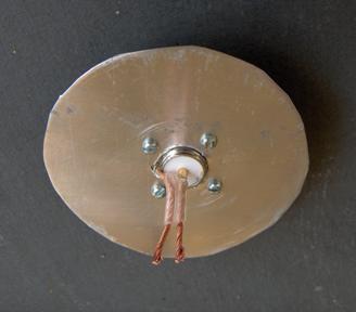
23 16-16 circular dipole antenna 6 VHF & UHF 144 MHz 122 cm 10 cm matching 15 pf 5 40 Variable Capacitor 15 PF Copper pipe 10 mm 122 mm 5 mm Matching 40 mm PL 219 or N type
24 VHF & UHF Folded dipole 7 4:1 6:1 balun : coaxial cable 4: RG
25 Loop Skye wire antenna - 8 /4 DX Omni direction MFJ 28 MHz 7MHz 300 Balun RG59 10m 21 MHz 14MHz 10m 5m HF Antenna tuner 6:1 4: mm Insulator /4 /4 /4 /4 300 cable /4 Must
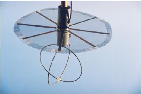
26 Egg Beater antenna - 9 pattern Vertical Vertical %10 VHF ground plane 4% + UHF F5VIF ON6WG : Nawa 1376 MHz 300 / 1376 = 218 cm + 8 = 226cm 10 mm 72 cm = 545 cm = 1/4 = ground plane 2725 cm = 1/8 = 90 = ¼ x 066 = 36 cm Velocity factor 066 RG cm 40 mm PVC RG58 1/8 100 rink /4 144
27
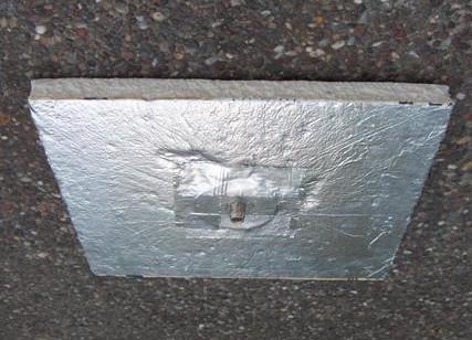
28 Liquid metal antenna -10 LM Antenna Mike Lake KD8CIK SWR Galinstan Galnnistan L Ground plane Compress air Coaxial cable Liquid metal antenna
29 Directional antenna HF Trap Trap Yagi boom radiation element :1 6:1 50 Balun 50 Folded Dipole boom HF 147
30 1 145 MHz 15 SWR DL6WU & VK5DJ 64 deg = 3 db 30 mm 444 mm 444 mm 155 mm 372 mm mm mm 145 MHz 10dBi = 2088 cm = beam width 25 mm = 10 mm = 1446 mm = 1015 mm = 974 mm = 993 mm = 915 mm = mm 906 mm = mm 897 mm = mm 30 mm = 148
31 : 2019 mm = 1009 mm = 25 mm = 50 mm = 459 mm = GF = HI 498 mm = GE = HA 538 mm = HB = GD 1009 mm = HC = GC 50mm 1015mm 993mm 915mm 906mm 897mm 30mm reflector 444mm 155mm 372mm 1446 mm radiator 445mm directors 5 Element 10dB! Folded Dipool Yagi 30mm
32 Cubical quad antenna - 2 2m VHF & UHF gamma tuner SWR 70 cm
33 Log periodic antenna HF & VHF & UHF broad band insulator Coaxial cable Log periodic antenna log periodic

34 VHF & UHF & Micro wave Helical antenna - 4 Anti Clock wise polarization Clock wise polarization PVC 40mm 150mm 40mm : 18dBi 42mm 07mm PVC 24GHz 550mm 130mm 12 1mm U ARRL / Helical

35 VHF& UHF microwave A horn antenna dBi 10GHz
36 Dish antenna - 6 Parabolic : LNB LNB LNB LNB Offset antenna LNB = F = D = d FOCUS D d F = D² 16 d X Y
37 Sect oral antenna x 62mm 2 mm 10mm RG mm RG Mobil GHz PCB PVC N type Balun 4:1 62 mm

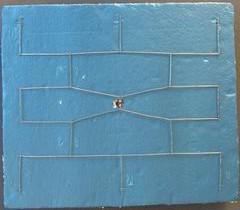
38 Moxon antenna 8 Les 360 Forward to back 11 HF Moxon G6XN ratio emition SWR : 55dBi KD6WD : 145 MHz : PVC 156
39 55 dbi 145 MHz VHF

40 Curtain Quad antenna - 9 foil 17dBi Ross Anderson W1HBQ 1 17dBi 24GHz
41
42 VHF & UHF 1/4 5/8 1/
CHAPTER 8 ANTENNAS 1
 CHAPTER 8 ANTENNAS 1 2 Antennas A good antenna works A bad antenna is a waste of time & money Antenna systems can be very inexpensive and simple They can also be very expensive 3 Antenna Considerations
Chapter 6 Antenna Basics. Dipoles, Ground-planes, and Wires Directional Antennas Feed Lines
 Chapter 6 Antenna Basics Dipoles, Ground-planes, and Wires Directional Antennas Feed Lines Some General Rules Bigger is better. (Most of the time) Higher is better. (Most of the time) Lower SWR is better.
Antennas and Propagation Chapters T4, G7, G8 Antenna Fundamentals, More Antenna Types, Feed lines and Measurements, Propagation
 Antennas and Propagation Chapters T4, G7, G8 Antenna Fundamentals, More Antenna Types, Feed lines and Measurements, Propagation =============================================================== Antenna Fundamentals
Amateur Radio License. Propagation and Antennas
 Amateur Radio License Propagation and Antennas Todays Topics Propagation Antennas Propagation Modes Ground wave Low HF and below, ground acts as waveguide Line-of-Sight (LOS) VHF and above, radio waves
4/29/2012. General Class Element 3 Course Presentation. Ant Antennas as. Subelement G9. 4 Exam Questions, 4 Groups
 General Class Element 3 Course Presentation ti ELEMENT 3 SUB ELEMENTS General Licensing Class Subelement G9 Antennas and Feedlines 4 Exam Questions, 4 Groups G1 Commission s Rules G2 Operating Procedures
Half-Wave Dipole. Radiation Resistance. Antenna Efficiency
 Antennas Simple Antennas Isotropic radiator is the simplest antenna mathematically Radiates all the power supplied to it, equally in all directions Theoretical only, can t be built Useful as a reference:
Antennas Demystified Antennas in Emergency Communications. Scott Honaker N7SS
 Antennas Demystified Antennas in Emergency Communications Scott Honaker N7SS Importance of Antennas Antennas are more important than the radio A $5000 TV with rabbit ears will have a lousy picture Antennas
Improved Ionospheric Propagation With Polarization Diversity, Using A Dual Feedpoint Cubical Quad Loop
 Improved Ionospheric Propagation With Polarization Diversity, Using A Dual Feedpoint Cubical Quad Loop by George Pritchard - AB2KC ab2kc@optonline.net Introduction This Quad antenna project covers a practical
Range Considerations for RF Networks
 TI Technology Days 2010 Range Considerations for RF Networks Richard Wallace Abstract The antenna can be one of the most daunting components of wireless designs. Most information available relates to large
FCC Technician License Course
 FCC Technician License Course 2014-2018 FCC Element 2 Technician Class Question Pool Presented by: Tamiami Amateur Radio Club (TARC) WELCOME To the third of 4, 3-hour classes presented by TARC to prepare
Antenna Trainer EAN. Technical Teaching Equipment INTRODUCTION
 Antenna Trainer EAN Technical Teaching Equipment Products Products range Units 3.-Communications INTRODUCTION Antennas are the main element of aerial communications. They are the transition between a transmission
Milton Keynes Amateur Radio Society (MKARS)
") Milton Keynes Amateur Radio Society (MKARS) Intermediate Licence Course Feeders Antennas Matching (Worksheets 31, 32 & 33) MKARS Intermediate Licence Course - Worksheet 31 32 33 Antennas Feeders Matching
Milton Keynes Amateur Radio Society (MKARS) Intermediate Licence Course Feeders Antennas Matching (Worksheets 31, 32 & 33) MKARS Intermediate Licence Course - Worksheet 31 32 33 Antennas Feeders Matching
4 Antennas as an essential part of any radio station
 4 Antennas as an essential part of any radio station 4.1 Choosing an antenna Communicators quickly learn two antenna truths: Any antenna is better than no antenna. Time, effort and money invested in the
Technician Licensing Class. Antennas
 Technician Licensing Class Antennas Antennas A simple dipole mounted so the conductor is parallel to the Earth's surface is a horizontally polarized antenna. T9A3 Polarization is referenced to the Earth
Fundamentals of Antennas. Prof. Ely Levine
 Fundamentals of Antennas Prof. Ely Levine levineel@zahav.net.il 1 Chapter 3 Wire Antennas 2 Types of Antennas 3 Isotropic Antenna Isotropic radiator is the simplest antenna mathematically Radiates all
Technician Licensing Class T9
 Technician Licensing Class T9 Amateur Radio Course Monroe EMS Building Monroe, Utah January 11/18, 2014 January 22, 2014 Testing Session Valid dates: July 1, 2010 June 30, 2014 Amateur Radio Technician
Least understood topics by most HAMs RF Safety Ground Antennas Matching & Feed Lines
 Least understood topics by most HAMs RF Safety Ground Antennas Matching & Feed Lines Remember this question from the General License Exam? G0A03 (D) How can you determine that your station complies with
Chapter 5.0 Antennas Section 5.1 Theory & Principles
 Chapter 5.0 Antennas Section 5.1 Theory & Principles G3C11 (B) p.135 Which of the following antenna types will be most effective for skip communications on 40-meters during the day? A. A vertical antenna
4/25/2012. Supplement T9. 2 Exam Questions, 2 Groups. Amateur Radio Technician Class T9A: T9A: T9A: T9A:
 Amateur Radio Technician Class Element 2 Course Presentation ti ELEMENT 2 SUB-ELEMENTS Technician Licensing Class Supplement T9 Antennas, Feedlines 2 Exam Questions, 2 Groups T1 - FCC Rules, descriptions
# -antenna (hash) 4 direction switchable array
 4 direction switchable array") # -antenna (hash) 4 direction switchable array Feasibility study Paper on CCF & OHDXF cruise 4.1.2012 Pekka Ketonen 4.2.2012 OH1TV 1 4 direction, instant switching 4.2.2012 OH1TV 2 Features Instant direction
# -antenna (hash) 4 direction switchable array Feasibility study Paper on CCF & OHDXF cruise 4.1.2012 Pekka Ketonen 4.2.2012 OH1TV 1 4 direction, instant switching 4.2.2012 OH1TV 2 Features Instant direction
Network Analyzer and Spectrum Analyzer Measurements of Antennas and RF Components
 Network Analyzer and Spectrum Analyzer Measurements of Antennas and RF Components قياسات أنظمة أإلتصاالت ألعامله بألترددات ألراديويه وألميكرويفيه وتحليل وفحص ألهوائيات محمد ألنظامي by: Dr. Mohamed K. Nezami
Colubris Networks. Antenna Guide
 Colubris Networks Antenna Guide Creation Date: February 10, 2006 Revision: 1.0 Table of Contents 1. INTRODUCTION... 3 2. ANTENNA TYPES... 3 2.1. OMNI-DIRECTIONAL ANTENNA... 3 2.2. DIRECTIONAL ANTENNA...
Dr. John S. Seybold. November 9, IEEE Melbourne COM/SP AP/MTT Chapters
 Antennas Dr. John S. Seybold November 9, 004 IEEE Melbourne COM/SP AP/MTT Chapters Introduction The antenna is the air interface of a communication system An antenna is an electrical conductor or system
Technician License. Course
 Technician License Course Technician License Course Chapter 4 Lesson Plan Module - 10 Practical Antennas The Dipole Most basic antenna The Dipole Most basic antenna The Dipole Total length is ½ wavelength
ANTENNAS. I will mostly be talking about transmission. Keep in mind though, whatever is said about transmission is true of reception.
 Reading 37 Ron Bertrand VK2DQ http://www.radioelectronicschool.com ANTENNAS The purpose of an antenna is to receive and/or transmit electromagnetic radiation. When the antenna is not connected directly
August, Antennas 101: A Course in RF Basics
 August, 2012 Antennas 101: A Course in RF Basics Antenna Basics Agenda: In today s training, we will go over a brief summary of the following topics at a basic level: Electromagnetic Waves Frequency and
Technician License Course Chapter 4. Lesson Plan Module 9 Antenna Fundamentals, Feed Lines & SWR
 Technician License Course Chapter 4 Lesson Plan Module 9 Antenna Fundamentals, Feed Lines & SWR The Antenna System Antenna: Transforms current into radio waves (transmit) and vice versa (receive). Feed
Portable Vertical Antenna for 75m & 40m
 Portable Vertical Antenna for 75m & 40m BOXBORO August 2012 Jacques VE2AZX Web: ve2azx.net 1 Objectives 1- Portable Antenna for 75m et 40m 2- Low radiation angle for DX 3- Efficient 4- Easy to install.
BHARATHIDASAN ENGINEERING COLLEGE NATTARAMPALLI Frequently Asked Questions (FAQ) Unit 1
 Unit 1") BHARATHIDASAN ENGINEERING COLLEGE NATTARAMPALLI 635854 Frequently Asked Questions (FAQ) Unit 1 Degree / Branch : B.E / ECE Sem / Year : 3 rd / 6 th Sub Name : Antennas & Wave Propagation Sub Code : EC6602
BHARATHIDASAN ENGINEERING COLLEGE NATTARAMPALLI 635854 Frequently Asked Questions (FAQ) Unit 1 Degree / Branch : B.E / ECE Sem / Year : 3 rd / 6 th Sub Name : Antennas & Wave Propagation Sub Code : EC6602
The Reverse Polarity TNC(m) RF connector can be easily secured or removed from equipment in the field by a single gloved hand, no tools required.
 RF connector can be easily secured or removed from equipment in the field by a single gloved hand, no tools required.") Overview Southwest Antennas is a half wave dipole omni antenna with a frequency range of 1.35 to 1.40 GHz and 2.15 dbi of peak gain. This product features an integrated RF bandpass filter to help eliminate
Overview Southwest Antennas is a half wave dipole omni antenna with a frequency range of 1.35 to 1.40 GHz and 2.15 dbi of peak gain. This product features an integrated RF bandpass filter to help eliminate
Back to the Basics Setting up a VHF/UHF Station
 Back to the Basics Setting up a VHF/UHF Station Back to The Basics Your First VHF/UHF Station Topics that will be covered: Radios l Base/mobile vs. Hand Held l Pluses and minuses of each l Antennas l Vertical
Cray Valley Radio Society. Real Life Wire Antennas
 Cray Valley Radio Society Real Life Wire Antennas 1 The basic dipole The size of an antenna is determined by the wavelength of operation In free space: ~3x10 8 m/s Frequency x Wavelength = Speed of Light,
Multimedia Training Kit
 Multimedia Training Kit Antennas and Cables Alberto Escudero Pascual, IT+46 Goals Focus on explaining the losses in the link budget equation Introduce a set of types of antennas and cables How to make
Users Manual. 200W HF/50MHz Band Auto Antenna Tuner. Model HC-200AT
 Users Manual 200W HF/50MHz Band Auto Antenna Tuner Model HC-200AT Caution 1. Never remove or open the tuner cover while transmitting. When there is RF in the circuits of the tuner, there will be high voltage
This Antenna Basics reference guide includes basic information about antenna types, how antennas work, gain, and some installation examples.
 Antenna Basics This Antenna Basics reference guide includes basic information about antenna types, how antennas work, gain, and some installation examples. What Do Antennas Do? Antennas transmit radio
Technician License Course Chapter 4. Lesson Plan Module 10 Practical Antennas
 Technician License Course Chapter 4 Lesson Plan Module 10 Practical Antennas The Dipole Most basic antenna Total length is ½ wavelength (½ λ) Usual construction: Two equal halves of wire, rod, or tubing
ANTENNAS Wires, Verticals and Arrays
 ANTENNAS Wires, Verticals and Arrays Presented by Pete Rimmel N8PR 2 1 Tonight we are going to talk about antennas. Anything that will conduct electricity can be made to radiate RF can be called an antenna.
Technician License. Course
 Technician License Course Technician License Course Chapter 4 Lesson Plan Module - 9 Antenna Fundamentals Feed Lines & SWR The Antenna System The Antenna System Antenna: Transforms current into radio waves
KULLIYYAH OF ENGINEERING
 KULLIYYAH OF ENGINEERING DEPARTMENT OF ELECTRICAL & COMPUTER ENGINEERING ANTENNA AND WAVE PROPAGATION LABORATORY (ECE 4103) EXPERIMENT NO 3 RADIATION PATTERN AND GAIN CHARACTERISTICS OF THE DISH (PARABOLIC)
ANTENNAS FEED POINTS. An antenna is a mechanical structure by which electromagnetic waves are sent out or received.
 ANTENNAS An antenna is a mechanical structure by which electromagnetic waves are sent out or received. An antenna accomplishes this by being made so that its structure will be resonant at the frequency
Antennas & Transmission Lines
 Antennas & Transmission Lines Network Startup Resource Center www.nsrc.org These materials are licensed under the Creative Commons Attribution-NonCommercial 4.0 International license (http://creativecommons.org/licenses/by-nc/4.0/)
Antenna Basics. Antennas. A guide to effective antenna use
 A guide to effective antenna use Antennas Antennas transmit radio signals by converting radio frequency electrical currents into electromagnetic waves. Antennas receive the signals by converting the electromagnetic
Development of a noval Switched Beam Antenna for Communications
 Master Thesis Presentation Development of a noval Switched Beam Antenna for Communications By Ashraf Abuelhaija Supervised by Prof. Dr.-Ing. Klaus Solbach Institute of Microwave and RF Technology Department
CHAPTER 5 THEORY AND TYPES OF ANTENNAS. 5.1 Introduction
 CHAPTER 5 THEORY AND TYPES OF ANTENNAS 5.1 Introduction Antenna is an integral part of wireless communication systems, considered as an interface between transmission line and free space [16]. Antenna
UNIVERSITI MALAYSIA PERLIS
 UNIVERSITI MALAYSIA PERLIS SCHOOL OF COMPUTER & COMMUNICATIONS ENGINEERING EKT 341 LABORATORY MODULE LAB 2 Antenna Characteristic 1 Measurement of Radiation Pattern, Gain, VSWR, input impedance and reflection
Resonant Antennas: Wires and Patches
 Resonant Antennas: Wires and Patches Dipole Antennas Antenna 48 Current distribution approximation Un-normalized pattern: and Antenna 49 Radiating power: For half-wave dipole and,, or at exact resonance.
ANTENNAS 101 An Introduction to Antennas for Ham Radio. Lee KD4RE
 ANTENNAS 101 An Introduction to Antennas for Ham Radio Lee KD4RE Prepared for Presentation at the Vienna Wireless Society, 13 January 2017 So What is an Antenna Anyway? We are all familiar with wire antennas
Broadband Antenna. Broadband Antenna. Chapter 4
 1 Chapter 4 Learning Outcome At the end of this chapter student should able to: To design and evaluate various antenna to meet application requirements for Loops antenna Helix antenna Yagi Uda antenna
Practical Antennas and. Tuesday, March 4, 14
 Practical Antennas and Transmission Lines Goals Antennas are the interface between guided waves (from a cable) and unguided waves (in space). To understand the various properties of antennas, so as to
VHF/UHF Dual Band J-Pole. By: Ed Fong WB6IQN
 VHF/UHF Dual Band J-Pole By: Ed Fong WB6IQN email: edison_fong@hotmail.com ARRL VHF/UHF Antenna Classics ARRL Vol. 8 Antenna Compendium ARRL Vol. 3 Antenna Compendium QST March 2007 QST February 2003 QST
Antenna Glossary. BEAMWIDTH The angle of signal coverage provided by an antenna. Beamwidth usually decreases as antenna gain increases.
 ADAPTIVE (SMART) ANTENNA An antenna system having circuit elements associated with its radiating elements such that one or more of the antenna properties are controlled by the received signal. ANTENNA
02680SX Series UHF Mount Dipole Array Series
 02680SX Series UHF Mount Dipole Array Series Page 1 of 11 Description The 02680SX series antennas are 0dB, 3dB and 6dB Gain, Stainless Steel Side Mount Dipole Array antennas, for use in the Commercial
Technician Licensing Class. Lesson 4. presented by the Arlington Radio Public Service Club Arlington County, Virginia
 Technician Licensing Class Lesson 4 presented by the Arlington Radio Public Service Club Arlington County, Virginia 1 Quiz Sub elements T6 & T7 2 Good Engineering Practice Sub element T8 3 A Basic Station
KINGS COLLEGE OF ENGINEERING. DEPARTMENT OF ELECTRONICS AND COMMUNICATION ENGINEERING Academic Year (Even Sem) QUESTION BANK (AUTT-R2008)
 QUESTION BANK (AUTT-R2008)") KINGS COLLEGE OF ENGINEERING DEPARTMENT OF ELECTRONICS AND COMMUNICATION ENGINEERING Academic Year 2012-2013(Even Sem) QUESTION BANK (AUTT-R2008) SUBJECT CODE /NAME: EC 1352 / ANTENNEA AND WAVE PROPAGATION
KINGS COLLEGE OF ENGINEERING DEPARTMENT OF ELECTRONICS AND COMMUNICATION ENGINEERING Academic Year 2012-2013(Even Sem) QUESTION BANK (AUTT-R2008) SUBJECT CODE /NAME: EC 1352 / ANTENNEA AND WAVE PROPAGATION
High Speed Data Downlink for NSF Space Weather CubeSats
 High Speed Data Downlink for NSF Space Weather CubeSats National Science Foundation Meeting Monday August 31, 2009 Charles Swenson Satellite Data Flow Onboard Instruments R collected Spacecraft Memory
50MHz Collapsible 2 Element Mini Beam: An Overview the Development of the 6MBA
 50MHz Collapsible 2 Element Mini Beam: An Overview the Development of the 6MBA Presented by: Mike Parkin GØJMI (Design featured in RSGB s September 2012 Rad Com ) Slide 1 Introduction Mike Parkin: First
Last year I described several Low Band RX antennas that would enable you to hear DX stations on 160, 80 and 40M. This will show you how to build
 Last year I described several Low Band RX antennas that would enable you to hear DX stations on 160, 80 and 40M. This will show you how to build transmit antennas that will help you break the pileups!
Yagi beam antennas CHAPTER 10 COMPOSITION OF A BEAM ANTENNA _
 CHAPTER 10 Yagi beam antennas The Yagi beam antenna (more correctly, the Yagi Uda antenna, after both of the designers of Tohoku University in Japan 1926) is unidirectional. It can be vertically polarized
Antenna Fundamentals. Microwave Engineering EE 172. Dr. Ray Kwok
 Antenna Fundamentals Microwave Engineering EE 172 Dr. Ray Kwok Reference Antenna Theory and Design Warran Stutzman, Gary Thiele, Wiley & Sons (1981) Microstrip Antennas Bahl & Bhartia, Artech House (1980)
Antennas 101 Don t Be a 0.97 db Weakling! Ward Silver NØAX
 Antennas 101 Don t Be a 0.97 db Weakling! Ward Silver NØAX Overview Antennas 101 2 Overview Basic Antennas: Ground Plane / Dipole How Gain and Nulls are Formed How Phased Arrays Work How Yagis Work (simplified)
Basic Wire Antennas. Part II: Loops and Verticals
 Basic Wire Antennas Part II: Loops and Verticals A loop antenna is composed of a single loop of wire, greater than a half wavelength long. The loop does not have to be any particular shape. RF power can
Intermediate Course (5) Antennas and Feeders
 Antennas and Feeders") Intermediate Course (5) Antennas and Feeders 1 System Transmitter 50 Ohms Output Standing Wave Ratio Meter Antenna Matching Unit Feeder Antenna Receiver 2 Feeders Feeder types: Coaxial, Twin Conductors
Intermediate Course (5) Antennas and Feeders 1 System Transmitter 50 Ohms Output Standing Wave Ratio Meter Antenna Matching Unit Feeder Antenna Receiver 2 Feeders Feeder types: Coaxial, Twin Conductors
KINGS COLLEGE OF ENGINEERING DEPARTMENT OF ELECTRONICS AND COMMUNICATION ENGINEERING QUESTION BANK
 KINGS COLLEGE OF ENGINEERING DEPARTMENT OF ELECTRONICS AND COMMUNICATION ENGINEERING QUESTION BANK SUB.NAME : ANTENNAS & WAVE PROPAGATION SUB CODE : EC 1352 YEAR : III SEMESTER : VI UNIT I: ANTENNA FUNDAMENTALS
Chapter 9 Antennas and Feedlines
 Chapter 9 Antennas and Feedlines Basics of Antennas Antenna Radiation Patterns. Graphical representation of spatial distribution of energy around an antenna. 3D = Full representation. 2D = Slice through
General License Class Chapter 6 - Antennas. Bob KA9BHD Eric K9VIC
 General License Class Chapter 6 - Antennas Bob KA9BHD Eric K9VIC Learning Objectives Teach you enough to get all the antenna questions right during the VE Session Learn a few things from you about antennas
Optimizing Your Stations Performance
 Optimizing Your Stations Performance A few hints / techniques, recommendations for getting the most RF out to the Antenna from your HF, VHF / UHF station. Tonights Presenters: Doug Theriault NO1D John
Sebastian Büttrich, wire.less.dk edit: September 2009, Pokhara, Nepal. Shortened version of
 Antennas and Cables Sebastian Büttrich, wire.less.dk edit: September 2009, Pokhara, Nepal Shortened version of http://www.itrainonline.org/itrainonline/mmtk/wireless_en/08_antennas_cables/08_en_mmtk_wireless_antennas-cables_slides.odp
A short, off-center fed dipole for 40 m and 20 m by Daniel Marks, KW4TI
 A short, off-center fed dipole for 40 m and 20 m by Daniel Marks, KW4TI Version 2017-Nov-7 Abstract: This antenna is a 20 to 25 foot long (6.0 m to 7.6 m) off-center fed dipole antenna for the 20 m and
Table of Contents. MFJ-1778 G5RV Multiband Antenna
 Table of Contents MFJ-1778 G5RV Multiband Antenna Introduction... 1 Theory Of Operation... 1 80 meter band:... 1 40 meter band:... 1 30 meter band:... 2 20 meter band:... 2 17 meter band:... 2 15 meter
FM BROADCASTING BAND II 4 WAY dbi STACKED CIRCULAR ANTENNA
 FM BROADCASTING BAND II 4 WAY + 5.8 dbi STACKED CIRCULAR ANTENNA Please read this manual carefully. To avoid harmful interference to other users of the electromagnetic spectrum, do not power up the antenna
MFJ-219/219N 440 MHz UHF SWR Analyzer TABLE OF CONTENTS
 MFJ-219/219N 440 MHz UHF SWR Analyzer TABLE OF CONTENTS Introduction...2 Powering The MFJ-219/219N...3 Battery Installation...3 Operation Of The MFJ-219/219N...4 SWR and the MFJ-219/219N...4 Measuring
Traveling Wave Antennas
 Traveling Wave Antennas Antennas with open-ended wires where the current must go to zero (dipoles, monopoles, etc.) can be characterized as standing wave antennas or resonant antennas. The current on these
Contents. ITS323: Introduction to Data Communications CSS331: Fundamentals of Data Communications. Transmission Media and Spectrum.
 2 ITS323: Introduction to Data Communications CSS331: Fundamentals of Data Communications Sirindhorn International Institute of Technology Thammasat University Prepared by Steven Gordon on 3 August 2015
ITS323: Introduction to Data Communications CSS331: Fundamentals of Data Communications
 ITS323: Introduction to Data Communications CSS331: Fundamentals of Data Communications Sirindhorn International Institute of Technology Thammasat University Prepared by Steven Gordon on 3 August 2015
6 Radio and RF. 6.1 Introduction. Wavelength (m) Frequency (Hz) Unit 6: RF and Antennas 1. Radio waves. X-rays. Microwaves. Light
 Frequency (Hz) Unit 6: RF and Antennas 1. Radio waves. X-rays. Microwaves. Light") 6 Radio and RF Ref: http://www.asecuritysite.com/wireless/wireless06 6.1 Introduction The electromagnetic (EM) spectrum contains a wide range of electromagnetic waves, from radio waves up to X-rays (as
6 Radio and RF Ref: http://www.asecuritysite.com/wireless/wireless06 6.1 Introduction The electromagnetic (EM) spectrum contains a wide range of electromagnetic waves, from radio waves up to X-rays (as
RVRUSA - DATA DE REFERENCIA PARA INGENIEROS
 Useful formulae Electrical formulae Electrical power in KW: DC power [KW]: YROW DPSHUH YROW DPSHUH AC power (single phase) [KW]: AC power (three-phase) [KW]: where: cos( j ) YROW DPSHUH 73. cos( j) Volt:
The Amazing MFJ 269 Author Jack Tiley AD7FO
 The Amazing MFJ 269 Author Jack Tiley AD7FO ARRL Certified Emcomm and license class Instructor, Volunteer Examiner, EWA Technical Coordinator and President of the Inland Empire VHF Club What Can be Measured?
SI TECHNICAL 2018 UNIT IV QUESTION BANK
 SI TECHNICAL 2018 UNIT IV QUESTION BANK 1. In what range of frequencies are most omnidirectional horizontally polarized antennas used? A. VHF, UHF B. VLF, LF C. SH, EHF D. MF, HF 2. If the current ratios
1 Propagation in free space and the aperture antenna
 1 Propagation in free space and the aperture antenna This chapter introduces the basic concepts of radio signals travelling from one antenna to another. The aperture antenna is used initially to illustrate
ANTENNA BASICS FOR BEGINNERS
 ANTENNA BASICS FOR BEGINNERS PART 2 -DIPOLES DIPOLES -General MULTIBAND DIPOLES RF CHOKES 1 DIPOLES Several different variations of the dipole are also used, such as the folded dipole, short dipole, cage
FIELD INTENSITY AND SIGNAL LEVEL
 FIELD INTENSITY AND SIGNAL LEVEL It is important to understand the relationship between field intensity and the signal level at the input to a receiver or other monitoring device. For example, pager sensitivity
EEM.Ant. Antennas and Propagation
 EEM.ant/0304/08pg/Req: None 1/8 UNIVERSITY OF SURREY Department of Electronic Engineering MSc EXAMINATION EEM.Ant Antennas and Propagation Duration: 2 Hours Spring 2003/04 READ THESE INSTRUCTIONS Answer
Advanced Test Equipment Rentals ATEC (2832)
") Established 1981 Advanced Test Equipment Rentals www.atecorp.com 800-404-ATEC (2832) LOG PERIODIC DIPOLES 20 MHz - 18 GHz TRANSMIT - RECEIVE SPECIFICATIONS ELECTRICAL Impedance: 50 ohms INDIVIDUALLY CALIBRATED
Established 1981 Advanced Test Equipment Rentals www.atecorp.com 800-404-ATEC (2832) LOG PERIODIC DIPOLES 20 MHz - 18 GHz TRANSMIT - RECEIVE SPECIFICATIONS ELECTRICAL Impedance: 50 ohms INDIVIDUALLY CALIBRATED
MICROWAVE MICROWAVE TRAINING BENCH COMPONENT SPECIFICATIONS:
 Microwave section consists of Basic Microwave Training Bench, Advance Microwave Training Bench and Microwave Communication Training System. Microwave Training System is used to study all the concepts of
SD230T. Frequency Range, MHz Average, 0.6 PEP,1 Average, 3 PEP. <2.0:1 for 3 to 20MHz, <2.5:1 for 2 to 30MHz
 Tactical Semidelta Antennas 2-30MHz SD-T Series The RFS Model SD230T antenna is a transportable, broadband, lightweight, traveling wave antenna for short to medium range ionospheric communications. For
FAST MAST ANTENNA SYSTEM
 FAST MAST ANTENNA SYSTEM FAST DEPLOYMENT RECEIVER HITCH 25 ANTENNA TOWER DEPLOY YOUR ANTENNA SYSTEM IN LESS THAN 5 MINUTES THE EXTENDS FROM 7.5 FT UP TO 25 FT OR ANY POINT INBETWEEN. CONSTRUCTED FROM HEAVY
TZ-RD-1740 Rotary Dipole Instruction Manual
 TZ-RD-1740 17/40m Rotary Dipole Instruction Manual The TZ-RD-1740 is a loaded dipole antenna for the 40m band and a full size rotary dipole for the 17m band. The antenna uses an aluminium radiating section
Antenna Design for FM-02
 Antenna Design for FM-02 I recently received my FM-02 FM transmitter which I purchased from WLC. I researched the forum on what antennas where being used by the DIY community and found a nice write-up
July 1995 QST Volume 79, Number 7
 Lab Notes Prepared by the ARRL Laboratory Staff (e-mail: tis@arrl.org) By Mike Tracy, KC1SX Technical Information Service Coordinator Q: I m just getting started on VHF and UHF FM and I want to set up
INSTRUCTION MANUAL. Specifications Mechanical. 1 5/8 to 2 1/16 O.D. (41mm to 52mm)
") 308 Industrial Park Road Starkville, MS 39759 USA Ph: (662) 323-9538 FAX: (662) 323- General Description Model VB-25FM 2-Meter 5 Elements Beam INSTRUCTION MANUAL This antenna is a 5-element, 2-meter beam
308 Industrial Park Road Starkville, MS 39759 USA Ph: (662) 323-9538 FAX: (662) 323- General Description Model VB-25FM 2-Meter 5 Elements Beam INSTRUCTION MANUAL This antenna is a 5-element, 2-meter beam
Antennas. You re heard, loud and clear.
 Antennas You re heard, loud and clear. PIM-RATED ANTENNAS COL Series VHF and UHF Meander Collinear The Meander Collinear Antennas, available in both the VHF, UHF and 700/800 MHz bands, have been specifically
S.R.M. Institute of Science & Technology Deemed University School of Electronics & Communication Engineering
 S.R.M. Institute of Science & Technology Deemed University School of Electronics & Communication Engineering Question Bank Subject Code : EC401 Subject Name : Antennas and Wave Propagation Year & Sem :
Chapter 6 Broadband Antenna. 1. Loops antenna 2. Heliksantenna 3. Yagi uda antenna
 Chapter 6 Broadband Antenna 1. Loops antenna 2. Heliksantenna 3. Yagi uda antenna 1 Design A broadband antenna should have acceptable performance (determined by its pattern, gain and/or feed-point impedance)
INSTITUTE OF AERONAUTICAL ENGINEERING Dundigal, Hyderabad ELECTRONICS AND COMMUNIACTION ENGINEERING QUESTION BANK
 INSTITUTE OF AERONAUTICAL ENGINEERING Dundigal, Hyderabad - 500 04 ELECTRONICS AND COMMUNIACTION ENGINEERING QUESTION BANK Course Name : Antennas and Wave Propagation (AWP) Course Code : A50418 Class :
Antennas & wave Propagation ASSIGNMENT-I
 Shri Vishnu Engineering College for Women :: Bhimavaram Department of Electronics & Communication Engineering Antennas & wave Propagation 1. Define the terms: i. Antenna Aperture ii. Beam Width iii. Aperture
The quality you expect at the price you want to pay. Available at: 1 (888) (866)
 (866)") The quality you expect at the price you want to pay Available at: www.wirelessource.ca 1 (888) 430-0660 1 (866) 244-4844 October 2014 VHF Mobile Antennas... P1-5 UHF Mobile Antennas... P6-9 CB Mobile Antennas...
The quality you expect at the price you want to pay Available at: www.wirelessource.ca 1 (888) 430-0660 1 (866) 244-4844 October 2014 VHF Mobile Antennas... P1-5 UHF Mobile Antennas... P6-9 CB Mobile Antennas...
The db Concept. Chapter six
 Chapter six The db Concept CHAPTER OUTLINE dbdpower Ratio... 40 dbdamplitude Ratio... 40 From db to Power or Amplitude Ratio... 41 Conversion Table... 41 Reference Values... 41 Other Relative Units...43
ANTENNA THEORY WAVE PROPAGATION HF ANTENNAS
 ANTENNA THEORY WAVE PROPAGATION & HF ANTENNAS FREQUENCY SPECTRUM INFORMATION Frequency range American designator below 300 Hz..ELF (extremely Low Frequency) 300-3000 Hz..ILF (Intermediate Low Frequency)
Antennas Prof. Girish Kumar Department of Electrical Engineering India Institute of Technology, Bombay. Module - 1 Lecture - 1 Antennas Introduction-I
 Antennas Prof. Girish Kumar Department of Electrical Engineering India Institute of Technology, Bombay Module - 1 Lecture - 1 Antennas Introduction-I Hello everyone. Welcome to the exciting world of antennas.
The A-B-C's of Radio Waves and Antennas
 The A-B-C's of Radio Waves and Antennas By Greg S. Carpenter GregsBasicElectronics.com What is the most important thing in common with both the transmitter and receiver? It's the antenna and without a