Reducing Noise in Power Distribution Networks On time and In Budget
|
|
|
- Hester Summers
- 6 years ago
- Views:
Transcription
")
1 TITLE Reducing Noise in Power Distribution Networks On time and In Budget Steve Sandler, (Picotest) Image

2 Reducing Noise in Power Distribution Networks On time and In Budget Steve Sandler, (Picotest)

3 So, What is noise

4 And What is a PDN R R1 V_Noise SRC1 L L1 TLIN TL1 SRL SRLC SRLC1 TLIN TL1 SRL1TLIN TL1 SRL SRL1 C C1 SRL SRL1 R R1 C R C1 R1 I_Noise SRC2 I_Noise SRC2 Loads VRM

 Port 1 Iin")

5 Reverse (S12) A VRM is a Noise Hub Output Impedance (S22) PSRR (S21) Input impedance (S11) Port 1 Iin Vin In Out Rtn Port 2 Iout Vout Output noise/spikes (S22)

6 Know Your Loads What can they tolerate and what can t they tolerate 4E-08 3E-08 Clock Jitter Sensitivity 100uV 50kHz noise=23db degradation s/v 2E-08 1E E E E E+06 Frequency (Hz) Oscillators, sensors, ADCs and DACs are often sensitive to uvs of noise


7 Linear Regulators and LDO s are not the same, though either can have spurs! And Your VRMs 100uV 50kHz noise=23db degradation Switching regulators can modulate generating low frequency noise
8 Set and Maintain Goldilocks Impedance Not too low Not too high Just right CC = LL TR1 ZZ2 dddddddddddddd 6*10 0 2* * f/hz Setting impedance too high results in noise Too low results in resonances or excessive (expensive) capacitance Moving regulators closer to the load reduces L
 don t choose a regulator with high impedance at 30kHz! s/v Clock Jitter Sensitivity 3.5E-08 3E-08 2.5E-08 2E-08 1.5E-08 1E-08 5E-09 0 1.")
9 Spend Most of Your Time Evaluating NOT Designing If you selected a clock with high sensitivity at 30kHz (??) don t choose a regulator with high impedance at 30kHz! s/v Clock Jitter Sensitivity 3.5E-08 3E E-08 2E E-08 1E-08 5E E E E E+06 Frequency (Hz)


10 Choose Components Wisely Ceramic is almost always a poor choice so include series resistance options 10mΩ New components are like a box of cracker Jacks SURPRISE INSIDE

11 Consider the Unexpected OOPS happens! Suffers from high Z power At 30kHz Then POWER-SAVER came on


12 Think RF/uWave PCB Simulation is Important Capacitors and PCB s can easily form a resonator Q=4 12dB C603=10nF C603=0nF 20MHz resonance Cause by 10nF cap


13 Troubleshoot Efficiently Two domains are better than one and three are better than 2 Plane Impedance Near Field emissions over plane This 29MHz noise (and EMI) are the result of two capacitors resonating a PCB plane


14 Interrogate your PDN Even if It Looks OK Nobody likes surprises (especially when they occur in the field) A wideband harmonic comb and browser probe can quickly identify PDN soft spots between 1kHz and more than 1GHz
15 Summary 1.Set impedance wisely and keep it flat 2.Spend more time evaluating and less time designing 3.Prepare for the unexpected 4.Troubleshoot efficiently 5.Interrogate to identify weak or sensitive spots Thank You!


16 Thanks for Attending! Steve Sandler has been involved with power system engineering for more than 37 years. Steve is the founder of of PICOTEST.com, a company specializing in accessories for high performance power system and distributed system testing. He frequently lectures and leads workshops internationally on the topics of power, PDN and distributed systems. He is also the other of Power Integrity from McGraw-Hill He was also the recipient of the ACE 2015 Jim Williams Contributor of the Year ACE Award for his outstanding and continuing contributions to the engineering industry and knowledge sharing. Contact me through our LinkedIn group Power Integrity for Distributed Systems or me at Steve@Picotest.com
17 TITLE Reducing Noise in Power Distribution Networks On time and In Budget Tom De Muer Image Keysight Technologies


18 Power Delivery Network Design Board Impedance VRM Capacitors Resonances Board And Capacitor Resonances Courtesy of Xilinx
19 Reducing Noise in Power Distribution Networks On Time Reduce # of spins of board Early insight in design phase by simulation In Budget Reduce part count and part diversity 100uV (BOM) 50kHz noise=23db degradation EDA Tools help Complexity of boards is beyond back of the envelope calculations Effects interact on various scales and often require an EM-based solution Lower barrier for designers to perform PI analysis early in the design cycle

 PI capabilities increase designer s user experience and speak the language of the")
20 EDA Tools are Easier to Use EDA Tools bring a cohesive and performance based flow from board design to analysis and manufacturing to avoid Manual operations and translations between tools as a source of error Time consuming brute-force simulations EDA tools matured over the years 100uV 50kHz noise=23db degradation Bringing together design and various analysis capabilities to more timely and easily verify and predict performance Dedicated (SI and) PI capabilities increase designer s user experience and speak the language of the designer
21 Simulation Capacity has Increased Dramatically Ubiquitous availability of Large amounts of high-speed memory Multi-core processing power Cost of 1 GFlop in 2000 was > 500$, cost in 2015 < 0.08$ Cost of 1 GB in 2000 was > 1500$, cost in 2015 < 8$ Simulators (need to) keep up Prefer parallelization to take advantage of multi-core Can trade an increase memory for boost in performance Use domain expertise in more evolved simulators Exchange performance for accuracy dynamically where acceptable Automatically distribute work to sub-simulators with better characteristics while tracking relevant EM effects across elements of simulations But can we keep up with ever increasing design complexity?
22 TITLE Unachievable Goal: REDUCING NOISE IN POWER DISTRIBUTION NETWORKS ON TIME AND IN BUDGET Image Dan Oh Altera Corporation
23 Basics of PDN Design + _ PCB cap PKG cap On Chip Decap VRM PCB PDN Package PDN Chip PDN (log) Z PDN PCB Bulk Caps PCB SMC Pkg Cap Low-frequency (VRM, Bulkcaps) 10K 500KHz Mid-frequency (PCB,PKG caps) 10M 400MHz High-frequency (ODC, Jitter) (log)
 Changes during design cycle Noise Specs Noise spec is derived based on rough estimation or target")
24 PDN Budgeting and Planning Lpkg Power (Max, leakage) Activity Pattern Board PDN Components Vreg Tolerance On-Die Cap (MiMcap, Symbiotic caps) Changes during design cycle Noise Specs Noise spec is derived based on rough estimation or target values
25 PDN Design Challenges Process technology continue to shrink More transistors power increase On-chip decap does not scale as it is a purely proportional to area MIM cap technology improves slowly due to reliability concern Think dielectric layer or new dielectric material is needed to increase cap (C ~ A/d) No improvement in packaging technology from power delivery perspective Ball and bump counts very slowly increase PTH count also does not increase so much PCB decoupling technology remains same The available area to place decaps does not increase

 STA")

26 How Noise Spec is Used in Design Architecture Definition Noise is translated to voltage corners for IPs Package Inductance Change Decap Density Change Silicon Tapeout Product Release Static Timing Analysis (STA) timing models are generated at the voltage corners (Noise is mapped to DC timing delays in STA IP LIBs) STA performs analysis including DC timing delay caused by noise Power Change An inherent gap between the final noise versus initial spec due to inevitable design changes
27 Potential Solutions Extra noise can be modeled as an equivalent timing margin in the final STA timing closure Timing error due to noise can be significantly reduced if noise frequency is considered FPGA advantages Adequate timing margin can be enforced based on customer design Our DesignCon presentations: WED 9:30AM: impacts of dynamic noise in multi-core or SOC designs TH 2:00PM: chip, package, and pcb co-design methodology to address PDN design challenges for high-performance SOCs and FPGAs
 Longer Delay Low")
 -20dB/dec Conventional STA -3dB point (0.")
28 Benefits of STAJ Arrival Path Source Destination INBU F PLL Required Path Sensitivity reduction over the frequency modeled (LF) Longer Delay Low frequency reduced Jitter tracking between arrival and required paths (HF) anti-correlation (2 at 0.5*fck) -20dB/dec Conventional STA -3dB point (0.7 at ~0.1*fck)
 70ps if jitter frequency and tracking is modeled accurately 34mV")
29 Pessimism Removal Due to Jitter Modeling 267ps using static delay (0.2 tck) 70ps if jitter frequency and tracking is modeled accurately 34mV 108mV
30 TITLE REDUCING NOISE IN POWER DISTRIBUTION NETWORKS ON TIME AND IN BUDGET Image Vishram Pandit Intel Corporation
31 Introduction Noise in Power Distribution Network (PDN) has multiple effects (1) Higher Jitter Logic Failure EMI Coupling to signal lines Typical Noise influencing parameters PDN Network: On-chip capacitance/ package inductance; pkg capacitors; board capacitors/ inductance. Di/dt, Skews/ delays, Power Management Voltage regulators Optimization of PDN Bill of Material (BOM) cost
32 Signaling Impact PDN noise and its impact on system performance (2) Jitter Jitter Tolerance and System Margin PDN Noise coupling to signal lines: (1) (3) (4) Referencing Via placement/ stitching, connectivity Power/ground shapes Capacitors
33 PDN Coupling Effects Coupling criterion: Noise and jitter SoC Coupling effects need to be considered Coupling through silicon and pkg (9) Different types of coupling IP to IP coupling may deteriorate performance of sensitive circuits Various techniques to reduce the coupling Chip/ Pkg/ PCB level isolation Location of different components
34 Improving PDN Designs Power grid impact on the system Power Integrity (5) Symbiotic or intrinsic capacitance (6) Placement of on-chip capacitance Ground current impact (7) Considering power management (6,7) Frequency dependency of noise. (8) Jitter amplification within the building blocks in data path. Protocol based analysis with realistic usage model. Concurrent analysis of the entire I/O interface (clocking, driver, predriver) Simultaneous analysis of different interfaces to evaluate coupling.
35 References 1. Vishram, WH Ryu, MJ Choi, Power Integrity for I/O Interfaces: With Signal Integrity Power Integrity co-design, Prentice Hall, Xiaoping Liu, Mackenzie Scott, Vishram Pandit, Almario F. Delos Angeles, Power delivery noise and its impact on jitter and system margin for multi Gbps high speed serial interfaces, DesignCon Vira Ragavassamy, Jiangqi He, Arul Kandasamy, Y L Li, Vishram Pandit, An efficient Power Integrity design methodology to prevent Platform failures for high density designs, DesignCon M. Wang, WH Ryu, System level impact of stitching vias and capacitors on High Speed Differential Link, ECTC Thao Pham, Vishram S. Pandit, Almario F. Delos Angeles, Power Grid Parasitic Impact on System Level Power Integrity, DesignCon Suzanne Huh, Xiaoping Liu, Vishram Pandit, Supply Noise Simulation and Correlation for a Multi-GHz High- Speed Serial Link, DesignCon Brian Wang, Vishram Pandit, Complete Analysis and Design of Power Integrity for Advanced Memory Technology (DDR4), DesignCon V. Pandit, A. N. Pardiwala, Hsiao-ching Chuang, M. J. Choi, Md. R. Quddus, SSO Noise, Eye Margin, and Jitter Characterization for I/O Power Integrity, DesignCon Brian Wang, Vishram Pandit, Xiaoqing Wang, Aaron Martin, Coupling of Two Power Rails Through Both Package and Silicon, IEEE Chip Packaging Co-Design Workshop, Sep
36 Our DesignCon Presentations 1] Wednesday, January 20 9:20am - 10:00am Manjunath, Prakash, Vishram, Evaluation of PDN Coupling on SoC Room: Ballroom B 2] Thursday, January 21 11:05am - 11:45am Almario, Vishram, Emily, Sriram and Min, Signal and Power Integrity PCB Characterization for Multi GHz High Speed Interface Room: Ballroom GH 3] Thursday, January 21 2:50pm - 3:30pm Brian and Vishram, "What-If' jitter analysis from synthesized realistic PD noise Room: Ballroom A
37 TITLE REDUCING NOISE IN POWER DISTRIBUTION NETWORKS ON TIME AND IN BUDGET Image Antonio Ciccomancini Scogna, Computer Simulation Technology (CST)
")

38 Importance of Power Delivery Network (PDN) Ensure clean power PDN Signal Integrity EMC Limit

39 Power Distribution Network Bulk caps MB caps DSC Die VRM Motherboard LSC Package The anti-resonance peak occurs at the cross point of package inductance and chip capacitance. This is called chip-package antiresonance.
 and reducing inductance to MB caps optimization Third droop Reducing package, socket, and MB resistance Increasing MB caps (CMB) Increasing VR")
40 PDN in time domain: design challenges First droop Reducing inductance to package caps (Lpkg) Increasing on-die capacitance (Cdie) Increasing leakage current and reducing the current step in the di/dt profile Second droop Increasing package caps (Cpkg) and reducing inductance to MB caps optimization Third droop Reducing package, socket, and MB resistance Increasing MB caps (CMB) Increasing VR switching frequency to improve VR response


41 Pre-layout PDN optimization example 1GHz in nh mils 20mils 30mils 40mils 50mils mils 20mils 30mils 40mils 50mils


42 Post-layout PDN optimization example DDR2-400 I/O Buffer IBIS PRBS N=7 Maximum voltage overshoot: before: V, and after: V ( same number of decaps, but saving 0.43$/board)
 are usually extracted separately and most of time using different tools, due to different simulation")
 A NEW SI-PI CO-EXTRACTION METHODOLOGY & HSPICE CO-SIMULATION")
43 SIPI co-extraction SI-PI co-simulation is common practice for simultaneous switching noise (SSN) analysis at system level including PCB, package and die However, SPICE models of the signal nets and the power delivery network (PDN) are usually extracted separately and most of time using different tools, due to different simulation requirements. In our study, a new SI-PI co-extraction methodology is proposed and applied to a DDR3 memory interface. 3D EM full wave simulation is used to capture signal to power coupling and to investigate SSN (#) A NEW SI-PI CO-EXTRACTION METHODOLOGY & HSPICE CO-SIMULATION SIMPLIFICATION FOR A DDR3 MEMORY INTERFACE, THURSDAY JAN 21ST 10.15AM


")

44 24 lines + power rail Example S-parameters Time domain (FIT) # of unknowns (mesh cells) 104Million Memory usage (RAM) Simulation time 235GB 1days, 2h, 21sec (4 GPU card)
45 Comments o Power Delivery is a System Level problem, therefore a Chip + Package + board co-design is required o Several emerging applications are requiring this o Slow response time to load condition requires to move the regulator close to the load (IVR) o Storage elements (L&C) have large parasitic, embedding them into the package can mitigate the problem o PI and SI influences each other o Thermal management is also critical, partitioning the Power Delivery into several ICs is necessary

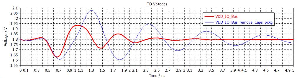

46 Time response comparison 4 ohm 1ns

47 PCB/PKG co-design PDN model PCB+PKG
48 TITLE REDUCING NOISE IN POWER DISTRIBUTION NETWORKS ON TIME AND ON BUDGET Image Sam Chitwood Product Engineer Cadence Design Systems, Inc.

49 Simultaneous Switching Noise (SSN / SSO) - Both SI and PI must be considered simultaneously! - SSN is dominated by return path issues - SSN is grossly underestimated with SIonly analysis tools Ideal PDN Minimal SSN predicted Real PDN Actual significant SSN effects


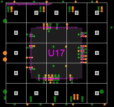
50 Signal Nets and PDN Which Tool to Use? Top Layer Bottom Layer Stack-up
51 Power Integrity and Signal Integrity! solid lines Circuit Analysis and 3DEM Analysis (channels and locally shorted planes, loss, slight impedance mismatch) dashed lines SI/PI Full-package Analysis (channel and full planes, includes power plane resonances) WARNING: A false sense of security is established if only circuit simulation is applied. If 3DEM simulation is later applied as a verification, this sense of security can be falsely reinforced if the full power planes are not included properly in the simulation.


52 DC / IR Drop Analysis Wizard-driven GUI and customizable workflows extremely easy for novice and occasional users Multi-fabric electrical + thermal co-simulation Automatically determine optimum VRM sense line locations for maximum system-level margin Electrical constraint management Power tree setup automation Detailed results and signoff reports

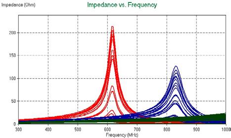
53 Decap Optimization - Impedance vs. Cost Red original impedance Blue optimized impedance at lower cost

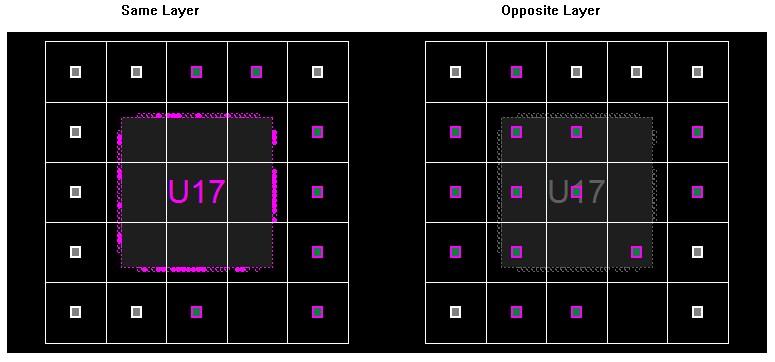
54 Add Decaps Intelligently Red No EMI decaps Blue 1 decap Green 3 decaps

55 PI Simulation from Within Layout Tools Enable the whole design process to be completed on time Constraint-driven decap design flow PI Constraint Sets guide PCB designer on decoupling cap placement Integrated DC analysis and design DRC markers resulting from analysis annotated to the layout Cross-probing between layout design and analysis results Decap back-annotation from simulation results to layout env. Batch mode to run analysis engine reduces the complexity of tools, more focus on problems Reuse analysis setup from PI expert What if Layout Engineers could do basic PI analysis? PI Experts could then focus on the fun simulations
56 Thank you! --- QUESTIONS?
Automotive PCB SI and PI analysis
 Automotive PCB SI and PI analysis SI PI Analysis Signal Integrity S-Parameter Timing analysis Eye diagram Power Integrity Loop / Partial inductance DC IR-Drop AC PDN Impedance Power Aware SI Signal Integrity
SSO Noise, Eye Margin, and Jitter Characterization for I/O Power Integrity
 DESIGNCON 2009 SSO Noise, Eye Margin, and Jitter Characterization for I/O Power Integrity Vishram S. Pandit, Intel Corporation [vishram.s.pandit@intel.com, (916)356-2059] Ashish N. Pardiwala, Intel Corporation
Power integrity is more than decoupling capacitors The Power Integrity Ecosystem. Keysight HSD Seminar Mastering SI & PI Design
 Power integrity is more than decoupling capacitors The Power Integrity Ecosystem Keysight HSD Seminar Mastering SI & PI Design Signal Integrity Power Integrity SI and PI Eco-System Keysight Technologies
Engineering the Power Delivery Network
 C HAPTER 1 Engineering the Power Delivery Network 1.1 What Is the Power Delivery Network (PDN) and Why Should I Care? The power delivery network consists of all the interconnects in the power supply path
Intro. to PDN Planning PCB Stackup Technology Series
 Introduction to Power Distribution Network (PDN) Planning Bill Hargin In-Circuit Design b.hargin@icd.com.au 425-301-4425 Intro. to PDN Planning 1. Intro/Overview 2. Bypass/Decoupling Strategy 3. Plane
Reliable World Class Insights Your Silicon Valley Partner in Simulation ANSYS Sales, Consulting, Training & Support
 www.ozeninc.com info@ozeninc.com (408) 732 4665 1210 E Arques Ave St 207 Sunnyvale, CA 94085 Reliable World Class Insights Your Silicon Valley Partner in Simulation ANSYS Sales, Consulting, Training &
Relationship Between Signal Integrity and EMC
 Relationship Between Signal Integrity and EMC Presented by Hasnain Syed Solectron USA, Inc. RTP, North Carolina Email: HasnainSyed@solectron.com 06/05/2007 Hasnain Syed 1 What is Signal Integrity (SI)?
Broadband Methodology for Power Distribution System Analysis of Chip, Package and Board for High Speed IO Design
 DesignCon 2009 Broadband Methodology for Power Distribution System Analysis of Chip, Package and Board for High Speed IO Design Hsing-Chou Hsu, VIA Technologies jimmyhsu@via.com.tw Jack Lin, Sigrity Inc.
Power Distribution Network Design for Stratix IV GX and Arria II GX FPGAs
 Power Distribution Network Design for Stratix IV GX and Arria II GX FPGAs Transceiver Portfolio Workshops 2009 Question What is Your PDN Design Methodology? Easy Complex Historical Full SPICE simulation
Signal Integrity Design of TSV-Based 3D IC
 Signal Integrity Design of TSV-Based 3D IC October 24, 21 Joungho Kim at KAIST joungho@ee.kaist.ac.kr http://tera.kaist.ac.kr 1 Contents 1) Driving Forces of TSV based 3D IC 2) Signal Integrity Issues
How to anticipate Signal Integrity Issues: Improve my Channel Simulation by using Electromagnetic based model
 How to anticipate Signal Integrity Issues: Improve my Channel Simulation by using Electromagnetic based model HSD Strategic Intent Provide the industry s premier HSD EDA software. Integration of premier
Considerations in High-Speed High Performance Die-Package-Board Co-Design. Jenny Jiang Altera Packaging Department October 2014
 Considerations in High-Speed High Performance Die-Package-Board Co-Design Jenny Jiang Altera Packaging Department October 2014 Why Co-Design? Complex Multi-Layer BGA Package Horizontal and vertical design
High Speed Design Issues and Jitter Estimation Techniques. Jai Narayan Tripathi
 High Speed Design Issues and Jitter Estimation Techniques Jai Narayan Tripathi (jainarayan.tripathi@st.com) Outline Part 1 High-speed Design Issues Signal Integrity Power Integrity Jitter Power Delivery
Picotest s Power Integrity Workshop
 Picotest s Power Integrity Workshop Course Overview In this workshop, taught by leading author ( Power Integrity -- Measuring, Optimizing and Troubleshooting Power Systems ) and Test Engineer of the Year
ANSYS CPS SOLUTION FOR SIGNAL AND POWER INTEGRITY
 ANSYS CPS SOLUTION FOR SIGNAL AND POWER INTEGRITY Rémy FERNANDES Lead Application Engineer ANSYS 1 2018 ANSYS, Inc. February 2, 2018 ANSYS ANSYS - Engineering simulation software leader Our industry reach
Power Plane and Decoupling Optimization. Isaac Waldron
 Power Plane and Decoupling Optimization p Isaac Waldron Overview Frequency- and time-domain power distribution system specifications Decoupling design example Bare board Added d capacitors Buried Capacitance
Target Impedance and Rogue Waves Panel discussion
 DesignCon 2016 Target Impedance and Rogue Waves Panel discussion Eric Bogatin, Teledyne LeCroy, moderator Istvan Novak, Oracle Steve Sandler, PicoTest Larry Smith, Qualcomm Brad Brim, Cadence the empty
PDN design and analysis methodology in SI&PI codesign
 PDN design and analysis methodology in SI&PI codesign www.huawei.com Asian IBIS Summit, November 9, 2010, Shenzhen China Luo Zipeng (luozipeng@huawei.com) Liu Shuyao (liushuyao@huawei.com) HUAWEI TECHNOLOGIES
Myoung Joon Choi, Vishram S. Pandit Intel Corp.
 Myoung Joon Choi, Vishram S. Pandit Intel Corp. IBIS Summit at DesignCon 2010 Acknowledgements: Woong Hwan Ryu, Joe Salmon Copyright 2010, Intel Corporation. All rights reserved. Need for SI/PI Co-analysis
Signal Integrity Modeling and Simulation for IC/Package Co-Design
 Signal Integrity Modeling and Simulation for IC/Package Co-Design Ching-Chao Huang Optimal Corp. October 24, 2004 Why IC and package co-design? The same IC in different packages may not work Package is
Si-Interposer Collaboration in IC/PKG/SI. Eric Chen
 Si-Interposer Collaboration in IC/PKG/SI Eric Chen 4/Jul/2014 Design Overview U-bump Logic IC Mem IC C4 bump Logic IC Silicon/Organic substrate Interposer Mem IC CAP Package substrate Solder Ball VRM BGA
DDR4 memory interface: Solving PCB design challenges
 DDR4 memory interface: Solving PCB design challenges Chang Fei Yee - July 23, 2014 Introduction DDR SDRAM technology has reached its 4th generation. The DDR4 SDRAM interface achieves a maximum data rate
Decoupling Capacitance
 Decoupling Capacitance Nitin Bhardwaj ECE492 Department of Electrical and Computer Engineering Agenda Background On-Chip Algorithms for decap sizing and placement Based on noise estimation Decap modeling
PDS Impact for DDR Low Cost Design
 PDS Impact for DDR3-1600 Low Cost Design Jack W.C. Lin Sr. AE Manager jackl@cadence.com Aug. g 13 2013 Cadence, OrCAD, Allegro, Sigrity and the Cadence logo are trademarks of Cadence Design Systems, Inc.
Taking the Mystery out of Signal Integrity
 Slide - 1 Jan 2002 Taking the Mystery out of Signal Integrity Dr. Eric Bogatin, CTO, GigaTest Labs Signal Integrity Engineering and Training 134 S. Wolfe Rd Sunnyvale, CA 94086 408-524-2700 www.gigatest.com
DesignCon On-Chip Power Supply Noise and Reliability Analysis for Multi-Gigabit I/O Interfaces
 DesignCon 2010 On-Chip Power Supply Noise and Reliability Analysis for Multi-Gigabit I/O Interfaces Ralf Schmitt, Rambus Inc. [Email: rschmitt@rambus.com] Hai Lan, Rambus Inc. Ling Yang, Rambus Inc. Abstract
Introduction to EMI/EMC Challenges and Their Solution
 Introduction to EMI/EMC Challenges and Their Solution Dr. Hany Fahmy HSD Application Expert Agilent Technologies Davy Pissort, K.U. Leuven Charles Jackson, Nvidia Charlie Shu, Nvidia Chen Wang, Nvidia
A Co-design Methodology of Signal Integrity and Power Integrity
 DesignCon 2006 A Co-design Methodology of Signal Integrity and Power Integrity Woong Hwan Ryu, Intel Corporation woong.hwan.ryu@intel.com Min Wang, Intel Corporation min.wang@intel.com 1 Abstract As PCB
A Resonance-Free Power Delivery System Design Methodology applying 3D Optimized Extended Adaptive Voltage Positioning.
 A Resonance-Free Power Delivery System Design Methodology applying 3D Optimized Extended Adaptive Voltage Positioning Tao Xu Brad Brim Agenda Adaptive voltage positioning (AVP) Extended adaptive voltage
Wideband On-die Power Supply Decoupling in High Performance DRAM
 Wideband On-die Power Supply Decoupling in High Performance DRAM Timothy M. Hollis, Senior Member of the Technical Staff Abstract: An on-die decoupling scheme, enabled by memory array cell technology,
EMI Reduction on an Automotive Microcontroller
 EMI Reduction on an Automotive Microcontroller Design Automation Conference, July 26 th -31 st, 2009 Patrice JOUBERT DORIOL 1, Yamarita VILLAVICENCIO 2, Cristiano FORZAN 1, Mario ROTIGNI 1, Giovanni GRAZIOSI
A Simulation Study of Simultaneous Switching Noise
 A Simulation Study of Simultaneous Switching Noise Chi-Te Chen 1, Jin Zhao 2, Qinglun Chen 1 1 Intel Corporation Network Communication Group, LOC4/19, 9750 Goethe Road, Sacramento, CA 95827 Tel: 916-854-1178,
Practical Limitations of State of the Art Passive Printed Circuit Board Power Delivery Networks for High Performance Compute Systems
 Practical Limitations of State of the Art Passive Printed Circuit Board Power Delivery Networks for High Performance Compute Systems Presented by Chad Smutzer Mayo Clinic Special Purpose Processor Development
Development and Validation of a Microcontroller Model for EMC
 Development and Validation of a Microcontroller Model for EMC Shaohua Li (1), Hemant Bishnoi (1), Jason Whiles (2), Pius Ng (3), Haixiao Weng (2), David Pommerenke (1), and Daryl Beetner (1) (1) EMC lab,
CIRCUITS. Raj Nair Donald Bennett PRENTICE HALL
 POWER INTEGRITY ANALYSIS AND MANAGEMENT I CIRCUITS Raj Nair Donald Bennett PRENTICE HALL Upper Saddle River, NJ Boston Indianapolis San Francisco New York Toronto Montreal London Munich Paris Madrid Capetown
Adding On-Chip Capacitance in IBIS Format for SSO Simulation
 Adding On-Chip Capacitance in IBIS Format for SSO Simulation Raymond Y. Chen SIGRITY, Inc. Jan. 2004 DesignCon 2004 - IBIS Summit Presentation Agenda 1. Is IBIS good for SSO simulation 2. SSO simulation
PDN Probes. P2100A/P2101A Data Sheet. 1-Port and 2-Port 50 ohm Passive Probes
 P2100A/P2101A Data Sheet PDN Probes 1-Port and 2-Port 50 ohm Passive Probes power integrity PDN impedance testing ripple PCB resonances transient step load stability and NISM noise TDT/TDR clock jitter
Thank you for downloading one of our ANSYS whitepapers we hope you enjoy it.
 Thank you! Thank you for downloading one of our ANSYS whitepapers we hope you enjoy it. Have questions? Need more information? Please don t hesitate to contact us! We have plenty more where this came from.
Ensuring Signal and Power Integrity for High-Speed Digital Systems
 Ensuring Signal and Power Integrity for High-Speed Digital Systems An EMC Perspective Christian Schuster Institut für Theoretische Elektrotechnik Technische Universität Hamburg-Harburg (TUHH) Invited Presentation
Design Considerations for Highly Integrated 3D SiP for Mobile Applications
 Design Considerations for Highly Integrated 3D SiP for Mobile Applications FDIP, CA October 26, 2008 Joungho Kim at KAIST joungho@ee.kaist.ac.kr http://tera.kaist.ac.kr Contents I. Market and future direction
Decoupling capacitor placement
 Decoupling capacitor placement Covered in this topic: Introduction Which locations need decoupling caps? IC decoupling Capacitor lumped model How to maximize the effectiveness of a decoupling cap Parallel
Simulation and Measurement of an On-Die Power-Gated Power Delivery System
 DesignCon 2010 Simulation and Measurement of an On-Die Power-Gated Power Delivery System Jimmy Huang, Intel [jimmy.huat.since.huang@intel.com, (+604)-2532385] Tan Fern Nee, Intel [fern.nee.tan@intel.com,
Advanced Topics in EMC Design. Issue 1: The ground plane to split or not to split?
 NEEDS 2006 workshop Advanced Topics in EMC Design Tim Williams Elmac Services C o n s u l t a n c y a n d t r a i n i n g i n e l e c t r o m a g n e t i c c o m p a t i b i l i t y e-mail timw@elmac.co.uk
Characterization of Alternate Power Distribution Methods for 3D Integration
 Characterization of Alternate Power Distribution Methods for 3D Integration David C. Zhang, Madhavan Swaminathan, David Keezer and Satyanarayana Telikepalli School of Electrical and Computer Engineering,
Evaluation of Package Properties for RF BJTs
 Application Note Evaluation of Package Properties for RF BJTs Overview EDA simulation software streamlines the development of digital and analog circuits from definition of concept and estimation of required
Design of the Power Delivery System for Next Generation Gigahertz Packages
 Design of the Power Delivery System for Next Generation Gigahertz Packages Madhavan Swaminathan Professor School of Electrical and Computer Engg. Packaging Research Center madhavan.swaminathan@ece.gatech.edu
DL-150 The Ten Habits of Highly Successful Designers. or Design for Speed: A Designer s Survival Guide to Signal Integrity
 Slide -1 Ten Habits of Highly Successful Board Designers or Design for Speed: A Designer s Survival Guide to Signal Integrity with Dr. Eric Bogatin, Signal Integrity Evangelist, Bogatin Enterprises, www.bethesignal.com
System Co-design and optimization for high performance and low power SoC s
 System Co-design and optimization for high performance and low power SoC s Siva S Kothamasu, Texas Instruments Inc, Dallas Snehamay Sinha, Texas Instruments Inc, Dallas Amit Brahme, Texas Instruments India
Low power SERDES transceiver for supply-induced jitter sensitivity methodology analysis
 Low power SERDES transceiver for supply-induced jitter sensitivity methodology analysis Micro Chang htc Michael_Chang@hTC.com Jan 9, 2019 X 1 Agenda Jitter-aware target impedance of power delivery network
W2360EP/ET SIPro Signal Integrity EM Analysis W2359EP/ET PIPro Power Integrity EM Analysis
 Keysight Technologies Advanced Design System (ADS) W2360EP/ET SIPro Signal Integrity EM Analysis W2359EP/ET PIPro Power Integrity EM Analysis Data Sheet Composite EM technology delivers high-accuracy and
Session 5 PCB Advancements And Opportunities
 Minimizing Socket & Board Inductance using a Novel decoupling Interposer 2007 Burn-in and Test Socket Workshop Nick Langston James Zhou, Hongjun Yao It is better to uncover a little than to cover a lot.
Effect of Aging on Power Integrity of Digital Integrated Circuits
 Effect of Aging on Power Integrity of Digital Integrated Circuits A. Boyer, S. Ben Dhia Alexandre.boyer@laas.fr Sonia.bendhia@laas.fr 1 May 14 th, 2013 Introduction and context Long time operation Harsh
Compensation for Simultaneous Switching Noise in VLSI Packaging Brock J. LaMeres University of Colorado September 15, 2005
 Compensation for Simultaneous Switching Noise in VLSI Packaging Brock J. LaMeres University of Colorado 1 Problem Statement Package Interconnect Limits VLSI System Performance The three main components
An Initial Case Study for BIRD95: Enhancing IBIS for SSO Power Integrity Simulation
 An Initial Case Study for BIRD95: Enhancing IBIS for SSO Power Integrity Simulation Also presented at the January 31, 2005 IBIS Summit SIGRITY, INC. Sam Chitwood Raymond Y. Chen Jiayuan Fang March 2005
Low Jitter, Low Emission Timing Solutions For High Speed Digital Systems. A Design Methodology
 Low Jitter, Low Emission Timing Solutions For High Speed Digital Systems A Design Methodology The Challenges of High Speed Digital Clock Design In high speed applications, the faster the signal moves through
Effect of Power Noise on Multi-Gigabit Serial Links
 Effect of Power Noise on Multi-Gigabit Serial Links Ken Willis (kwillis@sigrity.com) Kumar Keshavan (ckumar@sigrity.com) Jack Lin (jackwclin@sigrity.com) Tariq Abou-Jeyab (tariqa@sigrity.com) Sigrity Inc.,
Harmonic Comb Injector
 J2150A Data Sheet Harmonic Comb Injector Broadband EMI Signal Generator power integrity pdn interrogation EMI/EMC cable/chamber testing troubleshooting Picotest J2150A Harmonic Comb Data Sheet Page 2 Harmonic
PROCESS-VOLTAGE-TEMPERATURE (PVT) VARIATIONS AND STATIC TIMING ANALYSIS
 VARIATIONS AND STATIC TIMING ANALYSIS") PROCESS-VOLTAGE-TEMPERATURE (PVT) VARIATIONS AND STATIC TIMING ANALYSIS The major design challenges of ASIC design consist of microscopic issues and macroscopic issues [1]. The microscopic issues are ultra-high
PROCESS-VOLTAGE-TEMPERATURE (PVT) VARIATIONS AND STATIC TIMING ANALYSIS The major design challenges of ASIC design consist of microscopic issues and macroscopic issues [1]. The microscopic issues are ultra-high
ECEN689: Special Topics in High-Speed Links Circuits and Systems Spring 2012
 ECEN689: Special Topics in High-Speed Links Circuits and Systems Spring 2012 Lecture 5: Termination, TX Driver, & Multiplexer Circuits Sam Palermo Analog & Mixed-Signal Center Texas A&M University Announcements
TITLE. Image. Topic: Topic: Hee-Soo o LEE, Keysight Technologies Cindy Cui, Keysight Technologies
 TITLE Topic: Accurate o Nam elementum Statistical-Based commodo mattis. Pellentesque DDR4 Margin Estimation using malesuada SSN blandit Induced euismod. Jitter Model Topic: Hee-Soo o LEE, Keysight Technologies
EMC cases study. Antonio Ciccomancini Scogna, CST of America CST COMPUTER SIMULATION TECHNOLOGY
 EMC cases study Antonio Ciccomancini Scogna, CST of America antonio.ciccomancini@cst.com Introduction Legal Compliance with EMC Standards without compliance products can not be released to the market Failure
Chip Package - PC Board Co-Design: Applying a Chip Power Model in System Power Integrity Analysis
 Chip Package - PC Board Co-Design: Applying a Chip Power Model in System Power Integrity Analysis Authors: Rick Brooks, Cisco, ricbrook@cisco.com Jane Lim, Cisco, honglim@cisco.com Udupi Harisharan, Cisco,
04/29/03 EE371 Power Delivery D. Ayers 1. VLSI Power Delivery. David Ayers
 04/29/03 EE371 Power Delivery D. Ayers 1 VLSI Power Delivery David Ayers 04/29/03 EE371 Power Delivery D. Ayers 2 Outline Die power delivery Die power goals Typical processor power grid Transistor power
Performance Improvement by System Aware Substrate Noise Analysis for Mixed-signal IC
 DesignCon 2017 Performance Improvement by System Aware Substrate Noise Analysis for Mixed-signal IC Kwangseok Choi, Samsung Electronics Inc. [aquarian505@gmail.com] Byunghyun Lee, Samsung Electronics Inc.
EMI Modeling of a 32-bit Microcontroller in Wait Mode
 EMI Modeling of a 32-bit Microcontroller in Wait Mode Jean-Pierre Leca 1,2, Nicolas Froidevaux 1, Henri Braquet 2, Gilles Jacquemod 2 1 STMicroelectronics, 2 LEAT, UMR CNRS-UNS 6071 BMAS 2010 San Jose,
Optimizing On Die Decap in a System at Early Stage of Design Cycle
 Optimizing On Die Decap in a System at Early Stage of Design Cycle Naresh Dhamija Pramod Parameswaran Sarika Jain Makeshwar Kothandaraman Praveen Soora Disclaimer: The scope of approach presented is limited
Vishram S. Pandit, Intel Corporation (916) ]
![Vishram S. Pandit, Intel Corporation (916) ]](/thumbs/72/66540527.jpg "Vishram S. Pandit, Intel Corporation (916) ]") DesignCon 2008 Simulation and Characterization of GHz On-Chip Power Delivery Network (PDN) Vishram S. Pandit, Intel Corporation [vishram.s.pandit@intel.com, (916)356-2059] Woong Hwan Ryu, Intel Corporation
DesignCon 2008 Simulation and Characterization of GHz On-Chip Power Delivery Network (PDN) Vishram S. Pandit, Intel Corporation [vishram.s.pandit@intel.com, (916)356-2059] Woong Hwan Ryu, Intel Corporation
Chapter 16 PCB Layout and Stackup
 Chapter 16 PCB Layout and Stackup Electromagnetic Compatibility Engineering by Henry W. Ott Foreword The PCB represents the physical implementation of the schematic. The proper design and layout of a printed
MPC 5534 Case study. E. Sicard (1), B. Vrignon (2) Toulouse France. Contact : web site :
, B. Vrignon (2) Toulouse France. Contact : web site :") MPC 5534 Case study E. Sicard (1), B. Vrignon (2) (1) INSA-GEI, 135 Av de Rangueil 31077 Toulouse France (2) Freescale Semiconductors, Toulouse, France Contact : etienne.sicard@insa-toulouse.fr web site
MPC 5534 Case study E. Sicard (1), B. Vrignon (2) (1) INSA-GEI, 135 Av de Rangueil 31077 Toulouse France (2) Freescale Semiconductors, Toulouse, France Contact : etienne.sicard@insa-toulouse.fr web site
Experience at INFN Padova on constrained PCB design Roberto Isocrate INFN-Padova
 Experience at INFN Padova on constrained PCB design Roberto Isocrate INFN-Padova Experience at INFN Padova on constrained design 1. Why do we need Signal Integrity (SI) analysis (and constrained design)?
EECS 473 Advanced Embedded Systems. Lecture 9: Groups introduce their projects Power integrity issues
 EECS 473 Advanced Embedded Systems Lecture 9: Groups introduce their projects Power integrity issues Project groups Please give a 2-3 minute overview of your project. Half the groups will do this each
LSI and Circuit Technologies for the SX-8 Supercomputer
 LSI and Circuit Technologies for the SX-8 Supercomputer By Jun INASAKA,* Toshio TANAHASHI,* Hideaki KOBAYASHI,* Toshihiro KATOH,* Mikihiro KAJITA* and Naoya NAKAYAMA This paper describes the LSI and circuit
Understanding, measuring, and reducing output noise in DC/DC switching regulators
 Understanding, measuring, and reducing output noise in DC/DC switching regulators Practical tips for output noise reduction Katelyn Wiggenhorn, Applications Engineer, Buck Switching Regulators Robert Blattner,
EMC analysis workflow
 EMC analysis workflow Antonio Ciccomancini Scogna, CST of America antonio.ciccomancini@cst.com EMC/EMI Applications Emissions Susceptibility E3 Typical Emissions Issues 1 2 Image courtesy of Johnson Controls
Di/dt Mitigation Method in Power Delivery Design & Analysis
 Di/dt Mitigation Method in Power Delivery Design & Analysis Delino Julius Thao Pham Fattouh Farag DAC 2009, San Francisco July 27, 2009 Outlines Introduction Background di/dt Mitigation Modeling di/dt
EECS 473 Advanced Embedded Systems. Lecture 9: Groups introduce their projects Power integrity issues
 EECS 473 Advanced Embedded Systems Lecture 9: Groups introduce their projects Power integrity issues Final proposal due today Final proposal I should have signed group agreement now. I should have feedback
Implementation of Power Transmission Lines to Field Programmable Gate Array ICs for Managing Signal and Power Integrity
 Implementation of Power Transmission Lines to Field Programmable Gate Array ICs for Managing Signal and Power Integrity Sang Kyu Kim, Satyanarayana Telikepalli, Sung Joo Park, Madhavan Swaminathan and
Quick guide to Power. V1.2.1 July 29 th 2013
 Quick guide to Power Distribution ib ti Network Design V1.2.1 July 29 th 2013 High level High current, high transient Power Distribution Networks (PDN) need to be able to respond to changes and transients
Signal Technologies 1
 Signal Technologies 1 Gunning Transceiver Logic (GTL) - evolution Evolved from BTL, the backplane transceiver logic, which in turn evolved from ECL (emitter-coupled logic) Setup of an open collector bus
TITLE. Capturing (LP)DDR4 Interface PSIJ and RJ Performance. Image. Topic: Topic: John Ellis, Synopsys, Inc. Topic: malesuada blandit euismod.
DDR4 Interface PSIJ and RJ Performance. Image. Topic: Topic: John Ellis, Synopsys, Inc. Topic: malesuada blandit euismod.") TITLE Topic: o Nam elementum commodo mattis. Pellentesque Capturing (LP)DDR4 Interface PSIJ and RJ Performance malesuada blandit euismod. Topic: John Ellis, Synopsys, Inc. o o Nam elementum commodo mattis.
TITLE Topic: o Nam elementum commodo mattis. Pellentesque Capturing (LP)DDR4 Interface PSIJ and RJ Performance malesuada blandit euismod. Topic: John Ellis, Synopsys, Inc. o o Nam elementum commodo mattis.
How to Design Good PDN Filters
 How to Design Good PDN Filters Istvan Novak, Samtec This session was presented as part of the DesignCon 2019 Conference and Expo. For more information on the event, please go to DesignCon.com 1 How to
EMI. Chris Herrick. Applications Engineer
 Fundamentals of EMI Chris Herrick Ansoft Applications Engineer Three Basic Elements of EMC Conduction Coupling process EMI source Emission Space & Field Conductive Capacitive Inductive Radiative Low, Middle
DesignCon Effect of Power Plane Inductance on Power Delivery Networks. Shirin Farrahi, Cadence Design Systems
 DesignCon 2019 Effect of Power Plane Inductance on Power Delivery Networks Shirin Farrahi, Cadence Design Systems shirinf@cadence.com, 978-262-6008 Ethan Koether, Oracle Corp ethan.koether@oracle.com Mehdi
Modeling System Signal Integrity Uncertainty Considerations
 white paper Intel FPGA Modeling System Signal Integrity Uncertainty Considerations Authors Ravindra Gali High-Speed I/O Applications Engineering, Intel Corporation Zhi Wong High-Speed I/O Applications
LP3120. White LED Backlighting Li-Ion Battery Backup Supplies Local 3V to 5V Conversion Smart Card Readers PCMCIA Local 5V Supplies
 http://www.szczkjgs.com LP3120 Low Noise, Regulated Charge Pump DC/DC Converter Features Fixed 5V ± 4% Output VIN Range: 2.5V to 5V Output Current: Up to 250mA Constant Frequency Operation at All Loads
An Active Decoupling Capacitance Circuit for Inductive Noise Suppression in Power Supply Networks
 An Active Decoupling Capacitance Circuit for Inductive Noise Suppression in Power Supply Networks Sanjay Pant, David Blaauw University of Michigan, Ann Arbor, MI Abstract The placement of on-die decoupling
Low Power Design Methods: Design Flows and Kits
 JOINT ADVANCED STUDENT SCHOOL 2011, Moscow Low Power Design Methods: Design Flows and Kits Reported by Shushanik Karapetyan Synopsys Armenia Educational Department State Engineering University of Armenia
Microcircuit Electrical Issues
 Microcircuit Electrical Issues Distortion The frequency at which transmitted power has dropped to 50 percent of the injected power is called the "3 db" point and is used to define the bandwidth of the
Signal Integrity Tips and Techniques Using TDR, VNA and Modeling. Russ Kramer O.J. Danzy
 Signal Integrity Tips and Techniques Using TDR, VNA and Modeling Russ Kramer O.J. Danzy Simulation What is the Signal Integrity Challenge? Tx Rx Channel Asfiakhan Dreamstime.com - 3d People Communication
High Speed Digital Design & Verification Seminar. Measurement fundamentals
 High Speed Digital Design & Verification Seminar Measurement fundamentals Agenda Sources of Jitter, how to measure and why Importance of Noise Select the right probes! Capture the eye diagram Why measure
Signal integrity means clean
 CHIPS & CIRCUITS As you move into the deep sub-micron realm, you need new tools and techniques that will detect and remedy signal interference. Dr. Lynne Green, HyperLynx Division, Pads Software Inc The
SUBSTRATE NOISE FULL-CHIP LEVEL ANALYSIS FLOW FROM EARLY DESIGN STAGES TILL TAPEOUT. Hagay Guterman, CSR Jerome Toublanc, Ansys
 SUBSTRATE NOISE FULL-CHIP LEVEL ANALYSIS FLOW FROM EARLY DESIGN STAGES TILL TAPEOUT Hagay Guterman, CSR Jerome Toublanc, Ansys Speakers Hagay Guterman, CSR Hagay Guterman is a senior signal and power integrity
PCB Routing Guidelines for Signal Integrity and Power Integrity
 PCB Routing Guidelines for Signal Integrity and Power Integrity Presentation by Chris Heard Orange County chapter meeting November 18, 2015 1 Agenda Insertion Loss 101 PCB Design Guidelines For SI Simulation
Active and Passive Techniques for Noise Sensitive Circuits in Integrated Voltage Regulator based Microprocessor Power Delivery
 Active and Passive Techniques for Noise Sensitive Circuits in Integrated Voltage Regulator based Microprocessor Power Delivery Amit K. Jain, Sameer Shekhar, Yan Z. Li Client Computing Group, Intel Corporation
Guaranteeing Silicon Performance with FPGA Timing Models
 white paper Intel FPGA Guaranteeing Silicon Performance with FPGA Timing Models Authors Minh Mac Member of Technical Staff, Technical Services Intel Corporation Chris Wysocki Senior Manager, Software Englineering
DesignCon FPGA I/O Timing Variations Due to Simultaneous Switching Outputs. Zhe Li, Altera Corporation
 DesignCon 2008 FPGA I/O Timing Variations Due to Simultaneous Switching Outputs Zhe Li, Altera Corporation ZLI@altera.com, 408-544-7762 Iliya Zamek, Altera Corporation izamek@altera.com, 408-544-8116 Peter
High Speed Digital Systems Require Advanced Probing Techniques for Logic Analyzer Debug
 JEDEX 2003 Memory Futures (Track 2) High Speed Digital Systems Require Advanced Probing Techniques for Logic Analyzer Debug Brock J. LaMeres Agilent Technologies Abstract Digital systems are turning out
Enhancing Analog Signal Generation by Digital Channel Using Pulse-Width Modulation
 Enhancing Analog Signal Generation by Digital Channel Using Pulse-Width Modulation Angelo Zucchetti Advantest angelo.zucchetti@advantest.com Introduction Presented in this article is a technique for generating
CAPLESS REGULATORS DEALING WITH LOAD TRANSIENT
 CAPLESS REGULATORS DEALING WITH LOAD TRANSIENT 1. Introduction In the promising market of the Internet of Things (IoT), System-on-Chips (SoCs) are facing complexity challenges and stringent integration
Unleash SiC MOSFETs Extract the Best Performance
 Unleash SiC MOSFETs Extract the Best Performance Xuning Zhang, Gin Sheh, Levi Gant and Sujit Banerjee Monolith Semiconductor Inc. 1 Outline SiC devices performance advantages Accurate test & measurement