UP30 UAV Autopilot System Manual Version 5.7
|
|
|
- Francis Allen
- 6 years ago
- Views:
Transcription

1 UP30 UAV Autopilot System Manual Version
2 CONTENTS Warning, warranty and upgrade Warning Warranty Upgrade Contact Introduction to UP30 Autopilot System Onboard Autopilot system Introduction Features... 6 Physical parameters Environment Power... 9 Connection diagram Installation of UP Power RC Receiver Setting RC Transmitter Flight Control mode Servo GPS Data Link Pitot Barometer Engine Rotate Sensor Deadline switch Throttle setting Gyro Checking the installation of UP Ground station software Introduction Minimum system configuration Interface description Setting a dialog box Photography Camera Gimbal Capture operation Downlink data PID channel Map Route
3 Automatic route generation Pattern routes Navigation mode and navigation logic Automatic landing route Immediate route mode Tools Installation Wizard Checking before take-off Flight control CPV flight control CRPV flight operations Flight recording and playback Alarm Files and folders Flight Operations Emergency Management Realizing automatic control flight steps.. Flight test - 2 -
4 Warning, Warranty and Upgrade Warning UP30 system is forbidden to use for any illegal purposes, our company will not be responsible for any illegal uses, and will not bear the third- party liabilities caused by the uses of this system. This manual has the copyright, and it is protected by copyright. Any amendment, extract and publishment is forbidden. This manual may has some differences with the actual functions, and we do not guarantee that there is no mistakes in this manual. The information in this manual is subject to the changes without notice. All rights reserved. Warranty The warranty period of this product is 1 year (from the date of purchase). Normally if the product has quality problems, we will repair the product for free. If the damage due to abnormal use or rough use, the cost of materials will be charged. If the warranty period expiries, we will charge the cost of materials. If the damage caused by force majeure, we will charge the cost of materials. In other cases which are not included in the above mentioned situations, and it is can be repaired, we will only charge materials fee. Upgrade We will provide free upgrade service for Ground Control Station(GCS) software and UP30 firmware. Contact +086 (512) jennerjiang@gmail.com - 3 -
5 Introduction to UP30 Autopilot System UP30 autopilot system is a high-performance and low-cost UAV control system, which including autopilot, ground stations software, communications equipment. It can control UAV with various layout, it is easy to use, and have high control precision. GPS navigation has better automatic flight function. You can set the flight speed and flight altitude. There are a variety of task interfaces to connect users equipments. It can automatically control the UAV when take-off to landing. We can freely set flight routes and waypoints at the ground station, and we can change waypoints and target waypoint when flying. In addition, there are many security protection programs to make the maximum guarantee to UAV safe flight and failure protection. Using the UP30 autopilot system requires the following steps: 1. Familiar with the UP30 autopilot system 2. Master ground station software 3. Install onboard autopilot system 4. Set correctly installation parameters 5. Check the installation and ground testing 6. Pre-flight check 7. Flying and adjust the PID parameters - 4 -
6 Onboard Flight Control System Introduction Onboard autopilot system is installed in the aircraft, which including flight control panel (box), communications equipment, RC receiver, battery, GPS antenna, communication antenna, pitot. Correct installation of these components is very important, it must strictly follow the installation steps to install and test. Features 3-axis MEMS accelerometers integrated, rate gyros, high sensitivity GPS, digital pressure altimeter, airspeed sensor; Dual CPUs working together, strong processing ability; 16-bit AD for sensor acquisition and data accuracy; Altitude maintained, speed maintained, GPS navigation; Supporting the mix of flap, V tail, flying wing and flaperon; Automatic fixed-time and fixed-distance photography, automatically electronic shutter or servo controlled shutter; 2-axis ortho platform control makes aerial orthophotos better; The storage and download of pictures positions data convince that computer automatically puzzles; Fully integrated, light weight, low power consumption and small size 5 flight controlled servos, 1 parachute servo, 2 task servos, 2 user-defined servos; 5 flight modes: RC, RPV, UAV, CPV, CRPV; multiple IO, UART, SPI, I2C data task interfaces; 100 flight waypoints, each point can be set to one of 7 standard flight - 5 -
7 modes, standard time can be set; Waypoint data can be modified while flying, the target destinations can be modified timely; It has the flying modes of flying along the lines and flying obliquely between waypoints; 4HzGPS navigation speed controls and realizes more specific flight routes; 9 PID channels control aircraft s stable flight and its navigation, all parameters can be changed when flying; A variety of security models can be set; Battery voltage and GPS positioning can be monitored, engine speed can be monitored as well; Free software updates make you get more new and enhanced features; UP30 s power supply range is extended to 4 ~ 26V, most of electric planes can power it directly; UP 30 is smaller than UP20, only 40X100X12 mm 3, weighs 26g; Flexible external interfaces and task functions can be customized 3-axis electronic compass can be built to support the 3-axis PTZ control; UP 30 will have GPS / INS inertial navigation, so as to return to the take-off point in case of lost of stars; Servo is developed to 10 servos, which perform flight control and other tasks respectively; UP 30 supports low-speed radio communication (minimum baud rate to 1200bps), which makes communication distance more longer, more reliable, and less errors; 2 ~ 6 10-bit A/D channels & one 16-bit A/D channel Air data probing capabilities can observe the pressure and temperature of the wet air and wind speed (matching proper sensor); UP 30 have a 2-way speed monitoring, which is particularly suitable for - 6 -
8 the speed monitoring of twin-engine UAV, unmanned airship; New electrical stop function supports not only the former magnetic motor engine (such as Komatsu series), but also CDI ignition engines (such as 3w, etc.) UP 30 supports automatic parachute, and it can be connected with ultrasonic height sensor to achieve fully automatic landing roll, it only needs to designate the landing point, direction and circled round at the ground station, flight control will automatically calculate to find out the glide path. UP 30 supports the automatic take-off in many ways; UP 30 uses a new generation of GPS module with 50 channels, sensitive receiver of-160db, cold start positioning requires only 29 seconds, has the locating capability with multiple positioning sources, such as the GPS, GALILEO, SBAS etc. Software settings support the installation of 24 directions RC receiver s type can be defined by the users. UP 30 has a larger capacity to record 2,978 pos data of photos. Physical parameters Weight Flight Control Board (including GPS Receiver) weighs 26 grams Flight Control Box (including the flight control board, interface board) weighs 185 grams Size Flight Control Board is 100mmX40mmX16mm, with enclosure is 103mmX50mmX40mm Use of the environment Temperature: -25 to +70 C - 7 -
9 humidity: 5% to 95% (non-condensing) Power main power: 4V to 26V input range servo: voltage range 4.8V to 7V with 1w transceiver: main power, servo power monitoring - 8 -
10 Flight Control Box Interface Diagram Engine shutdown Camera control Rotational Rotational speed 1 speed 0 Power P-10 P-13 P-11 P-12 P-14 RC signal input P-7 Servos Serial communication port Servo Power - 9 -
11 Installation of UP30 The flight control box is installed near the center of the plane (as shown) with sponge packed or spring hanging for shock absorption, so as to avoid the flight control box directly touching any part of the fuselage. When installing aircraft engine, it is the best way to put the rubber gasket for shock absorption. Flight Control Box in the aircraft body can be installed in 24 directions to facilitate the installation, according to the interior space of the body. You only need to pay attention to the axis of the autopilot is mostly in conformity with the axis of the aircraft body. After finishing the installation of autopilot you shall go to the ground station to select "Settings -> Install Settings" in the menu, select the axis of the autopilot and the corresponding axis of the aircraft body as shown in the pictures. After choosing right 3-axis, installation code will appear, then you shall press "Settings." Autopilot must be re-powered to make the settings take effect

12 After finishing installation, you shall put the aircraft in a horizontal position, (you can observe the level bubble), choose Pitch/Roll in the Settings Dialog Box at the ground station, and click "Settings", so that the flight control will set the current status of the aircraft as a horizontal status. Clicking the "Gain " you can get the current installation position and the angle between the current horizontal position with the standard horizontal position of the factory
13 calibration. Clicking the " bias clear " you can restore the factory settings on the horizontal position. In this manual all aircrafts are distinguished its left and right by standing at the back of the aircraft and looking towards the head of aircraft. If you get the version of flight control has optional directions, you just need to set correct installation direction at ground station when you finishing installation. But if your version of flight control does not support optional directions, and you need to change installation direction in the fuselage, please contact the seller. About the ground station operation in this section please refer to the relevant parts of ground station software. As all electronic components are sensitive to temperature, when you install flight control box you have to reduce the external heating, such as direct sunlight, the heat from engines. In addition, the air pressure in aircraft cabin must keep stable and avoid the propeller blowing air directly to the flight control compartment, otherwise the instable static pressure will result in barometric altimeter and airspeed meter beating. Power The main power supply of flight control is DC 4V to 26V (if using a supporting digital radio of 1200bps, please choose the 7 ~ 10V power supply). Servo s power supply is 4.8V to 6V. The two groups of power supply have power monitors, please charge the battery before each flight to make sure that it has enough power. When connecting the main power supply and servo s power supply, do pay attention to the positive and the negative are connected correctly, or the Flight Control and the Servo may be burn out
14 Remote Receiver If your flight control (autopilot) must use receiver, the receiver must be properly connected and be packed with sponge for shock absorption. UP30 flight control (autopilot) must use FutabaPCM1024 or Futaba2.4G or JR Series 6-channel (or more) remote controller and receiver. Distance test by remote controller (PCM1024 remote controlled transmitter does not pull out its antenna, 2.4G remote controller selects low-power transmission mode for distance test), is able to reach more than 20 meters long. The receiver is connected properly as shown. The receiver must be connected from 1 to 6 channels regardless of the number of channels of the remote controller has. Follow the following cable to connect the receiver according to the number marked on the receiver s channels. CH4 is the plug for power supply, the rest are plugs for signal wires. Receiver Wire No. Original function New features CH1 1 Aileron Aileron, rudder, Or RPV turning instructions CH2 2 Elevator Elevator or a high degree of instruction RPV CH3 3 Throttle Engine or control, or ESC, RPV speed command CH4 4 Rudder Rudder or aileron +5V 5 The Positive from the
15 servo GND 6 The negative from the servo CH5 7 Landing gear Switch RC, RPV, UAV flight control modes CH6 8 AUX Control umbrella, flaps, rudder mission, launched one of the data transmission Because some interface boards use 5V power which is supplied by the flight control board for the receiver, so please do not connect servos directly with the rest channels of the receiver. But you can plug the 1 st and 3 rd pins of the servo (2 nd pin is for the positive power supply), you can receive the remote signals from the rest channels of the servo. The power of servo is supplied by the external power, so as to fulfill the utilization of the extra remote channels. For the case that some interface boards use directly the servo s power supply for the receiver, the extra channels of the receiver can be directly connected to the servo. Please contact the company for your interface board type. Setting Remote Controller The autopilot system must use FutabaPCM1024 or Futaba 2.4GHz proportional RC controller: Setting steps: 1 Choose a standard mode or restore the factory settings and set it to be the mode of fixed-wings; 2 Cancel all settings on the mixed control and cross-linked set in the remote controller. The mixed control
16 is set and controlled by the flight control (autopilot); 3 When using the Futaba remote controller you shall cancel all reverse settings of the servo, when using the JR remote controller, you shall set the 1 st to 6 th channels to be in reverse mode. The final reverse set of servo is controlled by the ground station; 4 Set the two-way trip of the 5 th channel s switch to be 100%. 5 Turn the 5 th channel s switch back towards the operator, and set the fail-safe mode of the 5 th channel as the rudder amount (fail-safe display should be about -92%, the corresponding mode is the UAV mode). 6 Reduce the trip of turning the 5 th channel s switch back towards the operator to 30%, the corresponding mode is the RPV mode; when the trip of turning the 5 th channel s switch back towards the operator is 100%, the corresponding mode is the RC mode. If you do not need RPV to adjust the flight mode, you do not need to set the 30% of the RPV mode. 7 According to the actual needs of remote controlled flight, the 1 st, 2 nd, 3 rd, 4 th channels in the remote controller can be set to be the servo s trip. When installing the servo, you should try your best to use the whole trip of the servo, and try your best to keep the neutral position of control surface consistent with the servo neutral position. The 5 th channel setting table: Direction Setting Volume Features Backward Fail-safe -100% Turn-off or out of control and turn into the UAV
17 remote controlled flight mode Backward normal operation 30% Turn into the RPV mode Forward normal operation 100% Turn into the RC mode When setting the 5 th channel s fail-safe mode, other failure modes of all channels are set to be remain. After finishing all sets, please observe the actual operation by watching the control mode displayed on the ground station. The 6 th channel in the remote controller is a multifunction channel, its specific function is set by the ground station, the absent is for the control of parachute (S6). The 1 st channel in the remote controller is optional for the need of control surface, if it the aircraft has aileron and rudder, the operator can choose the 1 st channel to control the surface of aileron according to his usual practice,; if the aircraft has aileron only, the operator can choose the 1 st channel to control aileron, if the aircraft has rudder only, the operator can choose the 1 st channel to control rudder. (Referring to ground station software settings -> Servo) Forward means facing the operator, backward means facing the back of remote controller. Flight Control Modes UP30 has five flight control modes: RC (radio control mode) RC is same with the usual remote control, it directly control every corresponding servo. It is often used in the landing and take-off, and PID parameters adjustment. RPV (command remote control mode) There are three commands in RPV mode, the aileron stick controls altitude, the elevator stick controls altitude, the throttle stick controls airspeed, and it is deferent with RC mode which controls the servo directly. Stable flying is automatically completed by Flight Control System
18 All the above control values take the neutral control value recorded in level flight as zero. The gap deviating from the zero is transferred to the deviating command value. Then the target height and airspeed should be the pre-defined neutral target value adding the deviating command value. The target bank angel is the deviating command value of aileron stick. Usually RPV mode is mainly used to set a fixed target when adjusting PID. When you switch remote controller to be in RPV mode from RC mode (typically the bar keeps still), you can observe the flying aircraft, if the aircraft goes into a dangerous status you can instantly switch the remote controller back to RC mode, then the aircraft will be back to the stable flight by hand operation. UAV (waypoints navigation mode) Turning off the remote controller or receiver will make the aircraft s flight controlled by GPS according to the pre-set waypoints. Setting some properties to waypoints can produce several different ways of navigation. CPV (computer remote control mode) Before entering CPV control mode, you need to set the required flight height and speed firstly. A manual switchover is made from UAV-CPV to CPV, the button turns red, and shows CPV. You also can input the course or press the button of CPV, then click on the map, the aircraft will immediately fly according to the course which is made of the current waypoint and the waypoints you has set. CRPV (joystick remote control mode) Before entering CRPV control mode, you need to set the required flight height and speed firstly. After the joystick is well connected, the CRPV flight control window will appear by pressing CRPV. A manual switchover is made from UAV-CRPV to CRPV, the button shows CRPV. If you use 1200BPS low-speed radio, you need to press the button of Stop Download to stop the transmission of aircraft downlink data. Ticking Effective Control the operation of joystick will continuing transmit to the aircraft. The left bar controls the movement of PTZ and the servo, and the right bar controls target turning angle
19 If the aircraft is in the modes of CPV or CRPV, losing communication for more than 20 seconds, The remote controller ( 主语是什么 ) will automatically switch to UAV flight mode. Note: CPV mode is to control the aircraft s flying at a set course and not to set destinations Servo Servo is connected out from the interface board, when installing servos, the remote controller should keep neutral, you should try your best to keep the servo arms perpendicular to linkage bar and keep the angle of servo perpendicular to linkage bar. According to the different layout of the aircraft, the channel connected to servo is different, the cross-linked settings are different. Please refer to the following table: Layout and servo configuration: Layout General layout? Upright & Flying wing, no tail inverted V tail Cross-linked set none Rudder - elevator Aileron - elevator CH1 Aileron Aileron Differential 1 CH2 elevator Differential 1 Differential 2 CH3 Throttle Throttle Throttle CH4 Rudder Differential 2 Direction or not CH5 Flap Flap Flap CH6 Parachute Parachute Parachute CH7 Multifunction Multifunction Multifunction CH8 Multifunction Multifunction Multifunction CH9 Multifunction Multifunction Multifunction CH10 Multifunction Multifunction Multifunction
20 Autopilot can control the aircraft s automatic turning in two ways. First: If using corner velocity to control automatic turning, the automatic control for turning outputs from the 4 th channel, and is to control rudder. Second: If using bank angle to control automatic turning, the turning is accomplished by ailerons, the rudder plugs the 4 th channel. If the aircraft has no ailerons, the rudder plugs the 1 st channel. Note: In RC mode, the 1 st channel of the remote controller (the right bar) is to control the rudder or ailerons, it can be set in the Settings Dialog Box at the ground station. If the aircraft has ailerons and rudder both, the operator can choose the 1 st channel to control ailerons and rudder according to his usual practice, if the aircraft has ailerons only, the operator should choose the 1 st channel to control ailerons, if the aircraft has rudder only, the operator should choose the 1 st channel to control rudder. When using flaperons mixing mode, S1 and S5 output respectively two servo signals, which is to control the two aileron servos. Pay attention that when the output value of flag reaches its maximum, the different value of the aileron will fail. After the remote controller is well set, if the movement of some channels of the servo is not correct and when the data of servo is downloading at the ground station, you should press the reverse button of the corresponding channel. The two task servos have two control modes: The first control mode has 2 appointed positions. You can set the 6 th channel to be a task servo, in the RC mode, you can control the servo to a specific position by the knob of the 6 th channel, then you press the corresponding button in the servo setting toolbar at the ground station, record this specific position as Location 0, then record anther position as Location 1 in the same way. After turning off the remote controller you can operate Test or press Button 0 or Button 1 in the Task Control Dialogue Box at the ground station to test the settings. The mode can serve as a launch or start a device. In setting waypoints, you can appoint the arrival waypoint and control the servo to go to the
21 appointed position automatically. Parachute servo (S6) is similar with it. You have to pre-set two specific positions for the parachute, and the automatic open of parachute will be executed correctly. The second control mode is a continuing control mode. In this mode you can control the position of the servo timely by scroll bar in the Task Dialog Box (or keyboard, joystick), such as the control of PTZ. GPS UP30 flight control must use the GPS with antenna. SMA interface (hole) is on the top of Flight Control Box, so the GPS antenna must use SMA plug (pin). Do not attempt to change the GPS antenna feeder s length, The feeder s length of the manufacturer is designed to match to GPS antenna. If you need a short antenna you can order the length of the antenna s feeder that you need. The installation position and the installation methods of GPS antenna will affect the quality of positioning. Please install GPS antenna according to the following methods. install a piece of "ground " You can use a metal plate with the size of 10cmX10cm as the ground, and attract GPS antenna to the metal plate, by doing so the GPS will have better signals. If the Flight Control Box is made of metal and have enough space, you can attract GPS antenna to the Flight Control Box directly. But if you can not use a metal plate as the ground, you can affix an aluminized paper or a silver paper at the bottom of the antenna. Pay attention to fix the GPS well in order to avoid GPS antenna falling to the place that GPS can not receive satellite signals. GPS antenna can be closer to the Flight Control Box. It makes that the GPS measured speed is as much as possible consistent with the speed of inertial sensors. Avoid obstacles Do not have any mental object to block the GPS antenna towards the sky, any little block will reduce the weak signals, for example, do not close
22 to any parts of the engine. Composite materials and wood aircraft body and wings has no effect on GPS signals. avoid other interference with signals GPS s signal frequency is 1.575G, and it is very weak and susceptible to electromagnetic interference, such as data transmission modem, especially those working poor 1.2G frequency microwave video transmission equipment. While testing on the ground, these disturbances may not affect the complete loss of GPS s positioning, but may result in the loss of GPS s positioning when flying. Localization quality can be seen in the ground station number and level of effective positioning satellite mass (PDOP). In the case of GPS antenna has no interference, it is generally about 40 seconds from the GPS s opening to its positioning, if the GPS s positioning takes a long time at the ground station, there may be some interference or GPS antenna is not connected well. Data Transmission Module If the UP30 flight control system that you purchased is the external data transmission module, please use the sponge to pack it for shock absorption, and connect with the module with a plug. The transmitter s antenna should be away from servo s signal wire, the flight control box and the antennal of remote control receive as far as possible depending on whether it interferes with these devices or not. In order to achieve the best communication distance, please install the antenna vertically downward or upward, and do not have any metal objects to close to the antenna. You can observe the numbers of effective satellite and PDOP at the ground station to evaluate the positioning accuracy of the horizontal coordinate. The output signals of the autopilot is RS232 serial signals, and if you need to configure data transmission module of the TTL interface, please state when you purchase
23 Pitot You can use a metal pipe or arrow shaft with 4 ~ 6mm aperture as the aircraft s pitot. For the aircraft whose engine is in the behind of the aircraft, you can install the pitot in the head of the aircraft, but the pitot must be stretched forth for a certain distance. For the the aircraft whose engine is in the front of the aircraft, you can install the pitot on the wing, but should keep a distance away from the body of the aircraft, so as to ensure the airflow would not be influenced by the airflow of the propellers. The pitot must face the airflow which comes from the head of the aircraft. Then the pitot is connected with the flight control box by a silicone tube to ensure that the gas goes smoothly without leakage. About the parameter settings of pitot please refer to the ground station software settings on the on the airspeed meter section. Barometric Altimeter UP30 autopilot uses digital pressure altimeter as a basis for setting high. Because atmospheric pressure is constantly changing, so before every take-off you need to set the ground altitude where the barometric altimeter located (you can refer to the GPS altitude input). If the height of the flight is above the ground, you can calibrate directly to the ground altitude to 0. Because the barometric altimeter will be affected by temperature, so it is best performed in a few minutes after the autopilot is powered on. Speed Sensor UP30 can use any sensor whose pulse signal output has a relationship with the engine speed. When you use J1 RPM sensor port and use the 5V power supply provided by the autopilot, please pay attention that the receiver should be protected from short circuit. If the flight control box provides with the Hall magnetic
24 sensor, the sensor should be fixed on the top of the magnet of the engine, and is less than 5mm away. Since the sensor has a polarity sensing, the sensor must be tested positive or negative by the hand rotating engine shaft to produce the correct side of the installation at the ground station. Set in the ground station frequency coefficients can be set to accommodate a speed multiplier with more than one rotor magnet. Parking Switch Some of the magnetic motor engine (Komatsu series) have a few pieces of magnets on the shaft, and a strong magnetic properties may lead to inaccurate measurement of the speed In order to the aircraft using the gasoline engine can immediately shut down the engine, UP30 is designed a special relay stop switch which is connected with the parking line of gasoline engine. In RC mode, you can use the menu on the ground station to control the engine throttle to the larger position than the minimum position, and then you capture this settings. When the remote controller controls the throttle lower than this position, the relay will be energized, and then the throttle is locked at the parking position. Parking operation on the ground station can also stop the engine with the throttle shut and electric parking. According to the type of engine you are using, select the connection interface board corresponding to the plug of the engine stopping. The engine using CDI ignition system with battery selects CDI interface; the engine using magnetic motor selects magnetic motor interface. Throttle Settings About the capture settings of the throttle, in addition to the above-mentioned capture of parking position by the relay,
25 you also need to set a minimum and a maximum permissible throttle in normal flight in flight control system. As soon as all settings are finished the autopilot will control the engine in this range. The minimum throttle settings can not be too small to guarantee the engine s stability in auto flying and auto parking (excluding the electric plane). And you also need to test whether the engine s vibration impacts the attitude of autopilot. You have to set the minimum throttle larger than the gas position which could lead to a large change in flying attitude. Generally the maximum throttle setting is set to the maximum. But to the aircraft with too much power, the large power will result in uncontrolled flight, the aircraft will be difficulty to control its flying. Specific settings can be determined in flight according the actual situation. Gyro After finishing the installation of autopilot, you must check whether the gyro zero is correct. Different temperature will influence the gyro zero, especially in a large temperature difference. You can output the sensor data in ground station software, and observe the data of three-axis gyro while the aircraft keeps still. If the data is not zero or close to zero, please press the command on gyro zero calibration, and let the autopilot calibrate automatically. Specific operation please refer to the instruction on ground station software
26 Checking the Installation of Onboard Autopilot When the onboard autopilot s installation is completed, or when the aircraft s settings are changed a lot, you have to make a series of examinations before take-off. 1. Sensor Check Up The zero point of 3-axis gyro is correct, pitch and roll angle are all correct. 2. Level Check Up When the autopilot is installed inside the aircraft, the roll bias by setting the pitch to make the flight control of the pitch angle and roll angle correspond with the aircraft attitude. Place the aircraft wings level, press ground station "Settings" dialog box "pitch roll angle" page of "Settings", the pitch flight control roll angle will be cleared. After finishing installation, you shall put the aircraft in a horizontal position, (you can observe the level bubble), choose Pitch/Roll in the Settings Dialog Box at the ground station, and click "Settings", so that the flight control will set the current status of the aircraft as a horizontal status. Clicking the "Gain " you can get the current installation position and the angle between the current horizontal position with the standard horizontal position of the factory calibration. Clicking the " bias clear " you can restore the factory settings on the horizontal position. 3. Airspeed Check Up You can use your hand to block airflow in front of the pitot, and the airspeed display will be close to zero point at this time, or your should reset the zero point of airspeed. Then You should use your fingers to block the pitot, and compress the air in the pitot a little harder, and the airspeed display should be gradually increased or maintained, or it may leak or be blocked. 4. Altimeter Check Up Changing the height of aircraft, the height display will change with it
27 5. Speed Check Up If the aircraft speed sensor is installed, turning the engine by hand to observe whether the ground station has a speed display, and whether speed frequency settings are correct. 6. Remote Controller Check Up You should turn on the remote controller, and check whether the RC and UAV control modes switching is normal (observe at ground station). In RC mode, you should check whether all remote contrller s channels are normal and in the right directions (or your should adjust the directions of servo at the ground station). If the travel is too far, you can adjust the travel by ATV in the remote controller. Remote controller (do not pull out its antenna), controls at least 20 meters away. Turn off the remote controller and the aircraft is switched to normal UAV mode. 7. GPS Positioning Check Up It is about 1 minute from turning GPS to 3D positioning, if the GPS can not locate for more than 5 minutes, you have to check the GPS antenna s connection, or it may has some interference. Generally it should have more than six satellites after positioning, and the quality data of PDOP level position should be smaller, generally it should be between 1 to Vibration Testing Starting the engine, you observe the data s changes of the sensor and the servo s every beating under the different speeds, particularly the data of attitude instrument (horizon sensor). Every beating should be in a small range, or you have to improve your damping measures. 9. Battery Test The effective working hours of the battery can be find out by discharging test, to ensure that the future flights are in a reliable supply time. The alarm voltage is set to be: the main power is 7V, the servo s power is 4.6V. 10. Influence Test of Digital Transmitter to the Sensor In UAV mode, if the transmitter greatly impacts the sensor, you should check the actual value of sensor data and observe whether the values of gyros are all close to zero point; or you have to move the transmitter antenna s position. Other transmitters (such as the image transmitter) must also have a such test
28 11. Connectors Check up All plug connectors are well connected, especially the power supply. 12. Throttle Settings Check Up Start the engine, capture the maximum throttle and minimum throttle (idle speed stability) and the throttle parking position to ensure the control of parking. 13. Dynamic Sensor Data s Observation Observe the data of all sensors, especially the altimeter, airspeed meter, and gyros. 14. Airspeedmeter s Coefficient Observe GPS s ground speed and airspeed when flying in the weather of no wind, adjust airspeedmeter s coefficient (referring to ground station software instructions). Pay attention that installation s check up is very important, it will determine whether your flight goes well, every check up should be executed strictly, if there are some problems you have to solve them
29 Ground Station Software Introduction Ground station software communicates with the aircraft through wireless data transceiver, which mainly have the following functions; setting autopilot parameters, setting sensors parameters, timely adjusting PID of automatically controlled fight, supervising and controlling flying status, graphically displaying flight data, visually editing flight courses (waypoints), controlling payload, and replaying flight data. Minimum System Configuration Pentium III,1G 256M memory Windows 98, Me, 2000, XP (recommended XPsp2 version), Vista RS232 serial port 1 (if the notebook has no serial port, please use PCMCIA Serial Card)

30 Interface Description The interface is running as shown. The whole interface is divided into several main areas which an be seen from the map. Menu Toolbar Button Features User-defined showing proportion of the map, window display range and the center point of the map Square select the waypoints on the map or the content of flag layer Measure a distance, and the distance is shown in the "distance" column Open or create new routes, signs, scan the map, define the electronic map Edit routes on the map with a mouse
31 Display and edit waypoints data Display downloaded onboard routes data Erase the aircraft s flight paths Erase the display of downlink onboard routes Copy the downloaded onboard routes to the current edit layer Edit, upload, download standard routes Upload the current route data Download the routes data in the autopilot Set landing strip Set immediate flight route Add marking points when opening the flag layer Add line segment when opening the flag layer Add straight line when opening the flag layer Add a area when opening the flag layer Designate flight course in the CPV mode by using a mouse continuously and manually photography according to the camera settings Manually stop the continuous photography Taking a picture manually Download the photos location data Inquiry the number of photography of the current flight, it is effective before the autopilot is turned off status bar
32 The bottom bar shows the basic status of the aircraft. Answer Column: If the aircraft receives the command correctly, the answer column will show received for three times. Communication Column: If the ground station software receives a group of data correctly, the green light will be flashing for once. If the ground station software receives a group of data incorrectly, the red light will be flashing for once. Mode Column: it shows the current flight control mode (all modes show in red except UAV model) GPS Column: it displays the current positioning information of the aircraft, in case of non-3d positioning (in red), please do not fly. Satellite Column: it displays the current number of effective satellites, it is less than 4. PDOP: it shows the credibility of GPS horizontal positioning, when higher than the threshold it turns red. Servo s voltage & the total voltage: they display the power supply situation of the aircraft, the light will be red and alarm below the safety value. The total voltage shows the autopilot supply voltage. Temperature: it shows the temperature of onboard flight control board. Too high and too low temperature will display a red light for alarm. Status bar on the bottom of the map shows the following data: Mouse, airplane: they display the current latitude and longitude of the mouse and the aircraft. Double-clicking the point coordinates of the plane can set the current coordinates to be the current waypoint. Such operation is very easy and convenient when setting waypoint 1 as take-off point. Distance and Direction (Dist/Dir): it displays the total distance of the route when selecting the route, it displays the total distance, the distance of the editing section and the course angel of the editing section when editing the route. It displays the measuring distance when using measuring tools. Cross Track Error (CTE): it displays the distance of
33 the aircraft deviating from the set route. Dis2Target & Dis2takeoff: they display the straight-line distance between the aircraft and the next target and take-off point (Waypoint 1). Azimuth: it displays the azimuth angle of the plane relative to the take-off point (waypoint 1). Total waypoints (WptCnt): it displays the total waypoints of the onboard routes after downloading the waypoints. PatTime: it displays the remaining time of the standard flight after the aircraft entering standard flight. Map Area Meters Area It displays electronic maps, routes, waypoints, the content of flag layer, flight paths of the aircraft. The scale is on the bottom of the map. There are two display modes in this area, which are traditional mechanical instruments mode and the combined instrument mode. It can be set in the Settings Dialog Box -> Interface settings. Mechanical instruments display various data of the flight, the red pointer is for the target value, the white pointer is for the current value. The red grid is for target value, and the white grid is for current value. GPS altitude and pressure altitude are shown respectively, instrument displays pressure altitude; GPS ground speed and air pressure airspeed are shown respectively, instrument displays airspeed. The rate of climb indicator displays the RC of the aircraft per second. You can move your mouse to get the corresponding date

34 Traditional mechanical instruments Combined instrument displays all attitude data such as pitch, roll and heading and all combined information such as airspeed, set airspeed, pressure altitude, target height. The red pointer and white pointer in tachometer correspond to the two engines speed. Navigation data box displays GPS information and attitude etc
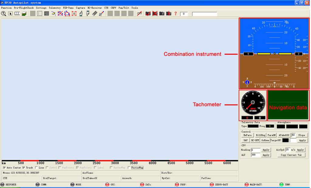
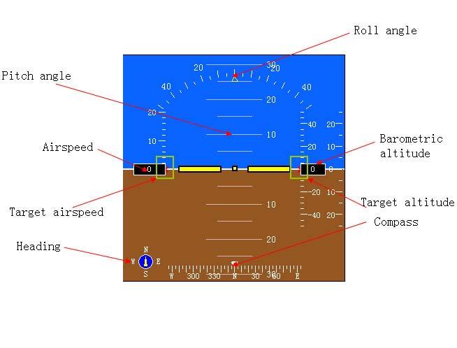
35 Combined Instrument
36 Time Zone Control Area It shows the GPS time in the internal autopilot. Control area includes general control and CPV control. General control is used to operate the parachute, engine shutdown, the receiver switches, UAV ~ CPV control mode switch, and change the target destinations, start gliding, automatic take-off. When you press the emergency parachute, the aircraft immediately stop the implementation of actions and automatically open the parachute in the delay of 3 seconds. In case of the aircraft may shutdown its engine in flight, you can immediately press the start of gliding, the mode of the elevator controlling height will be changed the mode of the elevator controlling airspeed, so as to control the aircraft to glide down at a set low speed. The mode will not be canceled until the autopilot is repower on. When entering the control mode of CPV, CPV control can set the target flight height (meters), speed (m / s), and heading. Pressing copy button can copy the current flight altitude, flight speed, heading to the data box. Settings Dialog Box Selecting the "Settings" in the menu the Settings Dialog Box will appear, the following are the introductions to the settings operation in Settings Dialog Box. In addition to special instructions, as soon as the settings are uploaded to the autopilot, the setting are kept by the autopilot. Even the autopilot is turned off, it will keep the last setting. Serial Settings

37 In order to establish the communication with the autopilot, you must properly set the serial interface. If the autopilot is turned on, and the ground station has entered the monitoring mode, but the communication light on ground station is gray, that means the serial interface s settings is not correct. You have to correct the settings, If communication light is red and flashing, that means the settings is correct, but the baud rate is not correct, you must try to change the baud rate until the communication light turns green. The default configuration of radio baud rate of UP30 is 1200, the internal communication baud rate of ground station software is 1200, when it is opened. Every time the UP30 pilot is power on, its default configuration is This ensures that UP30 can communicate through direct cable connection or a wireless radio connection as it is turned on. In the case of connecting the computer with direct cable, you can modify the baud rate for , and then the baud rates of ground station software and the autopilot are changed temporarily to be , after that, high-speed communication can be carried on. You also can view the data of sensors and data of altitude with the frequency of 30Hz, and download the data of photography. If the UP30 is supplied with bps radio, the default configuration of autopilot is bps after it is turned on, and the default configuration of ground station software is bps. If you want to change the autopilot s communication

38 baud rate, you can set a new baud rate under the normal data communication. At this time the autopilot will be changed to use the new communication baud rate, and ground station software will also be changed to use the new communications baud rate. If you have the automatic tracking antenna which matching with UP30, you should set corresponding communication serial and tick "Antenna Control Enable". If the program is running, and the ground station software founds no corresponding serial it will automatically close the antenna control. Altimeter The ground station software have to enter its monitoring function before carrying on the relevant operations of the autopilot, if it does not carry on data playback. You firstly carry on the program, select Monitoring < Function in the menu or press F2, then the ground station software will enter the communication mode with the autopilot. Then the program will open the serial to communicate with the autopilot. After ticked start the automatic monitoring, the software will enter the monitoring status directly. There are two input methods on setting ground level. 1 When setting the relative height above the take-off point as the target height and before the plane is taking off, you

39 should set the ground level of take-off point to be zero, and the flying height in the routes table is the relative height above the take-off point. 2 When setting the altitude as the target height and before the plane is taking off, you should set the ground level of take-off point according to its altitude in GPS positioning, and the flying height in the routes table is its altitude. The settings in Take-off Checkup Dialog Box is exactly same with the settings here. Note: When the download data is set to be telemetry data, the autopilot will response received for three times to confirm that these settings are successfully set. If the autopilot does not response, please set again. Pitot Block the pitot (do not hold down), and do not let the airflow directly enter into the pitot, click " reset" to clear the pitot. The clearing in Take-off Chekup Dialog Box is same with it. In order to get the exact airspeed, you need to set airspeed coefficient. Clicking "Obtain" you can get the current coefficient of the autopilot (the original coefficient). If the pitot is accidentally set to be other values, you can

40 click "default" to obtain the default parameters, then click "Apply." When the measured airspeed and the actual airspeed has a great difference, the correct coefficient can be obtained by the following calculation Flying on a no wind day, by comparing the air speed and GPS ground speed through flying data, you use the following formula to recalculate and modify the sensor s coefficient. New coefficient = (ground speed / airspeed) ^ 2 the original coefficient Fill the new coefficient in the box,, then click "Apply", the autopilot will response " received" for three times, that means the setting is successful. Servo s Settings RC channel 6 control is to choose the object which is controlled by the 6 th channel of remote controller. After chosen, the autopilot will response received for successful settings. Every time the software is running, it is set to control CH6 automatically, but in the internal autopilot it is set to control the last setting control channel. If CH6 of remote controller is set to control the parachute. You shall control the parachute servo to the opening position by using the remote controller, and then press On Pos, the autopilot will record this position as the parachute opening position. Similarly you can control the parachute servo to the closing position by using the remote
41 controller, and then press Off Pos, the autopilot will record this position as the parachute closing position. As soon as finishing settings, you shall turn off the remote controller, and click Test to check whether the above settings are exactly executed. If CH6 of remote controller is set to control the two mission servos, you can set two positions to them in the same way with Parachute Control. And you can set the waypoint data to control the mission servos, when the aircraft arrives the waypoint, it will automatically control the servos to the setting positions. When the camera settings set to use the rudder as shutter control, the task of steering control of the camera shutter 2, a steering gear. At this point "position 0" position after the shutter release, "Location 1" location for the pre-press the shutter, "press the shutter position" as the shutter button in the end position. See the photo section. Check the box to set the cross-linked set of special control of the layout of the flight control of aircraft in selected, press the Settings button to set the control mode. "Get" button to get the current flight control of cross-linked control mode. Actuator configuration under various modes see airborne part of the flight control system steering instructions. In 1,2-channel mixing, the prohibition V tail and flaperons mixing; in non-channel mixing 1,2, you can select the V tail and ailerons mixing lapel. When you select a cross-linked control, if the implementation of the two steering the opposite direction (for example: V after the end of mixing, playing remote control elevator, 2 rudder servos actually become the rudder movement, but actually became a hit rudder lifting action), then you need to "get" set up within the flight control situation, and then later in the corresponding term "exchange" option to make the opposite choice, once again "set" to the flight control, the rudder will be able to function normally. Note: The cross-linking and exchange setting is also passed to the flight control, so in the press "set" before all the settings to be correct. The current round is not with the rudder through the Y-cable connections, and requires a separate channel of a steering gear; or the front wheel and rudder movement in the opposite direction because of, not by Y-cable connection: drop-down box to select the front wheels through the linkage channel, press Under the "Settings" will set the corresponding channel and remote control rudder rocker
42 linkage. If you need to reverse the direction of the front wheel action, see the corresponding reverse channel settings. Transmitter 1 channel remote control to select a channel selection means to control rudder, aileron and rudder if the aircraft is in accordance with the manipulator used to select 1 channel remote control rudder; if the aircraft only, select a channel control aileron Vice wing; the rudder if the aircraft only, select a channel control the rudder. Drop-down box to set the receiver to use the receiver type of the current (factory default setting autopilot internal receiver for the Futaba PCM1024). Each run the software are shown as PCM1024, the autopilot for the last time within the set type. When using the Futaba 2.4G receiver, select the appropriate option, then press "Settings" button. Some special versions of the autopilot does not require the receiver, the receiver can select no options. Downlink data can be set to "steering data", so you can observe the dynamic servo control the situation and tasks mixed steering gear, steering the work of the position of the umbrella. Note: The location must be set correctly after the parachute, the parachute all the action in order to run correctly. Must be properly set after the type used to plug in the receiver or to the steering gear power steering gear. Otherwise, the wrong type of receiver will output the wrong amount of steering gear, causing damage to the steering gear steering gear overtravel movement. pitch roll angle

43 When installed inside the aircraft flight control, the roll bias by setting the pitch to make the flight control of the pitch angle and roll angle correspond with the aircraft attitude. Place the aircraft wings level, press the "Settings ", the pitch flight control roll angle will be cleared. Press the "access" can be factory calibrated zero flight control and the current value of the offset value. Press the "clear bias" flight control will revert to factory settings attitude situation. tachometer When using the speed sensor is the actual speed obtained

44 Security Settings by doubling the speed, select the correct frequency than the speed display. This setting is not uploaded to the autopilot. Set the contents of the alarm box to set ground station software alarm conditions. If there is no speed sensor, select the No Stopping alarm sound alarm to avoid excess; when using a single engine, select the single parking alarm, speed sensor and insert RPM0 interface; when using the twin-engine aircraft or airship, select double parking alarm, then no matter what engine will stop the alarm. According to the flight control and steering gear to use different batteries, can set the voltage corresponding to the alarm range. Speed data is not transmitted in all cases. In the "telemetry data" mode and "PID data" contains speed information. GPS lost star treatment will be set in-flight loss of GPS positioning data is processed. GPS lost stars, the flight speed and altitude will remain unchanged, you can choose to continue forward or place non-stop circling waiting to be processed. In positioning restored, will continue the original flight mode. Place at this time is just hovering turn rate to maintain a certain grade or turning circle, will be flying by the winds spiral track. Automatic parachute protection could automatically in the event of an emergency parachute protect the aircraft and equipment. Height from the ground set up automatic parachute ripcord protection, the plane took off from the
45 height above the ground. Once the parachute protection to meet the conditions, the autopilot will first issue a stop command, the delay set "parking parachute interval" issued after the parachute instructions. "Parking parachute interval setting" minimum set to 0 seconds, the parachute while parking, the maximum can be set to 255 seconds. Parking protection settings in the engine stopping the implementation of the protection action cases. This protection can be set to automatically start the glide (glide airspeed can be customized), and automatic home (along the feature to automatically turn off all direct returns 1 point). A prerequisite for the implementation of this protection is necessary airspeed greater than 9m / s while in UAV mode, stopping to detect the speed measured by speed sensor prevail. Once the start gliding, you must autopilot off from the new power will be lifted. More than once to meet the airspeed 9m / s and also in the UAV model, this condition will fail to meet the airspeed. So do your fingers blocking the airspeed on the ground pipe inspection, must be checked in non-uav mode. Note: parachute protection box with a few settings are transmitted to the flight control, so be aware of when each set of the settings are correct. Once the transfer to the flight control set and confirmed, the flight control will store these settings, even the next boot is still valid. When checked, "must meet the airspeed starts", the autopilot has been monitoring from power the current airspeed, once the airspeed over 9m / s and is in UAV mode, starts above the "high" and "diving" Automatic parachute protection. This condition is automatically protected by the above two prerequisites. This avoids cutting UAV model on the ground, because the aircraft relative to ground level to 0, to meet below the set height, will be automatically parachute. If you do not check this condition, as long as the above "high" or "subduction" one of two conditions will perform parking parachute action. It should be noted: on the ground airspeed tube blocking test when the finger, remember not to test the UAV model, which will satisfy the airspeed over 9m / s condition, this condition will be ignored autopilot directly determine the other protected conditions. "Below the height of parachute" can be set once the aircraft is lower than the set height from the ground (and for

46 the UAV to meet current mode control mode), for any reason will be the implementation of parking parachute action. Therefore, the use of this condition, be sure to pay attention to remote controlled switching of the high altitude and route points, must not be lower than this setting. "After a continuous dive automatic parachute for 3 seconds" check, the aircraft is as long as the UAV model, and the decline rate of the aircraft altitude dive 21m / s, for 3 seconds, will perform parking parachute protection. The implementation of automatic parachute protection action is: Once the parachute to reach the above conditions, immediately stop the flight control (including closing dampers and relays parking), in stopping the implementation of "stop parachute interval" seconds after the parachute opens automatically. camera version UP30 aerial camera with automatic control functions. See the specific camera settings and features section


47 Flight control and flight control software version of the hardware serial number has been set at the factory and can not be changed. Only in the repair, maintenance and upgrades need to know the version information. automatic take-off UP30 autopilot have various forms of automatic take-off and support: roll, hand throwing, catapult, car off. Must use the parameters listed in the roll from the ground speed, climb a high end, roll failure time, angle of attack from the ground. Close the remote control or the remote control remote controlled switch (5 channels) choose to UAV mode, press
; vehicle acceleration plane (car off mode).")
48 the control box to "auto off" button, the control mode will appear as "speed" mode, you can release the aircraft aligned runway (roll off mode); Throw aircraft (Throw off mode); launch aircraft (ejection mode); vehicle acceleration plane (car off mode). Accelerating state, the aircraft will maintain control of the rudder and the front wheel does not turn the aircraft roll, aileron and elevator neutral capture the output value of the maximum throttle setting automatically throttle value. In accelerating the set of "roll off the ground speed", the aircraft angle of the plane to the control lever to set the "angle of attack from the ground" and keep the aircraft climbing over the set until the "end of a high degree of climbing." The process control mode will appear as "climb" state. In this process, the aircraft ailerons to maintain level flight, the aircraft did not turn the rudder to maintain the throttle still set maximum. If more than set the "failure time roll" the aircraft has not reached the takeoff speed, the autopilot will stop the engine, the end of the roll. If you want to fail this feature, set the time set for the larger 255 seconds. When the plane reached an altitude of a high end set to climb after the autopilot for the UAV flight mode automatically converted route flight mode. automatic landing Automatic landing using UP30 must correctly set the parameters for this page

49 Automatic landing system can choose to disable the automatic landing, automatic parachute landing or landing roll automatically. Set to land in the way here, if the route is checked, the landing point of a point, the aircraft flying this route UAV mode point, according to the selected landing approach landing. If the parachute, then enter the waypoint arrival radius, will perform the stop, delay 3 seconds parachute action; if it is downhill, the aircraft will automatically fly to set the course for the landing roll landing. installation settings Autopilot installed, to the ground station software, select the menu "Settings -> Install Settings", select the autopilot as shown in Figure axis and the corresponding relationship between the body axis. After 3-axis right choice, there will install the code, then press "Settings." Autopilot must be re-power to make the settings take effect. interface configuration

50 Photo According to their own needs can be used to set the line with their instrument display. UP30 aerial camera with automatic control functions. Camera has two modes: 1, such as the time interval photographs. 2, equidistant intervals photographs. 3, fixed camera Other time intervals can be set between 1 ~ 255 seconds, equidistant intervals can be set between 1 to 65,535 meters. When you select the fixed camera mode, press the "Settings" will be converted to fixed-point camera mode camera mode (even if the power off autopilot and then the new power, remained the last set of photo mode). Press the "Import point data" button will pop up file selection dialog box, select the point you are ahead of schedule to complete the exposure files compiled until the import progress bar shows 100%, and the autopilot response "has been received." The best time to import the data using fixed-point direct serial cable connection with the autopilot and set the baud rate to , to ensure fast and accurate data into fixed-point exposure. In the choice of fixed-point data into fixed camera mode is completed, the prompts must be given after the autopilot off power to the new flight

51 Fixed-point data files using text file format, can will file save for. TXT, specific format is as follows: , , Among them the first act generally photographed point number from the second line up, by taking pictures for each sequence point of longitude, comma pictures, latitude, until finally a photographed some data Fixed-point pictures of location data must be located on the flight line designed. When auto-driving meter plus electric pictures, if after mode for fixed-point mode, will automatically extracted first photographed o 'clock position data, and constantly judgment plane with the current position of the distance, when photographed point will reach a certain conditions this distance automatic control cameras photographed. Because GPS is 4Hz update rate, so real shoot dots and default points may exist certain deviation, this and the flight speed has relations. But the real instrument zijia will be photographed point data recorded and replace the original default photographed points, and the pictures of POS data can be downloaded point, see behind. In choosing designated photographed mode import fixed-point data completed, after new plus electric
52 pictures do not carry out any manual testing, all shipping point don't checked a camera Photos can use electronic shutter control (relay control) or use the steering gear to control the camera shutter. Enabling steering gear control shutter, task 2 steering gear will become control the camera's steering gear. Steering gear adopt 3 gear control, specific Settings see steering gear Settings section. Action process gets for: the shutter 1 seconds later, pressing the shutter button exactly.5 seconds, and then release the shutter to release position. When using electronic shutter, shutter relay suck close after 1 second release. If need to change the time, gain more fits the absorption of time intervals, short photos please contact manufacturer change procedures. Start photography has two ways, one is the tasks window, click "start photography" (or press the start on the toolbar for photography ) The flight control will be in accordance with the above set photographic manner and automatic control cameras photographed. Intervals 2 it is checked the aerospace camera function point mission. Once the plane arrived aerospace point, if the target is a camera Settings 34 destinations will be started taking pictures Stop taking photos also have two ways, if the current camera is in a continuous interval photographic pattern, the manual press tasks window "(the" stop taking photos or press the toolbar for photographing stop ),Will stop taking photos action. This pattern is artificially start-up or both for the aerospace camera are effective starting point. But if encounter a photographic function of 34 destinations, it will start automatically again to take pictures. If reach target shipping points not photographic function, and this is the photographic state, will automatically stop taking photos. If you don't want to use a continuous interval photographic pattern, can control tasks window button to the "picture photography (or press the manual camera button on the toolbar. ) According to the next flight control receiving orders, and will automatically be photographic again. During the flight, can be used at any time Button

53 inquires the current photo quantity, as long as the plane after leaving new start counting off. Note: the number refers to the pictures here is in after flight control boot by camera flight control control according to quantity, not in the number of actual camera photo (because in before flight control control within may already have photo camera. The flight control in control photography will also record while taking pictures of longitude and latitude and altitude plane such information. By using non-volatile storage, so even if fall after power is still maintained, unless in the download and restarting and control before photography. When the flight control control after startup, in accordance with the order of the data from the camera began covering the position before 1 data. In flight or flight can be downloaded photos after the location data (suggested in flight after landing, use direct serial cable connection and set baud rate for , ensure fast and accurate finish data download). use Can download the location data, flight control button will require input need to download starting photos positions, as shown in figure: Have two options: one is, input zero will automatically download from 1 to the number of flight control all the photos location data. This operation must be in after flight control control, no pictures off situations (only this kind of circumstance of flight control system to record a current photo quantity); 2 it is greater than 1, enter a number represents less than 10,000 photos of need download starting positions. After the confirmation will be required to input end position, as shown in figure:
54 Fill in the input box automatically entered the starting position just now, when direct press enter will only download specified by the picture of the location data. If the input than the starting position number, will download designated photo data. Download pictures appending data stored in the installation directory "photos. TXT", the data in the data format preserved for serial number, time, longitude, latitude and altitude, elevation Angle and roll Angle, GPS heading Angle. Before you take photos in every flight copy and empty's former location data. UP30 auto-driving instrument for internal's largest photo data storage 2978 zhang, more than the amount of data will cover in front of the data. Another photographic open terminal can also be used to other switch quantity control, such as artificial precipitation of the flame homework ignition Because in implementing photographed drive instrument will record the movements in sync information such as the latitude and longitude of GPS positioning, so must be carried out after pictures action

55 PTZ control Servo 7 and 8 is a multi-function steering servo port. When using the PTZ function, corresponding to the roll control servo actuator 7, 8 correspond to the pitch control servo steering gear, steering gear, steering gear 9 correspond to heading control. After booting the default flight control PTZ control mode is manual mode. At this point, PTZ control to ensure that the case of the active window, press the control key WS AD or head servo control action, respectively. The top of the scroll bar displays the current value of servo position. About the value of the scroll bar representing the minimum and maximum actuator stroke. Scroll through the mouse to observe the servo travel, when travel reached a limit, double-click the corresponding numerical display boxes will limit the current servo position value is set to the display box (servo travel values between 950 to 2050). Step value is set to press the keyboard corresponding to the step that controls the speed of head rotation servo. ZC by controlling the two-letter keyboard keys can be controlled in manual mode, turn the steering head of the
56 course, when the axis of rotation to the same camera body, press the zero steering position can be set relative to the camera after each reboot body of the course, and when in the automatic control of course zero. Course steering transmission ratio can be set from the helm to the actual camera output proportional relationship between the rotation angle. For example: 30 degrees rudder head rotates 10 degrees rotation, the gear ratio is 3. Partial repair can set the maximum angle of deviation from the aircraft nose pointing to the default maximum angle between the flight line. For example: 20 degrees, the aircraft nose pointing to the positive and negative deviation from the default route will be executed within 20 degrees of partial repair action, if more than 20 degrees, 20 degrees to keep the amount of partial repair. This feature requires purchase of supporting electronic compass accessories. Setting controlled automatically roll pan tilt control method: First set installed, the aircraft autopilot level consistent with the autopilot (see above); Roll the aircraft onto the pitch angle of the position are 0; Manually adjust the steering head to head level (or need a neutral position), then press the "controlled steering gear zero" button, this action sets the head level or neutral position corresponding to the amount of steering control; The aircraft pitch and roll are also placed in a position likely to use the limit point of view (eg, pitch angle is 20 degrees, this value determines when the automatic control head, the maximum amount of pitch correction is 20 degrees, more than will be continued the maximum amount of steering correction); Again manually adjust the steering head to head level (or need a neutral position), then press the "limits of self-control servo" button, this action sets the limits of automatic control head position servo control of the maximum amount, while autopilot automatically calculate the angle of head movement and proportional relationship between the direction and control; Press the "automatic control" option into the automatic control mode. If you have electronic compass, the heading Revised partial function also started


57 Capture operation Into automatic control mode, set the target pitch angle head roll angle of Automatic Control. For example: both to 0, this time corresponds to the level of ortho-mode or set the neutral position. ADWS can be controlled using the keyboard corresponding to the target angle, step length can be set to press a button corresponding to each of the angle variation Capture menu is to capture the remote control flight

58 control operation values Open the remote, switch to remote control mode (RC). Control air inlet (3 channels) to need set position, press the menu options, capturing value. Please refer to determine the value of airborne flight control system "parking position" and "draft Settings" chapters content. Neutral value is plane to cruising speed, remote control loose stem flat flight all the rudder when flying CH1 ~ CH4) (surface flight control components, the control values recorded and as self-control flight neutral values. In the first flight and the plane has a big fluctuant circumstance, reset the neutral values. Specific operation: remote after take-off, achieve certain safety height, adjust 1 ~ 4 channel remote quantity to the desired cruising speed, basic can let go straight flight (can consult downlink flight data and track is sure), right now, the ground operation personnel press capture neutral value menu, flight control answer "has received". In press capture menu, remote need to keep the joystick motionless. Downlink data Download data menu can set download data types type In the table below describe various data type downlink data content and downlink frequency. Downlink data box will also display the current downlink the type of data and frequency. frequency frequency content comments high-speedradio Low-speed radio
59 Telemetry data 1 1 Flight data and flight control state diagnosis data The model for the most common mode Steering gear data (voltage, temperature), as well as the first four flight control servo data ~ 10 channel steering gear data Press show steering gear data dialog box GPSdata 4 invalid Display GPS data, navigation target. If already positioning, press will display the current GPS data Sensor data 15or90 1 Can download calculated value and voltage two ways and voltage value is mainly used for Press appeared after sensor data box. In selecting the actual value or voltage values calibration sensor way Neutral position 15 1 Download the flight control record position, only for steering gear neutral under three times Press appeared after steering gear, do not pass data boxes next using servo data after will pass under the return original

60 report data model PIDdata 15 1 Downlink in PID adjustment is Adjustment of the PID description steeringgeardialogbox necessary data. Speed is invalid. Downlink navigation PID When using direct line of 15Hz UP30, even while the downlink frequency 30Hz are obsolete. The default is 1 seconds after startup remote sensing data 1 times, when check other types of data, must switch back to downlink telemetry data state. Scroll bars and data frame shows the steering gear channel current data, the little box showed in the steering gear channel is set reverse. Press behind the "reverse" button corresponding to the channel steering gear reverse control GPSData frame

 and voltage values (the original value), through the")
61 Sensordataframe Display content as shown in the diagram. GPS data per second under four times will pass, can dynamically monitor GPS work. Without this data type low-speed radio next preaching. Sensor data download content into the actual value (calculation value) and voltage values (the original value), through the corresponding button downlink sensor data. When using direct cable connection, can modify communications baud rate for , right now can download 30Hz actual value data or 90Hz voltage data
62 Before taking off could observe the actual value, determine the gyro zero right. In aircraft immobile circumstance, gyro X, Y, Z's actual value around the zero to beat. The flat in aircraft basic situation, the acceleration of the actual value of X, Y, Z near in 0 the value in the acceleration around - 1. Voltage value used to calibrate the accelerometer and gyroscope, general by manufacturer with calibration, only in the output gyro zero is not correct, to keep the motionless, press "zero" button, flight control will respond in a few seconds after receiving ", said "has complete calibration, and see whether the actual value in gyro to near zero. If because the flight control voltage is too low or other factors lead to sensor parameters can be lost or confound, the sensor manual input the correct parameters value, then click on the "Settings". The correct zero parameters are 2.5 or so, the acceleration in proportion coefficients, the proportion of gyro about 3.0 in 200. Roughly coefficient 1 Installation of magnetic compasses in UP30 after installation calibration on the plane. Must have completed all equipment installation, can achieve the flight status calibration after work. Calibration procedure is as follows: 2 use cable directly connected and change baud rate for Downlink sensor voltage values, magnetic X and magnetic Y will show a magnetic sensor data 4 Press the "start calibration" slowly, after the rotation of the level of uniform plane 5 In turn over 1 lap above, click "finish", the calibration Xsf, behind Xoff Ysf, Yoff will appear calibration data, Press the "set calibration parameter" magnetic, calibration data is set to drive instrument inside, auto-driving instrument to plus electric power. Magnetic compass measured magnetic north, and true is the north has a certain deviation. GPS navigation won north is the geographic north say true north. True north and the Angle between the called magnetic north CiPianJiao. Different parts of the CiPianJiao is different, so by querying data after local CiPianJiao gain flying in this page, CiPianJiao, and "setting input CiPianJiao", in order to make auto-driving apparatus was obtained with the true north PianJiao. Set CiPianJiao will immediately after effects, no need to add electricity. Input formats for degrees, for
63 example: west slant six degrees 30 points, the input 6.5 degrees. The calibration parameter can obtain sensor, but unless necessary circumstances, do not set sensor parameters. Wrong parameters will lead to cannot normal controls flight neutral position Don't in the output under the condition of steering gear data transmission neutral position, because of neutral position under 3 times, and only after he preached will return to the output original downlink data type (steering gear data), because all using the same dialog box, so I cannot get the correct neutral location value. Other data type Other data type most only temporary downlink after several attempts, then back to the original downlink data types. Specific current downlink data type, can be in downlink data box displays. PIDchannel Select "PID adjustment" menu v PID adjust the window

64 Choose curve box "channel" drop-down box on the right, will send commands to fly under control, and preach PID data types. No matter which to choose channel, will send downlink PID data content, under which preach content is the same, the difference is that data to choose curve box the target and the current value of channel to paint curve. Red curve represents target, represent the current value of green curve. By choosing to scroll or not can control the dynamic display of the curve. When rolling stops, can use lower arrows control shows curve segment page. Use the mouse to click on a curve in the box from the upper left lower down into smaller makes pulling, y-coordinate will; From the upper left lower down to pulling, will get big. Makes y-coordinate Holding right mouse button can control shift curve, the mouse wheel can move curve among. UP30 System were nine PID control algorithm, including circuit.and the flight control loop and outer ring navigation control circuit. The control mode airspeed and height there are two:
65 Mode 1: (in flight control communication with normal, first checked > accelerator option airspeed - and then remove the ticker) - > the pitch (airspeed allowable value) + turn compensation (TP) - > lift steering gear; - > draft steering gear heigh Mode 2: (in flight control communication with normal, checked > accelerator option) airspeed - Airspeed + height compensation (VP) - > draft steering gear; Highly - > the pitch (limit value) + turn compensation (TP) - > lift steering gear; Use the mode 2 can make high control precision, up and down smoothly, is usually choose control mode. But this kind of mode is certain problem, when the engine after parking accidentally, the plane fall after lever will forward height is more and more big lead to stall. Use the mode 1 can avoid this stall phenomenon, but mode 1 height precision control ability is a bit poor than mode 2. So UP30 design automatic switching function, normal flight when used mode 2 controls flight, when observed engine after parking must press interface "start glide flight control airspeed" button, will instantly switch to mode 1, and maintain airspeed, minimum set. The purpose of decline Angle In flight, as PID adjustment according to the first mode 1 airspeed channel, then adjust the corresponding adjustment mode 2 airspeed channel PID values The flight control internal factory default setting is, but airspeed control throttle mode of "dialog - > throttle airspeed flight control" option does not reflect internal Settings, just as the need for setting checked or remove the ticker, already receiving flight control will response Twist with navigation mode also have 2 kinds: Mode 1: (aileron channel, the rest outside except D item fill parameters 0) Navigation * BP % + correction - > > direction -- turning rate of steering gear Mode 2: (main control mode, turn channel could be used except D item, the rest outside fill damping 0) Navigation * BP % + correction - > > aileron channel - aileron servo pull Each PID circuit are a below enable options, in front of the box in the "ON" or "OFF" marks the channel is working (note: must downlink PID data can display correct state
66 Each session, will automatically open all channels). If pitch, turn, aileron, highly channel to any one is OFF, the channel state when the steering gear in automatic control corresponding output fixed record neutral rudder bits. Click "gain parameters" will get all the PID parameters, click "send parameters" will send all the PID parameters values. If you want to change one alone, please first parameter value, then get parameters change requires changing parameters alone, finally send parameters, otherwise it might lead to other parameters change. Click "save parameters" can present PID data save to file; Click on the "open parameters" can open a has been preserved PID parameters group Copy the current values "button will the current state of the plane value is copied to the corresponding neutral value box. When flying in PID debugging, usually closed some channels, open some channels. When in remote control when flying RC interference or remote control failure or fly out remote distance, would fly control will automatically switch to UAV mode, if some channels are not open, the plane will not normal UAV airline flight and cause accidents. Once the switch to the UAV mode, press the "open all channels" button to immediately opened all PID channel, the default PID numerical can basic guarantee the safety of aircraft flying pitch channel (inner loop, 30Hz) The pitch channel through the elevator to eliminate set with the current pitch pitch difference. Adjust alone must be closed pitch channel, the outer ring of its altitude channel speed channel or channels. Can also close to exclude turning compensation because the impact of turning. Through setting goals Angle (RPV value in target below, send), to observe with the current set of pitch changes pitch curve. From curve changes to the gain parameters decided to amend the PID value. When the RC remote level flight, observation plane flew Angle (the shekel of the missing on scale should be on the ground, or need to rethink the calibration of flight control rolling corner bias) pitch. The plane flew Angle of the flat fill Angle of the neutral value, then box set maximum and minimum permitted self-control flight Angle. Three values are set according to the sender, let after setting. Remember
67 that these drive instrument If the plane state change greatly, reset the. Airplane autopilot in the pitch Angle are set maximum and minimum range. If feel aircraft dropped during the height of automatic falling faster, can set a small slide Angle. If the plane is the surplus power, can set the biggest climb smaller Angle To test the inner control effect, can the channel in setting target and close the outer ring channels from RC model, after switching to RPV mode. Now each make can loop and began to work. In addition to the pitch channel RPV value set the target directly outside, turn channel, highly channel, speed channel RPV value is a set of value, the target is thus RPV mode with the benchmark joystick deviation neutral rudder bits produces offset value. For example: setting value neutrality turning channel 5 degrees/sec, if cuts RPV mode, 1 channel, the joystick in neutral position at turning the target aircraft is 5 degrees/seconds; If the joystick deflection produce - 10 degrees/sec, the plane at turning the target is - 5 degrees/sec. Generally, cut in debugging RPV mode will no longer move any rocker. See flight control mode RPV section! Turn channels (inner loop, 30Hz) Turning to reach a set channel control rudder Angle rate. Separate debugging when need closed its outer ring channel navigation channel Fruit used this passage, then must turn control failure aileron channel, namely aileron channel PID parameters should set to 0. Also can install PI for 0, proper parameters D will increase cornering roll damper. Maximum can set maximum turning rate or turn slope. RPV value while turning rate and set the target, turning slope when using rudder cornering, the corresponding unit is turning rate degrees/seconds; When using aileron cornering, the corresponding unit is slope degrees Aileron channels (inner loop, 30Hz) Aileron channel control to set until roll slope, and thus for the turn control. Separate debugging when need closed its
68 outer ring channel navigation channel. Its target and RPV value only the target directly turning channel RPV value and set If you use this passage, then must turn control turning channel, namely failure rudder turning rate channel PID parameters should set to 0 Altitude channel Highly channel realize height difference elimination If use the mode 1 (1Hz), is highly channels directly control, setting up the right changes after a can eliminate VP speed and altitude coupling phenomenon If use the mode 2 (5Hz), is highly channel is the outer ring channel pitch channel, it outputs is the target pitch Angle Speed channel (30Hz) If use the mode 1 (5Hz), then the pitch channel airspeed channels are outer ring channel, through the output elevation Angle, control the pitch to eliminate velocity error. Here is the unit meters per second. If use the mode 1 (5Hz), then the pitch channel airspeed channels are outer ring channel, through the output elevation Angle, control the pitch to eliminate velocity error. Here is the unit meters per second. Navigation channel(4hz) Through the GPS estimates heading get with the current target heading course error, output turn rate or turn to inner slope, so as to eliminate channel course error purpose. Set the BP values can be involved in controlling function setting this channel the percentage. In choosing paint navigation channel curve flight control will take after 4Hz frequency output only with the flight data on navigation adjustment. Low-speed radio not output this data types Fixed channel(4hz) If make a crosswind fixed channel can enable points also and navigation along at a function, deviation from the crosswind caused by this channel course error correction. It is the Angle of adding to the course error output, then after navigation Angle of output of channel turn rate PID. Therefore, only the navigation channel in enabled, fixed channels only output, if only need fixed channels for work, and don't work, then heading channel can be set BP = 0. In the menu along control, if have closed, will make all

69 Map operation along the shipping points along function failure. UP30 map interface provides customers with very convenient visualizations, making mission editor, flying monitoring and revise task becomes very convenient. Operating toolbar layer control in figure interface Will appear as shown establish map If you have own electronic map data (Mapinfo format), click electronic map button, select your electronic map in the file (. GST documents), will use your electronic map a map background 1 If you want to use scanning map (grid map), please select layer the drop-down box behind for "map layer". Choose to open your map files, specified. General scanning map after the need for registration can use it. Registration method has two, one is manual write configuration files: 2 will need to use to save the map after a scan JPEG compression format, filename cannot use Chinese 3 run Windows the attached "notepad" program that will following content paste to notepad editor inside

; When the name input in")
70 The first of six lines behind File the double quotes for scanning map filename "nt. JPG" From line 8 began, the first, the second brackets is longitude and latitude brackets is corresponding pixel position (can use such as photoshop kind of software, check the corresponding pixel position). If not the last point, please keep the last comma; If it is the last point must be removed a comma (such as Pt 4 points). A scan map will need at least three match be punctual. The rest of the format and the above the same 4 select "notepad" menu "save", in the preservation of the popup dialog box select save type for all files (shown in red circle); When the name input in the filename, expand need to store called. TAB (shown in blue circle). Second Is the use of the menu "tools - > map configuration

71 Click "open pictures", choose a picture file (filename and paths cannot have Chinese). According to coordinate the format selection degrees, degrees points or degrees format, input coordinates our coordinates, and then in the picture, click generated in corresponding position reversible. Then enter new a coordinates, click the new points in the chart. At least three percentage points above click. Finally the save configuration, generating the corresponding configuration files. If you don't have any maps, or you need to customize iconic dot, line, face, please select the type of layer below marked layer. Then use the open, choose has generated mark layer files (any form of. TabMapinfo files). If using a new, please specify filename, if you want to copy is now in map region shows Open, the newly built, copy routes the operation with similar documents above. Maps from a variety of layers, its composition and relationship table, shown in the upper layer will block the following layer
72 Location Layer Content 1 Track layer Flight path shows the path layer 2 Airborne level Show download airborne flights. When the target format airline flight 3 Standard layer destinations are displayed when the corresponding standard route 4 Marker bed Layer display and edit the content of signs and markings 5 Scan maplayer Display the contents of scanning to layers 6 Electronic map layer Show Electronic Map mapdisplayoperation Auto Center If the aircraft flying out of the map display range, it will automatically change the map center to the current aircraft location. Track layer Control whether to display the flight path Routes Route design layer is formed by the destinations, was elected in the course, It will connect all the destinations in order to form routes. Marker bed Control whether to display the marker bed Route design layer Flight control design layer is displayed Airborne route layer Download the airborne route control whether to display the layers Scanning to layers Control whether to display the scanned map layer Electronic map layer Control whether to display the electronic map. More complicated in the electronic map, but also frequently change the size of the map display, pan, or set the

73 route, you can turn off the display, will accelerate the display speed Right menu Arrow Map tools from other states to switch back to the normal arrow. enlarge Current map tools to zoom in, click on the map, will be at the center click, zoom the map display. If you hold down the mouse and hold, pulled out a rectangular box, the contents of this rectangle to zoom into the map display area. Right-click to cancel this state Narrow Tool to narrow the current map, click on the map, click at the center will be to narrow the map display. If you hold down the mouse and hold, pulled out a rectangular box, the contents of this rectangle down to the map display area. Right-click to cancel this state. Translation Pan the current map tool. Hand-hold on the map and drag the map display area pan. Right to cancel state Center Tool for the current map center. Click the mouse on the map the map will be displayed at the center. Right to cancel state Choose Mobile Into the destinations selected state, hold down the Ctrl can be added to select, hold down the shift can be reduced election. In the single-point selection, if blocking the route selection, you can turn off the flight connection. Select a flag at the top destinations below the small triangle or rectangle can be selected destinations. Selected, hold down the destinations to connect directly to mobile destinations
74 Using the Toolbar of the map display, display ratio. To directly specify the center Distance measurement Using the Toolbar Into the current map tools to measure, from the point the mouse at the beginning, as calculated under the mouse point of the distance between adjacent points and the total distance (the distance at the show), until the continuous double-click the mouse, the end of time measurement. Marker bed Editor Marker bed can be customized some special points, lines, areas, etc. added to the map for navigation and mission to provide reference. Sign any change layer into the hard drive immediately, no save operation. Add logo Adding signs or open sign in the new layer after layer of editing tools to use logo Click 4 one of the tools, the map becomes the current tool to increase sign. Mark on the map where you need to add direct manipulation with the mouse can generate the corresponding symbol object. Right to cancel added state. Add a line when the mouse to click the first point from the beginning until the end of a double-point line to produce the final editing Select the logo Right-select the \u0026quot;select - Move\u0026quot; tool, then mouse click marks the object, the object appears as a small sign that the check mark box to handle, if you hold down Ctrl key, you can add more selected objects; If you hold down Shift key can be removed from the selection object object. Use Marquee tool to pull the mouse inside the box produced by all signs the same time objects and destinations selected to fill the indiscriminate combination of Ctrl point selection can be reduced with Shift select points. Note: Only the marker bed and route editing layer object is selected Mark mark Select a sign of individual objects have been added after the
75 right mouse button and choose "Mark" will pop up a dialog box that asks for tagging content. Add the label can also be selected and moved. Move flag Select one or more signs in, hold down the handle to the drag, you can move the selected object. delete flag Select one or more signs in the post, simply press the keyboard's Delete key to delete all the selected content. Route Route layer, including the route layer can be edited and downloaded on-board flight level. Edit object red route layer, said layer of airborne route in blue object. Two layers of data each corresponding to a list of destinations. Is the difference between two routes only edit the object layer can be selected and edited show only airborne route level route download, can not be edited, only deleted If you want to edit the airborne route can download routes, Then Edit route layer editing. Copied to the establish routes layer Or by opening new routes to obtain an editable layer. If you already have a route map layer, the route will open with a new layer replaces the old route layer. Can be checked in the new copy when the contents of the old route layer. Can also create a new layer, copy the content layer from the download route. Can be used to save the route flight control content downloaded to the ground station software. In use Upload the entire route, the flight control will also answer "received" at the same time automatically download the data just received the route that routes received correctly. Increase destinations If it is generated from 1 point to start a new route, click Tools to map a growing current destinations. Under the
.")
76 first point from the point of beginning, until the last point double-click the mouse (press the Esc key to cancel the half-way destinations editor), will automatically generate a series of destinations in sequence. In addition to new destinations generated different longitude and latitude, and the remaining value of the same template (see edit waypoints). Destinations in the production process, the distance information will show the current segment distance and total distance. Be careful not to over 100 destinations Click the mouse again, automatically generated from the last point has been started, generating a continuous increase in flights. If you want to destinations in between the two into a series of destinations, first with the "choice - move " command to insert the first point selected, as shown in the 2 points. Then right click and select "Insert Waypoint", then the map tools to increase destinations into its operation as described above, except that the resulting flight point into the original 2 points and 3 points between Select destinations Selected waypoint symbol selection operation and the operation of exactly the same, select the symbol see Tip: Select flight in a single point, the interference by the red route chosen is not easy, first remove the route displayed. To do click on the map below the "route " check box. edit waypoints Destinations, once produced, will generate the corresponding data table destinations. Click the route point data table (pictured) Will open

77 Destinations in the corresponding data table of the data destinations. Can be entered manually with the mouse to select and modify the waypoint latitude and longitude, altitude, speed, reach the radius, standard style, and standard time. Press Enter to confirm entry to modify. Directly modify the options for the hook. If you modify the latitude and longitude waypoints are waypoints on the map, press Enter immediately after the change to a new location. Photography and see the work of the task of automatic steering Settings dialog box corresponding content. When the ramp function selected to represent the target destinations and points of the slopes in the previous flight model aircraft. When the camera is selected, a representative when the aircraft reaches this point in a row picture. Templates are used to increase the flight point with the mouse the default value. Waypoints can be generated to modify the template before, the new generation of different destinations in addition to latitude and longitude, the other with the same template. Tip: Double-click the serial number box the number directly, immediately becomes the center of the map of the destinations. This did not know the exact location of destinations to provide easy to find. Select Edit on the map a single waypoint, right-click and select menu "Edit Waypoint"will set sail point data transfer form, the difference is the choice of destinations in the first position in the table. For the selected single or multiple destinations, using the context menu select "Select - Mobile"feature, to seize the handles directly on the map in the desired position to move and release the mouse, you can modify the route intuitive drag position
78 Tip: If you want to manually add and enter the known latitude and longitude waypoints, can be increased using the mouse on the map waypoint, then modify the waypoints using the data table is known data points. Double-click the point of latitude and longitude of the aircraft below the map will pop up a dialog box, you can direct the aircraft to set the current latitude and longitude points to an already existing destinations delete destinations For selected destinations, press the Delete key to directly delete the selected waypoint, the rest of the new destinations will be automatically sorted, followed by the serial number of the remaining big move closer to the small number. Upload waypoints Even in flight destinations can also be uploaded in real time. There are two ways to upload destinations: Single point upload This model is suitable for certain destinations only change the data, and did not delete and add destinations, the total number of destinations remain unchanged. Destinations need to upload the radio, right-select the "Upload destinations", the software prompts: "sure you want to upload X point data?", select OK, the point data will be uploaded to the flight control, flight control response immediately "Received", and automatically download the data confirm the destinations. All Upload If you edit the layer routes the total number of destinations destinations airborne route the total number of layers is inconsistent, that is, add and remove destinations operation, this time all the destinations need to upload all. After uploading, flight control response "Received" upload time depends on the number of destinations. If you want to upload 100 waypoints, you may need to receive a response after 20 seconds, and immediately all the destinations automatically download the data. In the meantime, please do not send any other commands. Low-speed radio will not automatically return waypoint data, only the response has been received. Download shipping point
 or full download (0) Tip: Click on the route, will appear in the box, the")
79 Shipping point data download have two kinds of cases, dot, routes in the uploading navigation data automatically download (after high-speed radio); Use Tools download shipping point. When using a download tools will remind is need single-point downlink (input need to download the boat some serial number) or full download (0) Tip: Click on the route, will appear in the box, the total route distance away. Automaticroutegeneration Layers in the new route on the map before take-off to generate a random waypoint, select the destinations; or open an already established route, select the waypoint to be inserted. Right mouse button select "Insert Auto route", the left mouse button in the corresponding position on the map to draw the first route (left after the starting point of the next hold and drag the mouse to the end of the first segment), will pop up a " Automatic Route Builder "dialog box (Figure). Automatically fill in the box under the start and end point of the latitude and longitude and the length of routes and route directions, you can manually modify the end point latitude and longitude, and then press the "Calculate route direction"

80 automatically calculate the route directions and route length. Can also manually modify the route directions and route length. Then enter the required interval and the flight routes Routes. The first route is to turn right after the default of 90 degrees, select the left after the first route will turn left 90 degrees. The real route for route calculation parameters are: the starting point coordinates, route directions, route length, route spacing and Routes. After setting, press the generated route, will be automatically generated aerial route. Same map can draw multi-block aerial route, simply has to choose the routes into and then right select "Insert Auto Route" button. The routes of all new generation to the other parameters are subject to the template settings, so you must first set the height, speed and other information and then generate new destinations. Formats routes In type routes are associated aerospace point additional custom circulation flight mode, click shown Pop-up window as Select "open" will open the existing edit good formats routes. Select "save" will edit formats routes since definition file deposit. Click on the "upload" will the current open or edit formats routes to the flight control, click "download" will fly accused of existing formats routes download and editing. Note:
81 whether to download or upload all seven kinds of patterns and transmission There are seven formats routes can customize, each pattern routes including eight navigation points. Plane has reached the target with formats routes after 1 - > along the 8 - > 1 serial number circulation flight, by the time of the flight time accepts the formats decision. Type in "time" column will show the rest of the formats flight time. When formats is equal to fly down a time target point Tip: to have the navigation point type flight set larger contains 1 ~ 8 o 'clock arrived, so that the radius of fly directly into the radius to after type 1 point, avoid must fly to arrive again type center type 1 point. Note: the flight between type points along the function, and has reached the radius of 34 destinations for setting arrival radius, when in the edit formats point between the two nearby formats points from must be greater than the radius value. Note: every time running the program automatically append when last open and save formats routes, the corresponding operation in flight format file format for additional have target point at the air routes in flight map shows the corresponding eight formats points. If the corresponding pattern route not current flight formats routes, please Note: if a shipping point chosen a pattern routes, the pattern of 8 air routes between the distance between the adjacent point point set must be greater than the fact, reach 34 destinations, and uploaded to drive apparatus type instrument zijia guaranteed relay route with display consistent. If the distance between 8 points are less than formats navigation o 'clock radius, will lead to deadly navigation dead circulation. When eight points of arbitrary format shipping the distance between two adjacent shipping point less than setting formats, drive to reach radius will call the default instrument 300 meters radius, and flight line type park station type routes by mistaken. Notice The height and speed type flying around the center formats in value shall prevail, while in flight, change type accepts the height and speed, and a separate upload the navigation points, the height and speed type flight also immediately change. For
82 instance can surround certain point for different high hovering; If you are going to change this pattern flight, aerospace point formats routes mode, or upload again the formats routes, it must be again for the current set of target shipping point, ability makes flying navigation some changes to take effect Choose a format routes for editing. The data in the data boxes are based on metres. Can directly in the picture and move a certain pattern choice in point, also can aerospace point X, Y data box directly modified distance navigation point type bias value and enter confirmation Navigation way and navigation logic navigation logic Must set the take-off point for 1 point (see shipping point edit operation), after startup target for 2 point, and then when you get to the target point downward, order a navigation point flight, when fly after 34 destinations outside all be automatic fly to first navigation point, and then have been around navigation point 1 do formats flight (so navigation point 1 must set a pattern routes, typically is a hovering around the top of head of course). If 1 point to zero, then type the time all planes were in shipping point back to 1, will continue to fly to 2 points, repeated 1 ~ last point of circulation flight Whatever the flight mode, as long as the flight control to meet the shipping point judgment (two conditions, behind introduction), the target will order folding. Even meet the conditions to other shipping points, with current flight control still target point for flight goals. Arrive at the target of steering gear and camera, task after according to set movement. During its flight, if the target function, the plane will have along along this point and its former bit of attachment flight; If the target function, the plane will with slope along this point and it a bit before the slope height difference formation flight. During its flight, can revise flight target. If altering the target and the current target point is different, the plane immediately flew toward modification target point; If altering the target and the current flight target the same format, and is in flight, then start over it.in formats flight. When modifying target, the plane will fly after all the air after the target until back to navigation point 1 point. If the target point is 1 point, and 1 set pattern time of greater than 0, the aircraft type route back to 1 and always formats flight, unless changed again target for other shipping points

83 If upload modified shipping point exactly target point is toward new goals points plane flew immediately; If during flights upload changed all navigation points, then plane flew toward target new position; If modified fly along the slope flight or one of two points, criterion with new two attachment and track the height of attachment to fly. If want to change is the height, speed type flight in aerospace, modify the center point of height and speed selection and single point after uploading the centre of 34 destinations If altering the target for 200 points in 34 destinations, the plane will immediately flew to taxiing landing point of access into taxiing landing mode If during flights to switch from UAV mode to other flight patterns, cut back again; pattern UAV Or in the UAV mode flight, switch targets navigation point: if the target function, they are first along almost vertical plane fly to route along its airline again next. In any case switch targets point to one point (aerospace) when and if the take-off point 1 point, so the plane will have along toward all the last bit of 34 destinations with 1 point of attachment vertical direction. Can through menu bar inside the "closed" function closes all along the shipping points along the function Destinations to reach the condition (a condition to meet any of arrival) Conditions 1: planes into navigation point set reach radius Condition 2: the plane across the attachment vertical and through the course section of vertical target point as shown. Blue inflammatory 3 point vertical, the plane trajectory (red) across the blue line think reached navigation points If want to plane in turning point to smooth turning into

84 early next airline section, can set up appropriate reach radius. If must be above the aerospace flew from point can be set smaller reach radius. If the target has formats routes, the corresponding formats routes also display on the map. Pattern time to show the rest of the flight time format routes Automatic landing routes UP30 possesses automatic taxiing landing function Press the toolbar after, The mouse turned into four-arm. Landing on the map where needed some lower left mouse and hold, the runway to taxiing landing drag, loosen the mouse direction will pop-up following dialog box. Highly bias for landing point relative to the difference in height between the take-off point. The default landing routes for the left landing routes, hovering counterclockwise when needed right hovering clockwise landing route, need ticker "right hovered" After the plane landed at location for pick up sites. If there are accurate geodetic coordinates system can manual input. If know the exact direction Angle may runway inputs in runway direction manual angles; If you don't know the runway direction and other end of runway, then we can coordinate the midpoint on some input point in handmade, press "calculation coordinate direction" calculate runway runway direction. Press the "upload" will take place after the coordinates and the runway after send to drive to the direction gauge. Auto-driving instrument according to the direction, answer the place downward spiral, highly bias, and the automatic landing in setting the parameters to be "setting and automatically decline route planning next to ground stations. Below image:
.")

85 Automatic landing routes fixed use 200 ~ # 203 aerospace points. Fax down navigation point information as below: Immediately routes mode Access points for 200 points, have slope mode and formats route 7 (built-in hovering routes). Aircraft from the current point and 200 points down automatically set up a slope flights. If the distance is very close, reach 200 points entry points higher height, the plane will be highly automatic formats downward spiral height. Reach high fly to 201 after set point. 200 and 201 points the airline called between downwind section lines: 200 points of 201 points with approach between height also have slope slide mode. And 201 points and 202 points (point) of the high into the same route between called crosswind section routes 202 and 203 segment into the airline called, on this route section airlines plane will reduce engine power segment to approach section speed control plane gradually decline until 203 points shut down engine, the plane landed
, modification makes the value of shipping point template change.")
86 Press the toolbar, The mouse turned into tools cross-shaped on the map, will the mouse click to require temporary will then in popup dialog box (see chart). Table for the mouse to click the latitude and longitude coordinates, can be altered manually in coordinates. Height, speed and radius is the default value of shipping point (i.e. route table catic point template value), modification makes the value of shipping point template change. Formats default is 7, pattern time default is a maximum 2550 seconds, can according to actual needs modification. After pressed send the plane will be from its current position and press the boat between points to build a new generation of immediate routes, shipping point for 255 point, and will automatically returns that these points. Plane once we get to by 255 and preset formats way flight, when the flight time reach a set format flight time, the plane will fly to the current target navigation point next navigation points. If 255 points not set in, the aircraft type routes after arrive by 255 fly directly to the original target of aerospace point next navigation points. Arriving in 255 point, can choose landing, camera, tasks, steering gear movements If altering the target for other navigation dianjiang recovery UAV its airline mode
, sites program will automatically start timer and \"milestones\"; And according to the current route and the current target shipping point calculating the residual journey, and")
87 Press the tools menu timer to account a distance machine right away will show plane information dialog box When open after admission control station program, once the land speed (GPS speed) more than 10 m/s (namely 36 km/h), sites program will automatically start timer and "milestones"; And according to the current route and the current target shipping point calculating the residual journey, and according to the current flight to speed estimation surplus flight time Press the "start" button will empty flight time and distance cumulative value, and start timing and cumulative mileage. Installation guide Select menu "tools - > setup wizard" will appear a installation wizard dialog box. In will drive to an aircraft instrument installation after installation guide, can consult step by step necessary Settings. After completion of Settings and checked into the air, remote flight until loosen adjust lever remote control plane can fine-tune flat flight, speed, near the cruising speed from the menu again capture the remote control "neutral value" Before take-off check Aircraft flight safety depends on the flight control function complete and reliability. Only do the inspection work, before flight to the best of their ability of the ensure flight safety The check before departure time check and includes

88 airframe flight control of check, the body check all fasteners, including a connection, engine spark plugs, etc. About planes check in this paper will no longer is introduced. Choose "take-off check" will pop up a window, as shown in the diagram Take-off by many check project constitute a check. In the installation has a "path before takeoff check. TXT" text file, file a check every line of corresponding project. May in its editor, but don't increase examination items appear empty line Every time before take-off must be carefully checked all projects to take off, according to order each check a project in corresponding place picture a tick "Empty check" will empty all the hook, before the examination items in the new start to check "Sensor data" to call up a sensor to observe the actual value window, sensor data "Can do airspeed reset before departure calibration of airspeed zero Gyro reset "and sensor of" zero "button window is as important as the sensor data, see the operation. Atmospheric pressure altimeter setting the content and Settings window frame the same; To open an umbrella protection and Settings dialog euqally, put here facilitate centered operation before departure Flightcontrol
89 In the aircraft off the take-off point, in order to prevent other to the remote control with frequency flight control system's interference and operation, can close receiver. In the meanwhile, the plane closed receiver in RC state will automatically if switch to the UAV mode. Click on close receiver, "close receiver button appears red, and become" opens the button, right now, "receiver press will open the remote receiver. Menu completely consistent about receiver operation "Stop" button can control, and parking relay action after receiving the parking place set below. Operation must be confirmed only after execution, if carried out under the state data preached, would make "parking" into red, button shows "drive" To open an umbrella "operation and" parking "similar Use "urgent deployment" button can order immediately shut down engine flight control, and in spite of the time interval set automatically open the parachute. If the engine has been parking situation, can use directly "open umbrella" button. Must pass "telemetry data" next button type, that need to correct the operation. For information on how to set parking and deployment time interval please check "Settings" - > "security Settings on open in" umbrella Settings section Target the aerospace point "in the box behind the goal display the current plane aerospace to change point, if the target in aerospace points behind white box type a new target shipping point, and then press" send "button. When change target for 200 and send, the plane will immediately after the landing routes to default entry points into slip automatically run landing mode. "Start gliding in the box on the left airspeed" in advance can input engine after parking plane to best glide than glide airspeed. Only in the engine after parking need to glide, press the "start glide, the plane was then receive airspeed" to the setting value, whether at airspeed CPV, the plane was in a UAV, one of RPV mode, will keep airspeed flight set gliding In closing the remote control or switching into UAV mode, press the "auto off" button flight into the automatic takeoff after "accelerate" state Home "button. When the plane is flying below the UAV
90 CPV flightcontrol when flight mode, no matter whether, if need to stop engine planes immediately return to the take-off point (1), can press the" home "button. Press a dialog box opens requires you to confirm whether startup gliding, if the engine has been parking please press" confirm ", otherwise please click "cancel" after receiving orders. Auto-driving instrument, will automatically modify targets point to one point, aerospace and automatically shut off all the shipping point directly to target along function 1 point Enter CPV control mode, need to set before flying altitude and speed needs. Click the UAV station CPV conversion button switch to - CPV mode, right now button should be red, display CPV typeface. Can manual input need flying heading, also can press the "CPV heading Button, on the map by plane, click the point and click on the point immediately become composed of plane heading the setting, the plane will immediately heading toward the heading to fly. CRPV flight operations If the plane is in flight mode CPV, lost communication time more than 20 seconds, will automatically switch to UAV flight mode

91 Stem CRPV remote flight select menu will be CPRV flight mode control window. CRPV is a kind of game mode. Can use the USB interface joysticks or connect simulator remote controls as input device. Connect equipment, ticker "joysticks A joysticks 2 continuous control volume will control the yuntai azimuth and elevation steering gear, scroll bars and upper digital will show the corresponding control volume. The intermediate value for steering gear 1500 In the UAV mode, ticker "control is effective", will put yuntai control quantity continuously upload. For low-speed radio is half-duplex mode, must first stop aircraft under the auto-driving apparatus above handed data then checked "control is effective". This aircraft continued to UAV airline flying, and yuntai steering gear control by joysticks. Remove the "control is effective" will stop yuntai control amount of continuous upload, then click "recovery preach" let the plane downlink telemetry data If you want to enter CRPV flight mode, in not tick "control is effective", press the UAV button, if auto-driving apparatus to receive this command, will change flight control mode to "CRPV", of the status bar mode display and the window of the UAV button will become "CRPV," the words. For low-speed radio must press the stop downlink order, confirm aircraft no longer downlink data, ticker "control is effective". In joysticks control at the same time, another pavilions.yuntai pole will control the plane roll slope. Aircraft and will remain in the CPV control box set in advance of the flying height and flight speed. This flight patterns it mainly suitable for the remote control

92 with image flight mode, can see the image remote flight and control yuntai. In order to CRPV mode switch back from, must first take the UAV mode "control is effective", and then resume the downlink data, finally click "CRPV" button to go back to the UAV flight mode If after CRPV in mode transitions to 20 seconds without checked in flight control is effective or more than 20 seconds lost control signals (such as relay fly out of communication distance), the plane will automatically converts back to UAV mode. When the ticker "control is effective", will keep continuous upload all the control signal instruction, will not be uploaded commands. So want to send any other command must first take the "control is effective" tick Light record and playback Record After the software running, select menu - > surveillance "functional" or the direct press F2, software will open a serial port and enter and flight control state of communication Open after flight control flight control, initial send "remote sensing data," software once receives data, will by current computer clock generated record filename. Format: YYYYMMDDHHMM rec, respectively is j (moments. Download all of the data stored in log files Playback After the software running, select menu "functions - > playback" or direct press F3, the software will jump out the window, choose playback documents in accordance with the time selection need playback file record into the playback state. In the original control box location will appear playback control box (pictured) Press playback can begin to replay the flight data, press pause can suspend the replay Replay position scrolling can adjust the position and progress, playback speed playback can adjust the speed
A3 Pro INSTRUCTION MANUAL. Oct 25, 2017 Revision IMPORTANT NOTES
 A3 Pro INSTRUCTION MANUAL Oct 25, 2017 Revision IMPORTANT NOTES 1. Radio controlled (R/C) models are not toys! The propellers rotate at high speed and pose potential risk. They may cause severe injury
New functions and changes summary
 New functions and changes summary A comparison of PitLab & Zbig FPV System versions 2.50 and 2.40 Table of Contents New features...2 OSD and autopilot...2 Navigation modes...2 Routes...2 Takeoff...2 Automatic
Skylark OSD V4.0 USER MANUAL
 Skylark OSD V4.0 USER MANUAL A skylark soars above the clouds. SKYLARK OSD V4.0 USER MANUAL New generation of Skylark OSD is developed for the FPV (First Person View) enthusiasts. SKYLARK OSD V4.0 is equipped
Pitlab & Zbig FPV System Version 2.60a. Pitlab&Zbig OSD. New functions and changes in v2.60. New functions and changes since version 2.
 Pitlab & Zbig FPV System Version 2.60a since version 2.50a Pitlab&Zbig OSD in v2.60a Added support for new Pitlab airspeed sensor. Sensor is connected to yellow OSD socket and is configured in similar
Autopilot System Installation & Operation Guide. Guilin Feiyu Electronic Technology Co., Ltd
 2011-11-26 FEIYU TECH FY31AP Autopilot System Installation & Operation Guide Guilin Feiyu Electronic Technology Co., Ltd Rm. C407, Innovation Building, Information Industry Park, Chaoyang Road, Qixing
Multi-rotor flight stabilization & Autopilot System Installation & Operation Guide. Guilin Feiyu Electronic Technology Co., Ltd
 Rev: 5 th July 2011 FEIYU TECH FY-91Q DREAMCATCHER Multi-rotor flight stabilization & Autopilot System Installation & Operation Guide Guilin Feiyu Electronic Technology Co., Ltd Rm. B305, Innovation Building,
FLCS V2.1. AHRS, Autopilot, Gyro Stabilized Gimbals Control, Ground Control Station
 AHRS, Autopilot, Gyro Stabilized Gimbals Control, Ground Control Station The platform provides a high performance basis for electromechanical system control. Originally designed for autonomous aerial vehicle
FOXTECH Nimbus VTOL. User Manual V1.1
 FOXTECH Nimbus VTOL User Manual V1.1 2018.01 Contents Specifications Basic Theory Introduction Setup and Calibration Assembly Control Surface Calibration Compass and Airspeed Calibration Test Flight Autopilot
ARKBIRD-Tiny Product Features:
 ARKBIRD-Tiny Product Features: ARKBIRD System is a high-accuracy autopilot designed for fixed-wing, which has capability of auto-balancing to ease the manipulation while flying. 1. Function all in one
Introduction. Overview. Outputs Normal model 4 Delta wing (Elevon) & Flying wing & V-tail 4. Rx states
 & Flying wing & V-tail 4. Rx states") Introduction Thank you for purchasing FrSky S6R/S8R (SxR instead in this manual) multi-function telemetry receiver. Equipped with build-in 3-axis gyroscope and accelerometer, SxR supports various functions.
Introduction Thank you for purchasing FrSky S6R/S8R (SxR instead in this manual) multi-function telemetry receiver. Equipped with build-in 3-axis gyroscope and accelerometer, SxR supports various functions.
RC Altimeter #2 BASIC Altitude data recording and monitoring system 3/8/2009 Page 2 of 11
 Introduction... 3 How it works... 3 Key features... 3 System requirements... 3 Hardware... 4 Specifications... 4 Using the RC Altimeter #2 BASIC module... 5 Powering the module... 5 Mounting the module...
Caution Notes. Features. Specifications. Installation. A3-L 3-axis Gyro User Manual V1.0
 Caution Notes Thank you for choosing our products. If any difficulties are encountered while setting up or operating it, please consult this manual first. For further help, please don t hesitate to contact
FY-41AP Autopilot & OSD System
 FY-41AP Autopilot & OSD System Installation & Operation Manual (Multi-rotor Version) Guilin Feiyu Electronic Technology Co., Ltd Address: 4 th Floor,YuTaiJie Science Technology Building, Information Industry
OughtToPilot. Project Report of Submission PC128 to 2008 Propeller Design Contest. Jason Edelberg
 OughtToPilot Project Report of Submission PC128 to 2008 Propeller Design Contest Jason Edelberg Table of Contents Project Number.. 3 Project Description.. 4 Schematic 5 Source Code. Attached Separately
INSTRUCTIONS. 3DR Plane CONTENTS. Thank you for purchasing a 3DR Plane!
 DR Plane INSTRUCTIONS Thank you for purchasing a DR Plane! CONTENTS 1 1 Fuselage Right wing Left wing Horizontal stabilizer Vertical stabilizer Carbon fiber bar 1 1 1 7 8 10 11 1 Audio/video (AV) cable
FY-91Q DREAMCATCHER TECH. Multi-rotor flight stabilization & Autopilot System Installation & Operation Guide
 Rev 6: 7 th July 2011 FEIYU TECH FY-91Q DREAMCATCHER Multi-rotor flight stabilization & Autopilot System Installation & Operation Guide Guilin Feiyu Electronic Technology Co., Ltd Rm. B305, Innovation
Advanced User Manual
 Features Advanced User Manual Applications BL-3G Ultra stable 3-Axis Gyro Small size, weight and power USB / PC connection for set up and upgrade MEMS rate sensor - Ultra stable over temperature and time
Flight Detector Indicator
 Flight Detector Indicator Part No: 777-1224-003 Components Maintenance Manual No: 34-25-12 By Soumyadeep Das Raj shekhar Chatterjee Purpose of equipment: The flight detector indicator (FDI) is a part of
Long Range Wireless OSD 5.8G FPV Transmitter
 Long Range Wireless OSD 5.8G FPV Transmitter Built-in 10 Axis AHRS + MAVLINK + 600mW Support all flight controller and GPS 1 / 14 User's Guide Catalogue Product Instruction 3 Features 3 Specifications.4
Fixed Wing Models 55
 Fixed Wing Models 55 Two Snap-Roll programs Automatic switching of control characteristics (access via Set-Up Menu) (access via Set-Up Menu) 56 Fixed Wing Models AUTOMATIC MANOEUVRE The switches to operate
FY-DOS Manual For Multi-rotors Control
 FY-DOS Manual For Multi-rotors Control Installation & Operation Multi-rotor firmware above V2.20 Dear Customer: Thank you for choosing DOS as your autopilot system. Please read this manual carefully before
Flight control Set and Kit
 Flight control Set and Kit Quick Start Guide For MegaPirate NG Version 1.2 Thanks for choosing AirStudio flight control electronics. We have created it based on best-in-class software, hardware and our
A3 SUPER 3 INSTRUCTION MANUAL. For Firmware Version 1.0, Data Version 1.0 Oct 25, 2017 Revision.
 A3 SUPER 3 INSTRUCTION MANUAL For Firmware Version 1.0, Data Version 1.0 Oct 25, 2017 Revision support@hobbyeagle.com 1 CONTENTS IMPORTANT NOTES.....3 1. Introduction......4 2. Setup Procedure Overview...5
Detrum GAVIN-8C Transmitter
 Motion RC Supplemental Guide for the Detrum GAVIN-8C Transmitter Version 1.0 Contents Review the Transmitter s Controls... 1 Review the Home Screen... 2 Power the Transmitter... 3 Calibrate the Transmitter...
Mapping with the Phantom 4 Advanced & Pix4Dcapture Jerry Davis, Institute for Geographic Information Science, San Francisco State University
 Mapping with the Phantom 4 Advanced & Pix4Dcapture Jerry Davis, Institute for Geographic Information Science, San Francisco State University The DJI Phantom 4 is a popular, easy to fly UAS that integrates
FY-DOS Manual For Multi-rotors Control
 FY-DOS Manual For Multi-rotors Control Installation & Operation Multi-rotor firmware above V2.10 Dear Customer: Thank you for choosing DOS as your autopilot system. Please read this manual carefully before
YS-S4 Multi-rotor Autopilot User Manual V1.4
 User Manual V1.4 YS-S4 Multi-rotor Autopilot Zero UAV (Beijing) Intelligence Technology Co. Ltd 1 1. In-Box...3 2. Functions... 4 3. Installation... 5 4. Connections...6 4.1 Assembly... 6 4.2 Real connection
Height Limited Switch
 Height Limited Switch Manual version: 1.0 Content Introduction...3 How it works...3 Key features...3 Hardware...4 Motor cut-off settings...4 Specification...4 Using the RC HLS #1 module...5 Powering the
August/5/2010 FY-20A FLIGHT STABILIZATION SYSTEM TECH INSTALLATION & OPERATION MANUAL
 August/5/2010 FEIYU TECH FY-20A FLIGHT STABILIZATION SYSTEM INSTALLATION & OPERATION MANUAL Dear Pilot, Thank you for purchasing the FY-20A stabilizer from FeiYu Tech. In order to achieve full potential
Dedalus autopilot user's manual. Dedalus autopilot. User's manual. Introduction
 Introduction Dedalus autopilot Thank you for purchasing Dedalus Autopilot. We have put our many year experience in electronics, automatics and control of model planes into this device. User's manual Dedalus
Classical Control Based Autopilot Design Using PC/104
 Classical Control Based Autopilot Design Using PC/104 Mohammed A. Elsadig, Alneelain University, Dr. Mohammed A. Hussien, Alneelain University. Abstract Many recent papers have been written in unmanned
FY-41AP Autopilot & OSD System Installation & Operation Manual
 FY-41AP Autopilot & OSD System Installation & Operation Manual Multi-rotor Version V2.22 And Above Guilin Feiyu Technology Incorporated Company Addr : 3rd Floor,B,Guilin Electric Valley,Innovation Building,
Detrum MSR66A Receiver
 Motion RC User Guide for the Detrum MSR66A Receiver Version 1.0 Contents Review the Receiver s Features... 1 Review the Receiver s Ports and Connection Orientation... 2 Bind the Receiver to a Transmitter
Copyright Graupner/SJ GmbH. Manual. Vector Unit / Vector Unit Extreme 2 channel HoTT 2,4 GHz receiver/servo/speed controller unit No No.
 Copyright Graupner/SJ GmbH EN Manual Vector Unit / Vector Unit Extreme 2 channel HoTT 2,4 GHz receiver/servo/speed controller unit No. 34002 No. 34003 Index Introduction... 4 Service Center... 4 Intended
User Manual Version 1.0
 1 Thank you for purchasing our products. The A3 Pro SE controller is the updated version of A3 Pro. After a fully improvement and optimization of hardware and software, we make it lighter, smaller and
Heterogeneous Control of Small Size Unmanned Aerial Vehicles
 Magyar Kutatók 10. Nemzetközi Szimpóziuma 10 th International Symposium of Hungarian Researchers on Computational Intelligence and Informatics Heterogeneous Control of Small Size Unmanned Aerial Vehicles
Digiflight II SERIES AUTOPILOTS
 Operating Handbook For Digiflight II SERIES AUTOPILOTS TRUTRAK FLIGHT SYSTEMS 1500 S. Old Missouri Road Springdale, AR 72764 Ph. 479-751-0250 Fax 479-751-3397 Toll Free: 866-TRUTRAK 866-(878-8725) www.trutrakap.com
Product Introduction:
 Product Introduction: ARKBIRD-433UHF is a 10-channel module designed for long-distance flight: 1. The advanced code division frequency hopping system (FHSS) produces the only way of frequency hopping sequence
FY-DoS for multi-rotors control manual
 FY-DoS for multi-rotors control manual Feiyu Tech Installation & Operation Multi-rotor firmware above V2.10 Dear Customer: Thank you for choosing DoS as your autopilot system. Please read this manual carefully
Thank you for purchasing this DJI product. Please strictly follow these steps to mount and connect this system on
 NAZA-M LITE User Manual V 1.00 2013.05.28 Revision For Firmware Version V1.00 & Assistant Software Version V1.00 Thank you for purchasing this DJI product. Please strictly follow these steps to mount and
Post-Installation Checkout All GRT EFIS Models
 GRT Autopilot Post-Installation Checkout All GRT EFIS Models April 2011 Grand Rapids Technologies, Inc. 3133 Madison Avenue SE Wyoming MI 49548 616-245-7700 www.grtavionics.com Intentionally Left Blank
Precaution of Safety. Before using this product, check that you have all of the following items. If any items are missing, please contact dealer.
 USER MANUAL 1 2 Content Before using this product, check that you have all of the following items. If any items are missing, please contact dealer. Introduction Thank you for purchasing HobbyKing.com HK-7X
CX-1X Mini Heading-Hold Gyro System. Copyright 2014 KY MODEL Company Limited.
 CX-1X2000 Mini Heading-Hold Gyro System INSTRUCTION MANUAL www.copterx.com Copyright 2014 KY MODEL Company Limited. MENU 1. 2. 3. 4. 5. 6. 7. 8. 9. 10. Table of content Introduction Features Specifications
EXMITTER -- Professional Remote Control Products Expert
 EXMITTER -- Professional Remote Control Products Expert WARNING The following terms are used throughout the product literature to indicate various levels of potential harm when operating this product.
Arkbird OSD 2.0 Includes:
 ARKBIRD is a high-accuracy autopilot designed for fixed-wing. It can superimpose OSD (On Screen Display) data on videos and at the same time control the balance, the return and many other maneuvers of
The igyro Simplified!
 The igyro Simplified! I have a confession. Frankly, I am an older person. As such, the common wisdom is that I should move slowly, complain a lot and struggle with new technology. Unfortunately, all three
Smart Bus RRS. Quick Start Guide
 Smart Bus RRS Quick Start Guide Thank you for your purchase of the Advance Radio Smart Bus. In this quick start guide we will show you how to connect your new Smart Bus, General use and Set Up. Please
Digiflight II SERIES AUTOPILOTS
 Operating Handbook For Digiflight II SERIES AUTOPILOTS TRUTRAK FLIGHT SYSTEMS 1500 S. Old Missouri Road Springdale, AR 72764 Ph. 479-751-0250 Fax 479-751-3397 Toll Free: 866-TRUTRAK 866-(878-8725) www.trutrakap.com
A3-AG/N3-AG. Agriculture Kit. User Manual V
 A3-AG/N3-AG Agriculture Kit User Manual V2.0 2017.08 Contents A3-AG Introduction 3 N3-AG Introduction 6 Agriculture Management Unit (AMU) Introduction 9 Installation 10 Overview 10 Start the Installation
Electrical connection
 Electrical connection Autopilot works exclusively in combination with the OSD. All electrical connections between the OSD and autopilot PCBs are made through a dedicated connector on both PCBs. When purchasing
T14MZ Software Update Function Modification Contents (Version: 1.1.0, 1.2.0)
") T14MZ Software Update Function Modification Contents (Version: 1.1.0, 1.2.0) 1M23N14837 Hardware setting This function is for adjusting the sticks, switches and trim characteristics. [System menu] Swash
T14MZ Software Update Function Modification Contents (Version: 1.1.0, 1.2.0) 1M23N14837 Hardware setting This function is for adjusting the sticks, switches and trim characteristics. [System menu] Swash
GPS System Design and Control Modeling. Chua Shyan Jin, Ronald. Assoc. Prof Gerard Leng. Aeronautical Engineering Group, NUS
 GPS System Design and Control Modeling Chua Shyan Jin, Ronald Assoc. Prof Gerard Leng Aeronautical Engineering Group, NUS Abstract A GPS system for the autonomous navigation and surveillance of an airship
Wireless Copilot. Safe2Fly - Height Only Version. Page NanoQuip Ltd
 Wireless Copilot Safe2Fly - Height Only Version Page Contents Warnings... 3 Features... 4 Specifications... 5 Installation... 6-8 Receiver Battery... 6 Transmitter Installation... 7-8 How to Use This Manual...
1 P a g e. P13231 UAV Test Bed Setup Manual
 1 P a g e P13231 UAV Test Bed Setup Manual Table of Contents Introduction....3 Wings... 3-4 Pitot Tube....3 Aileron Fault...4 Accelerometers.4 Fuselage.. 5-8 GPS.5 FPV System..5 ArduPilot 7 GoPro 7 Rudder
Arkbird Hummingbird BNF Version Airplane User Manual Caution
 Arkbird Hummingbird BNF Version Airplane User Manual Caution 1) Please abide by relevant laws: No flying in populated area, no flying in airport clearance area (10km away from both sides of the runway,
IG-2500 OPERATIONS GROUND CONTROL Updated Wednesday, October 02, 2002
 IG-2500 OPERATIONS GROUND CONTROL Updated Wednesday, October 02, 2002 CONVENTIONS USED IN THIS GUIDE These safety alert symbols are used to alert about hazards or hazardous situations that can result in
FY-41AP Lite AutoPilot & OSD System. Installation & Operation Manual
 FY-41AP Lite AutoPilot & OSD System Installation & Operation Manual Guilin Feiyu Electronic Technology Co., Ltd Addr : 4 th Floor,YuTaiJie Science Technology Building,Information Industry Park, ChaoYang
Fokker 50 - Automatic Flight Control System
 GENERAL The Automatic Flight Control System (AFCS) controls the aircraft around the pitch, roll, and yaw axes. The system consists of: Two Flight Directors (FD). Autopilot (AP). Flight Augmentation System
Instructions for Crack Series / Superior RX
 Instructions for Crack Series / Superior RX DSMX and DSM2 Compatibility Superior Rx receivers work with both DSM2 and DSMX versions. DSMX is a development of the earlier DSM2 specification that includes
Design and Navigation Control of an Advanced Level CANSAT. Mansur ÇELEBİ Aeronautics and Space Technologies Institute Turkish Air Force Academy
 Design and Navigation Control of an Advanced Level CANSAT Mansur ÇELEBİ Aeronautics and Space Technologies Institute Turkish Air Force Academy 1 Introduction Content Advanced Level CanSat Design Airframe
Revision For Firmware Version V3.30 or above & Adjusting-parameter software Version V1.40 or above
 T1 User Manual V1.4 2016.07.20 Revision For Firmware Version V3.30 or above & Adjusting-parameter software Version V1.40 or above Please strictly follow these steps to mount and use this product, as well
Smart Bus RRS. Quick Start Guide
 Smart Bus RRS Quick Start Guide Thank you for your purchase of the Advance Radio Smart Bus RRS. In this quick start guide we will show you how to connect your new Smart Bus, General use and Set Up. Please
EXMITTER -- Professional Remote Control Products Expert
 EXMITTER -- Professional Remote Control Products Expert WARNING The following terms are used throughout the product literature to indicate various levels of potential harm when operating this product.
17 Wellington Business Park Crowthorne Berkshire RG45 6LS England. Tel: +44 (0)
") 17 Wellington Business Park Crowthorne Berkshire RG45 6LS England Tel: +44 (0) 1344 234047 www.flightdatapeople.com Information Sheet www.flightdatapeople.com Commercial in Confidence Hosted Flight Data
17 Wellington Business Park Crowthorne Berkshire RG45 6LS England Tel: +44 (0) 1344 234047 www.flightdatapeople.com Information Sheet www.flightdatapeople.com Commercial in Confidence Hosted Flight Data
X4V2 Flight Controller Manual V1.1
 X4V2 Flight Controller Manual V1.1 Zero UAV (Beijing) Intelligence Technology Co., Ltd. Table of Contents 1 Warning and Disclaimer... 1 2 Terms and Abbreviations... 3 3 Functions... 4 4 In the Box... 5
Quick Start Guide V1.1
 X-Pilot autopilot for bait boats Quick Start Guide V1.1 www.toslon.com 1. What s on the display & Keypad instruction 6 7 8 9 10 13 14 15 16 5 4 12.1V 10 1.1 m/s 2 86.5m 10 4 deg 11 275.2m 1.2m/s 18 deg
Installation & Operation Manual
 PandaⅡAutopilot System Installation & Operation Manual Apply To The Firmware V1.35 And Above Version Guilin Feiyu Electronic Technology Co., Ltd Addr : 4 th Floor,YuTaiJie Science Technology Building,Information
ORANGE R610V2 RECEIVER USER MANUAL FEATURES:
 ORANGE R610V2 RECEIVER USER MANUAL FEATURES: Compatible with DSM2 aircraft radio and module systems 6 channel cppm output allowing for single line connection with compatible devices True diversity antennas
Hyperion 7-channel Stabilized Receiver
 Hyperion 7-channel Stabilized Receiver This is not a Horizon Hobbies DSM2, DSMX product, and is not manufactured or endorsed by Horizon Hobbies LLC. DSM2, and DSMX are registered trademarks of Horizon
DragonLink Advanced Transmitter
 DragonLink Advanced Transmitter A quick introduction - to a new a world of possibilities October 29, 2015 Written by Dennis Frie Contents 1 Disclaimer and notes for early release 3 2 Introduction 4 3 The
CX-PB Program Box for CopterX Gyro. Copyright 2011 KY MODEL Company Limited.
 CX-PB001 Program Box for CopterX Gyro INSTRUCTION MANUAL www.copterx.com Copyright 2011 KY MODEL Company Limited. MENU 1. 2. 3. 4. 5. 6. Table of content Introduction Specifications Buttons and Connections
LinkAlign-60RPT Set-up and Operation Manual
 LinkAlign-60RPT Set-up and Operation Manual LinkAlign Setup and Operation Proprietary, Nextmove Technologies Page 1 LinkAlign Setup and Operation Proprietary, Nextmove Technologies Page 2 Description of
Scorpion HX User Manual R/C Version
 Table of Contents Features...3 Connections...5 Setup...5 Setup Complete...10 Status Codes...11 Mounting your Scorpion...12 Notes on PCM radios...12 Service and Support...13 Limitations and Warrantees...13
Rx62H Linear 5 Channel Brick
 Rx62H Linear 5 Channel Brick (DSM 2 Compatible) DOWN Elevator Servo MicronWings Website Features Product: DSM2 receiver with 2 onboard linear servos Channels: 5 Size: 23.0 x 24.0 x 8.0mm Weight: 3.48grams
Operating Handbook For FD PILOT SERIES AUTOPILOTS
 Operating Handbook For FD PILOT SERIES AUTOPILOTS TRUTRAK FLIGHT SYSTEMS 1500 S. Old Missouri Road Springdale, AR 72764 Ph. 479-751-0250 Fax 479-751-3397 Toll Free: 866-TRUTRAK 866-(878-8725) www.trutrakap.com
3PRKA. 3-channel, FHSS Radio control system for Car INSTRUCTION MANUAL 1M23N Digital Proportional R/C System
 3PRKA 3-channel, FHSS Radio control system for Car 1M23N25002 INSTRUCTION MANUAL R Digital Proportional R/C System Thank you for purchasing a Futaba FHSS 3PRKA 2.4GHz system. This system is based on the
EzOSD Manual. Overview & Operating Instructions Preliminary. April ImmersionRC EzOSD Manual 1
 EzOSD Manual Overview & Operating Instructions Preliminary. April 2009 ImmersionRC EzOSD Manual 1 Contents Overview... 3 Features... 3 Installation... 3 1. Installation using an ImmersionRC camera and
Copyright Graupner/SJ GmbH. Manual. mz-4 2 channel HoTT 2,4 GHz transmitter No. S1031
 Copyright Graupner/SJ GmbH EN Manual mz-4 2 channel HoTT 2,4 GHz transmitter No. S1031 Index Introduction... 4 Service Centre... 4 Intended use... 5 Package content... 5 Technical Data... 5 Symbols Explication...
Attitude and Heading Reference Systems
 Attitude and Heading Reference Systems FY-AHRS-2000B Installation Instructions V1.0 Guilin FeiYu Electronic Technology Co., Ltd Addr: Rm. B305,Innovation Building, Information Industry Park,ChaoYang Road,Qi
Manual for Hyperion Receivers 1. Binding Step 1. Power up the receiver in bind mode
 - This is not a Horizon Hobbies DSM2, DSMX product, and is not manufactured or endorsed by Horizon Hobbies LLC. DSM2, and DSMX are registered trademarks of Horizon Hobbies LLC. Manual for Hyperion Receivers
Frequently Asked Questions
 HORIZON mp Questions Frequently Asked Questions 2004-2006 MicroPilot, 72067 Road 8E, Sturgeon Rd., 1 Stony Mountain MB R0C 3AO Canada Edited: February 4, 2014 MicroPilot 72067 Road 8E, Sturgeon Rd., Stony
DIY KITS FRAME KIT. Thank you for purchasing a 3DR Y6 DIY Kit!
 DIY KITS Y6 FRAME KIT Thank you for purchasing a 3DR Y6 DIY Kit! These instructions will guide you through assembling and wiring your new autonomous multicopter. CONTENTS Your 3DR Y6 Kit contains: 35 mm
PRORADAR X1PRO USER MANUAL
 PRORADAR X1PRO USER MANUAL Dear Customer; we would like to thank you for preferring the products of DRS. We strongly recommend you to read this user manual carefully in order to understand how the products
System Handling Manual
 Hitec Optic 6 Radio Tutorial For ACRO functions Table of Contents System Modes MODEL SELECTION MODEL NAME MODEL TYPE COPY TRANSMIT SHIFT DIRECTION MODULATION MODE I or MODE II STICK STYLE TIMER SETUP RESET
U-Pilot can fly the aircraft using waypoint navigation, even when the GPS signal has been lost by using dead-reckoning navigation. Can also orbit arou
 We offer a complete solution for a user that need to put a payload in a advanced position at low cost completely designed by the Spanish company Airelectronics. Using a standard computer, the user can
Recent Progress in the Development of On-Board Electronics for Micro Air Vehicles
 Recent Progress in the Development of On-Board Electronics for Micro Air Vehicles Jason Plew Jason Grzywna M. C. Nechyba Jason@mil.ufl.edu number9@mil.ufl.edu Nechyba@mil.ufl.edu Machine Intelligence Lab
(Build Instructions)
") (Build Instructions) Specifications * Wingspan: 58cm * Length: 50cm * Flying Weight: 59 grams * Channels: 3 (Rudder Elevator Throttle) * Suggested Receiver: 4Ch Micro * Motor: 8mm GearDrive * Prop: GWS
(Build Instructions) Specifications * Wingspan: 58cm * Length: 50cm * Flying Weight: 59 grams * Channels: 3 (Rudder Elevator Throttle) * Suggested Receiver: 4Ch Micro * Motor: 8mm GearDrive * Prop: GWS
Trimming your Aerobatic Model
 Trimming your Aerobatic Model When we speak of trimming your aerobatic model we re not talking about trimming in the traditional sense of adjusting the control surfaces to maintain level flight. In this
rino 600 series quick start manual
 rino 600 series quick start manual Getting Started Keys warning See the Important Safety and Product Information guide in the product box for product warnings and other important information. When using
EEL 4665/5666 Intelligent Machines Design Laboratory. Messenger. Final Report. Date: 4/22/14 Name: Revant shah
 EEL 4665/5666 Intelligent Machines Design Laboratory Messenger Final Report Date: 4/22/14 Name: Revant shah E-Mail:revantshah2000@ufl.edu Instructors: Dr. A. Antonio Arroyo Dr. Eric M. Schwartz TAs: Andy
Airborne Innovations LLC
 SBUS Module Manual LLC info@airborneinnovations.com 720-515-3720 4 November 2016 Table of Contents 1 Introduction...3 2 SBUS Module features...3 2.1 Base station side (SBUS2Serial Module)...3 2.1.1 SBUS2Serial
Study of M.A.R.S. (Multifunctional Aero-drone for Remote Surveillance)
") Study of M.A.R.S. (Multifunctional Aero-drone for Remote Surveillance) Supriya Bhuran 1, Rohit V. Agrawal 2, Kiran D. Bombe 2, Somiran T. Karmakar 2, Ninad V. Bapat 2 1 Assistant Professor, Dept. Instrumentation,
Study of M.A.R.S. (Multifunctional Aero-drone for Remote Surveillance) Supriya Bhuran 1, Rohit V. Agrawal 2, Kiran D. Bombe 2, Somiran T. Karmakar 2, Ninad V. Bapat 2 1 Assistant Professor, Dept. Instrumentation,
Stratomaster Enigma. Preliminary installation documentation
 Stratomaster Enigma Preliminary installation documentation General This document describes the installation requirements for a single Enigma panel. This document is work in progress and still very incomplete.
User manuel. Hybrid stepper servo drive
 User manuel Hybrid stepper servo drive 1 Overview Hybridstepper servo drive system integrated servo control technology into the digital step driver. It adopts typical tricyclic control method which include
AIRCRAFT AVIONIC SYSTEMS
 AIRCRAFT AVIONIC SYSTEMS B-777 cockpit Package C:\Documents and ettings\administrato Course Outline Radio wave propagation Aircraft Navigation Systems - Very High Omni-range (VOR) system - Instrument Landing
Xtreme Power Systems
 Xtreme Power Systems XtremeLink NANO RECEIVER Installation And Usage Manual XtremeLink is a registered trademark of Xtreme Power Systems, LLC. Firmware v 1.9 Manual v 1.9 Revision Date: November 11 th,
TEAM AERO-I TEAM AERO-I JOURNAL PAPER DELHI TECHNOLOGICAL UNIVERSITY Journal paper for IARC 2014
 TEAM AERO-I TEAM AERO-I JOURNAL PAPER DELHI TECHNOLOGICAL UNIVERSITY DELHI TECHNOLOGICAL UNIVERSITY Journal paper for IARC 2014 2014 IARC ABSTRACT The paper gives prominence to the technical details of
SV613 USB Interface Wireless Module SV613
 USB Interface Wireless Module SV613 1. Description SV613 is highly-integrated RF module, which adopts high performance Si4432 from Silicon Labs. It comes with USB Interface. SV613 has high sensitivity
Downwelling Light Sensor 2 (DLS 2) Integration Guide
 Integration Guide") Downwelling Light Sensor 2 (DLS 2) Integration Guide Revision 01, November 2018 Seattle, WA 2018 MicaSense, Inc. Page 1 of 17 Table of Contents Overview and Scope 3 Measurements and Attachment Points 4
Downwelling Light Sensor 2 (DLS 2) Integration Guide Revision 01, November 2018 Seattle, WA 2018 MicaSense, Inc. Page 1 of 17 Table of Contents Overview and Scope 3 Measurements and Attachment Points 4
GoPro Hero Camera Mount. Assembly Manual
 GoPro Hero Camera Mount Assembly Manual Introduction Thank you for purchasing the GoPro Hero Camera Mount for Mikrokopter Quad, Hexa and Okto. The Camera Mount is provided as a kit and requires assembly.