Solinst Remote Radio Link (RRL Gold) User Guide
|
|
|
- Damian Booth
- 6 years ago
- Views:
Transcription


1 Solinst Remote Radio Link (RRL Gold) User Guide Version March 21, 2016
2 2016 Solinst Canada Ltd. All rights reserved. Printed in Canada. Solinst and Levelogger are registered trademarks of Solinst Canada Ltd. All other trademarks and registered trademarks are the property of their respective owners.
3 1 Introduction 1 2 RRL Gold Overview RRL Gold Stations Installing Batteries 4 Splitters 5 3 STS/RRL Gold Software System Requirements Software Installation Communication Agent 7 4 RRL Network Configuration Software Administrator Window Programming a RRL Gold Network (Software Wizard) 11 Step 1: Create New Site 11 Step 2: Network Configuration 11 Step 3: Configuration Progress 13 Step 4: Programming Your RRL Gold Station 15 Step 5: Configuring Attached Leveloggers Editing Levelogger Information 17 Setting Up Levelogger Measurement Parameters 19 Step 6: Confirm Station Settings 22 Step 7: RRL Network Configuration Summary Editing RRL Gold Networks 25 Editing the Network Setup 25 Editing RRL Stations 27 5 RRL Remote Utility Self Test Firmware Upgrade Instructions 31 6 RRL Gold Station Hardware Setup Connecting Leveloggers and Splitters Power Sources and Antennas 33 Power Supply 33 Solar Panels 37 Antennas Installing RRL Gold Stations in the Field 37 Location and Communication Considerations 37 7 Viewing Site Data 38 Access Database 38 View Using STS/RRL Software Barometric Compensation Graphing Options File Export 43 Export All Data 44
4

. Systems operate on two basic schedules.")

5 1 Introduction Solinst Telemetry Systems provide an economical and efficient method to access remote data instantly. They provide communication between field located dataloggers and a Home Station computer. Solinst Telemetry Systems are designed specifically for the high quality Levelogger series of dataloggers. Up to four Solinst dataloggers can be connected to one Remote Station, in any combination of the Levelogger Edge, Barologger Edge, Levelogger Junior Edge, LTC Levelogger Junior, Rainlogger Edge, Levelogger Gold, Barologger Gold, Levelogger Junior, and Rainlogger. (See Levelogger User Guide for more information on Leveloggers). Systems operate on two basic schedules. A linear Sample Rate is set, at which a Remote Station records a real-time reading from each attached datalogger. A Report Rate is set to establish the frequency that the data is sent from a Remote Station to the Home Station PC. Optionally, Leveloggers themselves can be set up to record and store data independently of the Telemetry System. This provides a reliable back-up if circumstances require it. Figure 1-1 RRL System This manual focuses on configuration, programming, and installation of Remote Radio Link (RRL Gold) Systems. It also discusses the various options to power the Systems. It includes instructions for installing and using STS/RRL Gold Software to set up data collection schedules, manage data, and perform remote diagnostic checks. Page 1
6 2 RRL Gold Overview The Solinst RRL Gold System offers a very simple and inexpensive method of local telemetry. The wireless system is designed to collect real-time data and send it via radio to your Home Station PC. The RRL is excellent for small, closed-loop networks such as mine sites and landfill monitoring networks. RRL Stations work with omnidirectional antennas line-of-sight transmission, therefore, can communicate over distances up to 20 miles (30 km) with 900 MHz radios. Optional antennas and using some stations as repeaters can maximize distances. 2.1 RRL Gold Stations All RRL Stations use the same hardware, and are programmed using a wizard in the STS/RRL Gold Software as a Home Station, Remote Station or Relay Station. As such, RRL Gold Stations are interchangeable as required. Home Station Relay Station Remote Station Figure 2-1 RRL Gold Network The RRL Gold Home Station and Relay Stations require an external power supply, as well as the internal batteries. Home Station: Each RRL Gold Network will have one Home Station. The Home Station is connected to a PC using an RS232 cable and requires an external power supply, as well as the internal batteries, to operate. Relay Station: When a Remote Station cannot communicate to the Home Station directly, due to distance or line-of-sight issues, a Relay Station can be used to transmit the data. Data from attached Leveloggers is stored at a Relay Station. However, with no Leveloggers attached, data is not stored, it is only re-transmitted. The radio at a Relay Station is always on, therefore a continuous external power supply is required, in addition to the internal batteries. Remote Station: The Remote Station will turn the radio module on and off based on the Report Rate scheduled. The Remote Station does not require an external power supply, unless there is a frequent Report Rate programmed. Page 2
 3.6V AA replaceable lithium batteries and antenna.")
7 Antenna External Power Connection RS232 Connection LED Activity Light Serial Number Levelogger Connections Figure 2-2 RRL Gold Station A 900 MHz radio module is used in RRL Gold Stations. RRL Gold Stations come standard with six (6) 3.6V AA replaceable lithium batteries and antenna. There is input for two Leveloggers, with the option of using Splitters to allow the connection of up to four Leveloggers. There is a connection for an external power supply; the RS232 connection on each RRL Gold Station is used for diagnostic, firmware updates and programming purposes. Leveloggers, Direct Read Cables and Reader Cables to be used with the System are purchased separately. External power cables, RS232 cable, higher gain antenna and Splitters are optional extras. External power sources (such as solar panels) are user supplied, as are other installation housings and requirements. RRL Stations are designed to fit into 4.5" (115 mm) diameter wells for discrete placement. The case is rugged and waterproof with an IP66 rating and has an operating temperature range between -20 to +50 degrees Celsius. RRL Stations have a non-volatile internal memory of 128 KB. A Remote Station stores collected data in its memory until the Home Station has been successfully contacted. The light on the RRL Gold Station flashes with every transmission activity. Page 3
 3.6V AA replaceable lithium batteries.")
 Install the batteries in the battery holder. Ensure proper polarity. 4) Replace the back of the RRL Gold unit ensuring all wires are inside. Reinstall the four screws.")
8 When replacing the lithium batteries, wait 1 minute after removing the old batteries before installing the new batteries. Do not wait more than three minutes before installing the new batteries Installing Batteries RRL Gold Stations are shipped with separate batteries, which must be installed before programming the Station. Each RRL Gold Station uses six (6) 3.6V AA replaceable lithium batteries. To install the batteries, follow the steps below: 1) Use a Phillips screwdriver to undo the four screws from the back of the RRL Gold unit. 2) Carefully remove the back of the RRL Gold unit. 3) Install the batteries in the battery holder. Ensure proper polarity. 4) Replace the back of the RRL Gold unit ensuring all wires are inside. Reinstall the four screws. Figure 2-3 Installing RRL Gold Batteries Page 4


9 For more information on installing Leveloggers in the field, see the Levelogger User Guide or STS Gold User Guide. There are two connections for Leveloggers on each RRL Gold Station. Leveloggers are connected to the station using a Reader Cable, which connects to a Direct Read Cable threaded onto the Levelogger. To connect the Reader Cables to the RRL Station, remove the black dust cap from the connection on the RRL Station, line up the holes in the connectors, push the Reader Cable connector into the connection on the RRL Station and screw the Reader Cable onto the RRL connection until finger-tight. Splitters Direct Read Cable Reader Cable Figure 2-4 Reader Cable (pt# ) Levelogger Figure 2-5 Connecting Leveloggers Splitters allow the connection of up to four Leveloggers to each RRL Gold Station. One or two Splitters can be used, each allowing the connection of two Leveloggers. To connect a Splitter to the RRL Station, remove the black dust cap line up the holes in the connectors and screw the Splitter onto the RRL connection until finger-tight. Reader Cables are connected to the Splitters in the same manner they are connected directly to the RRL Gold Station. Direct Read Cables with attached Leveloggers are threaded to the Reader Cables. Figure 2-6 Splitter (pt# ) Figure 2-7 Splitter Connection Page 5
10 STS/RRL Gold Software Version is compatible only with the latest RRL Gold Firmware See Section 5.2 for firmware upgrade instructions. You must have administrator privileges on your PC to install STS/ RRL Gold Software. 3 STS/RRL Gold Software The Home Station computer requires Version STS/RRL Software or later (versions previous to will not support the RRL). The STS/RRL Administrator Software provides an easy-to-use graphical interface to set up each RRL Station, specify communication intervals, and define sampling rates for attached dataloggers. Collected data is stored and viewed using the software; it can also be exported for use in other programs. The STS/RRL Communication Agent is automatically installed with the STS/ RRL Administrator Software, and is used to view communication activity. The RRL Remote Utility is useful to install on a portable laptop, as it provides a convenient way to communicate with programmed RRL Gold Stations in your office or in the field, as well as perform remote diagnostic checks and firmware updates. See Section 5 for more information on the Remote Utility. 3.1 System Requirements STS/RRL Gold Software is also used to program Solinst STS Gold Telemetry Systems. See STS Gold User Guide for more information. The minimal hardware and software requirements for software installation and operation are: Hardware Memory: 256MB or more OS: Windows XP, 7,8 Display: VGA: 800 x 600 pixels, 256 colour Software Ports: RS232 Serial Port Hard Drive space: 64MB 3.2 Software Installation The STS/RRL Communication Agent should always remain open when the RRL Gold System is in operation. It may be closed, but the data can not be sent to the Home Station Computer. The data will be stored in the RRL Gold Remote Station until the Agent is re-opened, and not until the next scheduled report. Web Download Download the newest version of the STS/RRL Administrator Software and/or the RRL Remote Utility by visiting The STS/RRL Communication Agent automatically installs with the STS/RRL Administrator. CD Installation 1) Insert the software CD provided. 2) If the installer does not automatically start, to activate the software install click on the setup.exe file located on the software CD. 3) The Software Installation Wizard will guide you through the remaining installation process. The STS/RRL Administrator, STS/RRL Communication Agent, and RRL Remote Utility are all automatically installed. 4) Restart the computer after installation is completed. Default Directory is <C:\Program Files\Solinst\STS_Gold> Page 6

11 The Communication Agent must be started before your RRL Gold Network starts logging and must remain open while the RRL Gold System is in operation. 3.3 Communication Agent The Communication Agent is an information window that will display all communication activity that has occurred between a RRL Gold Station and the Home Station computer. This application is used to view activity, and monitor communication for diagnostic purposes. To open the Communication Agent, click on, or click the Start button and select: Programs > Solinst > STS_Gold > STS Gold Com Agent The Communication Agent must be opened before your RRL Gold Network starts logging and must remain open while the RRL Gold System is in operation. The Communication Agent will automatically open after you have finished configuring your RRL Network. The Communication Agent can be left open, and minimized even after the STS/RRL Administrator Software has been closed. The Communication Agent will automatically open after you have finished configuring your RRL Gold network. In the Messages tab, the serial number of each RRL Gold Station and Levelogger will be shown to indicate which communication has come from that site. Each report will be time and date stamped. Log files for each RRL Gold Station are automatically saved on your Home Station PC, and can be retrieved from the following location: <C:\Program Files\Solinst\STS_Gold\log> If a station is stopped, when started again, the data will be appended to the same log file. At any time, clicking the Save icon will save a log file of all RRL Gold Stations on your Home Station PC for record or for diagnostic purposes. Figure 3-1 Communication Window Page 7

12 The Site Report Time tab lists each RRL Gold Station by serial number and shows the next time it is scheduled to report to the Home Station. If there is a communication conflict and the Remote Station does not report when scheduled, a timeout message will be shown in the Communication Agent Messages. To stop receiving timeout messages from a station (you may be aware of what is causing the communication issue, and do not need the messages any longer), uncheck the box beside the Station (see below). Figure 3-2 Communication Window - Site Report Time Page 8

13 4 RRL Network Configuration To Start the STS/RRL Gold Software, click on select:, or click the Start button and Programs > Solinst > STS_Gold > STS Gold Admin 4.1 Software Administrator Window When opening the Software for the first time, you will be prompted to the Network Setup screen before the Administrator is shown. After the Software has been started, the Administrator window will open. From here you can create new RRL Networks, edit existing networks, delete existing networks, and open site data. STS Gold Telemetry Sites will also be listed in the Administrator Window. See separate STS Gold User Guide for more information on STS Telemetry Systems. Figure 4-1 Administrator Window - Network Information The Menu on the left of the window lists each existing RRL Gold Network by its project identification and each RRL Gold Station in the network by its location and serial number (number located on each RRL unit). Selecting a network from the list will display all of the stations in the network, along with the report and sampling rates. Selecting a station from the list will display information on the Station Battery Strength, Station Signal Strength, Last Update Time and network details (including Project ID, Location, Number of Loggers, etc). Information for each datalogger connected to the site is displayed, including instrument type, and battery strength. Page 9

14 When setting up your RRL Gold Network, it is recommended you print each Station Information Screen for your records. Figure 4-2 Administrator Window - Station Information Last Update Time: Shows the last time the Home Station was contacted Remote Station Battery: Percentage of strength left in the RRL Gold Station battery and battery voltage at the RRL Station. Remote Station Signal Strength: Signal strength of the radio at the RRL Gold Station. Station Type: Identifies whether the station has been programmed as a Remote Station, Relay Station, or Home Station. Project ID: Your own identification system that you input. Location: Specific site / location information you input. Number of Loggers: The number of dataloggers that are connected to the RRL Gold Station. Comm Method: Indicates the COM Port that is being used at the Home Station computer for communication. Sampling Information: Shows the Sample Rate of the RRL Station. Site Status: Will show the status of the RRL Station, i.e. Logging, Waiting for Update. Page 10

15 4.2 Programming a RRL Gold Network (Software Wizard) Step 1: Create New Site Selecting New in the Administrator window main menu opens the Network Setup Screen. It will also open when the software is started for the first time. This is where you choose to set up an STS Gold Site or RRL Gold Network, which will start the software wizard. When opening the software for the first time, you will be prompted to the Network Setup screen before the Administrator is shown. It is recommended you connect your Leveloggers to each RRL Gold Station before programming. Figure 4-3 Network Setup Screen Step 2: Network Configuration After you select RRL Gold Site, the RRL Network Setup screen will open. In this screen you will enter the settings for your RRL Gold Network. Project Identification: Input the unique name you choose to identify your project/site. Network ID: Select a number to identify the network. There may be more than one network reporting to the same Home Station computer. There can be a maximum of 5 networks reporting to the same Home Station. This is to avoid radio communication conflict between adjacent networks. Each RRL Gold Station in the same network should use the same ID number. Radio Frequency: Select the frequency of your RRL radio modules. RRL Gold Stations use a 900 MHz radio module. Page 11

16 Figure 4-4 RRL Network Setup Screen If a higher Radio Power setting is selected, the battery at the RRL Gold Station will be drained more quickly, therefore you may require an external power source. If the highest Radio Power setting is still not adequate to communicate the distance required, you may need a more sensitive antenna or the addition of a Relay Station. Radio Power: Selecting a lower power setting can reduce power consumption, however, the communication distance is directly proportional to the radio power. Choose 100 mw to maximize battery life. Choose 1W to maximize the communication distance. Master Com Port: Identify the Com Port being used for communication between the computer and the Home RRL Station. Number of Home Stations: This is always 1. Number of Relay Stations: Enter the number of Relay Stations in your network. Number of Remote Stations: Enter the number of Remote Stations in your network. Network Start Time: Enter the date and time your RRL Remote Stations will begin collecting data from the attached Leveloggers. Sample Rate: Is the frequency the RRL Remote Stations collect real-time readings from each of the attached Leveloggers. The Sample Rate can be set from 10 seconds to 99 hours. You can choose to set each station with a different Sample Rate. This can be done in Step 4 when you are setting up each individual station, otherwise all stations will have the same sampling rate as set in this step. Report Rate and Report Duration are important if multiple RRL Gold Stations Page 12
17 Longer Report Rate intervals will conserve battery power at Remote Stations. will be reporting to one Home Station. Setting up a schedule will avoid conflicts that may occur if more than one RRL Station contacts the Home Station at the same time. Report Rate is the rate at which stored data is sent from a Remote Station to the Home Station. The Report Rate can be set from 1 minute to 99 hours. Report Duration is the maximum span of time that a Remote Station will be in contact with the Home Station during the transfer of data. The minimum Report Duration is 1 minute. Example: If your Reporting Rate is less than 3 hours, an external power source is recommended. If you have three Remote Stations reporting to one Home Station, all with a Report Rate of 15 minutes, you will want to set a Report Duration of 5 minutes (or less) for each RRL Station. This ensures that each Remote Station has enough time to send the data within the 15 minutes allotted on the Home Station. If you have set a Network Start Time of 12:00 PM, your RRL Remote Stations will begin collecting data at 12:00 PM. At 12:15, the first Remote Station will report its data; the second will report data at 12:20 PM, and the third at 12:25. Step 3: Configuration Progress Page 13


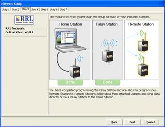
18 Step 3 is a transition screen. At this point you should connect the RRL Gold Figure 4-5 RRL Gold Software Wizard Transition Screen Station you are about to program to the Home Station computer using an RS232 cable (#106811). This screen will identify that you are about to program the Home Station, a Relay Station or Remote Station. Programming the Home Station is always first. This screen will show you your progress in configuring your RRL Network. It will indicate which RRL Stations have been programmed and which RRL Stations are left to program. # Figure 4-6 RRL Station Connected to a PC Page 14

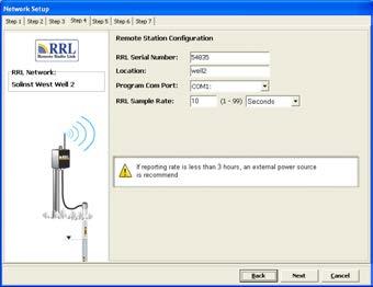
19 Step 4: Programming Your RRL Gold Station In Step 4, enter the serial number of the RRL Gold Station you are programming; the Location of the Station, i.e.: Home Station, Well 1, Relay Station 2 ; the Com Port being used to program the RRL Station; and the Sample Rate for that station (if different from the one set in Step 2). If you are programming the Home Station, you will select whether there is a Levelogger connected to the station. If there is not, you will skip to Step 6. If there is a Levelogger connected, or you are programming a Remote Station, you will proceed to Step 5. Figure 4-7 Programming a RRL Gold Station Page 15
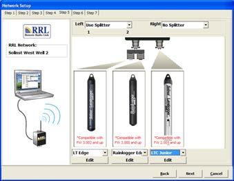
20 Step 5: Configuring Attached Leveloggers In this step you will select the number and types of Leveloggers connected to the RRL Gold Station. The connectors for Leveloggers on the RRL Gold Stations are identified as Right and Left. This assumes the RRL Station is facing with the black label towards you. If using a Splitter, the number 1 or 2 will identify the Leveloggers. The numbers 1 and 2 are labeled directly on the connections of each Splitter. If you are connecting a Rainlogger, you must program (Edit) it in order to enter a Rainfall Calibration Constant (the amount of rainfall per tip of the connected rain gauge). For each connection you will select the type of Levelogger attached. Select None for connectors with no Levelogger attached. After selecting the datalogger type from the drop down menu, an image of the selected datalogger will be displayed. To optionally set each datalogger to record in their internal memory, select Edit to begin entering data collection information. You must Edit the Rainlogger in order to enter a Rainfall Calibration Constant, but you do not have to set it to record independently. Select Next, without editing, if you do not want to set your Leveloggers to record independently. The firmware versions shown in red for each Levelogger, are the firmware versions that will work with STS/RRL Software Version Figure 4-8 Adding Leveloggers Page 16

21 If you want your datalogger to record and store readings in its internal memory, independent of RRL operation, select To stop the Levelogger from independently logging, select Editing Levelogger Information Figure 4-9 Levelogger Information Window If you are programming a number of Leveloggers with the same settings, select Save Settings after programming the first Levelogger. Select Load Settings when starting to set up your next Levelogger to apply the saved settings. The Levelogger Edge, Levelogger Junior Edge and Barologger Edge can be adjusted for Altitude and Density post data collection using the Data Compensation Wizard in the Levelogger Software. The Levelogger Information window includes Levelogger Serial Number, Well Location, Altitude and Density Adjustment (Levelogger Gold and Junior models only), Sample Rate, and Memory Mode Selection. If you want your datalogger to record and store readings in its internal memory, independent of RRL operation, select, and fill in the Sample Rate and Memory Mode Selection fields. If you do not require independent logging, select, and the RRL Station will only collect a real-time reading from the Levelogger at the scheduled Sample Rate. There is no need to enter a Levelogger Sample Rate. Serial Number: Your Levelogger Serial Number will display after the System is started. Well Location: Input specific site / location information. Density Adjustment: (Levelogger Gold and Junior models only) Is used to adjust the range of the Levelogger based on the sample fluid density. The range for the density adjustment is from 0.9 kg/l to 1.1 kg/l. Uncheck the Density Adjustment field to disable the Density Adjustment function. Altitude: (Levelogger Gold and Junior models only) In feet or meters above sea level, at which the logger is actually deployed, is input in the altitude field. Water column equivalent pressure decreases with altitude at a rate of approximately 1.2:1000 in the lower atmosphere below 5000 m. You can compensate for this by entering an elevation Page 17
22 The default sample rate is set to 15 minutes. The LTC Levelogger Junior has a minimum sampling rate of 5 seconds. The Levelogger Gold and Levelogger Junior can be set from 0.5 seconds to 99 hours. In Slate Logging, the datalogger will stop recording readings after its memory is full. Therefore, Continuous Logging is recommended for long term monitoring applications. between ft below sea level and 16,400 ft (or -300 m and 5000 m) above sea level. The readings will then be automatically compensated for elevation. Sample Rate: Is linear. Linear refers to a set time interval between collection of readings. Sample Rate can be any number from seconds to 99 hours for the Levelogger Edge. The Levelogger Junior Edge can be set to record from 0.5 seconds to 99 hours. Memory Mode Selection: There is a choice of Continuous Logging (wrap around) or Slate Logging. In Continuous Logging the new log is started at the end of any previous log and continues logging, eventually recording over the first logged data. As one of the download options is to Append Data, Continuous Logging can be a preferred choice when logging long-term. In Slate Logging the new log is also started at the end of any previous log, but will stop recordings when the memory is full, so that the beginning of the current log will not be written over. The Levelogger Junior Edge, LTC Levelogger Junior, Rainlogger, and Levelogger Junior only record in Slate Mode. Page 18

23 Setting Up Levelogger Measurement Parameters In the lower portion of the Levelogger Information screen is the window for setting channel parameters. The software will detect the available channels when the Levelogger Information settings are read. The only units available for the Levelogger Junior, LTC Levelogger Junior, Levelogger Gold and Barologger Gold are m (default), cm, and ft. The Levelogger Junior, LTC Levelogger Junior, Levelogger Gold and Barologger Gold only measure in ºC. For the Level Channel, you can set the following parameters: Identification describes the measurement parameter of the channel and has already been configured as LEVEL. The Level Channel monitors water column equivalent pressure. The Identification field will be the data column heading and graph line name when viewing the data. Units refers to the channel s units of measurement. There are six units of measure available for the user to select: m (default), cm, ft, kpa, mbar, and psi. When using a Barologger Edge, the options are kpa (default), mbar, and psi. Offset refers to an offset correction, such as the distance between the tip of the Levelogger and the monitoring well cap or static water level. It is recommended that the value of 0.00 be used for offset as this keeps all subsequent readings relative to the tip of the Levelogger. The offset range is to ft or -300 m to 5000 m. The Temperature Channel includes the following parameters: Identification describes the measurement parameter of the channel and has already been configured as TEMPERATURE Units refers to the channel s units of measurement. For the Levelogger and Barologger Edge, the temperature channel can be set to ºC (default) or ºF. Figure 4-10 The Temperature Channel Page 19


24 To calibrate the LTC Levelogger Junior, use Levelogger Software Version 4.0 or higher. The LTC Levelogger Junior should be calibrated before starting any new project. Conductivity measurements can be converted to Specific Conductance measurements or Salinity values using the Data Compensation Wizard in the Levelogger Software. LTC Levelogger Junior Measurement Parameters: Identification describes the measurement parameter of the channel and has already been configured as Conductivity.The Identification field will be the channel heading, data column heading and graph line name when viewing the data. Unit refers to the channel s units of measurement. There are two units of measure available for the user to select: ms/cm or μs/cm. The Temperature Coefficient field allows you to choose the actual conductivity ( Conductivity ) at the current temperature or select Specific Conductance ( Spec. Cond.) measurement in which the conductivity reading is temperature compensated to the standard of 25ºC. The Temperature Coefficient default is 2.00 for Specific Conductance readings. The Temperature Coefficient should not be adjusted, unless you know the value specific to the solution you are measuring. Figure 4-11 LTC Levelogger Junior Measurement Parameters Page 20

25 Your Rainlogger Edge must be using firmware version or higher. Your Rainlogger firmware must be upgraded to or higher. The Sample Rate and Max Rainfall options included in Rainlogger firmware versions previous to 2.000, are no longer available. You must program (Edit) your Rainlogger in order to enter a Rainfall Cal Constant (the amount of rainfall per tip of the connected rain gauge), but you do not have to set it to record independently. Rainlogger Measurement Parameters: There is one channel of measurement for Rainloggers. The RainFall Channel records each tip time by the connected tipping-bucket and outputs the amount of rainfall per tip (input Rainfall Cal Constant). When an RRL Gold Remote Station reports Rainlogger data to the Home Station, it will send the accumulated rainfall amount per sample period (based on RRL Station Sample Rate). To determine the exact time that a tip occurred, the Rainlogger would have to be set to record in its own internal memory, which stores each tip event. Identification describes the measurement parameter of the channel and has already been configured as RainFall. The channel can be re-named to suit each project. The Identification field will be the channel heading, data column heading and graph line name when viewing the data. Identification is limited to 32 characters. Units refers to the channel s unit of measurement. There are two units of measure available for the user to select: mm or in. The Rainfall Cal Constant field allows you to enter the calibration factor for the tipping-bucket you will be using. The calibration factor is the amount of rainfall depth (mm, in) per tip. The calibration factor should be indicated on a label on the tipping-bucket device or in the manufacturer s documentation. Input the calibration factor in mm or inches. When an RRL Gold reports Rainlogger data to the Home Station, it will send the accumulated rainfall per sample period (based on RRL Station Sample Rate). Figure 4-12 Rainlogger Measurement Parameters After all Leveloggers have been entered and programmed as desired, proceed to Step 6. Page 21

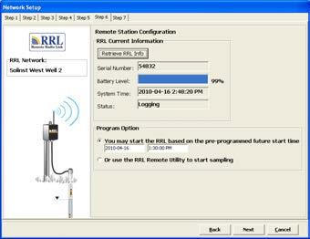
26 Step 6: Confirm Station Settings In this step, select Retrieve RRL Info. This will apply all the settings to the RRL Gold Station and retrieve information from that station to confirm it has been successfully programmed. Figure 4-13 RRL Station Information Serial Number: Should match the serial number you entered in Step 2. Battery Level: The internal battery level of the RRL Gold Station System Time: The internal system time of the RRL Gold Station Status: The RRL Station is Logging or Waiting for Update. You will also select whether you wish to start this station using the Programmed Start Time entered in Step 2, or use the Remote Utility to start the station at a different time (see Section 5). Sampling based on the Future Start Time: The RRL Gold Station will start sampling based on the start time you set in Step 2. Use RRL Remote Utility to Start Sampling: The RRL Gold Station will stay in stop mode. To start sampling, you have to use the RRL Remote Utility (see Section 5). If you are programming the Home Station or one of multiple Remote or Relay Stations, you will be prompted to the transition screen in Step 3. This will show which stations have been programmed, and which stations are left to program. Stations that have been programmed will be identified as Done. You will proceed through Steps 3 to 6 until all stations have been programmed. See Figures 4-14 and Page 22

27 Figure 4-14 Configuring a Relay Station Figure 4-15 Configuring a Remote Station Page 23


28 Step 7: RRL Network Configuration Summary Figure 4-16 RRL Network Configuration Summary After all settings have been programmed for each RRL Gold Station in the network, Step 7 will display a summary of all the settings. You can print a copy of this summary for your records. Selecting Finished will open the STS Administrator window and start the Communication Agent. Once all stations have been programmed, it is recommended you start each station logging as a test in the office. This can be done using the Remote Utility (see Section 5). After each station is started, and has contacted the Home Station, the serial numbers and types of Loggers connected to the station will be shown in the Administrator Window. You can print a copy of this screen for each station as a record, and refer to it when installing your stations in the field. Figure 4-17 RRL Network in Administrator Window Page 24


29 Selecting Delete when a RRL Gold Network is highlighted, will not allow you to delete that network, until all stations in that network are deleted first Editing RRL Gold Networks Editing the Network Setup When you select a RRL Gold Network from the list in the STS Administrator window, choosing Edit Site Setup will allow you to Edit Network Setup or Add new Site to Network. Figure 4-18 Editing a RRL Gold Network When you select Edit Network Setup there are two options. You can choose to update each RRL Gold Station in the network by connecting them to the PC through the RS232 Port, or the Remote Schedule Update allows you to make the changes in the software, and the new settings will be applied to each RRL Gold Station with their next scheduled report to the Home Station. If you choose Remote Schedule Update, there are two steps. Step 1 allows you to make changes to the network settings, including: Project Identification, Network ID, and Radio Power. You can also restart the network with a new Sampling Rate, Report Rate, and Report Duration. Figure 4-19 Editing a RRL Gold Network - Step 1 Page 25

30 The screenshot at right shows 4 steps. This is because the option to update each RRL Gold Station through the serial port was selected. Steps 2 and 3 in this case are for connecting the two Remote RRL Gold Stations in the network, to the PC and updating their settings. Step 4 provides the summary. Figure 4-20 Editing a RRL Gold Network - Step 2 Step 2 will provide you with a new Network Configuration Summary that you can print for your records. If you select to update each RRL Gold Station through the serial port, after changing the setting in Step 1, you will be prompted to connect each RRL Gold Station to the Home Station PC with an RS232 cable, and update them with the new network settings. The last step will provide you with a Network Configuration Summary for your records. When you select Add new Site to Network, you will be prompted though Steps 2 through 7 of the software wizard. Page 26


31 Selecting Delete when a RRL Gold Station is highlighted will prompt a window asking if you are sure you want to delete that station. You must delete all stations in a site before the entire network can be deleted. Editing RRL Stations When you select a specific RRL Gold Station from the list in the STS Administrator window, choosing Edit Site Setup will allow you to edit the settings for that RRL Station. Figure 4-21 Editing a RRL Station There are three steps when editing a RRL Gold Station s settings. Step 1 allows you to enter a new Location, Program Com Port and Sample Rate. Step 2 allows you to add or edit the attached Leveloggers and their settings. Step 3 retrieves the new settings and allows you to choose between applying the changes to the RRL Station by connecting it to the PC, or the Remote Schedule Update allows you to make the changes in the software, and the new settings will be applied to the RRL Station with its next scheduled report to the Home Station. Figure 4-22 Editing a RRL Gold Station - Steps 1 and 3 Page 27

32 RRL Remote Utility Version should be used with STS/RRL Software Version RRL Remote Utility The RRL Remote Utility provides a convenient way to communicate with programmed RRL Gold Stations in your office or in the field, as well as perform diagnostic checks and firmware updates. Figure 5-1 RRL Remote Utility To open the RRL Remote Utility, click, or click the Start button and select: Programs > Solinst > rrlg_remote > RRL Remote Utility The RRL Remote Utility can be used to test radio communication between a Remote or Relay Station and the Home Station, check RRL Gold Station settings and status, test communication with the attached Leveloggers, and stop or start the RRL Station logging (when selected in Step 2 of the software wizard). The Remote Utility also includes a self-test function. The function performs a series of self-tests on a RRL Gold Station to check for problems with the battery, memory, etc. To use the RRL Remote Utility, connect the RRL Gold Station to a PC with a RS232 cable, select the COM port to which the Station is connected and click Retrieve Info to display the settings from the RRL Gold Station. Page 28

33 The Radio Communication Test is a convenient tool when determining the final location of you Remote Station in the field and the proper Radio Power setting for that station. The Remote Utility has the following functions: Radio Communication Test: Click Radio Test to initiate the test. If the communication between the RRL Gold Station and the Home Station is successful, the Home Station Communication Test Passed message will be shown. Figure 5-2 Home Station Communication Test Datalogger Communication Test: Click the Test button beside the datalogger image to initiate the test. If the communication is successful, the Probe Communication Test Passed message will be shown. Figure 5-3 Datalogger Communication Test Start Logging: If the RRL Gold Station is in idle mode Start will be displayed in the Remote Utility main menu. To start logging, click Start, and Stop will then be displayed to indicate that the RRL Gold Station is in logging mode. Stop Logging: If the RRL Gold Station is in logging mode Stop will be displayed in the Remote Utility main menu. To stop logging, click Stop. A message Data Logging and Reporting will be terminated. Do you want to continue? will be shown. Click Yes to continue. Start will be displayed to indicate that the RRL Gold Station is in idle mode. Page 29

34 5.1 Self Test The Remote Utility also includes a self-test function. The function performs a series of tests on a RRL Gold Station to check for problems with the battery, memory, etc. If any of these tests fail, then a report should be created and sent to Solinst Technical Support. To execute this function, select Self Test. Figure 5-4 RRL Gold Station Self Test Page 30

35 STS/RRL Gold Software Version is compatible only with the latest RRL Gold Firmware Firmware Upgrade Instructions RRL Gold Stations have been designed with firmware that is easy to update whenever useful new functions or other improvements become available, as with software releases. To determine the current firmware version on an RRL unit, connect it to the PC with a RS232 cable and open the RRL Remote Utility. Select the COM port to which the unit is connected and click Retrieve Info to display the settings, including firmware version, from the RRL Station. To update the firmware in your RRL Gold Station, go to the Solinst Website at: where you can obtain a link to the RRL firmware update file that is contained within a Zip Archive. Ensure you unzip the archive to access the *.ssf firmware file. Figure 5-5 Firmware Upgrade Utility 1) Use an RS232 serial cable to connect the RRL Gold Station to the PC. 2) Ensure you have installed the RRL Remote Utility Software on your PC. There will be a Firmware Upgrade Utility shortcut added to your desktop. 3) Open the Firmware Upgrade Utility and make sure the Baud Rate is set to ) Click the Open button, which should open a file dialog asking for the firmware file (*.ssf) to upload. Navigate to where the firmware file was saved on your PC, then click on the file and click Open. 5) Check the Firmware File Information box to make sure that the opened file is the right one. 6) Click the Upload Firmware button to start the firmware upload process. 7) If a communication error occurs and is indicated in the Information Window either before the Verified Program Checksum message or after the Program Information Section, then restart the upgrade process. Note: When conducting a firmware upgrade, DO NOT interrupt the process prior to completion (This may take 30 minutes). If the notice The firmware version in the RRL is more recent, continue the firmware updated? appears, you must select Continue. Selecting No or otherwise interrupting the upgrade process will make the RRL Station unable to communicate with STS/RRL Software. To correct this, the firmware must be re-upgraded, and allowed to fully complete installation. Installation is not complete until a note appears at the base of the program window indicating Firmware Upgrade Completed. Page 31
 antenna, six (6) 3.6V AA lithium batteries, and dust caps to protect connections when not in use. 2.")
36 See Section 2.2 for connecting Leveloggers and Splitters. 6 RRL Gold Station Hardware Setup RRL Gold Stations come standard with a built-in 900 MHz radio module. Also standard is a 6" half wave (2.1 dbi) antenna, six (6) 3.6V AA lithium batteries, and dust caps to protect connections when not in use. 2.2 Connecting Leveloggers and Splitters Dust Cap for External Power Connection Antenna (pt# ) Dust Cap for RS232 Connection Dust Caps for Levelogger Connections Batteries (3 x 2 packs) (pt# ) Figure 6-1 RRL Gold Station (pt# ) Page 32

37 The RRL Gold Home Station and any Relay Station requires an external power supply. Where possible, use lower Radio Power settings and/or longer Report intervals to conserve Remote Station Battery life. 6.1 Power Sources and Antennas Power Supply RRL Stations come standard with six (6) 3.6V AA lithium batteries. The batteries must be installed for proper operation, even if you use an additional external power source. The life of the battery varies depending on the frequency of your Sample and Report Rates. The following are estimates based on the standard lithium batteries, with the Radio Power setting at 1 Watt. With the Radio Power set at 100 mw, the battery life increases by about 10% of the estimates below. RRL Gold Stations can also be powered by six (6) user-supplied 1.5V AA alkaline batteries. With alkaline batteries, the battery life will be about 40% of the estimates below. Sample Rate Report Rate Battery Life Every 5 Minutes Every Hour 114 Days Every 15 Minutes Every 6 Hours 425 Days If your Reporting Rate is less than 3 hours, an external power source is recommended. Every Hour Every 12 Hours 680 Days Every 12 Hours Every Day 895 Days Every 15 Minutes Every 3 Days 810 days Every Hour Every 7 Days 1078 Days Every 12 Hours Every 14 Days 1200 Days Table 6-1 Battery Life Estimates (6 AA lithium batteries at 1 Watt setting) The internal RRL Gold batteries are not rechargeable. RRL Gold Home Stations and Relay Stations require an external power supply. Remote Stations may also require an external power supply, depending on your Sample and Report Rates and site needs. Solinst supplies a cable for connecting to an AC power source and a cable to connect to a user-supplied 12V battery or solar panel. Cables are connected to the RRL Gold Station beside the antenna connection (see Figure 6-2). Rechargeable batteries can not be used inside any RRL Units (Home, Relay, Remote), as the voltage would be to low. Figure 6-2 External Power Cable Connection Page 33


38 The six (6) 3.6V AA batteries must be installed for proper operation, even if using an additional external power source. RRL Gold Stations can be powered by: 1. External AC (mains) power. Simply use the Solinst supplied adaptor cable (pt# North American) shown in Figure 6-3 to connect the RRL to an AC power source. The adaptor has input from VAC. See connection diagram in Figure 6-4. Figure 6-3 AC Power Adaptor Cable Assembly (pt# ) # Figure 6-4 Direct AC (mains) Connection Page 34

 RRL Connection + (12V Connection) Figure 6-5 Solar/12V Cable Assembly (pt# 109452) User-supplied 12V Lead Acid Battery 60 Amp-hour Min.")
39 + - Remote Radio Link User Guide The external 12V battery should have a minimum 60 Amp-hour rating. It is recommended you have a higher Amp-hour rating if you have a high report rate, or if your station is in a very remote location and you are not able to replace the battery easily. 2. Using the Solinst-supplied Solar/12 Volt Cable Assembly (pt# ), shown in Figure 6-5, to connect to a user-supplied external 12V lead-acid battery (minimum 60 Amp-hour). See connection diagram in Figure (Ground Connection) RRL Connection + (12V Connection) Figure 6-5 Solar/12V Cable Assembly (pt# ) User-supplied 12V Lead Acid Battery 60 Amp-hour Min. # Figure 6-6 External 12V Lead-Acid Battery Connection Solar panel power will not be available at night or during very cloudy conditions. If Reporting sessions are scheduled for these times, the internal batteries will be used. 3. Using the Solar/12 Volt Cable Assembly (pt# ) to connect to a user-supplied Solar Panel (minimum 15 watt) with a built-in regulator for 12V. See Figure 6-7 for the connection diagrams. 15W Min. User-supplied 12V Regulated Solar Panel # Figure 6-7 External Solar Panel Connection Page 35


40 4. Using the Solar/12 Volt Cable Assembly (pt# ) to connect to an external user-supplied 12V lead-acid battery (minimum 12 Amp-hour rating), trickle charged with a Solar Panel (minimum 15 W with a regulator for 12V). See connection diagram in Figure 6-8. # W Min. User-supplied 12V Lead Acid Battery 12 Amp-hour Min. User-supplied Solar Panel with 12V Regulator Figure 6-8 External 12V Lead-Acid Battery with Solar Panel Connection Page 36
41 For more information on installing Leveloggers in the field, see the Levelogger User Guide or STS Gold User Guide. Solar Panels A solar panel is connected to a RRL station using the Solar/12 Volt Cable Assembly (see Figure 6-7). The solar panel is user-supplied. The panel should output a minimum of 13V open circuit in order to effectively re-charge the batteries. As a guideline, the solar panel should be at least 15 Watts. Higher wattage panels are also suitable. The solar panel must also include a regulator to handle external battery charging cycle. Antennas RRL Stations come standard with an omnidirectional antenna. The antenna should always be mounted on the outside of any enclosure for maximum communication distance, as they communicate via line-of-sight transmission. 900 MHz radios can communicate over distances up to 20 miles (30 km). To maximize communication distances between RRL Stations, an optional High Gain Antenna is available (pt# ). Before sourcing any other power accessories or antennas to use with RRL Stations, refer to the radio module manufacturer s product manuals for approved devices at: Installing RRL Gold Stations in the Field RRL Gold Stations are designed to fit inside 4.5" (115 mm) diameter wells for discrete placement. Location and Communication Considerations When using radio communication, you must take extra care when locating the Remote Stations. RRL Gold radios communicate with each other via lineof-sight. They must be able to see each other in order to have effective communication. The path between radio antennas should not be through trees or perpendicular to the sides of flat buildings. The communication distances given for each radio module, with standard antennas, are guidelines. Each project is site specific, and will require testing and planning before installing a RRL Gold Network. A communication range test can be performed prior to installation between the Home Station and the Remote or Relay Station using the RRL Remote Utility (see Section 5). Tests can be done using different Radio Power settings (see Section 4.1) to determine the ideal setup for your site. Always start with the lowest Radio Power setting, as this will conserve battery power. (Longer Report intervals will also conserve battery power). Field tests will allow you to determine if you need an additional power source due to a higher Radio Power setting, or the addition of a higher gain antenna to increase communication distances. Adding a Relay Station should be the last option to increase your communication distance, or if there is an obstacle (such as buildings or trees) that you have to get your RF signal around. Page 37


42 7 Viewing Site Data Access Database The Access database can be queried by your own macros or applications, to automatically check for updates and display the data in your own program, on a website, or in any way you choose. Data received in each report from a RRL Gold Station is placed in a Microsoft Access database (.mdb files) on the Home Station computer. New data is appended to the existing database. The program will save data downloaded to the following default directory: <C:\Program Files\Solinst\STS_Gold\db> Figure 7-1 RRL Gold Database Folder Figure 7-2 RRL Gold Access Files Figure 7-3 RRL Gold Access Data Page 38


43 View Using STS/RRL Software The STS/RRL Gold Software can be used for a quick check of the latest readings. Data can also be exported using the Software as *.xle, *.lev or *.csv files for use in other programs. To view data from a specific site using the STS/RRL Gold Software, open the Administrator window and select a RRL Network or station from the list. Click on Display Data. Select the RRL Gold Station from the list that opens and click OK. Figure 7-4 Select RRL Gold Station Figure 7-5 RRL Gold Station Data Window The data will be displayed in a table at the top of the window, the bottom portion of the window will show the data graphed. Data from each Levelogger is shown in a separate tab (identified by serial number), Station data, including battery voltage is also displayed in a separate tab. A summary of all data is in a separate tab. Page 39

44 Barometric Compensation of Levelogger data can also be performed using Levelogger Software s Compensation Wizard. RRL data files can be exported using STS/RRL Gold Software as *.xle or *.lev files and opened in Levelogger Software for automatic compensation. See the Levelogger User Guide for more details. 7.1 Barometric Compensation Submersed Leveloggers measure total or absolute pressure (water column equivalent + barometric pressure). In order to accurately determine the true changes in water level only, Levelogger data must be barometrically compensated. Levelogger data can be barometrically compensated using data from a local Barologger (one Barologger can cover all Leveloggers within a 20 mile/ 30 km radius or per 1000 ft/300 m change in elevation) and the Barometric Compensation application in the STS/RRL Gold Software (Version or higher). The Levelogger and Barologger must have the same time stamp in order for the compensation to be successful. Compensation simply involves subtraction of the barometric reading from the corresponding Levelogger reading. To begin the compensation, click the Barometric Compensation tab on the STS/RRL Administrator Window. The Levelogger and Barologger must have the same time stamp in order for the compensation to be successful. Figure 7-6 Barometric Compensation Window In the Barometric Compensation Window, from the Enable Barometric Compensation list, check the RRL Station that you wish to compensate, and RRL Station (or STS Site) that will provide the Barologger for the compensation. In the Select Barologger from Site section, select the RRL Station (or STS Site) that contains the Barologger you wish to use for the compensation, and identify the Barologger by its position (Logger ID) on the RRL Station (or STS Site). Page 40
. If you do not enter these values, the Software will assume all altitudes to be 0 (sea level).")
45 To account for different altitudes in your compensation, enter the Altitude at which the Barologger is deployed. You will also enter the following for each connected Levelogger (does not apply for Rainloggers). If you do not enter these values, the Software will assume all altitudes to be 0 (sea level). Reference Altitude: i.e. surface datum point, top of well casing or well head. Static Water Level from Reference Altitude: enter the distance between the Reference Altitude and static water level (i.e. manual water level meter measurement). Click OK to complete the compensation. To view the compensated data, click the Display Data tab on the STS/RRL Administrator Window. Check the sites that you wish to view from the list provided. The data will be displayed in a table at the top of the window, the bottom portion of the window will show the data graphed. Data from each Levelogger is shown in a separate tab (identified by serial number). To view raw Levelogger data (uncompensated), uncheck Show Compensated Data. The compensated data will be in the units that the Levelogger was programmed to record in. E.g.: if your Barologger was set to record in psi and your Levelogger was set to record in feet, the compensated data will automatically be converted to feet. A Barologger Edge or Barologger Gold can be used to compensate the data from any version of Levelogger. Figure 7-7 View Compensated Data Page 41

46 7.2 Graphing Options Click the Graph Option icon to open the Graph Option Dialog. The Graph Dialog is shown in Figure 7-8. The Line Option is used to adjust the style and colour of the line in the graph for each channel. The user can also select the shape of the data marker or remove the data marker. The Title and Axis Option is used to enter the title of the graph and change the Y axis label or user selected scale. Check the Best Fit box to enable the software to determine the best fit scale. If the Best Fit box is not checked, the user has to enter a maximum and minimum value of the selected channel. The X axis is logging time. Figure 7-8 Graph Option Dialog Box Page 42


47 7.3 File Export Data can be exported in *.csv (comma separated value), *.xle or *.lev (Levelogger) file formats by clicking Export Data while viewing the site data. The *.csv file format is supported and can be imported by most spreadsheet programs, *.xle and *.lev files can be imported by Levelogger Software (only version 4.0 and up for *.xle files), where data compensations can be performed. Clicking will display a drop down menu where you can select to export as a *.csv, *.xle or *.lev file. For more information on data compensations using Levelogger Software, see separate User Guide. Exporting as a *.csv file will export all of the data from the selected site. You can save this file where you choose and give it a unique file name. You can not export Rainlogger Data as a.lev file. Figure 7-9 Save Exported File Exporting as a *.xle or *.lev file, allows you to select a specific Levelogger File. Choose the desired file from the list. The file name will include the datalogger serial number, and can be saved in a folder of your choice. This file can be imported by the Levelogger Software, where barometric and other compensations can be performed. (See Levelogger User Guide for more information). Figure 7-10 Saving Levelogger Data Page 43

48 Export All Data Data from all RRL Gold Stations and STS Gold Sites can be exported at one time, using the Export all Stations Data function in the File menu. There is the option to save all the data in *.xle, *.lev or *.csv files. Exporting data as *.xle or *.lev files will save data from each Levelogger into separate files. Exporting as *.csv files will save data from each RRL Gold Station or STS Gold Site into separate files. Figure 7-11 Export All Stations Data Page 44
STS Telemetry System User Guide
 STS Telemetry System User Guide Version 1.1.1 December 1, 2010 STS Telemetry user Guide 1 Introduction to STS Telemetry and Leveloggers 1 - Levelogger Gold 2 - Barologger Gold 3 - Levelogger Junior 3
STS Gold Telemetry System User Guide
 STS Gold Telemetry System User Guide Version 1.0.2 August 17, 2009 - Table of Contents 1 Introduction to STS Telemetry and Leveloggers 4 - Levelogger Gold 5 - Barologger Gold 6 - Levelogger Junior 6 -
The CO2 Sensor Calibration Kit
 The CO2 Sensor Kit For use with all BAPI CO 2 Sensors Instruction Manual CO 2 Kit Product Identification and Overview BAPI s CO 2 Sensor Kit is designed to calibrate and verify the operation of all BAPI
Instruction Manual ABM HART Gateway Software. Instruction Manual Revision A.1
 Instruction Manual ABM HART Gateway Software Instruction Manual Revision A.1 Table of Contents Section 1: Getting Started... 3 1.1 Setup Procedure... 3 1.2 Quick Setup Guide for Ultrasonic Sensors... 11
MINIMUM SYSTEM REQUIREMENTS
 Quick Start Guide Copyright 2000-2012 Frontline Test Equipment, Inc. All rights reserved. You may not reproduce, transmit, or store on magnetic media any part of this publication in any way without prior
Field Device Manager Express
 Honeywell Process Solutions Field Device Manager Express Software Installation User's Guide EP-FDM-02430X R430 June 2012 Release 430 Honeywell Notices and Trademarks Copyright 2010 by Honeywell International
ProLink Radio. 900 MHz SDI-12 Data Radio Scienterra Limited. Version A-0x0C-1-AC 20 October 2009
 ProLink Radio 900 MHz SDI-12 Data Radio Scienterra Limited Version A-0x0C-1-AC 20 October 2009 For sales inquiries please contact: ENVCO Environmental Collective 31 Sandringham Rd Kingsland, Auckland 1024
WEB I/O. Wireless On/Off Control USER MANUAL
 Wireless On/Off Control Technical Support: Email: support@encomwireless.com Toll Free: 1 800 617 3487 Worldwide: (403) 230 1122 Fax: (403) 276 9575 Web: www.encomwireless.com Warnings and Precautions Warnings
Contents. Overview Introduction...3 Capabilities...3 Operating Instructions Installation...4 Settings... 5
 User s Manual Contents Overview................................................................. 3 Introduction..............................................................3 Capabilities...............................................................3
Table 1. Placing the Sensor in the Sensor Cradle. Step Instruction Illustration
 Table 1. Placing the Sensor in the Sensor Cradle Step Instruction Illustration 1. A. Check "U-shaped" Positioner. The number pointing towards the Sensor (1 or 2) must correspond with the Sensor's size.
INSTRUCTION MANUAL FOR ULTRASONIC/MICROWAVE SENSORS
 INSTRUCTION MANUAL FOR ULTRASONIC/MICROWAVE SENSORS 1)Install PROBE_GatewayPC Software on PC.Remove previous installation. In Windows Control Panel go to the Programs and Features, select Probe_GatewayPC_Net
LD2342 USWM V1.6. LD2342 V1.4 Page 1 of 18
 LD2342 USWM V1.6 LD2342 V1.4 Page 1 of 18 GENERAL WARNINGS All Class A and Class B marine Automatic Identification System (AIS) units utilize a satellite based system such as the Global Positioning Satellite
Table Of Contents Overview of the operating buttons... 4 The functions of the datalogger... 5 How to start logging from the default settings...
 Table Of Contents 1. Overview of the operating buttons... 4 2. The functions of the datalogger... 5 2.1 LOG... 5 2.2 METER... 5 2.3 REVIEW... 5 2.4 TIME / date... 5 2.5 START time / date... 5 2.6 INT log
Faculty of Electrical & Electronics Engineering BEE4233 Antenna and Propagation. LAB 1: Introduction to Antenna Measurement
 Faculty of Electrical & Electronics Engineering BEE4233 Antenna and Propagation LAB 1: Introduction to Antenna Measurement Mapping CO, PO, Domain, KI : CO2,PO3,P5,CTPS5 CO1: Characterize the fundamentals
AgGPS RTK 450 MHz Mobile Base Station and Rover Unit: Setting Up
 6 August 2007 AgGPS RTK 450 MHz Mobile Base Station and Rover Unit: Setting Up This Support Note describes how to set up a Trimble AgGPS RTK 450 mobile base station and rover radio. Instructions apply
WPR400 Wireless Portable Reader
 P516-098 WPR400 Wireless Portable Reader User guide Para el idioma español, navegue hacia www.schlage.com/support. Pour la portion française, veuillez consulter le site www.schlage.com/support. Contents
Hytera. PD41X Patrol Management System. Installation and Configuration Guide
 Hytera PD41X Patrol Management System Installation and Configuration Guide Documentation Version: 01 Release Date: 03-2015 Copyright Information Hytera is the trademark or registered trademark of Hytera
BANTAM INSTRUMENTS SOFTWARE USER S MANUAL MIL-STD-461E PRE-COMPLIANCE MEASUREMENT SYSTEM MODEL EMC-461. Model EMC-461 Software User s Manual
 BANTAM INSTRUMENTS MIL-STD-461E PRE-COMPLIANCE MEASUREMENT SYSTEM MODEL EMC-461 SOFTWARE USER S MANUAL MIL-STD-461E PRE-COMPLIANCE MEASUREMENT SYSTEM MODEL EMC-461 Software User s Manual BANTAM INSTRUMENTS
MAXI Remote Location Kit MRLK 900 Installation and Configuration Manual
 MAXI Remote Location Kit MRLK 900 Installation and Configuration Manual 01/18 635079 Table of Contents Introduction... 3 Materials Included... 3 Setup Overview... 4 Radio Configuration Overview:... 4 FreeWaveTool
Connecting Mains Electrical Power
 Tide Level Monitoring Instrumentation The following documentation details the electrical installation for the tide level monitoring instrumentation and also a summary of the logger configurations required
MADEinUSA OPERATOR S MANUAL. RS232 Interface Rev. A
 MADEinUSA OPERATOR S MANUAL RS232 Interface 92-3006 Rev. A www.iradion.com Iradion Laser, Inc. 51 Industrial Dr. N. Smithfield, RI 02896 (410) 762-5100 Table of Contents 1. Overview... 2 2. Equipment Required...
GENERAL INFORMATION BATTERIES: WHAT DO I NEED TO KNOW ABOUT BATTERIES?
 724-1409 FAQS We are weather enthusiasts like you and know proper running equipment is important. These FAQS provide valuable information on setup, positioning, and troubleshooting your station. We recommend
TEK-TROL HART GATEWAY SOFTWARE. Operating Instruction Manual.
 TEK-TROL HART GATEWAY SOFTWARE Operating Instruction Manual www.tek-trol.com Table of Contents 1 Getting Started... 2 1.1 Setup Procedure... 2 1.2 Quick Setup Guide for Radar Sensors... 10 2 Level device
APX Mobile and Portable Automated Test and Alignment
 APX Mobile and Portable Automated Test and Alignment Software Updates First things first! Be sure to check that you are running the latest software versions for the 8800SX and its applications. Visit the
Radio Link Starter Kit
 Radio Link Starter Kit Installation Manual BARTLETT Instrument Co. 1032 Avenue H Fort Madison, IA 52627 319-372-8366 www.bartinst.com Table of Contents Radio Link Starter Kit Manual... 3 System Requirements...
INDEX...2 INTRODUCTION...3 IMPORTANT NOTES...3 INSTALLING THE SOFTWARE...3 ST-965 PROGRAMMING SOFTWARE...6
 ST-965 KW/D SMARTRUNK II & SMARTRUNK XPRESS Logic board Programming Software 2.9e User s Guide Revision R2.9.8 12/30/2008 INDEX INDEX...2 INTRODUCTION...3 IMPORTANT NOTES...3 INSTALLING THE SOFTWARE...3
Issue No: MG025 Date: 05 June McMurdo SmartFind R5 GMDSS Radio IMO MSC. 1/Circ Update procedure
 Installation SERVICE BULLETIN Issue No: MG025 Date: 05 June 2017 McMurdo SmartFind R5 GMDSS Radio IMO MSC. 1/Circ. 1460 Update procedure Product Affected: McMurdo R5 GMDSS VHF Handheld Radio Reason: Compliance
SRT Marine Technology. LD2342 V1.4 Page 1 of 22
 LD2342 V1.4 Page 1 of 22 LD2342 V1.4 Page 2 of 22 2 LD2342 V1.4 Page 3 of 22 GENERAL WARNINGS All marine Automatic Identification System (AIS) units utilise a satellite based system such as the Global
Vinyl Cutter Instruction Manual
 Vinyl Cutter Instruction Manual 1 Product Inventory Inventory Here is a list of items you will receive with your vinyl cutter: Product components (Fig.1-4): 1x Cutter head unit complete with motor, plastic
INSTRUCTION MANUAL IP REMOTE CONTROL SOFTWARE RS-BA1
 INSTRUCTION MANUAL IP REMOTE CONTROL SOFTWARE RS-BA FOREWORD Thank you for purchasing the RS-BA. The RS-BA is designed to remotely control an Icom radio through a network. This instruction manual contains
Operations Manual Edition 3.1
 Operations Manual Edition 3.1 MREL GROUP OF COMPANIES LIMITED 1555 Sydenham Road, Kingston, Ontario K7L 4V4 Canada T: +1-613-545-0466 F: +1-613-542-8029 E: blasting@mrel.com www.mrel.com ii Copyright Information
Ground System Training Department
 Module 7: IPSTAR Uplink Access Test (IUAT) Ground System Training Department 2012-03-Standard (iuat1.14)-uti-101 THAICOM Public Company Limited Module Objectives At the end of the module the participant
LVTX-10 Series Ultrasonic Sensor Installation and Operation Guide
 LVTX-10 Series Ultrasonic Sensor Installation and Operation Guide M-5578/0516 M-5578/0516 Section TABLE OF CONTENTS 1 Introduction... 1 2 Quick Guide on Getting Started... 2 Mounting the LVTX-10 Series
Radio Link Starter Kit
 Radio Link Starter Kit Installation Manual BARTLETT Instrument Co. 1032 Avenue H Fort Madison, IA 52627 319-372-8366 www.bartinst.com Table of Contents Radio Link Starter Kit Manual... 3 System Requirements...
Featherweight GPS Tracker User s Manual June 16, 2017
 Featherweight GPS Tracker User s Manual June 16, 2017 Hardware Configuration and Installation The dimensions for the board are provided below, in inches. Note that with the antenna installed, the total
PRORADAR X1PRO USER MANUAL
 PRORADAR X1PRO USER MANUAL Dear Customer; we would like to thank you for preferring the products of DRS. We strongly recommend you to read this user manual carefully in order to understand how the products
Instruction Sheet OM-EL-USB-5. Counter, Event and State USB Data Logger
 Instruction Sheet OM-EL-USB-5 Counter, Event and State USB Data Logger OM-EL-USB-5 Counter, Event and State USB Data Logger FEATURES ORDERING INFORMATION Standard Data Logger (Data Logger, Software on
Antenna and Propagation
 Antenna and Propagation This courseware product contains scholarly and technical information and is protected by copyright laws and international treaties. No part of this publication may be reproduced
LincView OPC USER GUIDE. Enhanced Diagnostics Utility INDUSTRIAL DATA COMMUNICATIONS
 USER GUIDE INDUSTRIAL DATA COMMUNICATIONS LincView OPC Enhanced Diagnostics Utility It is essential that all instructions contained in the User Guide are followed precisely to ensure proper operation of
DPM Kit DK-1. Using the DPM Kit
 DPM Kit DK-1 Using the DPM Kit To ensure safe usage with a full understanding of this product's performance, please be sure to read through this manual completely. Store this manual in a safe place where
SAT SCD/ARGOS INSTRUCTION MANUAL
 INSTRUCTION MANUAL REVISION: 1/03 COPYRIGHT (c) 2000-2003 CAMPBELL SCIENTIFIC, INC. This is a blank page. WARRANTY AND ASSISTANCE This equipment is warranted by CAMPBELL SCIENTIFIC (CANADA) CORP. ( CSC
INDEX...2 INTRODUCTION...3 IMPORTANT NOTES...3 INSTALLING THE SOFTWARE...3 ST-965 PROGRAMMING SOFTWARE...6
 ST-965 VX/D SMARTRUNK II & SMARTRUNK XPRESS Logic board Programming Software 2.9e User s Guide Revision R2.9 10/10/2008 INDEX INDEX...2 INTRODUCTION...3 IMPORTANT NOTES...3 INSTALLING THE SOFTWARE...3
User manual. paper moisture meter RH5.1 with sword-sensor
 User manual paper moisture meter RH5.1 with sword-sensor version 2.0_en Schaller GmbH 2012 User manual Positioning the instrument Insert the sword-sensor into the stack for only approx. 10 cm, and push
5008 Dual Synthesizer Configuration Manager User s Guide (admin Version) Version valontechnology.com
 Version valontechnology.com") 5008 Dual Synthesizer Configuration Manager User s Guide (admin Version) Version 1.6.1 valontechnology.com 5008 Dual Synthesizer Module Configuration Manager Program Version 1.6.1 Page 2 Table of Contents
5008 Dual Synthesizer Configuration Manager User s Guide (admin Version) Version 1.6.1 valontechnology.com 5008 Dual Synthesizer Module Configuration Manager Program Version 1.6.1 Page 2 Table of Contents
ET Water SmartWorks Panel Installation Guide
 ET Water SmartWorks Panel Installation Guide You are installing a new piece of equipment that retrofits into an existing irrigation controller in order to create a weather-based irrigation control system.
New waveform generator plug in model 9923 adds user programmable battery discharge current waveform simulation to Prodigit DC Loads
 New waveform generator plug in model 9923 adds user programmable battery discharge current waveform simulation to Prodigit DC Loads 9923 Card Actual load current waveform on DSO 3311F Electronic load on
ADI-100 Interrupter. Operator s Manual. 526 S. Seminole Bartlesville, OK /
 ADI-100 Interrupter Operator s Manual 526 S. Seminole Bartlesville, OK 74003 918/336-1221 www.sescocp.com ADI - 100 Interrupter FEATURES Clock Accuracy 100% during GPS lock Clock Drift 30 µsec per degree
DragonLink Advanced Transmitter
 DragonLink Advanced Transmitter A quick introduction - to a new a world of possibilities October 29, 2015 Written by Dennis Frie Contents 1 Disclaimer and notes for early release 3 2 Introduction 4 3 The
Energate Foundation Meter Data Collector Installation Guide
 Energate Foundation Meter Data Collector Installation Guide The Meter Data Collector works with Foundation s built-in Meter Data Receiver. The collector attaches to the meter provided by your electricity
VRS20. Contents. Communications. Stay involved. RS232 Communications. 2/14/2014 VRS20 - Valeport
 Brian VRS20 View Edit History Contents Communications RS232 Communications RS485 Communications RS485 Address Mode SDI12 Communications Data Standalone Data Format GPRS Data Format Data Status Sampling
PIPELINE DEFECT MAPPER
 PIPELINE DEFECT MAPPER Receiver Colour Display C.A.T. Survey Graph ACVG Survey Graph GIS View General: The Pipeline Defect Mapper Kit designed and developed in such a way; to precisely locate and assist
CobraCam USB III Portable Inspection Camera with USB Interface Instruction Manual
 CobraCam USB III Portable Inspection Camera with USB Interface Instruction Manual 07/13 Test Equipment Depot - 800.517.8431 99 Washington Street, Melrose, MA 02176 TestEquipmentDepot.com CobraCam USB 3
GV-700 VIBE PORT. Installation and. Operating Manual
 GV-700 VIBE PORT Installation and Operating Manual This document may not be reproduced in any way without the prior written permission of the company. August 2016 2 GV - 700T TRANSMITTER GV - 701R RECEIVER
Installation & Quick Start Guide AIT2000 Class B AIS Transponder
 Installation & Quick Start Guide AIT2000 Class B AIS Transponder QUICK START AIT2000 - VR1.01 1. Introduction Congratulations on the purchase of your AIT2000 Class B AIS Transponder. It is recommended
Blue Bamboo P25 Device Manager Guide
 Blue Bamboo P25 Device Manager Guide Version of Device Manager: 1.1.28 Document version: 2.3 Document date: 2011-09-20 Products: P25 / P25-M / P25i / P25i-M BLUE BAMBOO Headquarters Blue Bamboo Transaction
BRB900 GPS Telemetry System August 2013 Version 0.06
 BRB900 GPS Telemetry System August 2013 Version 0.06 As of January 2013, a new model of the BRB900 has been introduced. The key differences are listed below. 1. U-blox GPS Chipset: The Trimble Lassen IQ
GNSS Conductor GF. User s Guide. (Document No. SE )
") GNSS Conductor GF User s Guide (Document No. ) www.furuno.com IMPORTANT NOTICE No part of this manual may be reproduced or transmitted in any form or by any means, electronic or mechanical, including photocopying
GNSS Conductor GF User s Guide (Document No. ) www.furuno.com IMPORTANT NOTICE No part of this manual may be reproduced or transmitted in any form or by any means, electronic or mechanical, including photocopying
Installation & Quick Start Guide CLB2000 Class B AIS Transponder
 Installation & Quick Start Guide CLB2000 Class B AIS Transponder QUICK START CLB2000 - VR1.01 1. Introduction Congratulations on the purchase of your CLB2000 Class B AIS Transponder. It is recommended
W500 Wildlink GPS Small Collar Logger/ W510 Wildlink GPS Glue-on Logger. User s Manual
 W500 Wildlink GPS Small Collar Logger/ W510 Wildlink GPS Glue-on Logger User s Manual IMPORTANT: Your W500 Wildlink Small Collar Loggers or W510 Wildlink Glue-on Loggers HAVE NOT BEEN PROGRAMMED for operation.
MBC DG GUI MBC INTERFACE
 MBC DG GUI MBC INTERFACE User Manual Version 2.6 Table des matières Interface - Introduction... 3 Interface - Setup... 3 Minimum Computer Requirements... 3 Software installation... 3 Hardware Setup...
Wireless Rain Station
 Wireless Rain Station For online video support: http://bit.ly/laxtechtalk Instructional Manual Model: T84237 DC:102017 Table of Contents 1 Button Function Explanation 8 NOW Rainfall Alert (silent) 2 Setup
M1 Series. Humidity - Temperature Transmitter INSTRUCTION MANUAL
 M1 Series Humidity - Temperature Transmitter INSTRUCTION MANUAL 20031110 -2- CONTENTS Overview... 3 Operation... 4 Power supply... 4 Operating range and limits... 4 Temperature compensation of the humidity
Altair Avionics Corporation Monitor Link Program
 Altair Avionics Corporation Monitor Link Program Altair Avionics Monitor Link Program MLP User s Guide By Tyler Dawbin Approved By: Doug Thompson, General Manager David L. Fetherston, Manager Engineering
Table of Contents. Chapter 1: Software Installation...1. Chapter 2: Running the Software II. Daily Practical Operation...10
 Product Manual Table of Contents Chapter 1: Software Installation.................................1 Chapter 2: Running the Software............................... 2 I. The Initial Defining in Lock Management
AIT2000 CLASS B AIS TRANSPONDER
 IMPORTANT NOTE The USB cable of the AIT2000 is designed to be used for configuring/programming the unit during installation and not for permanent connection to the boat s Navigation PC. If you intend to
ifeel Sensor USER GUIDE SUPPLEMENT
 ifeel Sensor USER GUIDE SUPPLEMENT Choose Your ifeel Sensor There are two versions of the ifeel Sensor: USB and Bluetooth. Read the section of the user guide that matches your sensor. IFEEL BLUETOOTH SENSOR
For more information:
 Verify Tab Click on the Verify tab to compare the measured and predicted max power values. Their ratio, in percent, is the Performance Factor. Solmetric PVA-600 PV Analyzer Quick Start Guide History Tab
BR2 Lap Beacon Manual
 MoTeC BR2 Lap Beacon Manual Contents Introduction... 1 Overview... 3 Operation...3 Orientation...5 Range...5 Alignment...5 Verifying Operation...6 Split Beacon Use...6 Configuration - Quick Start... 7
InfraStruXure Manager v4.x Addendum: Building Management System Integration
 InfraStruXure Manager v4.x Addendum: Building Management System Integration Introduction This addendum explains the integration of the APC InfraStruXure Manager Appliance with a Building Management System
VBRC 4. Radio Communicator. Installer Manual
 VBRC 4 Radio Communicator Installer Manual 17 December 2014 CONTENT 1. INTRODUCTION...3 2. SYSTEM STRUCTURE...3 3. SYSTEM PROGRAMMING WITH PC SOFTWARE...5 4. TROUBLESHOOTING...6 5. FIRMWARE UPGRADE...7
Contents. Chapter 1 Brief Introduction of K9 series Chapter 2 K9 series mainframe The appearance of mainframe Interface...
 Contents Chapter 1 Brief Introduction of K9 series... 1 Chapter 2 K9 series mainframe... 2 2.1 The appearance of mainframe... 2 2.2 Interface... 2 2.3 The installation of battery... 3 2.4 Guiding light
BeeLine TX User s Guide V1.1c 4/25/2005
 BeeLine TX User s Guide V1.1c 4/25/2005 1 Important Battery Information The BeeLine Transmitter is designed to operate off of a single cell lithium polymer battery. Other battery sources may be used, but
SoundCheck 11 Quick Start Guide
 Software Install Basics Upgrading From an Earlier Version If you are upgrading from an earlier version of SoundCheck 11.1 (or Beta version) you should copy the old installation folder and name it "SoundCheck
----STAR S86 GPS Receiver. User Guide. SOUTH CO., Ltd.
 ----STAR S86 GPS Receiver User Guide SOUTH CO., Ltd. www.southsurveying.com Sales@SOUTHsurveying.com 2 CONTENTS Chapter 1 Introduction... 1 STAR S86 GPS - System Summary... 1 Technical Specification...
Sutron SatLink2 Troubleshooting Instructions
 Sutron SatLink2 Troubleshooting Instructions A. SatLink2 (SL2) symptoms: Missing or partial data on LRGS (check DIS-MSG for frequency and EIRP; use HDR DCP Message header list. B. Equipment and tools needed:
CHAPTER1: QUICK START...3 CAMERA INSTALLATION... 3 SOFTWARE AND DRIVER INSTALLATION... 3 START TCAPTURE...4 TCAPTURE PARAMETER SETTINGS... 5 CHAPTER2:
 Image acquisition, managing and processing software TCapture Instruction Manual Key to the Instruction Manual TC is shortened name used for TCapture. Help Refer to [Help] >> [About TCapture] menu for software
Wireless Room Temperature and Humidity Transmitter (Units without Temperature Setpoint or Override) Installation and Operating Instructions
 Installation and Operating Instructions") Wireless Temperature and Humidity Overview and Indentification The Wireless Temperature and Humidity measures the room temperature and Relative Humidity and transmits the data at 418MHz or 433MHz RF to
Wireless Temperature and Humidity Overview and Indentification The Wireless Temperature and Humidity measures the room temperature and Relative Humidity and transmits the data at 418MHz or 433MHz RF to
SECTION WIRELESS CLOCK/TONE GENERATOR SYSTEM
 SECTION 13805 WIRELESS CLOCK/TONE GENERATOR SYSTEM PART 1 GENERAL 1.01 SUMMARY A. Section Includes: Satellite based, synchronized wireless clock/tone generator system, including clocks, tone generator,
OVEN INDUSTRIES, INC. Model 5C7-362
 OVEN INDUSTRIES, INC. OPERATING MANUAL Model 5C7-362 THERMOELECTRIC MODULE TEMPERATURE CONTROLLER TABLE OF CONTENTS Features... 1 Description... 2 Block Diagram... 3 RS232 Communications Connections...
GS Strain gauge reader/ transmitter. GS series of wireless industrial sensors. Features: General Description: Applications:
 GS series of wireless industrial sensors Strain gauge reader/ transmitter Features: Input: strain gauge Wheatstone bridge: 300ohms to 10kohms. Typical: 1000 ohms. Standard input range: up to 2mV/V full
WPE 48N USER MANUAL Version1.1
 Version1.1 Security instructions 1. Read this manual carefully. 2. Follow all instructions and warnings. 3. Only use accessories specified by WORK PRO. 4. Follow the safety instructions of your country.
TPW288. Transmitter Transmission frequency: MHz Range of up to 50m Battery: 2 x AAA.UM04/LR03 (not included)
") . TPW288 FEATURES Radio controlled Clock DCF77 Automatic time signal receiving to display exact time with automatic winter/summer time change. Time format 12 or 24 hour format Time Zone setting from -12
. TPW288 FEATURES Radio controlled Clock DCF77 Automatic time signal receiving to display exact time with automatic winter/summer time change. Time format 12 or 24 hour format Time Zone setting from -12
Micro Fox PicCon Manual
 Micro Fox PicCon Manual Version 0.61 The Micro Fox PicCon (MF PC) is a 700mW fox hunting/hidden transmitter hunt transceiver. It can be configured and remotely controlled via DTMF tones, and also be configured
SCATT Biathlon shooting trainer User s Manual
 SCATT Biathlon shooting trainer User s Manual Russia, Moscow, ZAO SCATT Internet: www.scatt.com E-mail: info@scatt.com Tel/Fax: +7 (499) 70 0667 Please read the User s Manual before installation, operation,
Using the Gill Instruments WindSonic Opt 3 Wind Speed and Direction Sensor with the HOBO RX3000 Station
 Using the Gill Instruments WindSonic Opt 3 Wind Speed and Direction Sensor with the HOBO RX3000 Station This application note describes how to connect and operate the Gill WindSonic sensor (Opt 3 with
i1800 Series Scanners
 i1800 Series Scanners Scanning Setup Guide A-61580 Contents 1 Introduction................................................ 1-1 About this manual........................................... 1-1 Image outputs...............................................
SAT ARGOS INSTRUCTION MANUAL
 INSTRUCTION MANUAL 7/01 COPYRIGHT (c) 2000-2001 CAMPBELL SCIENTIFIC, INC. This is a blank page. Warranty and Assistance The is warranted by CAMPBELL SCIENTIFIC, INC. to be free from defects in materials
Eltek TU User Instructions for RP250GD and RP250GDS repeater
 Eltek TU 1007 - User Instructions for RP250GD and RP250GDS repeater Introduction The RP250GD repeater is a self contained mains operated data packet (GenII protocol only) repeater. The RP250GDS repeater
Brightness and Contrast Control Reference Guide
 innovation Series Scanners Brightness and Contrast Control Reference Guide A-61506 Part No. 9E3722 CAT No. 137 0337 Using the Brightness and Contrast Control This Reference Guide provides information and
PC Tune PC Tune Test Procedures for 5100 Series Portable Radios
 PC Tune PC Tune Test Procedures for 5100 Series Portable Radios Part Number 002-9998-6513014 August 2008 Copyright 2006, 2007, 2008 by EFJohnson Technologies The EFJohnson Technologies logo, PC Configure,
I n s ta l l at i o n M a n u a l f o r T E D P r o H o m e T E D P r o L i t e A B C Rev 4.0
 I n s t a l l a t i o n M a n u a l f o r T E D P r o H o m e T E D P r o L i t e A B C Rev 4.0 IMPORTANT: The installation of your TED Pro Home system is a several-step process. The 1st step is the installation
XLR PRO Radio Frequency (RF) Modem. Getting Started Guide
 Modem. Getting Started Guide") XLR PRO Radio Frequency (RF) Modem Getting Started Guide XLR PRO Radio Frequency (RF) Modem Getting Started Guide 90002203 Revision Date Description A September 2014 Initial release. B March 2014 Updated
XLR PRO Radio Frequency (RF) Modem Getting Started Guide XLR PRO Radio Frequency (RF) Modem Getting Started Guide 90002203 Revision Date Description A September 2014 Initial release. B March 2014 Updated
GR FAQS. La Crosse Technology, Ltd. Page 1
 308-1410GR FAQS The links below will work in most PDF viewers and link to the topic area by clicking the link. We recommend Adobe Reader version 10 or greater available at: http://get.adobe.com/reader
CONTENTS. La Crosse Technology, Ltd. Page 1
 WT-5220U-IT FAQS The links below will work in most PDF viewers and link to the topic area by clicking the link. We recommend Adobe Reader version 10 or greater available at: http://get.adobe.com/reader
SMR5000F. User Manual. Smart Radio Data Repeater. Web Site: P.N.: Book 092
 SMR5000F Smart Radio Data Repeater User Manual ISRAEL Office: Email: info@kpsystems.com PO Box 42, Tefen Industrial Park, Tefen 24959 Tel: 972-4-987-3066 / Fax: 972-4-987-3692 USA Office: KP ELECTRONICS,
Quick Start Guide for the PULSE PROFILING APPLICATION
 Quick Start Guide for the PULSE PROFILING APPLICATION MODEL LB480A Revision: Preliminary 02/05/09 1 1. Introduction This document provides information to install and quickly start using your PowerSensor+.
USB Multifunction Arbitrary Waveform Generator AWG2300. User Guide
 USB Multifunction Arbitrary Waveform Generator AWG2300 User Guide Contents Safety information... 3 About this guide... 4 AWG2300 specifications... 5 Chapter 1. Product introduction 1 1. Package contents......
X80 Activator. User's Manual. Version 1.1.
 X80 Activator User's Manual Version 1.1 www.buckeyecam.com Table of Contents 1. Warnings... 3 2. Overview... 4 3. Getting Started... 5 4. Using the Activate Button... 7 5. Wiring... 8 6. Specifications...
AW2400iTR USER S MANUAL 2.4 GHz Indoor Wireless Ethernet Radio
 USER S MANUAL 2.4 GHz Indoor Wireless Ethernet Radio Industrial-grade, long-range wireless Ethernet systems AvaLAN W I R E L E S S Thank you for your purchase of the AW2400iTR Indoor Wireless Ethernet
Progeny Imaging. User Guide V x and Higher. Part Number: ECN: P1808 REV. F
 Progeny Imaging User Guide V. 1.6.0.x and Higher Part Number: 00-02-1598 ECN: P1808 REV. F Contents 1 About This Manual... 5 How to Use this Guide... 5 Text Conventions... 5 Getting Assistance... 6 2 Overview...