Chapter # Introduction to Mobile Telephone Systems. 1.1 Technologies. Introduction to Mobile Technology
|
|
|
- Edwina Reeves
- 6 years ago
- Views:
Transcription
1 Chapter #1 Introduction to Mobile Technology 1.0 Introduction to Mobile Telephone Systems When linked together to cover an entire metro area, the radio coverage areas (called cells) form a cellular structure resembling that of a honeycomb. Cellular systems are designed to overlap each cell border with adjacent cell borders to enable a hand off from one cell to the next. As a customer (called a subscriber) moves through a cellular system, the mobile switching center (MSC) coordinates and transfers calls from one cell to another and maintains call continuity. 1.1 Technologies The key technologies used in cellular mobile radio include cellular frequency reuse, analog cellular (1st generation), digital mobile radio (2nd generation), packet based digital radio (2 ½ generation), and wideband radio (3rd generation) Cellular Frequency Reuse In early mobile radio telephone systems, one high power transmitter served a large geographic area with a limited number of radio channels. Because each radio channel requires a certain frequency bandwidth (radio spectrum) and there is a very limited amount of radio spectrum available, this dramatically limits the number of radio channels that keeps the low serving capacity of such systems. For example, in 1976, New York City had only 12 radio channels to support 545 customers and a two year long waiting list of typically 3,700 [1]. To conserve the limited amount of radio spectrum (maximum number of available radio channels), the cellular system concept was developed. Cellular systems allow reuse of the same channel frequencies many times within a geographic coverage area. The technique, called 1
2 frequency reuse, makes it possible for a system to provide service to more customers (called system capacity) by reusing the channels that are available in a geographic area. In large systems such as the systems operating in New York City and Los Angeles, radio channel frequencies may be reused over 300 times. As systems start to become overloaded with many users, to increase capacity, the system can expand by simply adding more radio channels to the base station or by adding more cell sites with smaller coverage areas. To minimize interference in this way, cellular system planners position the cell sites that use the same radio channel farthest away from each other. The distances between sites are initially planned by general RF signal propagation rules. But it is difficult to account for enough propagation factors to precisely position the towers, so the cell site position and power levels are usually adjusted later. Figure 1.1 shows that radio channels (frequencies) in a cellular communication system can be reused in towers that have enough distance between them. This example shows that radio channel signal strength decreases exponentially with distance. As a result, mobile radios that are far enough apart can use the same radio channel frequency with minimal interference. Figure 1.1: Frequency Reuse 2
3 The acceptable distance between cells that use the same channels are determined by the distance to radius (D/R) ratio. The D/R ratio is the ratio of the distance (D) between cells using the same radio frequency to the radius (R) of the cells. In today s analog system, a typical D/R ratio is 4.6:1 a channel used in a cell with a 1 mile radius would not interfere with the same channel being reused at a cell 4.6 miles away. For some of the digital systems (such as TDMA or GSM), the reuse factor can be lower than 2.0. Another technique, called cell splitting, helps to expand capacity gradually. Cells are split by adjusting the power level and/or using reduced antenna height to cover a reduced area. Reducing a coverage area by changing the RF boundaries of a cell site has the same effect as placing cells farther apart, and allows new cell sites to be added. However, the boundaries of a cell site vary with the terrain and land conditions, especially with seasonal variations in foliage. Coverage areas can actually increase in fall and winter as the leaves fall from the trees. When a cellular system is first established, it can effectively serve only a limited number of callers. When that limit is exceeded, callers experience system busy signals (known as blocking) and their calls cannot be completed. More callers can be served by adding more cells with smaller coverage areas that is, by cell splitting. The increased number of smaller cells provides more available radio channels in a given area because it allows radio channels to be reused at closer geographical distances Analog Cellular To allow for the conversion from analog systems to digital systems, some cellular technologies allow for the use of dual mode or multi mode mobile telephones. These handsets are capable of operating on an analog or digital radio channel, depending on whichever is available. Most dual mode phones prefer to use digital radio channels, in the event both are available. This allows them to take advantage of the additional capacity and new features such as short messaging and digital voice quality, as well as offering greater capacity. 3
4 Cellular systems have several key differences that include the radio channel bandwidth, access technology type (FDMA, TDMA, and CDMA), data signaling rates of their control channel(s) and power levels. Analog cellular systems have very narrow radio channels that vary from 10 khz to 30 khz. Digital systems channel bandwidth ranges from 30 khz to 1.25 MHz. Access technologies determine how mobile telephones obtain service and how they share each radio channel. The data signaling rates determine how fast messages can be sent on control channels. The RF power level of mobile telephones and how the power level is controlled ordinarily determines how far away the mobile telephone can operate from the base station (radio tower). Regardless of the size and type of radio channels, all cellular and PCS systems allow for full duplex operation. Full duplex operation is the ability to have simultaneous communications between the caller and the called person. This means a mobile telephone must be capable of simultaneously transmitting and receiving to the radio tower. The radio channel from the mobile telephone to the radio tower is called the uplink and the radio transmission channel from the base station to the mobile telephone is called the downlink. The uplink and downlink radio channels are normally separated by 45 MHz to 80 MHz. One of the key characteristics of cellular systems is their ability to handoff (also called handover) calls from one radio tower to another while a call is in process. Handoff is an automatic process that is a result of system monitoring and short control messages that are sent between the mobile phone and the system while the call is in progress. The control messages are so short that the customer usually cannot perceive that the handoff has occurred. Analog cellular systems are regularly characterized by their use of analog modulation (commonly FM modulation) to transfer voice information. Ironically, almost all analog cellular systems use separate radio channels for sending system control messages. These are digital radio channels. In early mobile radio systems, a mobile telephone scanned the limited number of available channels until it found an unused one, which allowed it to initiate a call. Because the analog 4
5 cellular systems in use today have hundreds of radio channels, a mobile telephone cannot scan them all in a reasonable amount of time. To quickly direct a mobile telephone to an available channel, some of the available radio channels are dedicated as control channels. Most cellular systems use two types of radio channels, control channels and voice channels. Control channels carry only digital messages and signals, which allow the mobile telephone to retrieve system control information and compete for access. Control channels only carry control information such as paging (alert) and channel assignment messages. Voice channels are primarily used to transfer voice information. However, voice channels must also be capable of sending and receive some digital control messages to allow for necessary frequency and power changes during a call. Current analog systems serve only one subscriber at a time on a radio channel, so the number of radio channels available influences system capacity. However, a typical subscriber uses the system for only a few minutes a day, so on a daily basis, and many subscribers share a single channel. As a rule, subscribers share each radio channel [2], depending upon the average talk time per hour per subscriber. Generally, a cell with 50 channels can support subscribers. The basic operation of an analog cellular system involves initiation of the phone when it is powered on, listening for paging messages (idle), attempting access when required and conversation (or data) mode. When a mobile telephone is first powered on, it initializes itself by searching (scanning) a predetermined set of control channels and then tuning to the strongest one. During the initialization mode, it listens to messages on the control channel to retrieve system identification and setup information. After initialization, the mobile telephone enters the idle mode and waits to be paged for an incoming call and senses if the user has initiated (dialed) a call (access). When a call begins to be received or initiated, the mobile telephone enters system access mode to try to access the 5
6 system via a control channel. When it gains access, the control channel sends an initial voice channel designation message indicating an open voice channel. The mobile telephone then tunes to the designated voice channel and enters the conversation mode. As the mobile telephone operates on a voice channel, the system uses Frequency Modulation (FM) similar to commercial broadcast FM radio. To send control messages on the voice channel, the voice information is either replaced by a short burst (blank and burst) message or in some systems, control messages can be sent along with the audio signal. A mobile telephone s attempt to obtain service from a cellular system is referred to as access. Mobile telephones compete on the control channel to obtain access from a cellular system. Access is attempted when a command is received by the mobile telephone indicating the system needs to service that mobile telephone (such as a paging message indicating a call to be received) or as a result of a request from the user to place a call. The mobile telephone gains access by monitoring the busy/idle status of the control channel both before and during transmission of the access attempt message. If the channel is available, the mobile station begins to transmit and the base station simultaneously monitors the channel s busy status. Transmissions must begin within a prescribed time limit after the mobile station finds that the control channel access is free, or the access attempt is stopped on the assumption that another mobile telephone has possibly gained the attention of the base station control channel receiver. If the access attempt succeeds, the system sends out a channel assignment message commanding the mobile telephone to tune to a cellular voice channel. When a subscriber dials the mobile telephone to initiate a call, it is called origination. A call origination access attempt message is sent to the cellular system that contains the dialed digits, identity information along with other information. If the system allows service, the system will assign a voice channel by sending a voice channel designator message, if a voice channel is available. If the access attempt fails, the mobile telephone waits a random amount of time before trying again. The mobile station uses a random number generating algorithm internally to determine the random time to wait. The design of the system minimizes the chance of repeated collisions between 6
7 different mobile stations which are both trying to access the control channel, since each one waits a different random time interval before trying again if they have already collided on their first, simultaneous attempt. To receive calls, a mobile telephone is notified of an incoming call by a process called paging. A page is a control channel message that contains the telephone s Mobile Identification Number (MIN) or telephone number of the desired mobile phone. When the telephone determines it has been paged, it responds automatically with a system access message that indicates its access attempt is the result of a page message and the mobile telephone begins to ring to alert the customer of an incoming telephone call. When the customer answers the call (user presses SEND or TALK ), the mobile telephone transmits a service request to the system to answer the call. It does this by sending the telephone number and an electronic serial number to provide the users identity. After a mobile telephone has been commanded to tune to a radio voice channel, it sends mostly voice or other customer information. Periodically, control messages may be sent between the base station and the mobile telephone. Control messages may command the mobile telephone to adjust its power level, change frequencies, or request a special service (such as three way calling). To conserve battery life, a mobile phone may be permitted by the base station to only transmit when it senses the mobile telephone s user is talking. When there is silence, the mobile telephone may stop transmitting for brief periods of time (several seconds). When the mobile telephone user begins to talk again, the transmitter is turned on again. This is called discontinuous transmission. Figure 1.2 shows a basic analog cellular system. This diagram shows that there are two types of radio channels; control channels and voice channels. Control channels typically use frequency shift keying (FSK) to send control messages (data) between the mobile phone and the base station. Voice channels typically use FM modulation with brief bursts of digital information to allow control messages (such as handoff) during conversation. Base stations typically have two 7

8 antennas for receiving and one for transmitting. Dual receiver antennas increases the ability to receive the radio signal from mobile telephones which typically have a much lower transmitter power level than the transmitters in the base station. Base stations are connected to a mobile switching center (MSC) typically by a high speed telephone line or microwave radio system. This interconnection must allow both voice and control information to be exchanged between the switching system and the base station. The MSC is connected to the telephone network to allow mobile telephones to be connected to standard landline telephones. Figure 1.2: Analog Cellular System (1st Generation) Digital Mobile Radio There are two basic types of systems; analog and digital. Analog systems commonly use FM modulation to transfer voice information and digital systems use some form of phase modulation to transfer digital voice and data information. Although analog systems are capable of providing many of the services that digital systems offer, digital systems offer added flexibility as many of the features can be created by software changes. The trend at the end of the 1990 s was for analog systems to convert to digital systems. 8
9 Digital mobile radio systems are often characterized by their type of access technology (TDMA or CDMA). The access technology determines how that digital information is transferred to and from the cellular system. Digital cellular systems can ordinarily serve several subscribers on a single radio channel at the same time. Depending on the type of system, this can range from 3 to over 20. To allow this, almost all digital cellular systems share the fundamental characteristics of digitizing and compressing voice information to accomplish this. This allows a single radio channel to be divided into several sub channels (communication channels). Each communication channel can serve a single customer. Because each subscriber typically uses the cellular system for only a few minutes a day, several subscribers can share each one of these communication channels during the day. As a rule, subscribers can share each communication channel; so if a digital radio channel has 8 communications channels (sub channels), a cell site with 25 radio channels can support 4000 to 6400 subscribers. Digital cellular systems use two key types of communication channels, control channels and voice channels. A control channel on a digital system is usually one of the sub channels on the radio channel. This allows digital systems to combine a control channel and one or more voice channels on a single radio channel. The portion of the radio channel that is dedicated as a control channel carries only digital messages and signals that allow the mobile telephone to retrieve system control information and compete for access. The other sub channels on the radio channel carry voice or data information. The basic operation of a digital cellular system involves initiation of the phone when it is powered on, listening for paging messages (idle), attempting access when required and conversation (or data) mode. When a digital mobile telephone is first powered on, it initializes itself by searching (scanning) a predetermined set of control channels and then tuning to the strongest one. During the 9
10 initialization mode, it listens to messages on the control channel to retrieve system identification and setup information. Compared to analog systems, digital systems have more communication and control channels. This can result in the mobile phone taking more time to search for control channels. To quickly direct a mobile telephone to an available control channel, digital systems use several processes to help a mobile telephone to find an available control channel. These include having the phone memorize its last successful control channel location, a table of likely control channel locations and a mechanism for pointing to the location of a control channel on any of the operating channels. After a digital mobile telephone has initialized, it enters an idle mode where it waits to be paged for an incoming call or for the user to initiate a call. When a call begins to be received or initiated, the mobile telephone enters system access mode to try to access the system via a control channel. When it gains access, the control channel sends a digital traffic channel designation message indicating an open communications channel. This channel may be on a different time slot on the same frequency or to a time slot on a different frequency. The digital mobile telephone then tunes to the designated communications channel and enters the conversation mode. As the mobile telephone operates on a digital voice channel, the digital system commonly uses some form of phase modulation (PM) to send and receive digital information. A mobile telephone s attempt to obtain service from a cellular system is referred to as access. Digital mobile telephones compete on the control channel to obtain access from a cellular system. Access is attempted when a command is received by the mobile telephone indicating the system needs to service that mobile telephone (such as a paging message indicating a call to be received) or as a result of a request from the user to place a call. Digital mobile telephones usually have the ability to validate their identities more securely during access than analog mobile telephones. This is made possible by a process called authentication. Authentication processes share secret data between the digital mobile phone and the cellular system. 10
11 If the authentication is successful, the system sends out a channel assignment message commanding the mobile telephone to change to a new communication channel and conversation can begin. After a mobile telephone has been commanded to tune to a radio voice channel, it sends digitized voice or other customer data. Periodically, control messages may be sent between the base station and the mobile telephone. Control messages may command the mobile telephone to adjust its power level, change frequencies, or request a special service (such as three way calling). To send control messages while the digital mobile phone is transferring digital voice, the voice information is either replaced by a short burst (called blank and burst or fast signaling), or else control messages can be sent along with the digitized voice signals (called slow signaling). Most digital telephones automatically conserve battery life as they transmit only for short periods of time (bursts). In addition to savings through digital burst transmission, digital phones ordinarily have the capability of discontinuous transmission that allows the inhibiting of the transmitter during periods of user silence. When the mobile telephone user begins to talk again, the transmitter is turned on again. The combination of the power savings allows some digital mobile telephones to have 2 to 5 times the battery life in the transmit mode. Digital technology increases system efficiency by voice digitization, speech compression (coding), channel coding, and the use of spectrally efficient radio signal modulation. Standard voice digitization in the Public Switched Telephone Network (PSTN) produces a data rate of 64 kilobits per second (kbps). Because transmitting a digital signal via radio requires about 1 Hz of radio bandwidth for each bps, an uncompressed digital voice signal would require more than 64 khz of radio bandwidth. Without compression, this bandwidth would make digital transmission less efficient than analog FM cellular, which uses only khz for a single voice channel. Therefore, digital systems compress speech information using a voice coder or Vocoder. Speech coding removes redundancy in the digital signal and attempts to ignore data 11
12 patterns that are not characteristic of the human voice. The result is a digital signal that represents the voice audio frequency spectrum content, not a waveform. A voice coder characterizes the input signal. It looks up codes in a code book table that represents various digital patterns to choose the pattern that comes closest to the input digitized signal. The amount of digitized speech compression used in digital cellular systems varies. For the IS 136 TDMA system, the compression is 8:1. For CDMA, the compression varies from 8:1 to 64:1 depending on speech activity. GSM systems compress the voice by 5:1. As a general rule, with the same amount of speech coding analysis, the fewer bits used to characterize the waveform, the poorer the speech quality. If the complexity (signal processing) of the speech coder can be increased, it is possible to get improved voice quality with fewer bits. Voice digitization and speech coding take processing time. Typically, speech frames are digitized every 20ms and inputted to the speech coder. The compression process, time alignment with the radio channel, and decompression at the receiving end all delay the voice signal. The combined delay can add up to ms. Although such a delay is not usually noticeable in twoway conversation, it can cause an annoying echo when a speaker phone is used, or the side tone of the signal is high (so the users can hear themselves). However, an echo canceller can be used in the MSC to process the signal and remove the echo. Once the digital speech information is compressed, control information bits must be added along with extra bits to protect from errors that will be introduced during radio transmission. The combined digital signal (compressed digitized voice and control information) is sent to the radio modulator where it is converted to a digitized RF signal. The efficient conversion to the RF signal constantly involves some form of phase shift modulation. Figure 1.3 shows a basic digital cellular system. This diagram shows that there usually is only one type of digital radio channel called a digital traffic channel (DTC). The digital radio channel is ordinarily sub divided into control channels and digital voice channels. Both the control 12
13 channels and voice channels use the same type of digital modulation to send control and content data between the mobile phone and the base station. When used for voice, the digital signal is usually a compressed digital signal that is from a speech coder. When conversation is in progress, some of the digital bits are usually dedicated for control information (such as handoff). Similar to analog systems, digital base stations have two antennas that increases the ability to receive weak radio signals from mobile telephones. Base stations are connected to a mobile switching center (MSC) normally by a high speed telephone line or microwave radio system. This interconnection may allow compressed digital information (directly from the speech coder) to increase the number of voice channels that can be shared on a single connection line. The MSC is connected to the telephone network to allow mobile telephones to be connected to standard landline telephones. Figure 1.3: Digital Cellular System (2nd Generation) Packet Based Digital Cellular (Generation 2.5) Packet Based Cellular (commonly called generation 2.5, or 2.5G) are 2nd Generation cellular technologies that have been enhanced to provide for advanced communication applications. Packet based digital cellular systems help the industry transition from one capability to a much more advanced capability. In cellular telecommunications, 2.5G systems used improved digital 13
14 radio technology to increase their data transmission rates and new packet based technology to increase the system efficiency for data users. Figure 1.4 shows a 2nd generation digital cellular system that has been upgraded to offer similar features as 3rd generation systems. This diagram shows that the existing 2nd generation digital radio channel bandwidth is reused. In some cases, the modulation technology has been changed to allow for higher data transfer rates. In all cases, the digital traffic channel (DTC) is upgraded to allow for both circuit switched and packet data transmission capability. This is accomplished by dividing the digital radio channel into more control channels and digital communication channels (voice and data). This diagram shows that the digital radio channel can be connected to the existing mobile communication network for voice services or it can be connected (sometimes simultaneously) to a packet data network (such as the Internet) to allow for multimedia communication services. Figure 1.4: Upgraded Digital Cellular System (2 1/2 Generation) Wideband Digital Cellular (3rd Generation) Wideband Digital Cellular (commonly called 3rd generation) is cellular technology that uses wideband digital radio technology as compared to 2nd generation narrowband digital radio. 14
15 Figure 1.5 shows a wideband digital cellular system that permits very high speed data transmission rates through the use of relatively wide radio channels. In this system, the radio channels are much wider many tens of times wider than 2nd generation radio channels. This allows wideband digital cellular systems to send high speed data to communication devices. This system also uses communication servers to help to manage multimedia communication sessions. Aside from the use of wideband radio channels and enhanced packet data communication, this diagram shows that 3rd generation systems typically use the same voice network switching systems (such as the MSC) as 2nd generation mobile communications systems. Figure 1.5: Wideband Digital Cellular System (3rd Generation) 15
16 1.2 Analog Systems (1st Generation) There are many types of analog and digital cellular systems in use throughout the world. Analog systems include AMPS, TACS, JTACS, NMT, MCS and CNET Advanced Mobile Phone Service (AMPS) Advanced Mobile Phone Service (AMPS) was the original analog cellular system in the United States. It is still in widespread use and by1997; AMPS systems were operating in over 72 countries [3]. The AMPS system continues to evolve to allow advanced features such as increased standby time, narrowband radio channels, and anti fraud authentication procedures. In 1974, 40 MHz of spectrum was allocated for cellular service [4] that provided only 666 channels. In 1986, an additional 10 MHz of spectrum was added to facilitate expansion [5] of the system to 832 channels. The frequency bands for the AMPS system are 824 MHz to 849 MHz (uplink) and 869 MHz to 894 MHz (downlink). Of the 832 channels, AMPS systems are divided into A and B bands to allow for 2 different service providers. There are two types of radio channels in an AMPS system; dedicated control channels and voice channels. On each system (A or B), mobile telephones scan and tune to one of 21 dedicated control channels to listen for pages and compete for access to the system. The control channel continuously sends system identification information and access control information. Although the control channel data rate is 10 kbps, messages are repeated 5 times, which reduces the effective channel rate to below 2 kbps. This allows a control channel to send 10 to 20 pages per second. The AMPS cellular system is frequency duplex with its channels separated by 45 MHz. The control channel and voice channel signaling is transferred at 10 kbps. AMPS cellular phones have three classes of maximum output power. A class 1 mobile telephone has a maximum power output of 6 dbw (4 Watts), class 2 has a maximum output power of 2 dbw (1.6 Watts), and the class 3 units are capable of delivering only 2 dbw (0.6 Watts). The output power can 16
17 be adjusted in 4 db steps and has a minimum output power of 22 dbw (approximately 6 mill watts) Total Access Communication System (TACS) The Total Access Communication System (TACS) is very similar to the US EIA 553 AMPS system. Its primary differences include changes to the radio channel frequencies, radio channel bandwidths, and data signaling rates. The TACS was introduced to the U.K. in After its introduction in the UK in 1985, over 25 countries offered TACS service. The introduction of the TACS system was very successful and the system was expanded to add more channels through what is called Extended TACS (ETACS). The TACS system was deployed in 25kHz radio channels, compared to the 30kHz channels used in AMPS. This narrower radio bandwidth reduced the data speed of the signaling channel. The frequency ranges of most TACS systems are 890 MHz to 915 MHz for the uplink and 935 MHz to 960 MHz for the downlink. The TACS system was initially allocated 25 MHz although 10 MHz of the 25 MHz was reserved for future pan European systems in the UK. An additional 16 MHz of radio channel bandwidth was added to allow for Extended TACS (ETACS). The ETACS system is a frequency duplex system with its channels separated by 45 MHz s The control channel and voice channel signaling is transferred at 8 kbps. There are 4 power classes for ETACS mobile telephones. Class 1 mobile telephones have a maximum output of 10 Watts, class 2 has 4 Watts, class 3 has 1.6 Watts, and class 4 has 0.6 Watts. Similar to AMPS, mobile telephones can be adjusted in 4 db steps and have a minimum transmit power level of approximately 6 mill watts. The TACS system has also been modified for use in Japan. This Japanese version is called JTACS. The only significant changes were the frequency bands and number of channels. The TACS system has also been modified to create the Narrowband TACS (NTACS) system. NTACS reduced the radio channel bandwidth from 25 khz to 12.5 khz and changed the in band 8 kbps signaling on the voice channel to 100 bps sub band digital signaling. 17
18 1.2.3 Nordic Mobile Telephone (NMT) There are two Nordic Mobile Telephone (NMT) systems; NMT 450 that is a low capacity system and NMT 900 that is a high capacity system. The Nordic mobile telephone (NMT) system was developed by the telecommunications administrations of Sweden, Norway, Finland, and Denmark to create a compatible mobile telephone system in the Nordic countries [6]. The first commercial NMT 450 cellular system was available at the end of Due to the rapid success of the initial NMT 450 system and limited capacity of the original system design, the NMT 900 system version was introduced in There are now over 40 countries that have NMT service available. Some of these countries use different frequency bands or reduced number of channels. The NMT 450 system uses a lower frequency (450 MHz) and higher maximum transmitter power level which allows a larger cell site coverage areas while the NMT 900 system uses a higher frequency (approximately the same 900 MHz band used for TACS and GSM) and a lower maximum transmitter power which increases system capacity. NMT 450 and NMT 900 systems can co exist which permits them to use the same switching center [7]. This allows some NMT service providers to start offering service with an NMT 450 system and progress up to a NMT 900 system when the need arises. Some operations of the NMT systems are very different from most other cellular systems. When NMT mobile telephones access the cellular system, they can either find an unused voice channel and negotiate access directly or begin conversation without the assistance of a dedicated control channel. Because scanning for free voice channels can be very time consuming, the NMT 900 system does allow for the use of a dedicated control channel called the calling channel. The NMT 900 system also allows discontinuous reception, which increases the standby time of the portable phones. The NMT 450 system is frequency duplex with 180 channels (except Finland which only has 160 channels) [8]. The radio channel bandwidth is 25 khz and the frequency duplex spacing is 10 MHz s The NMT 900 system has 999 channels or 1999 interleaved channels. 18
19 Signaling on the NMT systems is performed at 1200 bps on the control (calling) channel (NMT 900) and voice channel. Because of the slow signaling rate and robust error detection/correction capability, no repeated messages are necessary. NMT 450 base stations can transmit up to 50W. This high power combined with the lower 450 MHz frequency allows cell site size of up to approximately 40 km radius. NMT 900 base stations are limited to a maximum of 25W that allows a maximum cell size radius of up to approximately 20 km [9]. There are three power levels (high, medium, and low) for NMT mobile phones and two power levels (high and low) for portables. NMT 450 mobile telephone power levels are: High 15W, Medium 1.5W, and Low 0.15W. NMT 450 portable telephones; High 1.0W, Low 0.1W. NMT 900 mobile telephones: High 6.0W, Medium 1.0W, Low 0.1W and NMT 900 portable telephones: High 1.0W, Low 0.1W. The NMT system is unique as it included various types of anti fraud protection. NMT mobile telephones hold a three digit password that is stored in the telephone and cellular switching center and is unknown to the customer. This password is sent to the cellular system during system access along with the mobile telephone number. The NMT system has also added a Subscriber Identity Security (SIS) system that provides additional anti fraud protection. Not all NMT telephones have SIS capability Narrowband AMPS (NAMPS) Narrowband Advanced Mobile Phone Service (NAMPS) is an analog cellular system that was commercially introduced by Motorola in late 1991 and was deployed worldwide. Like the existing AMPS technology, NAMPS uses analog FM radio for voice transmissions. The distinguishing feature of NAMPS is its use of a narrow 10 khz bandwidth for radio channels, a third of the size of AMPS channels. Because more of these narrower radio channels can be installed in each cell site, NAMPS systems can serve more subscribers than AMPS systems 19
20 without adding new cell sites. NAMPS also shifts some control commands to the sub audible frequency range to facilitate simultaneous voice and data transmissions. In 1991, the first NAMPS standard, named IS 88, evolved from the US AMPS specification (EIA 553). The IS 88 standard identified parameters needed to begin designing NAMPS radios, such as radio channel bandwidth, type of modulation, and message format. During development, the NAMPS specification benefited from the narrowband JTACS radio system specifications. During the following years, advanced features such as ESN authentication, caller ID, and short messaging were added to the NAMPS specification Japanese Mobile Cellular System (MCS) Japan launched the world s first commercial cellular system in Because this system had achieved great success, several different types of cellular systems have evolved in Japan. These include the MCS L1, MCSL2, JTACS and NTACS systems. The MCS L1 was the first cellular system in Japan, which was developed and operated by NTT. The system operates in the 800 MHz band. The channel bandwidth is 25 khz and the signaling is at 300 bps. The control channels are simulcast from all base stations in the local area. This limits the maximum capacity of the MCS L1 system. Because the MCS L1 system could only serve a limited number of customers, the MCS L2 system was developed. It uses the same frequency bands as the MCS L1 system. The radio channel bandwidth was reduced from 25 khz to 12.5 khz with 6.25 khz interleaving. This gives the MCS L2 system 2,400 channels. The control channels transfer information at 2,400 bps and the voice channels can use either in band (blank and burst) signaling at 2,400 bps or sub band digital audio signaling at 150 bps. MCS L2 mobile telephones have diversity reception (similar to diversity receive used in base stations). While this increases the cost and size of the mobile telephones, it also increases the performance and range of the cellular system. 20
21 1.2.6 CNET CNET is an analog cellular system that is used in Germany, Portugal, and South Africa [10]. The first CNET system started operation in Germany in The primary objective of the CNET system was to bridge the gap of cellular systems in Germany until the digital European system could be introduced [11]. The CNET system operates at 450 MHz with 4.44 MHz transmit and receive bands. The frequency bands are to MHz and to MHz. The primary channel bandwidth is 20 khz with 10 khz channel inter leaving. The CNET system continuously exchanges digital information between the mobile telephone and the base station. Every 12.5 msec, 4 bits of information are sent during compressed speech periods [12]. CNET mobile telephones also use an Identification Card (IC), which slides into the telephone to identify the customer. This allows customers to use any compatible CNET telephone MATS E The MATS E system is used in France and Kuwait [13]. The MATS E system combines many of the features used in different cellular systems. MATS E uses the standard European mobile telephone frequency bands; MHz and MHz s The channel bandwidth is 25 khz that provides 1,000 channels. The MATS E is a frequency duplex system separated by 45 MHz s Each cell site has at least one dedicated control channel with a signaling rate of 2400 bps. Voice channels use FM modulation with sub band digital audio signaling with a data rate of 150 bps 21
22 1.3 Digital Cellular Systems (2nd Generation) The types of 2nd generation digital cellular systems include GSM, IS 136 TDMA and CDMA Global System for Mobile Communication (GSM) The Global System for Mobile Communications (GSM) system is a global digital radio system that uses Time Division Multiple Access (TDMA) technology. GSM is a digital cellular technology that was initially created to provide a single standard pan European cellular system. GSM began development in 1982, and the first commercial GSM digital cellular system was activated in GSM technology has evolved to be used in a variety of systems and frequencies (900 MHz, 1800 MHz and 1900 MHz) including Personal Communications Services (PCS) in North America and Personal Communications Network (PCN) systems throughout the world. By the middle of 2003, 510 networks in 200 countries offered GSM service. The GSM system is a digital only system and was not designed to be backward compatible with the established analog systems. The GSM radio band is shared temporarily with analog cellular systems in some European nations. When communicating in a GSM system, users can operate on the same radio channel simultaneously by sharing time slots. The GSM cellular system allows 8 mobile telephones to share a single 200 khz bandwidth radio carrier waveform for voice or data communications. To allow duplex operation, GSM voice communication is conducted on two 200 khz wide carrier frequency waveforms. The GSM system has several types of control channels that carry system and paging information, and coordinates access like the control channels on analog systems. The GSM digital control channels have many more capabilities than analog control channels such as broadcast message paging, extended sleep mode, and others. Because the GSM control channels use only a portion (one or more slots), they typically co exist on a single radio channel with other time slots that are used for voice communication. 22
23 A GSM carrier transmits at a bit rate of 270 kbps, but a single GSM digital radio channel or time slot is capable of transferring only 1/8th of that, about 33 kbps of information (actually less than that, due to the use of some bit time for non information purposes such as synchronization bits). Time intervals on full rate GSM channels are divided into frames with 8 time slots on two different radio frequencies. One frequency is for transmitting from the mobile telephone; the other is for receiving to the mobile telephone. During a voice conversation at the mobile set, one time slot period is dedicated for transmitting, one for receiving, and six remain idle. The mobile telephone uses some of the idle time slots to measure the signal strength of surrounding cell carrier frequencies in preparation for handover. On the 900 MHz band, GSM digital radio channels transmit on one frequency and receive on another frequency 45 MHz higher, but not at the same time. On the 1.9 GHz band, the difference between transmit and receive frequencies is 80 MHz s The mobile telephone receives a burst of data on one frequency, then transmits a burst on another frequency, and then measures the signal strength of at least one adjacent cell, before repeating the process North American TDMA (IS 136 TDMA) The North American TDMA system (IS 136) is a digital system that uses TDMA access technology. It evolved from the IS 54 specification that was developed in North America in the late 1980 s to allow the gradual evolution of the AMPS system to digital service. The IS 136 system is sometimes referred to as Digital AMPS (DAMPS) or North American digital cellular (NADC). In 1988, the Cellular Telecommunications Industry Association created a development guideline for the next generation of cellular technology for North America. This guideline was called the User Performance Requirements (UPR) and the Telecommunications Industry Association (TIA) used this guideline to create a TDMA digital standard, called IS 54. This digital specification evolved from the original EIA 553 AMPS specification. The first revision of the IS 54 23
24 specification (Rev 0) identified the basic parameters (e.g. time slot structure, type of radio channel modulation, and message formats) needed to begin designing TDMA cellular equipment. There have been several enhancements to IS 54 since its introduction and in 1995; IS 54 was incorporated as part of the IS 136 specification. A primary feature of the IS 136 systems is their ease of adaptation to the existing AMPS system. Much of this adaptability is due to the fact that IS 136 radio channels retain the same 30 khz bandwidth as AMPS system channels. Most base stations can therefore replace TDMA radio units in locations previously occupied by AMPS radio units. Another factor in favor of adaptability is that new dual mode mobile telephones were developed to operate on either IS 136 digital traffic (voice and data) channels or the existing AMPS radio channels as requested in the CTIA UPR document. This allows a single mobile telephone to operate on any AMPS system and use the IS 136 system whenever it is available. The IS 136 specification concentrates on features that were not present in the earlier IS 54 TDMA system. These include longer standby time, short message service functions, and support for small private or residential systems that can coexist with the public systems. In addition, IS 136 defines a digital control channel to accompany the Digital Traffic Channel (DTC). The digital control channel allows a mobile telephone to operate in a single digital only mode. Revision A of the IS 136 specification now supports operation in the 800 MHz range for the existing AMPS and DAMPS systems as well as the newly allocated 1900MHz bands for PCS systems. This permits dual band, dual mode phones (800 MHz and 1900 MHz for AMPS and DAMPS). The primary difference between the two bands is that mobile telephones cannot transmit using analog signals at 1900MHz. The IS 136 cellular system allows for mobile telephones to use either 30 khz analog (AMPS) or 30 khz digital (TDMA) radio channels. The IS 136 TDMA radio channel allows multiple mobile telephones to share the same radio frequency channel by time sharing. All IS 136 TDMA digital radio channels are divided into frames with 6 time slots. The time slots used for the 24
25 correspondingly numbered forward and reverse channels are time related so that the mobile telephone does not simultaneously transmit and receive. The IS 136 system allows a standard time slot on a TDMA radio channel to be used as a digital control channel (DCC). The DCC carries the same system and paging information as the analog control channel (ACC). In addition to the control messages, the DCC has more capabilities than the ACC such as extended sleep mode, short message service (SMS), private and public control channels, and others. The total bit rate of the carrier frequency waveform is 48.6 kbps. This is time shared and some of transmitted bits are used for synchronization and other control purposes; this results in a user available data rate of 13 kbps. Some of the 13 kbps are used for error detection and correction, so only 8 kbps of data are available for full rate digitally coded speech. The RF power levels for the mobile phones are almost exactly the same as for the AMPS telephones. The primary difference in the power levels is a reduction in minimum power level that mobile telephones can be instructed to reduce to. This allows for very small cell coverage areas, typically the size of cells that would be used for wireless office or home cordless systems Extended TDMA (E TDMA) TM Extended TDMA was developed by Hughes Network Systems in 1990 as an extension to the existing IS 136 TDMA industry standard. ETDMA uses the existing TDMA radio channel bandwidth and channel structure and its receivers are tri mode as they can operate in AMPS, TDMA, or ETDMA modes. While a TDMA system assigns a mobile telephone fixed time slot numbers for each call, ETDMA dynamically assigned time slots on an as needed basis. The ETDMA system contains a half rate speech coder (4 kb/s) that reduces the number of information bits that must be transmitted and received each second. This makes use of voice silence periods to inhibit slot transmission so other users may share the transmit slot. The overall benefit is that more users can share the same radio channel equipment and improved radio communications performance. The combination of a low bit rate speech coder, voice 25
26 activity detection, and interference averaging increases the radio channel efficiency to beyond 10 times the existing AMPS capacity. ETDMA radio channels are structured into the same frames and slots structures as the standard IS 54 radio channels. Some or all of the time slots on all of the radio channels are shared for ETDMA communication, which is similar to IS 54 and IS 136 radio channels, or else slots can be shared on different frequencies. When a Mobile telephone is operating in extended mode, the ETDMA system must continually coordinate time slot and frequency channel assignments. The ETDMA system performs this by using a time slot control system. On an ETDMA capable radio channel some of the time slots are dedicated as control slots on an as needed basis. ETDMA systems can assign an AMPS channel, a TDMA full rate or half rate channel, or an ETDMA channel. The existing 30 khz AMPS control channels are used to assign analog voice and digital traffic channels In an ETDMA system, some of the radio channels include a control slot that coordinates time slot allocation. This usually accounts for an estimated 15% of available time slots in a system. The control time slots assign an ETDMA subscriber to voice time slots on multiple radio channels. ETDMA uses the following process to allocate time slots from moment to moment as needed. The cellular radio maintains constant communications with the Base Station through the control time slot. When a conversation begins, the cellular radio uses the control slot to request a voice time slot from the Base Station. Through the control slot, the Base Station assigns a voice time slot and sets the cellular radio to transmit in that assigned voice time slot. During each momentary lull in phone conversation, the transmitting cellular radio gives up its voice time slot, which is then placed back into the Base Station s pool of available time slots. When a cellular radio is ready to receive a voice conversation, the Base Station uses the control slot to tell it which voice time slot has the conversation being sent. The cellular radio receiver then tunes to the appropriate slot. Through the control slot, the Base Station constantly monitors the cellular radio to determine whether it has given up a slot or needs a slot. In turn, 26
27 the cellular radio constantly monitors the control slot to learn which time slot contains voice conversation being sent to it Integrated Dispatch Enhanced Network (iden) Integrated Dispatch Enhanced Network (iden) a digital radio system that provides for voice, dispatch and data services. iden was formerly called Motorola Integrated Radio System (MIRS). iden was deployed in 1996 for enhanced specialized mobile radio (E SMR) service. The iden system radio channel bandwidth is 25 khz and it is divided into frames that have 6 times slots per frame. The iden system allows 6 mobile radios to simultaneously share a single radio channel for dispatch voice quality and up to 3 mobile radios can simultaneously share a radio channel for cellular like voice quality Code Division Multiple Access (IS 95 CDMA) Code Division Multiple Access (CDMA) system (IS 95) is a digital cellular system that uses CDMA access technology. IS 95 technology was initially developed by Qualcomm in the late 1980 s. CDMA cellular service began testing in the United States in San Diego, California during In 1995, IS 95 CDMA commercial service began in Hong Kong and now many CDMA systems are operating throughout the world, including a 1.9 GHz all digital system in the USA that has been operating since November Spread spectrum radio technology has been used for many years in military applications. CDMA is a particular form of spread spectrum radio technology. In 1989, CDMA spread spectrum technology was presented to the industry standards committee but it did not meet with immediate approval. The standards committee had just resolved a two year debate between TDMA and FDMA and was not eager to consider another access technology. The IS 95 CDMA system allows for voice or data communications on either a 30 khz AMPS radio channel (when used on the 800 MHz cellular band) or a new 1.25 MHz CDMA radio channel. The IS 95 CDMA radio channel allows multiple mobile telephones to communicate on the same frequency at the same time by special coding of their radio signals. 27
28 CDMA radio channels carry control, voice, and data signals simultaneously by dividing a single traffic channel (TCH) into different sub channels. Each of these channels is identified by a unique code. When operating on a CDMA radio channel, each user is assigned to a code for transmission and reception. Some codes in the TCH transfer control channel information, and some transfer voice channel information. The control channel that is part of a digital traffic channel on a CDMA system has new advanced features. This digital control channel (DCC) carries system and paging information, and coordinates access similar to the analog control channel (ACC). The DCC has many more capabilities than the ACC such as a precision synchronization signal, extended sleep mode, and others. Because each CDMA radio channel has many codes, more than one control channel can exist on a single CDMA radio channel and the CDMA control channels co exist with other coded channels that are used for voice. The IS 95 CDMA cellular system has several key attributes that are different from other cellular systems. The same CDMA radio carrier frequencies may be optionally used in adjacent cell sites, which eliminates the need for frequency planning, the wide band radio channel provides less severe fading, which the inventors claim results in consistent quality voice transmission under varying radio signal conditions. The CDMA system is compatible with the established access technology, and it allows analog (EIA 553) and dual mode (IS 95) subscribers to use the same analog control channels. Some of the voice channels are replaced by CDMA digital transmissions, allowing several users to be multiplexed (shared) on a single RF channel. As with other digital technologies, CDMA produces capacity expansion by allowing multiple users to share a single digital RF channel. The IS 95 CDMA radio channel divides the radio spectrum into wide 1.25 MHz digital radio channels. CDMA radio channels differ from those of other technologies in that CDMA multiplies (and therefore spreads the spectrum bandwidth of) each signal with a unique pseudo random noise (PN) code that identifies each user within a radio channel. CDMA transmits digitized voice and control signals on the same frequency band. Each CDMA radio channel contains the signals 28
29 of many ongoing calls (voice channels) together with pilot, synchronization, paging, and access (control) channels. Digital mobile telephones select the signal they are receiving by correlating (matching) the received signal with the proper PN sequence. The correlation enhances the power level of the selected signal and leaves others unenhanced. Each IS 95 CDMA radio channel is divided into 64 separate logical (PN coded) channels. A few of these channels are used for control, and the remainders carry voice information and data. Because CDMA transmits digital information combined with unique codes, each logical channel can transfer data at different rates (e.g b/s, 9600 b/s). CDMA systems use a maximum of 64 coded (logical) traffic channels, but they cannot always use all of these. A CDMA radio channel of 64 traffic channels can transmit at a maximum information throughput rate of approximately 192 kbps [14], so the combined data throughput for all users cannot exceed 192 kbps. To obtain a maximum of 64 communication channels for each CDMA radio channel, the average data rate for each user should approximate 3 kbps. If the average data rate is higher, less than 64 traffic channels can be used. CDMA systems can vary the data rate for each user dependent on voice activity (variable rate speech coding), thereby decreasing the average number of bits per user to about 3.8 kbps [15]). Varying the data rate according to user requirement allows more users to share the radio channel, but with slightly reduced voice quality. This is called soft capacity limit. In 1997 the CDMA Development Group (CDG) registered the trademark cdmaone TM as a label to identify second generation digital systems based on the IS 95 standard and related technologies Japanese Personal Digital Cellular (PDC) The PDC system is a TDMA technology with a radio interface that is very similar to IS 136, in that it has six timeslots and an almost identical data rate, and a core network architecture that is very similar to GSM. PDC operates in both the 900 MHz and 1,400 MHz regions of the radio spectrum and a total of 60 million subscribers are served by this technology. 29
30 Upgraded Digital Cellular System (Generation 2.5) The types of upgraded 2nd generation digital cellular systems (generation 2.5) include GPRS, EDGE, and CDMA2000 TM, 1xRTT General Packet Radio Service (GPRS) General Packet Radio Service (GPRS) is a portion of the GSM specification that allows packet radio service on the GSM system. The GPRS system adds (defines) new packet channels and switching nodes within the GSM system. The GPRS system provides for theoretical data transmission rates up to 172 kbps Enhanced Data Rates for Global Evolution (EDGE) Enhanced Data Rates for global Evolution (EDGE) is an evolved version of the global system for mobile (GSM) radio channel that uses new phase modulation and packet transmission to provide for advanced high speed data services. The EDGE system uses 8 levels Phase Shift Keying (8PSK) to allow one symbol change to represent 3 bits of information. This is 3 times the amount of information that is transferred by a standard 2 level Gaussian Minimum Shift Keying (GMSK) signal used by the first generation of GSM system. This results in a radio channel data transmission rate of kbps and a net maximum delivered theoretical data transmission rate of 384 kbps. The advanced packet transmission control system allows for constantly varying data transmission rates in either direction between mobile radios CDMA2000, 1xRTT CDMA2000 TM is a 3G standard that allows operators to evolve from their existing IS 95 networks to offer 3G services. The original CDMA2000 TM proposal contained two distinct evolutionary phases, the first known as 1xRTT used the same 1.25 MHz channels as IS 95 but delivered increased capacity and data rates compared to IS 95. The second phase was known as 3xRTT that uses three times the spectrum of IS 95, that is 3.75 MHz. The 3xRTT concept would deliver data rates up to 2 Mbps, a requirement for any 3G technologies. However recent 30
31 evolutions of 1xRTT are offering data rates in excess of this and therefore it is unlikely that 3xRTT is required. By the middle of 2003 there were a total of 60 commercial 1xRTT networks offering service Evolution Data Only (1xEVDO) The evolution of existing systems for data only (1xEVDO) is an evolved version of the CDMA2000 TM 1xRTT system. The 1xEVDO system uses the same 1.25 MHz radio channel bandwidth as the existing IS 95 system that provides for multiple voice channels and medium rate data services. The 1xEVDO version changes the modulation technology to allow for data transmission rates up to 2.5 Mbps. The 1xEVDO system has an upgraded packet data transmission control system that is allows for bursty data transmission rather than for more continuous voice data transmission Evolution Data and Voice (1xEVDV) The evolution of existing systems for data and voice (1xEVDV) is an evolved version of the CDMA2000 TM 1xRTT system that can be used for data and voice service. The 1xEVDV system provides for both voice and high speed data transmission services in the same 1.25 MHz radio channel bandwidth as the existing IS 95 system. The 1xEVDV Vision allows for a maximum data transmission rate of approximately 2.7 Mbps. 1.4 Wideband Digital Cellular Systems (3rd Generation) The 3rd generation wireless requirements are defined in the International Mobile Telecommunications IMT 2000 project developed by the International Telecommunication Union (ITU). The IMT 2000 project that defined the requirements for high speed data transmission, Internet Protocol (IP) based services, global roaming, and multimedia communications. After many communication proposals were reviewed, two global systems are emerging; wideband code division multiple access (WCDMA) and CDMA
32 1.4.1 Wideband Code Division Multiple Access (WCDMA) WCDMA is a 3rd generation digital cellular system that uses radio channels that have a wider bandwidth than 2nd generation digital cellular systems such as GSM or IS 95 CDMA. WCDMA is normally deployed in a 5 MHz channel plan. The Third Generation Partnership Project (3GPP) oversees the creation of industry standards for the 3rd generation of mobile wireless communication systems (WCDMA). The key members of the 3GPP include standards agencies from Japan, Europe, Korea, China and the United States. The 3GPP technology, also known as the Universal Mobile Telecommunications System (UMTS), is based on an evolved GSM core network that contains 2.5G elements, namely GPRS switching nodes. This concept allows a GSM network operator to migrate to WCDMA by adding the necessary 3G radio elements to their existing network, thus creating islands of 3G coverage when the networks first launch. A large number of GSM operators have secured spectrum for WCDMA and many network launches are imminent, with live networks presently in Japan, the United Kingdom and Italy Code Division Multiple Access 2000 (CDMA2000) CDMA2000 is a family of standards that represent an evolution from the IS 95 code division multiple access (CDMA) system that offer enhanced packet transmission protocols to provide for advanced high speed data services. The CDMA2000 technologies operate in the same 1.25 MHz radio channels as used by IS 95 and offer backward compatibility with IS 95. The CDMA2000 system is overseen by the Third Generation Partnership Project 2 (3GPP2). The 3GPP2 is a standards setting project that is focused on developing global specifications for 3rd generation systems that use ANSI/TIA/EIA 41 Cellular Radio Intersystem Signaling. 32
33 1.4.3 Time Division Synchronous CDMA (TD SCDMA) On a global basis it likely that WCDMA and CDMA2000 TM will dominate the 3G market, however in China there is growing support for a homegrown standard known as Time Division Synchronous CDMA (TD SCDMA). TDSCDMA offers voice services and data services, both circuit switched and packet switched, at rates up to 2 Mbps. It uses a Time Division Duplex (TDD) technique in which transmit and receive signals are sent on the same frequency but at different times. The timeslots on the radio carrier can either be allocated symmetrically for services such as speech or asymmetrically for data services where the bit rates in the two directions of transmission may differ significantly. 1.5 Services There are three basic services offered by cellular systems; voice, messaging and data. Advanced services such as voice mail and paging are often bundled into a basic service program Voice The most well known application for wireless communications is voice communications. Voice communication can be telephony; wide area (cellular), business location (wireless office) or home cordless (residential) or voice paging, dispatch (fleet coordination) or group voice (audio broadcasting). Service rates for voice applications typically involve an initial connection charge, basic monthly minimum fee, more likely a monthly access fee that includes some free airtime minutes, plus an airtime usage charge. When the customer uses service in a system other than their home registered system (roaming), there may be a daily roaming fee and/or a higher per minute roaming usage fee. Figure 1.8 shows a sample service rate plan for mobile telephone voice services. This example shows that there is usually a fee to activate service (connection charge), a recurring monthly charge ($29.95 per month), a bundled amount of peak and off peak minutes (500 peak, 2000 off peak), a fee for usage of airtime minutes in excess of the subscribed amount ($0.40 per 33
 services.")
34 minute), and a higher usage fee when operating (roaming) in other systems ($0.90). This rate plan also shows that advanced services may be offered for free (to increase the number of minutes used). Figure 1.8: Typical Mobile Telephone Voice Service Rate Plan Some mobile telephone systems are now offering dispatch push to talk (PTT) services. Dispatch services provide the user with the ability a single user to simultaneously communicate with many members in a group (group call). The billing rates for dispatch services usually involve a reduced per minute rate for each subscriber that is connected to a group call Messaging Messaging services for mobile telephones involve the sending or receiving of short messages. Messaging services are commonly limited to approximately 160 characters per message. The cost of messaging service usually involves a specific cost per message when the number of messages exceeds a certain number of messages Data Service Data service involves the transfer of data to or from the mobile telephone. 2nd and 3rd generation cellular and PCS systems offer higher speed data services (100 kbps to 2 Mbps). These data services may include circuit switched data or packet switched data. Packet data services such as general packet radio service (GPRS) are more efficient than circuit switched services and have become the most popular type of data service. 34
35 When using circuit switched data, the user typically pays only for the air time used. Circuit switched data transfer rates on analog and 2nd generation digital systems are usually limited to about 14.4 kbps. For continuous data transmission of over 30 seconds, this results in a cost of less than 1 cent per kilobyte of data transferred. For very short burst of data transmission, circuit switched data can cost over $1 per kilobyte ($1000 per megabyte) of data because the call setup time is much longer than the data transmission and most cellular systems charge a minimum of 1 minute fee per call. In 1996, cellular packet services started to be offered on cellular systems. The service charges for packet data commonly include a monthly minimum charge and a usage fee that is based on the number of packets or the amount of kilobytes of user information that is transferred. The typical usage charge for packet data services ranged from approximately 1 cent to 20 cents per kilobyte ($1 to $20 per megabyte) Web Access In the early 2000s, most mobile devices came equipped with software that allowed the user to access information services through the Internet. Because of the limitations of the screen size (small), screen type (mono chrome), and control ability (no mouse), web access has generally been limited to specifically designed web sites. The cost of web access usually involves a monthly subscription fee of approximately $3 and it may involve a usage fee for the amount of information transferred Software Downloads Intelligent mobile telephones have the capability of running small programs and these programs are made available to the user as a software download. Examples of these software downloads include games, screen savers, and ringer tones. To purchase and obtain these programs, the user browses through a list of available downloads and selects to purchase the software. These software downloads are generally inexpensive (less than $10.00) and may be 35
36 time limited (e.g. a game that can be used for 2 months). The mobile telephone service provider usually splits the fees for the software programs with the developer of the software. 1.6 Future Enhancements There are likely to be many future enhancements to mobile radio. Some of the key innovations include software defined radios, spatial division multiple access (SDMA), and 4th generation mobile telephones Software Defined Radios Software defined radios are transceiver devices that use digital signal processing to create and decode radio messages. Because they use digital signal processing for almost all functions, it is possible to change access technologies and radio transmission characteristics through software changes. Thus it may be possible in the future for a handset or other terminal to download the necessary parameters of a network as the mobile moves from one technology to another Spatial Division Multiple Access (SDMA) Spatial Division Multiple Access (SDMA) is a technology that increases the quality and capacity of wireless communications systems. Using advanced algorithms and adaptive digital signal processing; Base Stations equipped with multiple antennas can more actively reject interference and use spectral resources more efficiently. This would allow for larger cells with less radiated energy, greater sensitivity for portable cellular phones, and greater network capacity. Figure 1.6 shows an example of an SDMA system. Diagram (a) shows the conventional sectored method for communicating from a cell site to a mobile telephone. This system transmits a specific frequency to a defined (sectored) geographic area. Diagram (b) shows a top view of a cell site that uses SDMA technology that is communicating with multiple mobile telephones operating within the same geographic area on a single frequency. In the SDMA system, multiple 36
 or adjusts the beam to the new direction (in an adaptive system). 1.6.")
37 directional antennas or a phased array antenna system directs independent radio beams to different directions. As the mobile telephone moves within the sector, the system either switches to an alternate beam (for a multi beam system) or adjusts the beam to the new direction (in an adaptive system) Fourth Generation (4G) Networks Figure 1.6: Spatial Division Multiple Access (SDMA) Even before 3G networks are fully launched and utilized, various study groups are considering the shape of the next generation of cellular technology, so called 4G. There is no single global vision for 4G as yet but the next generation of network is likely to be all IP based, offer data rates up to 100 Mbps and support true global mobility. One route towards this vision is the convergence of technologies such as 3G cellular and Wireless LANs (WLANs). 37
38 Chapter #2 Mobile Technology: Satellite & Broadcast System 2.0 Introduction to satellite technology By definition a satellite Sophisticated electronic communications relay station orbiting 22,237 miles above the equator, moving in a fixed orbit at the same speed and direction of the earth (about 7,000 mph east to west). The use of satellites to make observations of the earth goes back to the 50's and 60's. With the first downward looking images of the earth it was very easy to identify the location of storm systems and track their movement. This capability did not have a large impact in weather forecasting since we already had a network of observing stations established. However, the greatest benefit came in the observation of weather systems developing over the oceans where it is difficult to establish a network of observing stations. Satellites have become much more sophisticated over the years and are much more than cameras in the sky. They are now able to measure physical parameters of the earth's atmosphere and the earth's surface. This includes such things as surface temperature, land productivity, and precipitation. 2.1 History of Satellite System The first artificial satellite was Sputnik 1, launched by the Soviet Union on 4 October 1957, and that started the whole Soviet Sputnik program, with Sergei Korolev as chief designer. This triggered the Space Race between the Soviet Union and the United States. Sputnik 1 helped to identify the density of high atmospheric layers through measurement of its orbital change and provided data on radio signal distribution in the ionosphere. Because the satellite's body was filled with pressurized nitrogen, Sputnik 1 also provided the first 38
39 opportunity for meteoroid detection, as a loss of internal pressure due to meteoroid penetration of the outer surface would have been evident in the temperature data sent back to Earth. The unanticipated announcement of Sputnik 1's success precipitated the Sputnik crisis in the United States and ignited the so called Space Race within the Cold War. Sputnik 2 was launched on November 3, 1957 and carried the first living passenger into orbit, a dog named Laika. In May, 1946, Project RAND had released the Preliminary Design of an Experimental World Circling Spaceship, which stated, "A satellite vehicle with appropriate instrumentation can be expected to be one of the most potent scientific tools of the Twentieth Century. The United States had been considering launching orbital satellites since 1945 under the Bureau of Aeronautics of the United States Navy. The United States Air Force's Project RAND eventually released the above report, but did not believe that the satellite was a potential military weapon; rather, they considered it to be a tool for science, politics, and propaganda. In 1954, the Secretary of Defense stated, "I know of no American satellite program." On July 29, 1955, the White House announced that the U.S. intended to launch satellites by the spring of This became known as Project Vanguard. On July 31, the Soviets announced that they intended to launch a satellite by the fall of Following pressure by the American Rocket Society, the National Science Foundation, and the International Geophysical Year, military interest picked up and in early 1955 the Air Force and Navy were working on Project Orbiter, which involved using a Jupiter C rocket to launch a satellite. The project succeeded, and Explorer 1 became the United States' first satellite on January 31, In June 1961, three and a half years after the launch of Sputnik 1, the Air Force used resources of the United States Space Surveillance Network to catalog 115 Earth orbiting satellites. The largest artificial satellite currently orbiting the Earth is the International Space Station. 39
40 2.2 Types of Satellite System Anti Satellite weapons/"killer Satellites" are satellites that are armed, designed to take out enemy warheads, satellites, other space assets. They may have particle weapons, energy weapons, kinetic weapons, nuclear and/or conventional missiles and/or a combination of these weapons. Astronomical satellites are satellites used for observation of distant planets, galaxies, and other outer space objects. Biosatellites are satellites designed to carry living organisms, generally for scientific experimentation. Communications satellites are satellites stationed in space for the purpose of telecommunications. Modern communications satellites typically use geosynchronous orbits, Molniya orbits or Low Earth orbits. Miniaturized satellites are satellites of unusually low weights and small sizes. Classifications are used to categorize these satellites: mini satellite ( kg), microsatellite (below 200 kg), nano satellite (below 10 kg). Navigational satellites are satellites which use radio time signals transmitted to enable mobile receivers on the ground to determine their exact location. The relatively clear line of sight between the satellites and receivers on the ground, combined with ever improving electronics, allows satellite navigation systems to measure location to accuracies on the order of a few meters in real time. Reconnaissance satellites are Earth observation satellite or communications satellite deployed for military or intelligence applications. Little is known about the full power of these satellites, 40
41 as governments who operate them usually keep information pertaining to their reconnaissance satellites classified. Earth observation satellites are satellites intended for non military uses such as environmental monitoring, meteorology, map making etc. Space stations are man made structures that are designed for human beings to live on in outer space. A space station is distinguished from other manned spacecraft by its lack of major propulsion or landing facilities instead, other vehicles are used as transport to and from the station. Space stations are designed for medium term living in orbit, for periods of weeks, months, or even years. Tether satellites are satellites which are connected to another satellite by a thin cable called a tether. Weather satellites are primarily used to monitor Earth's weather and climate. 2.3 Global Satellite System Several different types of global satellite communications systems are in various stages of development. Each system either planned or existing, has a unique configuration optimized to support a unique business plan based on the services offered and the markets targeted. In the last few years more than 60 global systems have been proposed to meet the growing demand for international communications services. More are being planned and these are in addition to a large number of new regional systems. Some of the global systems intend to provide global phone service, filling in where groundbased wireless systems leave off or providing seamless connectivity between different systems. Others intend to provide global data connectivity, either for low cost short message 41
42 applications such as equipment monitoring, or for high speed Internet access anywhere in the world. The global phone systems will target two very different markets. The first is the international business user, who wants the ability to use a single mobile wireless phone anywhere in the world. This is impossible today on terrestrial systems because mobile phone standards are different from region to region. The second market is un served and underserved communities where mobile and even basic telecommunications services are unavailable. Because global and regional satellite systems are relatively new in non military communications, these market approaches still are untested and it is likely that economics, user acceptance rates, technical difficulties and other factors will cause adjustments in the business plans of many of these systems. 2.4 Type of Satellite System Orbit The design of a satellite system is closely tied to the market it is intended to serve and the type of communications services it is intended to offer. There are four general system designs, which are differentiated by the type of orbit in which the satellites operate: Geostationary Orbit (GEO), Low earth Orbit, Medium earth Orbit (MEO), and Highly Elliptical Orbit (HEO). Each of these has various strengths and weaknesses in its ability to provide particular communications services. Outside of the well defined GEO universe, the differences between these systems are often not absolute and the acronyms applied to a system can be confusing and sometimes misleading. Several systems, for example, are variously described as LEOs and MEOs. Constantly evolving technology along with newly developing markets and service definitions combine to blur the lines between one satellite system and another. The definitions below are meant to describe the general characteristics of GEOs, MEOs, LEOs and HEOs. Although examples of commercial systems employing these satellites are given, keep 42
43 in mind that each system has unique characteristics that may not match precisely the general descriptions. The same caution should be applied to ascribing a particular satellite type's limitations to any one commercial system, since each uses several strategies for minimizing or overcoming the limitations inherent in satellite designs. For example, some systems may employ more than one type of satellite Geostationary Satellite (GEO) GEO systems orbit the Earth at a fixed distance of 35,786 kilometers (22,300 miles). The satellite's speed at this altitude matches that of the Earth's rotation, thereby keeping the satellite stationary over a particular spot on the Earth. Examples of GEO systems include INTELSAT, Inmarsat, and PanAmSat. Geostationary satellites orbit the Earth above the equator and cover one third of the Earth's surface at a time. The majority of communications satellites are GEOs and these systems will continue to provide the bulk of the communications satellite capacity for many years to come. GEOs support voice, data, and video services, most often providing fixed services to a particular region. For example, GEO satellites provide back up voice capacity for the majority of the U.S. long distance telephone companies and carry the bulk of nation wide television broadcasts, which commonly are distributed via from a central point to affiliate stations throughout the country. Until recently, the large antennae and power requirements for GEO systems limited their effectiveness for small terminal and mobile services. However, newer high powered GEO satellites using clusters of concentrated "spot beams" can operate with smaller terrestrial terminals than ever before and can support some mobile applications. GEO satellite coverage typically degrades beyond 20 degrees North Latitude and 20 degrees South Latitude. GEO systems have a proven track record of reliability and operational predictability not yet possible for the more sophisticated orbital designs now being deployed. GEO systems are also 43

44 less complicated to maintain because their fixed location in the sky requires relatively little tracking capability in ground equipment. In addition, their high orbital altitude allows GEOs to remain in orbit longer than systems operating closer to Earth. These characteristics, along with their high bandwidth capacity, may provide a cost advantage over other system types. However, their more distant orbit also requires relatively large terrestrial antennae and highpowered equipment and are subject to transmission delays. In addition, since only a few large satellites carry the load for the entire system, a GEO satellite loss is somewhat more consequential than for the systems described below. Figure 2.1: Geostationary Satellite Summary of GEO Pros and Cons PRO: GEO systems have significantly greater available bandwidth than the LEO and MEO systems described below. This permits them to provide two way data, voice and broadband services that may be unpractical for other types of systems. PRO: Because of their capacity and configuration, GEOs are often more cost effective for carrying high volume traffic, especially over long term contract arrangements. For example, excess capacity on GEO systems often is reserved in the form of leased circuits for use as a backup to other communications methods. CON: GEO systems, like all other satellite systems, require line of sight communication paths between terrestrial antennae and the satellites. But, because GEO systems have fewer satellites 44
45 and these are in a fixed location over the Earth, the opportunities for line of sight communication are fewer than for systems in which the satellites "travel" across the sky. This is a significant disadvantage of GEO systems as compared to LEO and MEO systems, especially for mobile applications and in urban areas where tall buildings and other structures may block lineof sight communication for hand held mobile terminals. CON: Some users have expressed concern with the transmission delays associated with GEO systems, particularly for high speed data. However, sophisticated echo cancellation and other technologies have permitted GEOs to be used successfully for both voice and high speed data applications Low Earth Orbit (LEO) LEO systems fly about 1,000 kilometers above the Earth (between 400 miles and 1,600 miles) and, unlike GEOs, travel across the sky. A typical LEO satellite takes less than two hours to orbit the Earth, which means that a single satellite is "in view" of ground equipment for a only a few minutes. As a consequence, if a transmission takes more than the few minutes that any one satellite is in view, a LEO system must "hand off" between satellites in order to complete the transmission. In general, this can be accomplished by constantly relaying signals between the satellite and various ground stations, or by communicating between the satellites themselves using "inter satellite links." In addition, LEO systems are designed to have more than one satellite in view from any spot on Earth at any given time, minimizing the possibility that the network will loose the transmission. Because of the fast flying satellites, LEO systems must incorporate sophisticated tracking and switching equipment to maintain consistent service coverage. The need for complex tracking schemes is minimized, but not obviated, in LEO systems designed to handle only short burst transmissions. The advantage of the LEO system is that the satellites' proximity to the ground enables them to transmit signals with no or very little delay, unlike GEO systems. In addition, because the signals 45
46 to and from the satellites need to travel a relatively short distance, LEOs can operate with much smaller user equipment (e.g., antennae) than can systems using a higher orbit. In addition, a system of LEO satellites is designed to maximize the ability of ground equipment to "see" a satellite at any time, which can overcome the difficulties caused by obstructions such as trees and buildings. There are two types of LEO systems, Big LEOs and Little LEOs, each describing the relative mass of the satellites used as well as their service characteristics. Little LEO satellites are very small, often weighing no more than a human being, and use very little bandwidth for communications. Their size and bandwidth usage limits the amount of traffic the system can carry at any given time. However, such systems often employ mechanisms to maximize capacity, such as frequency reuse schemes and load delay tactics. Little LEO systems support services that require short messaging and occasional low bandwidth data transport, such as paging, fleet tracking and remote monitoring of stationary monitors for everything from tracking geoplatonic movements to checking on vending machine status. The low bandwidth usage may allow a LEO system to provide more cost effective service for occasional use applications than systems that maximize their value based on bulk usage. Examples of Little LEO systems include Orbcomm, Final Analysis and Leo One. Big LEO systems are designed to carry voice traffic as well as data. They are the technology behind "satellite phones" or "global mobile personal communications system" (GMPCS) services now being developed and launched. Most Big LEO systems also will offer mobile data services and some system operators intend to offer semi fixed voice and data services to areas that have little or no terrestrial telephony infrastructure. Smaller Big LEO constellations also are planned to serve limited regions of the globe. Examples of Big LEO systems include Iridium, Globalstar and the regional Constellation and ECO 8 systems. 46

47 An emerging third category of LEO systems is the so called "super LEOs" or "mega LEOs," which will handle broadband data. The proposed Teledesic and Skybridge systems are examples of essentially Big LEO systems optimized for packet switched data rather than voice. These systems share the same advantages and drawbacks of other LEOs and intend to operate with inter satellite links to minimize transmission times and avoid dropped signals. Figure 2.2: Low Earth Orbit Satellite Summary of LEO Pros and Cons PRO: The transmission delay associated with LEO systems is the lowest of all of the systems. CON: The small coverage area of a LEO satellite means that a LEO system must coordinate the flight paths and communications hand offs a large number of satellites at once, making the LEOs dependent on highly complex and sophisticated control and switching systems. PRO: Because of the relatively small size of the satellites deployed and the smaller size of the ground equipment required, the Little LEO systems are expected to cost less to implement than the other satellite systems discussed here. CON: LEO satellites have a shorter life span than other systems mentioned here. There are two reasons for this: first, the lower LEO orbit is more subject to the gravitational pull of the Earth 47
 MEO systems operate at about 10,000 kilometers (between 1,500 and 6,500 miles) above the Earth, which is lower than the GEO orbit and higher than most LEO orbits.")
48 and second, the frequent transmission rates necessary in LEO systems mean that LEO satellites generally have a shorter battery life than others Medium Earth Orbit (MEO) MEO systems operate at about 10,000 kilometers (between 1,500 and 6,500 miles) above the Earth, which is lower than the GEO orbit and higher than most LEO orbits. The MEO orbit is a compromise between the LEO and GEO orbits. Compared to LEOs, the more distant orbit requires fewer satellites to provide coverage than LEOs because each satellite may be in view of any particular location for several hours. Compared to GEOs, MEOs can operate effectively with smaller, mobile equipment and with less latency (signal delay). Although MEO satellites are in view longer than LEOs, they may not always be at an optimal elevation. To combat this difficulty, MEO systems often feature significant coverage overlap from satellite to satellite, which in turn requires more sophisticated tracking and switching schemes than GEOs? Typically, MEO constellations have 10 to 17 satellites distributed over two or three orbital planes. Most planned MEO systems will offer phone services similar to the Big LEOs. In fact, before the MEO designation came into wide use, MEO systems were considered Big LEOs. Examples of MEO systems include ICO Global Communications and the proposed Orb link from Orbital Sciences. Figure 2.3: Medium Earth Orbit Satellite 48
49 Summary of MEO Pros and Cons PRO: MEO systems will require far fewer satellites than LEOs, reducing overall system complexity and cost, while still requiring fewer technological fixes to eliminate signal delay than GEOs. CON: MEO satellites, like LEOs, have a much shorter life expectancy than GEOs, requiring more frequent launches to maintain the system over time. PRO: MEO systems's larger capacity relative to LEOs may enable them to be more flexible in meeting shifting market demand for either voice or data services. CON: MEO systems, as well as some Big LEOs, targeted at the voice communications market may have a disadvantage when compared with cellular and other terrestrial wireless networks. A satellite signal is inherently weaker and is more subject to interference than those of terrestrial systems, thus requiring a larger antenna than a traditional mobile phone. By contrast, the trend in the mobile phone market is toward smaller and smaller phones Highly Elliptical Orbit (HEO) HEO systems operate differently than LEOs, MEOs or GEOs. As the name implies, the satellites orbit the Earth in an elliptical path rather than the circular paths of LEOs and GEOs. The HEO path typically is not centered on the Earth, as LEOs, MEOs and GEOs are. This orbit causes the satellite to move around the Earth faster when it is traveling close to the Earth and slower the farther away it gets. In addition, the satellite s beam covers more of the Earth from farther away, as shown in the illustration. The orbits are designed to maximize the amount of time each satellite spends in view of populated areas. Therefore, unlike most LEOs, HEO systems do not offer continuous coverage over outlying geographic regions, especially near the South Pole. 49

50 Several of the proposed global communications satellite systems actually are hybrids of the four varieties reviewed above. For example, all of the proposed HEO communications systems are hybrids, most often including a GEO or MEO satellite orbital plane around the equator to ensure maximum coverage in the densely populated zone between 40 degrees North Latitude and 40 degrees South Latitude. Examples of HEO systems include Ellipso and the proposed Pentriad. Figure 2.4: Medium Earth Orbit Satellite Summary of HEO Pros and Cons PRO: The HEO orbital design maximizes the satellites' time spent over populated areas, thus requiring fewer satellites than LEOs and providing superior line of sight in comparison to most LEOs or GEOs. CON: Coverage of a typical HEO system is not as complete as other orbital designs, although they will provide good coverage over most population centers. 50
51 2.5 Broadcast System History The three generations of mobile networks deployed to date (1G, 2G, and 3G) have been defined by their technical characteristics. To date, there have been three distinct generations of mobile cellular networks. The first three generations of mobile networks are conventionally defined by air interfaces and transport technologies Functionality 1G Basic mobile telephony service 2G Mobile telephony service for mass users with improved ciphering and efficient utilization of the radio spectrum. 2.5G Mobile Internet services 3G Enhanced 2.5G services plus global roaming, and emerging new applications. 3.5G Advanced 3G services with added HSDPA, where the HSDPA is also known as High Speed Downlink Packet Access with a speed reaching 14.4Mbps. 4G Fully IP based integrated system which is capable to deliver speed of 100Mbps 1Gbps for data exchange indoor and outdoor with excellent quality and security. 2.75G and 3.75G also available but are not made popular due non linear technology applications GSM Also known as a Global System for Mobile communications. Is the most popular standard for mobile phones in the world. GSM differs from its predecessors in that both signaling and speech channels are digital, and thus is considered a second generation (2G) mobile phone system. GSM also pioneered a low cost, to the network carrier, alternative to voice calls, the Short message service (SMS, also called "text messaging") 51
52 Another advantage is that the standard includes one worldwide Emergency telephone number, 112. This makes it easier for international travelers to connect to emergency services without knowing the local emergency number nd Generation Mobile Technology (2G) Also known as a second generation mobile technology. Commercially launched on the GSM standard in Finland by Radiolinja in G networks were fully digital while previous 1G networks were analog. Three primary benefits of 2G networks over their predecessors were that phone conversations were digitally encrypted, while on analog systems it was possible for third parties to eaves drop on calls 2G systems were significantly more efficient on the spectrum allowing for far greater mobile phone penetration levels 2G introduced data services for mobile, starting with SMS text messages rd Generation Mobile Technology (3G) Also known as Third Generation of mobile phone standards and technology Superseding 2G, and preceding 4G. It is based on the International Telecommunication Union (ITU) family of standards under the International Mobile Telecommunications programmed 3G technologies enable network operators to offer users a wider range of more advanced services while achieving greater network capacity. Additional features also include HSPA data transmission capabilities able to deliver speeds up to 14.4Mbit/s on the downlink and 5.8Mbit/s on the uplink. 3G networks are wide area cellular telephone networks which evolved to incorporate highspeed internet access and video telephony. 52
53 th Generation Mobile Technology (4G) Also known as Beyond 3G technology or also an abbreviation for Fourth Generation. A complete evolution in wireless communications A 4G system will be able to provide a comprehensive IP solution where voice, data and streamed multimedia can be given to users on an "Anytime, Anywhere" basis, and at higher data rates than previous generations. 4G will be capable of providing between 100 Mbit/s and 1 Gbit/s speeds both indoors and outdoors, with premium quality and high security. The international telecommunications regulatory and standardization bodies are working for commercial deployment of 4G networks roughly in the time scale 53

54 Chapter #3 3.0 The Evolutions of Mobile Networks & Services To date, there have been three distinct generations of mobile cellular networks. The first three generations of mobile networks are conventionally defined by air interfaces and transport technologies. However, it is worth noting that each generation clearly provided an increase in functionality to the mobile user, and could therefore be defined in those terms, rather than in transport technology terms. From this perspective, Figure 3.1 shows the generations, their transport technologies, and applications. 3.1 The Evolution of Mobile Networks 1G: Basic mobile telephony service 2G: Mobile telephony service for mass users with improved ciphering and efficient utilization of the radio spectrum In Figure 3.1, we summarize major functionalities of each generation as follows. 54
55 2.5G: Mobile Internet services 3G: Enhanced 2.5G services plus global roaming, and emerging new applications (see the next section) The first generation (1G) is based on analog cellular technology, such as the American Mobile Phone Service (AMPS) in the United States and the NTT system in Japan. The secondgeneration (2G) technology is based on digital cellular technology. Commercially deployed examples of the second generation are the Global System for Mobile Communications (GSM), the North American Version of the CDMA Standard (IS 95) and in Japan, the Personal Digital Cellular (PDC). GSM also provides interregional roaming functionality. Owing to this functionality, GSM continues to show outstanding progress by obtaining 1 billion customers worldwide in Packet switched networks were overlaid onto many of the 2G networks, in the middle of the 2G period. Generally, 2G networks with packet switched communication systems added are referred to as 2.5G mobile networks. It is noteworthy that the functional leap between 2G and 2.5G networks delivered arguably the greatest user impact. The i mode service, first introduced by NTT DoCoMo in 1999, illustrates the significance of the transition from 2G to 2.5G as well as the power of considering networks from a user, rather than technology, perspective. i mode was the world s first service that enabled browser equipped smart phones to access and navigate the web (Natsuno 2003). This type of wireless data services offers a huge range of services over a variety of handsets. Its mobile computing functionality enables users to perform telephone banking, make airline reservations, conduct stock transactions, send and receive e mail, play games, obtain weather reports and access the worldwide web. The current cell phone s web browsing capability offers access to a wide and growing array of websites from internationally known companies such as CNN to very local information. It has been a phenomenal commercial success and continues to develop and expand. Behind the success of the mobile computing lies the PDC based Personal Digital Cellular Packet (PDC P) system developed in 1997 (Hirata et al. 1995). PDC P involves overlaying a packet based air interface on the existing circuit switched PDC network, thus giving the user 55
56 the option of a packet based data service. The i mode service operates on this packet based data service and, as such, relies on the PDC P network for its continued success. The PDC P network is world leading technology that has clearly fulfilled its promise as an incubation environment for killer applications. Following the success of PDC P, the General Packet Radio Service (GPRS) was introduced as a new nonvoice value added service that allows information to be sent and received across a mobile telephone network. 2.5G mobile networks facilitate instant connections where information can be sent or received almost immediately and without any user activity required to establish a connection. This is why 2.5G mobile devices are commonly referred to be as being always connected or always on. The Internet service connection provided to cellular users by 2.5G and epitomized by i mode is a genuinely remarkable functional leap. The third generation (3G) arrived in October 2001 when DoCoMo launched its WCDMA network. At the time of writing, 3G is beginning to be used in several countries and is due to be launched very soon in many others. 3G mobile networks are characterized by their ability to carry data at much higher rates than the 9.6 kbps (kilobits per second) supported by 2G networks, and several tens of Kbps typically offered by 2.5G mobile technologies. 3G transport technology can be viewed as a mixture of wireless N ISDN and an extended GPRS network. DoCoMo launched its W CDMA network (this is DoCoMo s 3G network) in The network allows a 384 Kbps packet switched connection for downlink and 64 Kbps circuit switch connection that is N ISDN compatible. The functional leap implemented by 3G networks that differentiates them from 2G networks is also the Internet service connection. In this sense, it could be argued that 2.5G mobile networks and 3G mobile networks fall into the same generation. The 3G mobile networks, however, provide significantly greater bandwidth and can therefore accommodate new mobile services, such as enhanced multimedia applications that cannot be supported by 2.5G mobile networks. This important distinction is the first indication that applications and services, not only technologies, will determine future generation differentiations. 56
57 3.2 Trends in Mobile Services The expansion of mobile communications so far has been led by the growth of voice usage. However, voice usage will certainly saturate in the near future, simply because the population growth is relatively low and the number of active hours in a day are limited. At the time of writing, about 80% of the world s mobile Internet users are in Japan. According to the forecast by Japanese government, the total number of Internet users in Japan is expected to reach 77 million by 2005, from a base of 60 million in This growth is primarily due to the projected increase in the number of mobile users accessing the Internet from a mobile device. Owing to the massive popularity of mobile Internet access realized by mobile services, the three major telecommunication operators in Japan (DoCoMo, KDDI, and Vodafone) all now operate mobile Internet services and realize significant revenue from data traffic. In the following discussion, we will focus on Japan s market and technology trends. Japan is currently considered by market commentators to be at least two or three years ahead of most other regions in 3G development and is the clear world leader in mobile Internet usage. Japan therefore provides some interesting insights into potential markets and technologies. In the Japanese experience, there are some useful clues of how market strategists might choose to exploit this new mobile functionality. Figure 3.2 illustrates the recent data speed enhancement in Japan. Market research figures show that users are now replacing their 2G cell phones with 3G terminals. The number of 3G subscribers is projected to exceed more than 10 million in Japan has many competing mobile networks while GSM world (in Europe) uses the single standardized mobile network. The current and anticipated mobile services in Japan can be viewed as follows: E mail: This is a killer application regardless of the mobile network generation. E mail can be sent to other mobile phones or to anyone who has an Internet e mail address. Mobile terminals can receive e mail. There are two important observations to make about this application. First, it costs less than one cent per message. Second, interoperability with Internet mail is guaranteed; unlike the Short Messaging Service in GSM networks, mobile phone e mail is fully compatible with normal Internet e mail. 57
58 Figure 3.2 Recent data speed enhancement in Japan Web Browsing: The legacy 2G network allows predominantly text based HTML browsing with some limited and low resolution graphics. In 2.5G and 3G networks, the JPEG standard is adopted and is commonly used in addition to the GIF standard. TFT displays with 262,144 colors, 2.4 in pixel resolution are typically used on 2.5G and 3G terminals, which is creating a convergence of mobile content and Internet content Location dependent Services: DoCoMo launched a location dependent web browsing service in It is the first actual implementation of location dependent services. The service delivers users a broad range of location specific web content. Recognizing 500 different regions, the system pinpoints the locations of the subscribers according to their nearest base station and provides them with a content menu specific to that area. The location estimation accuracy depends on cell size and the associated base station. The subscriber can then view cell range information (such as restaurants and hotels), download relevant maps, and even access localized weather reports. Future locationdependent service systems will use both GPS and network information. A mobile device will report its precise location by accessing a GPS receiver, while a location server will instantly report the coarse location of a mobile device by triangulating on its signal. This higher resolution information will facilitate newer services. 58
59 3.1.4 Java Application: Users now can download and store a variety of dynamic applications via 2G and 3G networks. Most recent mobile phones are Java capable and able to run a wide variety of Java based applications. These phones can also run the Secure Socket Layer (SSL) protocol, which provides secure transmission of sensitive information, such as credit card numbers. It is expected that the Java phones will be used for financial services and other e commerce businesses, in addition to video games Videoclip Download: This 3G service enables users to obtain video content at enhanced speeds of up to 384 Kbps. Movie trailers, news highlights, and music files will be among the many types of rich content to be offered. Data will be provided in three formats: video with sound for promotional videos, news, and so on, still frames with sound for things such as famous movie scenes, and sound only music files Multimedia Mail: Mobile picture mail services have proved a major hit in the Japanese market. A multimedia mail typically consists of a still picture or personal video content. In 2003, 80% of new cell phones are being sold with built in cameras and those CCD resolutions have exceeded 1 mega pixels. Those mail services are extended to enable user to e mail approximately several hundred KB video clips (of 10 or 20 s) taken either with the handset s built in dual cameras or downloaded from sites. The phone shoots typically video content at a rate of up to 15 frames/s Video Phone: Visual phone service is a typical application on the top of 3G networks. This service utilizes a 64 Kbps circuit connection. Owing to this N ISDN compatible connection, full interoperability of various video phones has been realized over ISDN, (Personal Handy phone System) (PHS), and 3G networks. 59
60 Notably, multimedia mail is expected to become an important or killer mobile application along with e mail and web browsing. DoCoMo s 3G multimedia mail format is compliant to a 3GPP standard, Multimedia Messaging Service (MMS). This is discussed in Chapter 8. Javaenabled applications are anticipated to become very important in the next round of killer applications. Internet connectivity realized in 2.5G networks fostered e mail and web browsing applications. Wideband Internet connectivity realized in 3G networks is now fostering multimedia applications and Java download applications. In the next generation, it is very unlikely that mobile communication will be limited to enhanced person to person communication or broadband multimedia communication. As was the case in the evolution of Java applications, the cell phone is developing into an important mobile platform for daily life tools. This is currently occurring through interfaces such as IrDA, Bluetooth, contactless IC and Radio Frequency Identification (RFID) tag. Future wireless communication technologies will further fuel this movement. In addition to cell phones, built in wireless modules that are dedicated for specific purposes and capable of directly communicating with 2.5G and 3G networks are becoming available. As a result, numerous new applications are emerging. Commuter pass, home security services, product delivery tracking, remote control of vendor machines, and telemetry are all examples of what is and what will become possible. These applications are depicted in Figure 3.3. These machine to machine services are now becoming commercially available, and it is reasonable to expect that this application area will grow into a significant component of XG services. Wireless machine tomachine communication is clearly about enabling the flow of data between machines (nonhuman generators and consumers of data). However, it is important to understand that the ubiquity of machines is also an important assumption in this proposition. Work on sensor networks points very clearly to a world with ubiquitous machine data generators. It is not difficult to imagine these sensors communicating with each other in a local network before transmitting their (perhaps collective) data to some central point for action or storage. Given this kind of scenario, machines and machine networks communicating directly with humans is a very likely possibility. Notwithstanding the human dimension just introduced into this discussion, we will refer to this whole area as M to M computing. In the future, 60

61 communication capable devices and home electronic appliances will form various local device networks, and these local networks will interoperate with the global mobile networks. This description is typical of the functionality and ubiquity envisioned for next generation mobile systems. The evolution of each network generation enriches mobile applications, and the applications bring the generation differences into very sharp focus. This is as it should be if we are to consider network generations from a user or services perspective. Figure 3.3 Beginning of machine to machine computing 3.3 Why Next generation (XG) Mobile Systems? When considering next generation wireless access technologies, it seems clear that Japan, the United States, and Europe are diverging in their approach. In Japan, the focus is on pushing the technology envelope to achieve extremely broadband wireless, broader even than wired broadband in most of the world. We will discuss 4G wireless access technology later In the United States, the focus is on developing a physical layer and media access that is not only a much better fit with IP than the current 3G protocols but can also cover a wide area and deliver to faster moving vehicles, which cannot achieve. Standardization initiatives, such as and , are proof of this focus. 61
62 In Europe, the focus is on maximizing value from the existing 3G wireless access protocols, for example, by working on seamless intertechnology handover between GPRS and In the current US and European approaches, radically new wireless protocols and technologies may not be needed. The European and US approaches are referred to as beyond 3 and neither appears at this time to need to employ radically new wireless access methods. In a commonly used narrow definition, 4G is taken to mean the next generation of wireless access networks that will replace 3G access networks in future. It is important to understand that throughout this book we use the term XG to avoid the confusion caused by 4G wireless perspective. In our definition, the XG system includes service overlay networks and terminal communication software with security enhancements. Thus, we consider the description of XG mobile systems that we discussed in the introduction to this chapter. The kind of seamless, user oriented experience required to make the transition into XG means that XG devices will be much more than Internet service connections (Forum 2001). As described in the introduction, a full integration of the Internet with wireless networks is a XG mobile system imperative. Please note that the integration is not straightforward, since the Internet was originally designed for fixed networks. Currently, two distinct domains exist. These can be called the wireless world and the Internet world. In 2.5G and 3G, these two domains are connected through network devices (gateways) that provide protocol, control, and other necessary translation functions. These gateways are one reason why current 2.5G and 3G mobile network Internet connections provide only a subset of the services available from the Internet. The other reason is the difference in bandwidth. The bandwidth gap is a legacy of the voice centric evolution of wireless cellular networks and the scarcity of radio spectrum. The gateways are needed precisely because true convergence of the two worlds has not yet been realized. These two constraints result in a restricted or watered down user experience of wireless Internet access, as depicted in Figure


63 The gateway connects the mobile network to the Internet. It counts the number of packets or e mail transactions for billing purposes and also provides firewall protection to the mobile network. However, there is an important drawback in using this gateway model with current mobile networks, that is, its inability to provide IP transparent, seamless connectivity. Figure 3.4 Divided worlds Figure 3.5 WAP architecture 63
64 Consider a wireless application protocol (WAP) architecture as an example of applicationlevel connectivity. As depicted in Figure 3.5, WAP enables provision of a web browser for mobile terminals. The WAP gateway acts as a middleman or translator receiving user requests and reformatting them into HyperText Transfer Protocol (HTTP) requests. There are pros and cons in this method of communication between mobile terminals and the Internet. WAP clearly provides a workable content delivery capability for mobile terminals via a wireless link. On the other hand, access to the Internet is clearly not seamless and under certain conditions can be blocked by the gateway. The WAP approach also has serious implications for e mail. All e mail transactions to the Internet are relayed by the WAP gateway and are handled as SMS transactions (with the attendant charges). The same is true of e mail messages from the Internet to the WAP terminal. i mode s Internet connectivity is fundamentally different from WAP. The gateway relays i mode e mail simply according to the Internet mail address. In supporting web access, unlike WAP, i mode utilizes transport level connectivity, where TCP/IP packets are relayed by the gateway. The transport level connectivity has fostered a number of mobile applications outside the gateway. This connectivity provides more transparency to the mobile network, but there are two new issues: the heavy IP tunneling protocol stack and temporal connectivity. Figure 3.6 shows the protocol stack for the 3G standard. On the basis of the current 3GPP specifications, user IP datagrams are transferred via UDP tunneling between backbone switches. The tunnel is typically built on an ATM infrastructure, and IP over LAN emulation (LANE) over ATM carries the tunnel. Surprisingly, there are eight layers of protocol stacks. On one hand, an advantage of this methodology is that the Quality of Service (QoS) can be achieved by ATM adaptation layer. Voice traffic and switched circuit multimedia traffic are directly mapped on ATM layer to guarantee QoS and also to reduce protocol overhead. When the voice traffic is dominant, this method is an extremely efficient and effective solution for a mixed traffic network. The tunneling protocol performs well so far in 3G networks for current and emerging killer applications, such as e mail and web browsing, which use client server communication. On the other hand, when the nonvoice traffic among numerous applications is dominant over ATM, that efficiency will be lost. 64
 communication to achieve functionalities such as file sharing as discussed in")
65 Figure 3.6 Media transport protocol on W CDMA networks It is anticipated that future applications will employ peer to peer (P2P) communication to achieve functionalities such as file sharing as discussed in (Matei et al. 2002). Unlike the server client communication, P2P is a communication model in which each application has the same capabilities and either application can initiate a communication session. In recent usage, P2P has come to describe direct file sharing applications through a mediating server. We use the term P2P for a communication model that requires seamless connectivity. In addition to P2P applications, P2P networking technologies will facilitate M to M computing where significant amounts of M to M communication both internally (within the local network) and externally (to and from the local network) are generated. In this case, the gateway centric tunneling protocol may face network addressing and congestion problems. The current gateway technique works in a similar way to a huge network address translation (NAT) system, where the terminal s IP addresses is dynamically assigned and temporally used for Internet connectivity. To facilitate P2P applications and M to M computing, it is clearly advantageous to provide IP transparent seamless connectivity that is both internal and external. This will also avoid the possible transaction bottleneck caused by the gateway centric model. If this can be realized, a simplified protocol stack can be employed in which all data is carried on native IP. A network with this simple protocol could also accommodate new application servers with direct connectivity to 65
66 the mobile network. By employing a simpler IP routing without temporal address assignment, an extensible backbone can also be built and there are no heavy protocol problems. To maintain highly reliable communication link, and to support internal services such as itemized print billing and immediate credit, and to foster various new third party applications, the extensibility is the key functionality. Extensibility also helps to accommodate heterogeneous radio access networks (RAN). However, several technical issues may emerge in network security, traffic control, mobility support, and so forth. Please note that some gateways are required to mitigate the effects of mobility and security threats. These may be functionally as well as physically distributed, rather than centralized. The issue is to find the optimal point of compromise between the seamless model and the confined one. The previous discussion dealt with some of the difficulties associated with the gateway centric nature of current solutions in providing connectivity between the Internet and wireless worlds, while recognizing IP transparent seamless connectivity raises additional technical challenges. The other major problem with the current situation is the difference in access network bandwidth between mobile networks and typical fixed line access networks. To be precise, the problem is the limited bandwidth of the wireless access networks. The current DSL connection provides about a 12 Mbps permanent connection (Taniwaki 2003), while a typ ical 3G network provides several hundred Kbps connection bandwidth at most. There is a bandwidth gap, at least, of an order of magnitude. Discussions on this subject tend to be dominated by concerns about services such as streaming media, because that type of application typically requires high data bandwidth. However, it is also true that that overall network bandwidth and overall latency (the time lag between cause and effect) are inversely related. More bandwidth generally means less latency2. Reduced latency can be as valu able (from a service provider s perspective) as high data bandwidth. For services like Java program downloading, mobile payments, gaming and, in fact, any real time application, latency may be the difference between a successful service and a failure. Fast delivery is essential in many typical mobile applications, for example users can view HTML content or download a Java application in a few 66

67 seconds on the road. A higher bandwidth is also clearly beneficial to real time applications (such as voice over IP) that require less than 250 ms latency in round trip time. It is clear that high system bandwidth is a desirable characteristic across the range of anticipated applications. ITR R has predicted that by the year 2010 potential new radio interfaces will need to support data rates of up to approximately 100 Mbps for high mobility situations, such as mobile access, and up to 1 Gbps for low mobility situations, such as nomadic/local wireless access (ITU R Working Party 8F 2003). Radio access networks are conventionally characterized by two features: bandwidth and mobility. Another equally important feature is often neglected. This is connection ubiq uity. Connection ubiquity is a generic term, used to describe service availability with radio access networks for which cell density and power consumption are important considerations. Figure 3.7 summarizes the important features of various radio access networks. 67
68 To ensure connection ubiquity together with high bandwidth and mobility, the network architecture must be heterogeneous rather than homogeneous (see Figure 3.7). The hetero geneity of the RAN will also provide a wider choice to customers, allowing providers to meet customers individual requirements. As a result of this requirement for heterogeneity, the systems beyond 3G will be realized by a functional fusion of existing, enhanced, and newly developed elements of cellular systems, nomadic wireless access systems, as well as other wireless systems with high commonality and seamless interworking. As indicated in Figure 3.8, different radio access systems will be connected via the extensible IP backbone. The ITU R also points out that interworking between these differ ent access systems will be a key requirement, which can be handled in the core network or by suitable servers accessed via the core network (ITU R Working Party 8F 2003). This interworking task includes management of handovers (horizontal and vertical) and seamless service provision with service negotiation including mobility, security, and QoS management. The discussion has so far centered on two major technical problems: the bandwidth gap and the gateway centric model. If the user centric perspective is considered, Figure 3.9 summarizes the current situation. It is clear that essential XG components are missing from both the Internet and mobile networks. Some Internet type applications, such as e mail and web browsing, have been realized in 2.5G and 3G mobile networks; however, current mobile networks cannot provide true P2P applications based on seamless connectivity. Nor can they provide high bandwidth applications, such as high quality video streaming and real time delivery of large volume of data. These applications are common on the Internet. On the other hand, the Internet does not sufficiently specify any integrated implementation of the AAA, mobility management, and ubiquitous connectivity support that is currently provided by mobile networks. A XG mobile network will be the network that removes the gap between the wireless and Internet worlds in terms of connectivity and provides a superset of the current Internet s utility to mobile users. Thus we could define it as: 68


69 Figure 3.8 Integration of network access channels 69
70 XG: Seamless Mobile Internet Service Network that removes the gap between the wireless and the Internet worlds, and combines the positive aspects of the two worlds. 3.4 Next generation Imperatives As has been discussed in the previous sections, the next generation network cannot be defined only by wireless technologies, air interface, IP backbone, or bandwidth. Many researchers, especially those involved in the wireless communication area, understandably tend to define XG mobile systems in these terms. We define a more comprehensive description of the XG network that recognizes that service ubiquity is an integral part of the XG description. A ubiquitous mobile Internet as described here will be an extremely fertile incubation environment for new and innovative applications. If the environment is open and accessible, innovative business models will drive countless new and diverse applications on top of these new technology environments. We use this description to derive a list of XG imperatives. These imperatives are the existence of a RAN, an IP network, a ubiquitous service platform, and applications. In recognition of these imperatives, we have carefully selected technical topics for this book to cover the XG mobile systems and application technologies. Figure 3.10 briefly depicts the supposed XG mobile system architecture and each component is described in more detail in the following sections. 70
 technology in Figure 1.")

71 Figure 3.10 XG mobile systems Radio Access Networks (RAN) We anticipate that various and complementary radio access networks will be used in combination to form the RAN in XG. Networks such as 2.5G, 3G, enhanced 3G, for example, highspeed downlink packet access (HSDPA) technology in Figure 1.2, 4G orthogonal frequency and code division multiplexing (OFCDM) technology and wireless LANs (WLAN), as we discussed in Figures 1.7 and 1.8. We anticipate that wireless LAN technologies will be one of the principal RAN technologies for the next generation mobile communication system. These subjects are covered in Chapters 3 and IP Backbone The main issues here are how to seamlessly integrate the heterogeneous radio access networks and to realize the two major functionalities on the top of RANs. The two functionalities are AAA (Authentication, Authorization and Accounting) and mobility support. The implementation of those functionalities must satisfy real time constraints required by mobile applications and a 71
72 large terminal base. Chapter 2 gives us a comprehensive discussion on the XG network architecture. Chapter 5 deals with the mobility and integration issues, and Chapter 11 addresses Authentication, Authorization, and Accounting Ubiquitous Service Platform The term Ubiquitous Service Platform is used to cover terminal and application aspects of service delivery. The term also denotes a coherent set of characterizing concepts, as defined below: Heterogeneity in wireless access networks, backbone networks, mobile terminals and applications Openness in terms of allowing and supporting third party service providers to deploy and compose application services, such as web services Ability to allow mobile users to engage in all kinds of Internet transactions and services with appropriate trust and security relationship management support and open interfaces support 72
 radiation is electromagnetic radiation whose wavelength is longer than that of visible light, but shorter than that of terahertz radiation and microwaves.")

73 Chapter #4 Mobile Technology: Evolution of Wireless Networks 4.0 Infrared Infrared (IR) radiation is electromagnetic radiation whose wavelength is longer than that of visible light, but shorter than that of terahertz radiation and microwaves. The name means "below red" (from the Latin infra, "below"), red being the color of visible light with the longest wavelength. Infrared radiation has wavelengths between about 750 nm and 1 mm, spanning three orders of magnitude. Humans at normal body temperature can radiate at a wavelength of 10 micrometers. Infra Red Thermal Images Overview Infrared imaging is used extensively for both military and civilian purposes. Military applications include target acquisition, surveillance, and night vision, homing and tracking. Non military uses include thermal efficiency analysis, remote temperature sensing, short ranged wireless communication, spectroscopy, and weather forecasting. Infrared astronomy uses sensorequipped telescopes to penetrate dusty regions of space, such as molecular clouds; detect cool 73
74 objects such as planets, and to view highly red shifted objects from the early days of the universe. At the atomic level, infrared energy elicits vibration modes in a molecule through a change in the dipole moment, making it a useful frequency range for study of these energy states. Infrared spectroscopy examines absorption and transmission of photons in the infrared energy range, based on their frequency and intensity. 4.1 Origins of the term The name means below red (from the Latin infra, "below"), red being the color of the longest wavelengths of visible light. IR light has a longer wavelength than that of red light. A longer wavelength means it has a lower frequency than red, hence below Different regions in the infrared Objects generally emit infrared radiation across a spectrum of wavelengths, but only a specific region of the spectrum is of interest because sensors are usually designed only to collect radiation within a specific bandwidth. As a result, the infrared band is often subdivided into smaller sections. The International Commission on Illumination (CIE) recommended the division of optical radiation into the following three bands: IR A: 700 nm 1400 nm IR B: 1400 nm 3000 nm IR C: 3000 nm 1 mm A commonly used sub division scheme is: Near infrared (NIR, IR A DIN): µm in wavelength, defined by the water absorption, and commonly used in fiber optic telecommunication because of low attenuation losses in the SiO2 glass (silica) medium. Image intensifiers are sensitive to 74
75 this area of the spectrum. Examples include night vision devices such as night vision goggles. Short wavelength infrared (SWIR, IR B DIN): µm, water absorption increases significantly at 1,450 nm. The 1,530 to 1,560 nm range is the dominant spectral region for long distance telecommunications Mid wavelength infrared (MWIR, IR C DIN) also called intermediate infrared (IIR): 3 8 µm. In guided missile technology the 3 5 µm portion of this band is the atmospheric window in which the homing heads of passive IR 'heat seeking' missiles are designed to work, homing on to the IR signature of the target aircraft, typically the jet engine exhaust plume. Long wavelength infrared (LWIR, IR C DIN): 8 15 µm. This is the "thermal imaging" region, in which sensors can obtain a completely passive picture of the outside world based on thermal emissions only and requiring no external light or thermal source such as the sun, moon or infrared illuminator. Forward looking infrared (FLIR) systems use this area of the spectrum. Sometimes also called the "far infrared." Far infrared (FIR): 15 1,000 µm (see also far infrared laser) NIR and SWIR are sometimes called reflected infrared while MWIR and LWIR are sometimes referred to as thermal infrared. Due to the nature of the blackbody radiation curves, typical 'hot' objects, such as exhaust pipes, often appear brighter in the MW compared to the same object viewed in the LW. Astronomers typically divide the infrared spectrum as follows: near: (0.7 1) to 5 µm mid: 5 to (25 40) µm long: (25 40) to ( ) µm 75
: from 0.7 to 1.")

76 These divisions are not precise and can vary depending on thepublication. The three regions are used for observation of different temperature ranges, and hence different environments in space. A third scheme divides up the band based on the response of various detectors: Near infrared (NIR): from 0.7 to 1.0 micrometers (from the approximate end of the response of the human eye to that of silicon) Short wave infrared (SWIR): 1.0 to 3 micrometers (from the cutoff of silicon to that of the MWIR atmospheric window. InGaAs covers to about 1.8 micrometers; the less sensitive lead salts cover this region Mid wave infrared (MWIR): 3 to 5 micrometers (defined by the atmospheric window and covered by Indium antimonite) Long wave infrared (LWIR): 8 to 12, or 7 to 14 micrometers: the atmospheric window (Covered by HgCdTe and microbolometers) Very long wave infrared (VLWIR): 12 to about 30 micrometers, coveredby doped silicon Plot of atmospheric transmittance in part of the infrared region These divisions are justified by the different human response to this radiation: near infrared is the region closest in wavelength to the radiation detectable by the human eye, mid and far infrared are progressively further from the visible regime. Other definitions follow different 76
 and the newest follow technical reasons (The common silicon detectors are sensitive to about 1,050 nm, while InGaAs' sensitivity starts around 950 nm and ends between 1,700")
77 physical mechanisms (emission peaks, vs. bands, water absorption) and the newest follow technical reasons (The common silicon detectors are sensitive to about 1,050 nm, while InGaAs' sensitivity starts around 950 nm and ends between 1,700 and 2,600 nm, depending on the specific configuration). Unfortunately, international standards for these specifications are not currently available. The boundary between visible and infrared light is not precisely defined. The human eye is markedly less sensitive to light above 700 nm wavelength, so shorter frequencies make insignificant contributions to scenes illuminated by common light sources. But particularly intense light (e.g., from lasers, or from bright daylight with the visible light removed by colored gels) can be detected up to approximately 780 nm, and will be perceived as red light. The onset of infrared is defined (according to different standards) at various values typically between 700 nm and 800 nm. 4.2 Telecommunication bands in the infrared In optical communications, the part of the infrared spectrum that is used is divided into several bands based on availability of light sources, transmitting/absorbing materials (fibers) and detectors: The C band is the dominant band for long distance telecommunication networks. The S and L bands are based on less well established technology, and are not as widely deployed. 77
78 4.3 Heat Infrared radiation is popularly known as "heat" or sometimes "heat radiation", since many people attribute all radiant heating to infrared light and/or to all infrared radiation to being a result of heating. This is a widespread misconception, since light and electromagnetic waves of any frequency will heat surfaces that absorb them. Infrared light from the Sun only accounts for 49% of the heating of the Earth, with the rest being caused by visible light that is absorbed then re radiated at longer wavelengths. Visible light or ultraviolet emitting lasers can char paper and incandescently hot objects emit visible radiation. It is true that objects at room temperature will emit radiation mostly concentrated in the 8 to 12 micrometer band, but this is not distinct from the emission of visible light by incandescent objects and ultraviolet by even hotter objects (see black body and Wien's displacement law). Heat is energy in transient form that flows due to temperature difference. Unlike heat transmitted by thermal conduction or thermal convection, radiation can propagate through a vacuum. The concept of emissivity is important in understanding the infrared emissions of objects. This is a property of a surface which describes how its thermal emissions deviate from the ideal of a black body. To further explain, two objects at the same physical temperature will not 'appear' the same temperature in an infrared image if they have differing emissivities. 4.4 Applications Infrared Filters Infrared (IR) filters can be made from many different materials. One type is made of polysulphone plastic that blocks over 99% of the visible light spectrum from white light sources such as incandescent filament bulbs. Infrared filters allow a maximum of infrared output while maintaining extreme covertness. Currently in use around the world, infrared 78
79 filters are used in Military, Law Enforcement, Industrial and Commercial applications. The unique makeup of the plastic allows for maximum durability and heat resistance. IR filters provide a more cost effective and time efficient solution over the standard bulb replacement alternative. All generations of night vision devices are greatly enhanced with the use of IR filters Night vision Infrared is used in night vision equipment when there is insufficient visible light to see. Night vision devices operate through a process involving the conversion of ambient light photons into electrons which are then amplified by a chemical and electrical process and then converted back into visible light. Infrared light sources can be used to augment the available ambient light for conversion by night vision devices, increasing in the dark visibility without actually using a visible light source. The use of infrared light and night vision devices should not be confused with thermal imaging which creates images based on differences in surface temperature by detecting infrared radiation (heat) that emanates from objects and their surrounding environment 79
.")
80 Active infrared night vision. Despite a dark back lit scene, active infrared night vision delivers identifying details, as seen on the display monitor Thermography Infrared radiation can be used to remotely determine the temperature of objects (if the emissivity is known). This is termed thermography, or in the case of very hot objects in the NIR or visible it is termed pyrometry. Thermography (thermal imaging) is mainly used in military and industrial applications but the technology is reaching the public market in the form of infrared cameras on cars due to the massively reduced production costs. 80

81 A thermo graphic image of a dog Other imaging In infrared photography, infrared filters are used to capture the near infrared spectrum. Digital cameras often use infrared blockers. Cheaper digital cameras and camera phones have less effective filters and can "see" intense near infrared, appearing as a bright purple white color. This is especially pronounced when taking pictures of subjects near IR bright areas (such as near a lamp), where the resulting infrared interference can wash out the image. There is also a technique called 'T ray' imaging, which is imaging using far infrared or terahertz radiation. Lack of bright sources makes terahertz photography technically more challenging than most other infrared imaging techniques. Recently T ray imaging has been of considerable interest due to a number of new developments such as terahertz time domain spectroscopy Tracking Infrared tracking, also known as infrared homing, refers to a passive missile guidance system which uses the emission from a target of electromagnetic radiation in the infrared part of the spectrum to track it. Missiles which use infrared seeking are often referred to as "heat seekers", since infrared (IR) is just below the visible spectrum of light in frequency and is radiated strongly by hot bodies. Many objects such as people, vehicle engines and aircraft generate and 81
82 retain heat, and as such, are especially visible in the infra red wavelengths of light compared to objects in the background Heating Infrared radiation can be used as a deliberate heating source. For example it is used in infrared saunas to heat the occupants, and also to remove ice from the wings of aircraft (de icing). FIR is also gaining popularity as a safe method of natural health care & physiotherapy. Far infrared thermo medic therapy garments use thermal technology to provide compressive support and healing warmth to assist symptom control for arthritis, injury & pain. Infrared can be used in cooking and heating food as it predominantly heats the opaque, absorbent objects, rather than the air around them. Infrared heating is also becoming more popular in industrial manufacturing processes, e.g. curing of coatings, forming of plastics, annealing, plastic welding, and print drying. In these applications, infrared heaters replace convection ovens and contact heating. Efficiency is achieved by matching the wavelength of the infrared heater to the absorption characteristics of the material Communications IR data transmission is also employed in short range communication among computer peripherals and personal digital assistants. These devices usually conform to standards published by IrDA, the Infrared Data Association. Remote controls and IrDA devices use infrared light emitting diodes (LEDs) to emit infrared radiation which is focused by a plastic lens into a narrow beam. The beam is modulated, i.e. switched on and off, to encode the data. The receiver uses a silicon photodiode to convert the infrared radiation to an electric current. It responds only to the rapidly pulsing signal created by the transmitter, and filters out slowly changing infrared radiation from ambient light. Infrared communications are useful for indoor use in areas of high population density. IR does not penetrate walls and so does not interfere with other devices in adjoining rooms. Infrared is the most common way for remote controls to command appliances. 82
83 Free space optical communication using infrared laser scan be a relatively inexpensive way to install a communications link in an urban area operating at up to 4 gigabit/s, compared to the cost of burying fiber optic cable. Infrared lasers are used to provide the light for optical fiber communications systems. Infrared light with a wavelength around 1,330 nm (least dispersion) or 1,550 nm (best transmission) are the best choices for standard silica fibers. IR data transmission of encoded audio versions of printed signs is being researched as an aid for visually impaired people through the RIAS (Remote Infrared Audible Signage) project Spectroscopy Infrared vibration spectroscopy (see also near infrared spectroscopy) is a technique which can be used to identify molecules by analysis of their constituent bonds. Each chemical bond in a molecule vibrates at a frequency which is characteristic of that bond. A group of atoms in a molecule (e.g. CH2) may have multiple modes of oscillation caused by the stretching and bending motions of the group as a whole. If an oscillation leads to a change in dipole in the molecule, then it will absorb a photon which has the same frequency. The vibration frequencies of most molecules correspond to the frequencies of infrared light. Typically, the technique is used to study organic compounds using light radiation from cm 1, the mid infrared. A spectrum of all the frequencies of absorption in a sample is recorded. This can be used to gain information about the sample composition in terms of chemical groups present and also its purity (for example a wet sample will show a broad O H absorption around 3200 cm 1) Meteorology Weather satellites equipped with scanning radiometers produce thermal or infrared images which can then enable a trained analyst to determine cloud heights and types, to calculate land and surface water temperatures, and to locate ocean surface features. The scanning is typically in the range µm (IR4 and IR5 channels). High, cold ice cloud such as Cirrus or Cumulonimbus show up bright white, lower warmer cloud such as Stratus or Stratocumulus 83


84 show up as grey with intermediate clouds shaded accordingly. Hot land surfaces will show up as dark grey or black. One disadvantage of infrared imagery is that low cloud such as stratus or fog can be a similar temperature to the surrounding land or sea surface and does not show up. However, using the difference in brightness of the IR4 channel ( µm) and the nearinfrared channel ( µm), low cloud can be distinguished, producing a fog satellite picture. The main advantage of infrared is that images can be produced at night, allowing a continuous sequence of weather to be studied. IR Satellite picture taken 1315Z on 15th October 2006 These infrared pictures can depict ocean eddies or vortices and map currents such as the Gulf Stream which are valuable to the shipping industry. Fishermen and farmers are interested in knowing land and water temperatures to protect their crops against frost or increase their catch from the sea. Even El Niño phenomena can be spotted. Using color digitized techniques, the gray shaded thermal images can be converted to color for easier identification of desired information. 84
85 Climatology In the field of climatology, atmospheric infrared radiation is monitored to detect trends in the energy exchange between the earth and the atmosphere. These trends provide information on long term changes in the earth's climate. It is one of the primary parameters studied in research into global warming together with solar radiation. A pyrgeometer is utilized in this field of research to perform continuous outdoor measurements. This is a broadband infrared radiometer with sensitivity for infrared radiation between approximately 4.5 µm and 50 µm Astronomy Astronomers observe objects in the infrared portion of the electromagnetic spectrum using optical components, including mirrors, lenses and solid state digital detectors. For this reason it is classified as part of optical astronomy. To form an image, the components of an infrared telescope need to be carefully shielded from heat sources, and the detectors are chilled using liquid helium. The sensitivity of Earth based infrared telescopes is significantly limited by water vapor in the atmosphere, which absorbs a portion of the infrared radiation arriving from space outside of selected atmospheric windows. This limitation can be partially alleviated by placing the telescope observatory at a high altitude, or by carrying the telescope aloft with a balloon or an aircraft. Space telescopes do not suffer from this handicap, and so outer space is considered the ideal location for infrared astronomy. The infrared portion of the spectrum has several useful benefits for astronomers. Cold, dark molecular clouds of gas and dust in our galaxy will glow with radiated heat as they are irradiated by imbedded stars. Infrared can also be used to detect proto stars before they begin to emit visible light. Stars emit a smaller portion of their energy in the infrared spectrum, so nearby cool objects such as planets can be more readily detected. (In the visible light spectrum, the glare from the star will drown out the reflected light from a planet.) Infrared light is also useful for observing the cores of active galaxies which are often cloaked in gas and dust. Distant galaxies with a high red shift will have the peak portion of their spectrum shifted toward longer wavelengths, so they are more readily observed in the infrared. 85
 The Infrared Data Association (IrDA) defines physical specifications communications protocol standards for the short range exchange of data over infrared light,")

86 The Spitzer Space Telescope is a dedicated infrared space Infrared Data Association (IrDA) The Infrared Data Association (IrDA) defines physical specifications communications protocol standards for the short range exchange of data over infrared light, for uses such as personal area networks (PANs). IrDA is a very short range example of free space optical communication. IrDA interfaces are used in palmtop computers, mobile phones, and laptop computers (most laptops and phones also offer Bluetooth but it is now becoming more common for Bluetooth to simply replace IrDA in new versions of products). IrDA specifications include IrPHY, IrLAP, IrLMP, IrCOMM, Tiny TP, IrOBEX, IrLAN and IrSimple. IrDA has now produced another standard, IrFM, for Infrared financial messaging (i.e., for making payments) also known as "Point & Pay". 86
87 4.5 Specifications IrPHY The mandatory IrPHY (Infrared Physical Layer Specification) is the lowest layer of the IrDA specifications.the most important specifications are: Range: standard: 1 m; low power to low power: 0.2 m; standard to low power: 0.3 m Angle: minimum cone + 15 Speed: 2.4 kbit/s to 16 Mbit/s Modulation: baseband, no carrier Infrared window IrDA transceivers communicate with infrared pulses (samples) in a cone that extends minimum 15 degrees half angle off center. The IrDA physical specifications require that a minimum irradiance be maintained so that a signal is visible up to a meter away. Transmission rates fall into three broad categories: SIR, MIR, and FIR. Serial Infrared (SIR) speeds cover those transmission speeds normally supported by an RS 232 port (9600 bit/s, 19.2 Kbit/s, 38.4 Kbit/s, 57.6 Kbit/s, Kbit/s) IrLAP The mandatory IrLAP (Infrared Link Access Protocol) is the second layer of the IrDA specifications. It lies on top of the IrPHY layer and below the IrLMP layer. It represents the Data Link Layer of the OSI model. The most important specifications are: Access control Discovery of potential communication partners Establishing of a reliable bidirectional connection 87
88 Negotiation of the Primary/Secondary device roles On the IrLAP layer the communicating devices are divided into a Primary Device and one or more Secondary Devices. The Primary Device controls the Secondary Devices. Only if the Primary Device requests a Secondary Device to send is it allowed to do so IrLMP The mandatory IrLMP (Infrared Link Management Protocol) is the third layer of the IrDA specifications. It can be broken down into two parts. First, the LM MUX (Link Management Multiplexer) which lies on top of the IrLAP layer. Its most important achievements are: Provides multiple logical channels Allows change of Primary/Secondary devices Second, the LM IAS (Link Management Information Access Service), which provides a list, where service providers can register their services so other devices can access these services via querying the LM IAS Tiny TP The optional Tiny TP (Tiny Transport Protocol) lies on top of the IrLMP layer. It provides: Transportation of large messages by SAR (Segmentation and Reassembly) Flow control by giving credits to every logical channel IrCOMM The optional IrCOMM (Infrared Communications Protocol) lets the infrared device act like either a serial or parallel port. It lies on top of the IrLMP layer IrOBEX The optional IrCOMM (Infrared Communications Protocol) lets the infrared device act like either a serial or parallel port. It lies on top of the IrLMP layer. The optional IrOBEX (Infrared Object Exchange) provides the exchange of arbitrary data objects (e.g. vcard, vcalendar or even 88
89 applications) between infrared devices. It lies on top of the Tiny TP protocol, so Tiny TP is mandatory for IrOBEX to work IrOBEX The optional IrOBEX (Infrared Object Exchange) provides the exchange of arbitrary data objects (e.g. vcard,vcalendar or even applications) between infrared devices. It lies on top of the Tiny TP protocol, so Tiny TP is mandatory for IrOBEX to work IrLAN The optional IrLAN (Infrared Local Area Network) provides the possibility to connect an infrared device to a local area network. There are three possible methods: Access Point Peer to Peer Hosted As IrLAN lies on top of the Tiny TP protocol, the Tiny TP protocol must be implemented for IrLAN to work IrSiple IrSimple achieves at least 4 to 10 times faster data transmission speeds by improving the efficiency of the infrared IrDA protocol. IrSimpleShot One of the primary targets of IrSimpleShot (IrSS) is to allow the millions of IrDA enabled camera phones to wirelessly transfer pictures to printers and printer kiosks Popularity IrSimple achieves at least 4 to 10 times faster data transmission speeds by improving the efficiency of the infrared IrDA protocol. One of the primary targets of IrSimpleShot (IrSS) is to allow the millions of IrDA enabled camera phones to wirelessly transfer pictures to printers and 89
90 printer kiosks. IrDA was popular on laptops and some desktops during the late 90s through the early 2000s. However, it has been displaced by other wireless technologies such as WiFi and Bluetooth, favored because they don't need a direct line of sight, and can therefore support hardware such as mice and keyboards. It is still used in some environments where interference makes radio based wireless technologies unusable. 90
91 4.6 Bluetooth Bluetooth is a wireless protocol utilizing short range communications technology facilitating data transmission over short distances from fixed and/or mobile devices, creating wireless personal area networks (PANs). The intent behind the development of Bluetooth was the creation of a single digital wireless protocol, capable of connecting multiple devices and overcoming problems arising from synchronization of these devices. Bluetooth uses a radio technology called frequency hopping spread spectrum. It chops up the data being sent and transmits chunks of it on up to 75 different frequencies. In its basic mode, the modulation is Gaussian frequency shift keying (GFSK). It can achieve a gross data rate of 1 Mb/s. Bluetooth provides a way to connect and exchange information between devices such as mobile phones, telephones, laptops, personal computers, printers, GPS receivers, digital cameras, and video game consoles over a secure, globally unlicensed Industrial, Scientific, and Medical (ISM) 2.4 GHz short range radio frequency bandwidth. The Bluetooth specifications are developed and licensed by the Bluetooth Special Interest Group (SIG). The Bluetooth SIG consists of companies in the areas of telecommunication, computing, networking, and consumer electronics Uses Bluetooth is a standard and communications protocol primarily designed for low power consumption, with a short range (power class dependent: 1 meter, 10 meters, 100 meters) based on low cost transceiver microchips in each device. Bluetooth enables these devices to communicate with each other when they are in range. The devices use a radio communications system, so they do not have to be in line of sight of each other, and can even be in other rooms, as long as the received transmission is powerful enough. Bluetooth device class indicates the type of device and the supported services of which the information is transmitted during the discovery process. 91


92 In most cases the effective range of class 2 devices is extended if they connect to a class 1 transceiver, compared to pure class 2 network. This is accomplished by the higher sensitivity and transmission power of Class 1 devices Bluetooth profiles In order to use Bluetooth, a device must be compatible with certain Bluetooth profiles. These define the possible applications and uses of the technology. Nokia BH 208 headset internals 92
93 4.6.3 List of applications More prevalent applications of Bluetooth include: Wireless control of and communication between a mobile phone and a hands free headset. This was one of the earliest applications to become popular. Wireless networking between PCs in a confined space and where little bandwidth is required. Wireless communications with PC input and output devices, the most common being the mouse, keyboard and printer. Transfer of files between devices with OBEX. Transfer of contact details, calendar appointments, and reminders between devices with OBEX. Replacement of traditional wired serial communications in test equipment, GPS receivers, medical equipment, bar code scanners, and traffic control devices. For controls where infrared was traditionally used. Sending small advertisements from Bluetooth enabled advertising hoardings to other, discoverable, Bluetooth devices. Two seventh generation game consoles, Nintendo's Wii and Sony's PlayStation 3 use Bluetooth for their respective wireless controllers. Dial up internet access on personal computer or PDA using a data capable mobile phone as a modem Bluetooth vs. Wi Fi in networking Bluetooth and Wi Fi have different applications in today's offices, homes, and on the move: setting up networks, printing, or transferring presentations and files from PDAs to computers. Both are versions of unlicensed wireless technology. Wi Fi differs from Bluetooth in that it provides higher throughput and covers greater distances, but requires more expensive hardware and may present higher power consumption. They use the same frequency range, but employ different modulation techniques. 93

94 While Bluetooth is a replacement for cabling in a variety of small scale applications, Wi Fi is a replacement for cabling for general local area network access. Bluetooth can be taken as replacement for USB or any other serial cable link, whereas Wi Fi is wireless Ethernet communications according to the protocol architectures of IEEE with TCP/IP. Both standards are operating at a specified bandwidth not identical with that of other networking standards; the mechanical plug compatibility problem known with cables is replaced by the compatibility requirement for an air interface and a protocol stack Bluetooth devices An internal notebook Bluetooth card Bluetooth exists in many products, such as telephones, modems and headsets. The technology is useful when transferring information between two or more devices that are near each other in low bandwidth situations. Bluetooth is commonly used to transfer sound data with telephones (i.e. with a Bluetooth headset) or byte data with hand held computers (transferring files). Bluetooth protocols simplify the discovery and setup of services between devices. Bluetooth devices can advertise all of the services they provide. This makes using services easier because more of the security, network address and permission configuration can be automated than with many other network types. Wi Fi Wi Fi is more like a traditional Ethernet network, and requires configuration to set up shared resources, transmit files, and to set up audio links (for example, headsets and hands free devices). Technologies such as Zero conf (e.g. Bonjour) and DHCP can automate some of this 94
95 configuration, but not as much as Bluetooth. Wi Fi uses the same radio frequencies as Bluetooth, but with higher power resulting in a stronger connection. Wi Fi is sometimes called "wireless Ethernet." This description is accurate as it also provides an indication of its relative strengths and weaknesses. Wi Fi requires more setup, but is better suited for operating fullscale networks it enables a faster connection, better range from the base station, and better security than Bluetooth Mobile Phone requirements A mobile phone that is Bluetooth enabled is able to pair with many devices. To ensure the broadest support of feature functionality together with legacy device support. The OMTP forum has recently published a recommendations paper, entitled "Bluetooth Local Connectivity", see external links below to download this paper. This publication recommends two classes, basic and advanced, with requirements that cover imaging, printing, stereo audio and in car usage Bluetooth 1.0 and 1.0B Versions 1.0 and 1.0B had many problems, and manufacturers had difficulty making their products interoperable. Versions 1.0 and 1.0B also included mandatory Bluetooth hardware device address (BD_ADDR) transmission in the Connecting process (rendering anonymity impossible at the protocol level), which was a major setback for certain services planned for use in Bluetooth environments Bluetooth 1.1 Ratified as IEEE Standard Many errors found in the 1.0B specifications were fixed. Added support for non encrypted channels. Received Signal Strength Indicator (RSSI). 95
96 4.6.9 Bluetooth 1.2 This version is backward compatible with 1.1 and the major enhancements include the following: Faster Connection and Discovery Adaptive frequency hopping spread spectrum (AFH), which improves resistance to radio frequency interference by avoiding the use of crowded frequencies in the hopping sequence. Higher transmission speeds in practice, up to 721 kbit/s, as in 1.1. Extended Synchronous Connections (esco), which improve voice quality of audio links by allowing retransmissions of corrupted packets, and may optionally increase audio latency to provide better support for concurrent data transfer. Host Controller Interface (HCI) support for three wire UART. Ratified as IEEE Standard Bluetooth 2.0 This version of the Bluetooth specification was released on November 10, It is backwardcompatible with the previous version 1.1. The main difference is the introduction of an Enhanced Data Rate (EDR) for faster data transfer. The nominal rate of EDR is about 3 megabits per second, although the practical data transfer rate is 2.1 megabits per second. The additional throughput is obtained by using a different radio technology for transmission of the data. Standard, or Basic Rate, transmission uses Gaussian Frequency Shift Keying (GFSK) modulation of the radio signal; EDR uses a combination of GFSK and Phase Shift Keying (PSK) modulation. According to the 2.0 specification, EDR provides the following benefits: Three times faster transmission speed up to 10 times (2.1 Mbit/s) in some cases. Reduced complexity of multiple simultaneous connections due to additional bandwidth. Lower power consumption through a reduced duty cycle. 96
97 The Bluetooth Special Interest Group (SIG) published the specification as "Bluetooth EDR" which implies that EDR is an optional feature. Aside from EDR, there are other minor improvements to the 2.0 specification, and products may claim compliance to "Bluetooth 2.0" without supporting the higher data rate. At least one commercial device, the HTC TyTN pocket PC phone, states "Bluetooth 2.0 without EDR" on its data sheet Bluetooth 2.1 Bluetooth Core Specification Version 2.1 is fully backward compatible with 1.1, and was adopted by the Bluetooth SIG on July 26, This specification includes the following features: Extended inquiry response: provides more information during the inquiry procedure to allow better filtering of devices before connection. This information includes the name of the device, a list of services the device supports, as well as other information like the time of day, and pairing information. Sniff sub rating: reduces the power consumption when devices are in the sniff lowpower mode, especially on links with asymmetric data flows. Human interface devices (HID) are expected to benefit the most, with mouse and keyboard devices increasing the battery life by a factor of 3 to 10. It lets devices decide how long they will wait before sending keep alive messages to one another. Previous Bluetooth implementations featured keep alive message frequencies of up to several times per second. In contrast, the 2.1 specification allows pairs of devices to negotiate this value between them to as infrequently as once every 5 or 10 seconds. Encryption Pause Resume: enables an encryption key to be refreshed, enabling much stronger encryption for connections that stay up for longer than 23.3 hours (one Bluetooth day). Secure Simple Pairing: radically improves the pairing experience for Bluetooth devices, while increasing the use and strength of security. It is expected that this feature will significantly increase the use of Bluetooth. 97
98 Near Field Communication (NFC) cooperation: automatic creation of secure Bluetooth connections when NFC radio interface is also available. This functionality is part of the Secure Simple Pairing where NFC is one way of exchanging pairing information. For example, a headset should be paired with a Bluetooth 2.1 phone including NFC just by bringing the two devices close to each other (a few centimeters). Another example is automatic uploading of photos from a mobile phone or camera to a digital picture frame just by bringing the phone or camera close to the frame Future of Bluetooth Broadcast Channel: enables Bluetooth information points. This will drive the adoption of Bluetooth into mobile phones, and enable advertising models based around users pulling information from the information points, and not based around the object push model that is used in a limited way today. Topology Management: enables the automatic configuration of the piconet topologies especially in scatternet situations that are becoming more common today. This should all be invisible to the users of the technology, while also making the technology just work Alternate MAC PHY: enables the use of alternative MAC and PHY's for transporting Bluetooth profile data. The Bluetooth Radio will still be used for device discovery, initial connection and profile configuration, however when lots of data needs to be sent, the high speed alternate MAC PHY's will be used to transport the data. This means that the proven low power connection models of Bluetooth are used when the system is idle, and the low power per bit radios are used when lots of data needs to be sent. QoS improvements: enable audio and video data to be transmitted at a higher quality, especially when best effort traffic is being transmitted in the same piconet. On March 28, 2006, the Bluetooth Special Interest Group announced its selection of the WiMedia Alliance Multi Band Orthogonal Frequency Division Multiplexing (MB OFDM) version of UWB for integration with current Bluetooth wireless technology. 98
99 UWB integration will create a version of Bluetooth wireless technology with a high speed/highdata rate option. This new version of Bluetooth technology will meet the high speed demands of synchronizing and transferring large amounts of data, as well as enabling high quality video and audio applications for portable devices, multi media projectors and television sets, and wireless VOIP. At the same time, Bluetooth technology will continue catering to the needs of very low power applications such as mouse, keyboards, and mono headsets, enabling devices to select the most appropriate physical radio for the application requirements, thereby offering the best of both worlds Bluetooth 3.0 The next version of Bluetooth after v2.1, code named Seattle (the version number of which is TBD) has many of the same features, but is most notable for plans to adopt ultra wideband (UWB) radio technology. This will allow Bluetooth use over UWB radio, enabling very fast data transfers of up to 480 Mbit/s, while building on the very low power idle modes of Bluetooth Bluetooth low energy On June 12, 2007, Nokia and Bluetooth SIG announced that Wibree will be a part of the Bluetooth specification as an ultra low power Bluetooth technology. Expected use cases include watches displaying Caller ID information, sports sensors monitoring your heart rate during exercise, as well as medical devices. The Medical Devices Working Group is also creating a medical devices profile and associated protocols to enable this market. Battery life for devices using Bluetooth low energy technology is designed to be up to one year Security Bluetooth implements confidentiality, authentication and key derivation with custom algorithms based on the SAFER+ block cipher. In Bluetooth, key generation is generally based on a Bluetooth PIN, which must be entered into both devices. This procedure might be modified if one of the devices has a fixed PIN, e.g. for headsets or similar devices with a 99
100 restricted user interface. During pairing, an initialization key or master key is generated, using the E22 algorithm. The E0 stream cipher is used for encrypting packets, granting confidentiality and is based on a shared cryptographic secret, namely a previously generated link key or master key. Those keys, used for subsequent encryption of data sent via the air interface, rely on the Bluetooth PIN, which has been entered into one or both devices. An overview of Bluetooth vulnerabilities exploits has been published by Andreas Becker Bluejacking Bluejacking is the sending of either a picture or a message from one user to an unsuspecting user through Bluetooth wireless technology. Common applications are short messages (e.g. "You ve just been bluejacked!"), advertisements (e.g. "Eat at Joe s"). And business information, Blue jacking does not involve the removal or alteration of any data from the device. 4.7 History of security concerns 2003 In November 2003, Ben and Adam Laurie from A.L. Digital Ltd. discovered that serious flaws in Bluetooth security may lead to disclosure of personal data. It should be noted, however, that the reported security problems concerned some poor implementations of Bluetooth, rather than the protocol itself. In a subsequent experiment, Martin Herfurt from the trifinite.group was able to do a field trial at the CeBIT fairgrounds, showing the importance of the problem to the world. A new attack called BlueBug was used for this experiment. This is one of a number of concerns that have been raised over the security of Bluetooth communications In 2004 the first purported virus using Bluetooth to spread itself among mobile phones appeared on the Symbian OS. The virus was first described by Kaspersky Lab and requires users to confirm the installation of unknown software before it can propagate. The virus was written as a proof of concept by a group of virus writers known as "29A" and sent to anti virus groups. 100
101 Thus, it should be regarded as a potential (but not real) security threat to Bluetooth or Symbian OS since the virus has never spread in the wild. In August 2004, a world record setting experiment (see also Bluetooth sniping) showed that the range of Class 2 Bluetooth radios could be extended to 1.78 km (1.08 mile) with directional antennas and signal amplifiers. This poses a potential security threat because it enables attackers to access vulnerable Bluetoothdevices from a distance beyond expectation. The attacker must also be able to receive information from the victim to set up a connection. No attack can be made against a Bluetooth device unless the attacker knows its Bluetooth address and which channels to transmit on In January 2005, a mobile malware worm known as Lasco.A began targeting mobile phones using Symbian OS (Series 60 platform) using Bluetooth enabled devices to replicate itself and spread to other devices. The worm is self installing and begins once the mobile user approves the transfer of the file (velasco.sis ) from another device. Once installed, the worm begins looking for other Bluetooth enabled devices to infect. Additionally, the worm infects other.sis files on the device, allowing replication to another device through use of removable media (Secure Digital,Compact Flash, etc.). The worm can render the mobile device unstable. In April 2005, Cambridge University security researchers published results of their actual implementation of passive attacks against the PIN based pairing between commercial Bluetooth devices, confirming the attacks to be practicably fast and the Bluetooth symmetric key establishment method to be vulnerable. To rectifythis vulnerability, they carried out an implementation which showed that stronger, asymmetric key establishment is feasible for certain classes of devices, such as mobile phones. In June 2005, Yaniv Shaked and Avishai Wool published a paper describing both passive and active methods for obtaining the PIN for a Bluetooth link. The passive attack allows a suitably equipped attacker to eavesdrop on communications and spoof, if the attacker was present at the time of initial pairing. The active method makes use of a specially constructed message that must be inserted at a specific point in the protocol, to make the master and slave repeat the pairing process. 101
102 After that, the first method can be used to crack the PIN. This attack's major weakness is that it requires the user of the devices under attack to re enter the PIN during the attack when the device prompts them to. Also, this active attack probably requires custom hardware, since most commercially available Bluetooth devices are not capable of the timing necessary. In August 2005, police in Cambridge shire, England, issued warnings about thieves using Bluetoothenabled phones to track other devices left in cars. Police are advising users to ensure that any mobile networking connections are de activated if laptops and other devices are left in this way In April 2006, researchers from Secure Network and F Secure published a report that warnsof the large number of devices left in a visible state, and issued statistics on the spread of various Bluetooth services and the ease of spread of an eventual Bluetooth worm. In October 2007, at the Luxemburgish Hack.lu Security Conference, Kevin Finistere and Thierry Zoller demonstrated and released a remote root shell via Bluetooth on Mac OS X v and v10.4. They also demonstrated the first Bluetooth PIN and Link keys cracker, which is based on the research of Wool and Shaked. Health concerns Bluetooth uses the microwave radio frequency spectrum in the 2.4 GHz to GHz range. Maximum power output from a Bluetooth radio is 100 mw, 2.5 mw, and 1 mw for Class 1, Class 2, and Class 3 devices respectively, which puts Class 1 at roughly the same level as mobile phones, and the other two classes much lower. Accordingly, Class 2 and Class 3 Bluetooth devices are considered less of a potential hazard than mobile phones, and Class 1 may be comparable to that of mobile phones. 102
103 4.8 Radio frequency Radio frequency (RF) is a frequency or rate of oscillation within the range of about 3 Hz to 300 GHz. This range corresponds to frequency of alternating current electrical signals used to produce and detect radio waves. Since most of this range is beyond the vibration rate that most mechanical systems can respond to, RF usually refers to oscillations in electrical circuits or electromagnetic radiation Special properties of RF electrical signals Electrical currents that oscillate at RF have special properties not shared by direct current signals. One such property is the ease with which it can ionize air to create a conductive path through air. This property is exploited by 'high frequency' units used in electric arc welding. Another special property is an electromagnetic force that drives the RF current to the surface of conductors, known as the skin effect. Another property is the ability to appear to flow through paths that contain insulating material, like the dielectric insulator of a capacitor. The degree of effect of these properties depends on the frequency of the signals. 103


104 4.8.2 Frequencies Radio waves Radio waves are electromagnetic waves occurring on the radio frequency portion of the electromagnetic spectrum. A common use is to transport information through the atmosphere or outer space without wires. Radio waves are distinguished from other kinds of electromagnetic waves by their wavelength, a relatively long wavelength in the electromagnetic spectrum. 104
.")
. The third way is to hug the surface of the earth as it curves around.")
105 4.8.4 Propagation Propagation is a term that describes the travel of electromagnetic waves, there being three main modes of propagation. The first is a straight line travel: the manner in which radio waves travel through deep space (ignoring the slight deviations caused by gravity under the theory of relativity). A second way is skip, which is bouncing between the surface of the earth and the ionosphere. Frequencies between 3 MHz and 30 MHz are most reliable for this kind of propagation, called High Frequency (see image at right). The third way is to hug the surface of the earth as it curves around. Radio waves of very low frequency most often travel this way. Radio signals can also enter two ionosphere layers of differing electron densities and duct between them. The image at the right illustrates this. Two radio signals of differing elevation angles are broadcast into the ionosphere, where they split into ordinary (red) and extraordinary (green) components. In this example, the ordinary component began ducting between the E and F ionosphere regions. Although this mode of radio wave propagation is less common than the skip mode, it is nonetheless an important mode because it permits radio signals to travel significant distances with little attenuation. 105
106 106


107 4.8.5 Discovery and utilization Radio waves were first predicted by mathematical work done in 1865 by James Clerk Maxwell. Maxwell noticed wave like properties of light and similarities in electrical and magnetic observations and proposed equations that described light waves and radio waves as waves of electromagnetism that travel in space. In 1887 Heinrich Hertz demonstrated the reality of Maxwell's electromagnetic waves by experimentally generating radio waves in his laboratory. Many inventions followed, making practical use of radio waves to transfer information through space. Nikola Tesla and Guglielmo Marconi are credited with inventing systems to allow radio waves to be used for communication. 107


108 4.8.6 Radio portion of the electromagnetic spectrum Radio waves are divided up into bands by frequency (and corresponding wavelength) as shown in the radio frequency spectrum table below. Notes Above 300 GHz, the absorption of electromagnetic radiation by Earth's atmosphere is so great that the atmosphere is effectively opaque to higher frequencies of electromagnetic radiation, until the atmosphere becomes transparent again in the socalled infrared and optical window frequency ranges. 108
109 The ELF, SLF, ULF, and VLF bands overlap the AF (audio frequency) spectrum, which is approximately 20 20,000 Hz. However, sounds are transmitted by atmospheric compression and expansion, and not by electromagnetic energy. The SHF and EHF bands are sometimes not considered to be a part of the radio spectrum, forming their own microwave spectrum Broadcast Frequencies: Long wave AM Radio = khz (LF) Medium wave AM Radio = 530 khz 1710 khz (MF) Shortwave AM Radio = 3 MHz 30 MHz (HF) TV Band I (Channels 2 6) = 54 MHz 88 MHz (VHF) FM Radio Band II = 88 MHz 108 MHz (VHF) TV Band III (Channels 7 13) = 174 MHz 216 MHz (VHF) TV Bands IV & V (Channels 14 69) = 470 MHz 806 MHz (UHF) Amateur radio frequencies The range of allowed amateur radio frequencies varies between countries. The article Amateur radio frequency allocations lists frequencies allocated for amateur radio use. 109

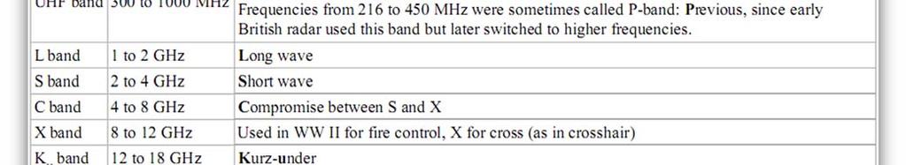
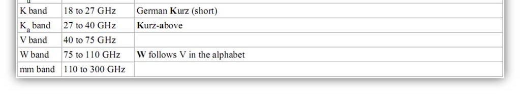
110 4.8.9 IEEE US 110

111 EU, NATO, US ECM frequency designations 111
112 4.9 Code division multiple access (CDMA) Code division multiple access (CDMA) is a channel access method utilized by various radio communication technologies. It should not be confused with the mobile phone standards called cdmaone and CDMA2000 (which are often referred to as simply "CDMA"), that use CDMA as their underlying channel access methods. One of the basic concepts in data communication is the idea of allowing several transmitters to send information simultaneously over a single communication channel. This allows several users to share a bandwidth of frequencies. This concept is called multiplexing. CDMA employs spread spectrum technology and a special coding scheme (where each transmitter is assigned a code) to allow multiple users to be multiplexed over the same physical channel. By contrast, time division multiple access (TDMA) divides access by time, while frequency division multiple access (FDMA) divides it by frequency. CDMA is a form of "spread spectrum" signaling, since the modulated coded signal has a much higher data bandwidth than the data being communicated. An analogy to the problem of multiple access is a room (channel) in which people wish to communicate with each other. To avoid confusion, people could take turns speaking (time division), speak at different pitches (frequency division), or speak in different directions (spatial division). In CDMA, they would speak different languages. People speaking the same language can understand each other, but not other people. Similarly, in radio CDMA, each group of users is given a shared code. Many codes occupy the same channel, but only users associated with a particular code can understand each other Uses One of the early applications for code division multiplexing predating, and distinct from cdmaone is in GPS. 112

113 The Qualcomm standard IS 95, marketed as cdmaone. The Qualcomm standard IS 2000, known as CDMA2000. This standard is used by several mobile phone companies, including the Globalstar satellite phone network. CDMA has been used in the OmniTRACS satellite system for transportation logistics Technical details CDMA is a spread spectrum multiple access technique. In CDMA a locally generated code runs at a much higher rate than the data to be transmitted. Data for transmission is simply logically XOR (exclusive OR) added with the faster code. The figure shows how spread spectrum signal is generated. The data signal with pulse duration of Tb is XOR added with the code signal with pulse duration of Tc. (Note: bandwidth is proportional to 1/T where T = bit time) Therefore, the bandwidth of the data signal is 1/Tb and the bandwidth of the spread spectrum signal is 1/Tc. Since Tc is much smaller than Tb, the bandwidth of the spread spectrum signal is much larger than the bandwidth of the original signal. Each user in a CDMA system uses a different code to modulate their signal. Choosing the codes used to modulate the signal is very important in the performance of CDMA systems. The best performance will occur when there is good separation between the signal of a desired user and 113
114 the signals of other users. The separation of the signals is made by correlating the received signal with the locally generated code of the desired user. If the signal matches the desired user's code then the correlation function will be high and the system can extract that signal. If the desired user's code has nothing in common with the signal the correlation should be as close to zero as possible (thus eliminating the signal); this is referred to as cross correlation. If the code is correlated with the signal at any time offset other than zero, the correlation should be as close to zero as possible. This is referred to as auto correlation and is used to reject multipath interference. In general, CDMA belongs to two basic categories: synchronous (orthogonal codes) and asynchronous (pseudorandom codes) Code Division Multiplexing (Synchronous CDMA) Synchronous CDMA exploits mathematical properties of orthogonality between vectors representing the data strings. For example, binary string "1011" is represented by the vector (1, 0, 1, 1). Vectors can be multiplied by taking their dot product, by summing the products of their respective components. If the dot product is zero, the two vectors are said to be orthogonal to each other. (Note: If u=(a,b) and v=(c,d), the dot product u.v = a*c + b*d) Some properties of the dot product help to understand how WCDMA works. If vectors a and b are orthogonal, then Each user in synchronous CDMA uses an orthogonal code to modulate their signal. An example of four mutually orthogonal digital signals is shown in the figure. Orthogonal codes have a cross correlation equal to zero; in other words, they do not interfere with each other. In the case of IS bit Walsh codes are used to encode the signal to separate different users. Since each of the 64 Walsh codes are orthogonal to one another, the signals are channelized into 64 orthogonal signals. The following example demonstrates how each users signal can be encoded and decoded. 114
115 4.10 WiMAX WiMAX, the Worldwide Interoperability for Microwave Access, is a telecommunications technology that provides for the wireless transmission of data in a variety of ways, ranging from point to point links to full mobile cellular type access. The technology provides the users with an idea of enjoying the broadband speed without the actual requirement of any wires or bulky network structures. The technology is based on the IEEE standard (also called Wireless MAN). The name "WiMAX" was created by the WiMAX Forum, which was formed in June 2001 to promote conformity and interoperability of the standard. The forum describes WiMAX as "a standards based technology enabling the delivery of last mile wireless broadband access as an alternative to cable and DSL" (and also to High Speed Packet Access). Currently, Pakistan has the largest fully functional Wimax network in the world. Wateen Telecom installed the network (with an initial rollout in seventeen cities) throughout Pakistan using Motorola hardware Definitions The terms "fixed WiMAX", "mobile WiMAX", "802.16d" and "802.16e" are frequently used incorrectly. Correct definitions are the following: is often called d, since that was the working party that developed the standard. It is also frequently referred to as "fixed WiMAX" since it has no support for mobility e 2005 is an amendment to and is often referred to in shortened form as e. It introduced support for mobility, amongst other things and is therefore also known as "mobile WiMAX" Uses The bandwidth and range of WiMAX make it suitable for the following potential applications: Connecting Wi Fi hotspots with other parts of the Internet. 115
116 Providing a wireless alternative to cable and DSL for "last mile" broadband access. Providing data and telecommunications services. Providing a source of Internet connectivity as part of a business continuity plan. That is, if a business has a fixed and a wireless Internet connection, especially from unrelated providers, they are unlikely to be affected by the same service outage. Providing portable connectivity Broadband access Many companies are closely examining WiMAX for last mile connectivity. The resulting competition may bring lower pricing for both home and business customers or bring broadband access to places where it has been economically unavailable. WiMAX access was used to assist with communications in Aceh, Indonesia, after the tsunami in December All communication infrastructures in the area, other than Ham Radio, was destroyed, making the survivors unable to communicate with people outside the disaster area and vice versa. WiMAX provided broadband access that helped regenerate communication to and from Aceh. In addition, WiMAX was used by Intel to assist the FCC and FEMA in their communications efforts in the areas affected by Hurricane Katrina Subscriber units WiMAX subscriber units are available in both indoor and outdoor versions from several manufacturers. Self install indoor units are convenient, but radio losses mean that the subscriber must be significantly closer to the WiMAX base station than with professionallyinstalled external units. As such, indoor installed units require a much higher infrastructure investment as well as operational cost (site lease, backhaul, maintenance) due to the high number of base stations required to cover a given area. Indoor units are comparable in size to a cable modem or DSL modem. Outdoor units are roughly the size of a laptop PC, and their installation is comparable to a residential satellite dish. 116
117 With the potential of mobile WiMAX, there is an increasing focus on portable units. This includes handsets (similar to cellular Smartphone s) and PC peripherals (PC Cards or USB dongles). In addition, there is much emphasis from operators on consumer electronics devices (game terminals, MP3 players and the like); it is notable this is more similar to Wi Fi than 3G cellular technologies. Current certified devices can be found at the WiMAX Forum web site. This is not a complete list of devices available as certified modules are embedded into laptops, MIDs (Mobile Internet Devices), and private labeled devices Mobile handset applications Some cellular companies are evaluating WiMAX as a means of increasing bandwidth for a variety of data intensive applications. Sprint Nextel announced in mid 2006 that it would invest about US$ 5 billion in a WiMAX technology build out over the next few years. Since that time Sprint has been dealt setbacks in defections of (Nextel) iden and 3G subscribers that have resulted in steep quarterly losses and led to a management shakeup with Dan Hesse as its new CEO. On May 7, 2008, Sprint, Clear wire, Google, Intel, Comcast, and Time Warner announced a pooling of 2.5 GHz spectrum and formation of a new company which will take the name Clear wire. The new company hopes to benefit from combined services offerings and network resources as a springboard past its competitors. The cable companies will provide media services to other partners while gaining access to the wireless network as an MVNO. Google will contribute Android handset device development and applications and will receive revenue share for advertising and other services they provide. Clear wire Sprint and current Clear wire gain a majority stock ownership in the new venture and ability to access between the new Clear wires and Sprint 3G networks. Some details remain unclear including how soon and in what form announced multi mode WiMAX and 3G EV DO devices will be available. This raises questions that arise for availability of competitive chips that require licensing of Qualcomm's IPR. 117
118 Backhaul/access network applications WiMAX is a possible replacement candidate for cellular phone technologies such as GSM and CDMA, or can be used as a layover to increase capacity. It has also been considered as a wireless backhaul technology for 2G, 3G, and 4G networks in both developed and developing nations."backhaul" for remote cellular operations is typically provided via satellite, and in urban areas via one or several T1 connections. WiMAX is mobile broadband and as such has much more substantial backhaul need. Therefore traditional backhaul solutions are not appropriate. Consequently the role of very high capacity wireless microwave point to point backhaul (200 or more Mbit/s with typically 1 ms or less delay) is on the rise. Also fiber backhaul is more appropriate. Deploying WiMAX in rural areas with limited or no internet backbone will be challenging as additional methods and hardware will be required to procure sufficient bandwidth from the nearest sources the difficulty being in proportion to the distance between the end user and the nearest sufficient internet backbone. Given the limited wired infrastructure in some developing countries, the costs to install a WiMAX station in conjunction with an existing cellular tower or even as a solitary hub are likely to be small in comparison to developing a wired solution. Areas of low population density and flat terrain are particularly suited to WiMAX and its range. For countries that have skipped wired infrastructure as a result of prohibitive costs and unsympathetic geography, WiMAX can enhance wireless infrastructure in an inexpensive, decentralized, deployment friendly and effective manner Technical information WiMAX is a term coined to describe standard, interoperable implementations of IEEE wireless networks, similar to the way the term Wi Fi is used for interoperable implementations of the IEEE Wireless LAN standard. However, WiMAX is very different from Wi Fi in the way it works. 118
119 MAC layer/data link layer In Wi Fi the media access controller (MAC) uses contention access all subscriber stations that wish to pass data through a wireless access point (AP) are competing for the AP's attention on a random interrupt basis. This can cause subscriber stations distant from the AP to be repeatedly interrupted by closer stations, greatly reducing their throughput. This makes services such as Voice over IP (VoIP) or IPTV, which depend on an essentially constant Quality of Service (QoS) depending on data rate and interruptibility, difficult to maintain for more than a few simultaneous users. In contrast, the MAC uses a scheduling algorithm for which the subscriber station needs to compete only once (for initial entry into the network). After that it is allocated an access slot by the base station. The time slot can enlarge and contract, but remains assigned to the subscriber station, which means that other subscribers cannot use it. In addition to being stable under overload and over subscription (unlike ), the scheduling algorithm can also be more bandwidth efficient. The scheduling algorithm also allows the base station to control QoS parameters by balancing the time slot assignments among the application needs of the subscriber stations Physical layer The original version of the standard on which WiMAX is based (IEEE ) specified a physical layer operating in the 10 to 66 GHz range a, updated in 2004 to , added specifications for the 2 to 11 GHz range was updated by e 2005 in 2005 and uses scalable orthogonal frequency division multiple access (SOFDMA) as opposed to the OFDM version with 256 sub carriers (of which 200 are used) in d. More advanced versions, including e, also bring Multiple Antenna Support through Multiple input multiple output communications (MIMO) See WiMAX MIMO. This brings potential benefits in terms of coverage, self installation, power consumption, frequency re use and bandwidth efficiency e also adds a capability for full mobility support. The WiMAX certification 119


120 allows vendors with d products to sell their equipment as WiMAX certified, thus ensuring a level of interoperability with other certified products, as long as they fit the same profile. Most commercial interest is in the d and.16e standards, since the lower frequencies used in these variants suffer less from inherent signal attenuation and therefore give improved range and in building penetration. Already today, a number of networks throughout the world are in commercial operation using certified WiMAX equipment compliant with the d standard Comparison with Wi Fi Comparisons and confusion between WiMAX and Wi Fi are frequent, possibly because both begin with the same two letters, are based upon IEEE standards beginning with "802.", and are related to wireless connectivity and Internet access. However, the two standards are aimed at different applications. WiMAX is a long range system, covering many kilometers that typically uses licensed spectrum (although it is possible to use unlicensed spectrum) to deliver a point to point connection to the Internet from an ISP to an end user. Different standards provide different types of access, from mobile (similar to a cell phone) to fixed (an 120
121 alternative to wired access, where the end user's wireless termination point is fixed in location.) Wi Fi is a shorter range system, typically tens of meters that uses unlicensed spectrum to provide access to a network. Typically Wi Fi is used by an end user to access their own network, which may or may not be connected to the Internet. If WiMAX provides services analogous to a cell phone, Wi Fi is similar to a cordless phone. It's important to note, however, that free community Wi Fi networks have shown that, with proper antennas, Wi Fi can have a very long range. WiMAX and Wi Fi have quite different Quality of Service (QoS) mechanisms. WiMAX uses a mechanism based on connections between the Base Station and the user device. Each connection is based on specific scheduling algorithms, which means that QoS parameters can be guaranteed for each flow. Wi Fi has introduced a QoS mechanism similar to fixed Ethernet, where packets can receive different priorities based on their tags. This means that QoS is relative between packets/flows, as opposed to guarantee. WiMAX is highly scalable from what are called "femto" scale remote stations to multisector 'maxi' scale base that handle complex tasks of management and mobile handoff functions and include MIMO AAS smart antenna subsystems Limitations A commonly held misconception is that WiMAX will deliver 70 Mbit/s over 50 kilometers. In reality, WiMAX can do one or the other operating over maximum range (50 km) increases bit error rate and thus must use a lower bitrates. Lowering the range allows a device to operate at higher bitrates. Typically, fixed WiMAX networks have a higher gain directional antenna installed near the client (customer) who results in greatly increased range and throughput. Mobile WiMAX networks are usually made of indoor "customer premises equipment" (CPE) such as desktop modems, laptops with integrated Mobile WiMAX or other Mobile WiMAX devices. Mobile WiMAX devices typically have an Omni directional antenna which is of lower gain compared to directional antennas but are more portable. In practice, this means that in a line of sight 121
122 environment with a portable Mobile WiMAX CPE, speeds of 10 Mbit/s at 10 km could be delivered. However, in urban environments they may not have line of sight and therefore users may only receive 10 Mbit/s over 2 km. In current deployments, throughputs are often closer to 2 Mbit/s symmetric at 10 km with fixed WiMAX and a high gain antenna. It is also important to consider that a throughput of 2 Mbit/s can mean 2 Mbit/s, symmetric simultaneously, 1 Mbit/s symmetric or some asymmetric mix (e.g. 0.5 Mbit/s downlink and 1.5 Mbit/s uplink or 1.5 Mbit/s downlink and 0.5 Mbit/s uplink), each of which required slightly different network equipment and configurations. Higher gain directional antennas can be used with a Mobile WiMAX network with range and throughput benefits but the obvious loss of practical mobility. Like most wireless systems, available bandwidth is shared between users in a given radio sector, so performance could deteriorate in the case of many active users in a single sector. In practice, many users will have a range of 2, 4, 6, 8, 10 or 12 Mbit/s services and additional radio cards will be added to the base station to increase the capacity as required. Because of this, various granular and distributed network architectures are being incorporated into WiMAX through independent development and within the j mobile multi hop relay (MMR) task group. This includes wireless mesh, grids, network remote station repeaters which can extend networks and connect to backhaul Standards The current WiMAX incarnation, Mobile WiMAX, is based upon IEEE Std e 2005, approved in December It is a supplement to the IEEE Std , and so the actual standard is as amended by e 2005 the specifications need to be read together to understand them. IEEE STD addresses only fixed systems. It replaced IEEE Standards , c 2002, and a IEEE e 2005 improves upon IEEE by: 122
123 Adding support for mobility (soft and hard handover between base stations). This is seen as one of the most important aspects of e 2005, and is the very basis of 'Mobile WiMAX'. Scaling of the Fast Fourier Transform (FFT) to the channel bandwidth in order to keep the carrier spacing constant across different channel bandwidths (typically 1.25 MHz, 5 MHz,10 MHz or 20 MHz). Constant carrier spacing results in higher spectrum efficiency in wide channels, and a cost reduction in narrow channels. Also known as Scalable OFDMA (SOFDMA). Other bands not multiples of 1.25 MHz are defined in the standard, but because the allowed FFT subcarrier numbers are only 128, 512, 1024 and 2048, other frequency bands will not have exactly the same carrier spacing, which might not be optimal for implementations. Improving NLOS coverage by utilizing advanced antenna diversity schemes, and hybrid Automatic Retransmission Request (HARQ) Improving capacity and coverage by introducing Adaptive Antenna Systems (AAS) and Multiple Input Multiple Output (MIMO) technology Increasing system gain by use of denser sub channelization, thereby improving indoor penetration Introducing high performance coding techniques such as Turbo Coding and Low Density Parity Check (LDPC), enhancing security and NLOS performance Introducing downlink sub channelization, allowing administrators to trade coverage for capacity or vice versa Enhanced Fast Fourier Transform algorithm can tolerate larger delay spreads, increasing resistance to multipath interference Adding an extra QoS class (enhanced real time Polling Service) more appropriate for VoIP applications. 123


124 4.11 Wireless LAN A wireless LAN or WLAN is a wireless local area network, which is the linking of two or more computers or devices without using wires. WLAN uses spread spectrum or OFDM modulation technology based on radio waves to enable communication between devices in a limited area, also known as the basic service set. This gives users the mobility to move around within a broad coverage area and still be connected to the network. For the home user, wireless has become popular due to ease of installation, and location freedom with the gaining popularity of laptops. Public businesses such as coffee shops or malls have begun to offer wireless access to their customers; some are even provided as a free service. Large wireless network projects are being put up in many major cities. Google is even providing a free service to Mountain View, California and has entered a bid to do the same for San Francisco. New York City has also begun a pilot program to cover all five boroughs of the city with wireless Internet access. 54 Mbit/s WLAN PCI Card (802.11g) An embedded Router Board History In 1970 University of Hawaii, under the leadership of Norman Abramson, developed the world s first computer communication network using low cost ham like radios, named ALOHA net. The 124
125 bi directional star topology of the system included seven computers deployed over four islands to communicate with the central computer on the Oahu Island without using phone lines. "In 1979, F.R. Gfeller and U. Bapst published a paper in the IEEE Proceedings reporting an experimental wireless local area network using diffused infrared communications. Shortly thereafter, in 1980, P. Ferrert reported on an experimental application of a single code spread spectrum radio for wireless terminal communications in the IEEE National Telecommunications Conference. In 1984, a comparison between Infrared and CDMA spread spectrum communications for wireless office information networks was published by Kaveh Pahlavan in IEEE Computer Networking Symposium which appeared later in the IEEE Communication Society Magazine. In May 1985, the efforts of Marcus led the FCC to announce experimental ISM bands for commercial application of spread spectrum technology. Later on, M. Kavehrad reported on an experimental wireless PBX system using code division multiple access. These efforts prompted significant industrial activities in the development of a new generation of wireless local area networks and it updated several old discussions in the portable and mobile radio industry. The first generation of wireless data modems was developed in the early 1980s by amateur radio operators, who commonly referred to this as packet radio. They added a voice band data communication modem, with data rates below 9600 bit/s, to an existing short distance radio system, typically in the two meter amateur band. The second generation of wireless modems was developed immediately after the FCC announcement in the experimental bands for nonmilitary use of the spread spectrum technology. These modems provided data rates on the order of hundreds of kbit/s. The third generation of wireless modem aimed at compatibility with the existing LANs with data rates on the order of Mbit/s. Several companies the third generation products with data rates above 1 Mbit/s and a couple of products already been announced [by the time of the first IEEE Workshop on Wireless LANs]." "The first of the IEEE Workshops on Wireless LAN was held in At that time early wireless LAN products had just appeared in the market and the IEEE committee had just started its activities to develop a standard for wireless LANs. The focus of that first workshop was 125
126 evaluation of the alternative technologies. The technology relatively mature, a variety of applications been identified and addressed and technologies that enable these applications well understood. Chip sets aimed at wireless LAN implementations and applications, a key enabling technology for rapid market growth, emerging in the market. Wireless LANs used in hospitals, stock exchanges, and other in building and campus settings for nomadic access, point to point LAN bridges, ad hoc networking, and even larger applications through internetworking. The IEEE standard and variants and alternatives, such as the wireless LAN interoperability forum and the European Hyper LAN specification had made rapid progress, and the unlicensed PCS \[ Unlicensed Personal Communications Services and the proposed SUPERNet, later on renamed as U NII, bands also presented new opportunities." On July 21, 1999, AirPort debuted at the Macworld Expo in New York City with Steve Jobs picking up an ibook supposedly to give the cameraman a better shot as he surfed the Web. Applause quickly built as people realized there were no wires. This was the first time Wireless LAN became publicly available at consumer pricing and easily available for home use. Before the release of the Airport, Wireless LAN was too expensive for consumer use and used exclusively in large corporate settings. Originally WLAN hardware was so expensive that it was only used as an alternative to cabled LAN in places where cabling was difficult or impossible. Early development included industryspecific solutions and proprietary protocols, but at the end of the 1990s these were replaced by standards, primarily the various versions of IEEE (Wi Fi). An alternative ATM like 5 GHz standardized technology, HiperLAN/2, has so far not succeeded in the market, and with the release of the faster 54 Mbit/s a (5 GHz) and g (2.4 GHz) standards, almost certainly never will. In November 2007, the Australian Commonwealth Scientific and Industrial Research Organization (CSIRO) won a legal battle in the US federal court of Texas against Buffalo Technology which found the US manufacturer had failed to pay royalties on a US WLAN patent CSIRO had filed in CSIRO are currently engaged in legal cases with computer companies 126
127 including Microsoft, Intel, Dell, Hewlett Packard and Netgear which argue that the patent is invalid and should negate any royalties paid to CSIRO for WLAN based products Benefits The popularity of wireless LANs is a testament primarily to their convenience, cost efficiency, and ease of integration with other networks and network components. The majority of computers sold to consumers today come pre equipped with all necessary wireless LAN technology. These are the benefits of wireless LANs: Convenience: The wireless nature of such networks allows users to access network resources from nearly any convenient location within their primary networking environment (home or office). With the increasing saturation of laptop style computers, this is particularly relevant. Mobility: With the emergence of public wireless networks, users can access the internet even outside their normal work environment. Most chain coffee shops, for example, offer their customers a wireless connection to the internet at little or no cost. Productivity: Users connected to a wireless network can maintain a nearly constant affiliation with their desired network as they move from place to place. For a business, this implies that an employee can potentially be more productive as his or her work can be accomplished from any convenient location. Deployment: Initial setup of an infrastructure based wireless network requires little more than a single access point. Wired networks, on the other hand, have the additional cost and complexity of actual physical cables being run to numerous locations (which can even be impossible for hard to reach locations within a building). Expandability: Wireless networks can serve a suddenly increased number of clients with the existing equipment. In a wired network, additional clients would require additional wiring. 127
128 Cost: Wireless networking hardware is at worst a modest increase from wired counterparts. This potentially increased cost is almost always more than outweighed by the savings in cost and labor associated to running physical cables Disadvantages Wireless LAN technology, while replete with the conveniences and advantages described above, has its share of downfalls. For a given networking situation, wireless LANs may not be desirable for a number of reasons. Most of these have to do with the inherent limitations of the technology. Security: Wireless LAN transceivers are designed to serve computers throughout a structure with uninterrupted service using radio frequencies. Because of space and cost, the antennas typically present on wireless networking cards in the end computers are generally relatively poor. In order to properly receive signals using such limited antennas throughout even a modest area, the wireless LAN transceiver utilizes a fairly considerable amount of power. What this means is that not only can the wireless packets be intercepted by a nearby adversary's poorly equipped computer, but more importantly, a user willing to spend a small amount of money on a good quality antenna can pick up packets at a remarkable distance; perhaps hundreds of times the radius as the typical user. In fact, there are even computer users dedicated to locating and sometimes even cracking into wireless networks, known as war drivers. On a wired network, any adversary would first have to overcome the physical limitation of tapping into the actual wires, but this is not an issue with wireless packets. To combat this consideration, wireless networks users usually choose to utilize various encryption technologies available such as Wi Fi Protected Access (WPA). Some of the older encryption methods, such as WEP are known to have weaknesses that a dedicated adversary can compromise. Range: The typical range of a common g network with standard equipment is on the order of tens of metres. While sufficient for a typical home, it will be insufficient in a larger structure. To obtain additional range, repeaters or additional access points will 128
129 have to be purchased. Costs for these items can add up quickly. Other technologies are in the development phase, however, which feature increased range, hoping to render this disadvantage irrelevant. Reliability: Like any radio frequency transmission, wireless networking signals are subject to a wide variety of interference, as well as complex propagation effects (such as multipath, or especially in this case Rician fading) that are beyond the control of the network administrator. One of the most insidious problems that can affect the stability and reliability of a wireless LAN is the microwave oven. In the case of typical networks, modulation is achieved by complicated forms of phase shift keying (PSK) or quadrature amplitude modulation (QAM), making interference and propagation effects all the more disturbing. As a result, important network resources such as servers are rarely connected wirelessly. Speed: The speed on most wireless networks (typically Mbit/s) is reasonably slow compared to the slowest common wired networks (100 Mbit/s up to several Gbit/s). There are also performance issues caused by TCP and its built in congestion avoidance. For most users, however, this observation is irrelevant since the speed bottleneck is not in the wireless routing but rather in the outside network connectivity itself. For example, the maximum ADSL throughput (usually 8 Mbit/s or less) offered by telecommunications companies to general purpose customers is already far slower than the slowest wireless network to which it is typically connected. That is to say, in most environments, a wireless network running at its slowest speed is still faster than the internet connection serving it in the first place. However, in specialized environments, higher throughput through a wired network might be necessary. Newer standards such as n are addressing this limitation and will support peak throughputs in the range of Mbit/s. Wireless LANs present a host of issues for network managers. Unauthorized access points, broadcasted SSIDs, unknown stations, and spoofed MAC addresses are just a few of the problems addressed in WLAN troubleshooting. Most network analysis vendors, such as 129
130 Network Instruments, Network General, and Fluke, offer WLAN troubleshooting tools or functionalities as part of their product line Architecture 1. Stations All components that can connect into a wireless medium in a network are referred to as stations. All stations are equipped with wireless network interface cards (WNICs). Wireless stations fall into one of two categories: access points, and clients. Access points (APs) are base stations for the wireless network. They transmit and receive radio frequencies for wireless enabled devices to communicate with. Wireless clients can be mobile devices such as laptops, personal digital assistants, IP phones, or fixed devices such as desktops and workstations that are equipped with a wireless network interface. 2. Basic service set The basic service set (BSS) is a set of all stations that can communicate with each other. There are two types of BSS: Independent BSS ( also referred to as IBSS ), and infrastructure BSS. Every BSS has an identification (ID) called the BSSID, which is the MAC address of the access point servicing the BSS. An independent BSS (IBSS) is an ad hoc network that contains no access points, which means they can not connect to any other basic service set. An infrastructure BSS can communicate with other stations not in the same basic service set by communicating through access points. 3. Extended service set An extended service set (ESS) is a set of connected BSSes. Access points in an ESS are connected by a distribution system. Each ESS has an ID called the SSID which is a 32 byte (maximum) character string. For example, "Linksys" is the default SSID for Linksys routers. 130
. There is no base and no one gives permission to talk.")
131 4. Distribution system A distribution system (DS) connects access points in an extended service set. The concept of a DS can be to increase network coverage through roaming between cells Types of wireless LANs An ad hoc network is a network where stations communicate only peer to peer (P2P). There is no base and no one gives permission to talk. This is accomplished using the Independent Basic Service Set (IBSS). A peer to peer (P2P) allows wireless devices to directly communicate with each other. Wireless devices within range of each other can discover and communicate directly without involving central access points. This method is typically used by two computers so that they can connect to each other to form a network. If a signal strength meter is used in this situation, it may not read the strength accurately and can be misleading, because it registers the strength of the strongest signal, which may be the closest computer specs define the physical layer (PHY) and MAC (Media Access Control) layers. However, unlike most other IEEE specs, includes three alternative PHY standards: diffuse infrared operating at 1 Mbit/s in; frequency hopping spread spectrum operating at 1 Mbit/s or 2 Mbit/s; and direct sequence spread spectrum operating at 1 Mbit/s or 2 Mbit/s. A single MAC standard is based on CSMA/CA (Carrier Sense Multiple Access with Collision Avoidance). The specification includes provisions designed to minimize collisions. Because two mobile units may both be in range of a common access point, but not in range of each other. The has two basic modes of operation: Ad hoc mode enables peer to peer transmission between mobile units. Infrastructure mode in which mobile units communicate through an access point that serves as a bridge to a wired network infrastructure is the more common wireless LAN application the one being covered. Since wireless communication uses a more open medium for communication in comparison to wired LANs, the designers also included a shared key encryption mechanism, called wired equivalent privacy (WEP), or Wi Fi Protected Access, (WPA, WPA2) to secure wireless computer networks. 131

132 Bridge A bridge can be used to connect networks, typically of different types. A wireless Ethernet bridge allows the connection of devices on a wired Ethernet network to a wireless network. The bridge acts as the connection point to the Wireless LAN Wireless distribution system When it is difficult to connect all of the access points in a network by wires, it is also possible to put up access points as repeaters Roaming There are 2 definitions for roaming in WLAN: Internal Roaming (1): The Mobile Station (MS) moves from one access point (AP) to another AP within a home network because the signal strength is too weak. An authentication server (RADIUS) assumes the re authentication of MS via 802.1x (e.g. with PEAP). The billing of QoS is in the home network. External Roaming (2): The MS(client) moves into a WLAN of an another Wireless Service Provider (WSP) and takes their services (Hotspot). The user can independently of his home network use another foreign network, if this is open for visitors. There must be special authentication and billing systems for mobile services in a foreign network. Roaming between Wireless Local Area Networks 132


133 A diagram showing a WI FI network 133
3.1. Historical Overview. Citizens` Band Radio Cordless Telephones Improved Mobile Telephone Service (IMTS)
") III. Cellular Radio Historical Overview Introduction to the Advanced Mobile Phone System (AMPS) AMPS Control System Security and Privacy Cellular Telephone Specifications and Operation 3.1. Historical
III. Cellular Radio Historical Overview Introduction to the Advanced Mobile Phone System (AMPS) AMPS Control System Security and Privacy Cellular Telephone Specifications and Operation 3.1. Historical
ECE 476/ECE 501C/CS Wireless Communication Systems Winter Lecture 9: Multiple Access, GSM, and IS-95
 ECE 476/ECE 501C/CS 513 - Wireless Communication Systems Winter 2003 Lecture 9: Multiple Access, GSM, and IS-95 Outline: Two other important issues related to multiple access space division with smart
CS 218 Fall 2003 October 23, 2003
 CS 218 Fall 2003 October 23, 2003 Cellular Wireless Networks AMPS (Analog) D-AMPS (TDMA) GSM CDMA Reference: Tanenbaum Chpt 2 (pg 153-169) Cellular Wireless Network Evolution First Generation: Analog AMPS:
Access Methods and Spectral Efficiency
 Access Methods and Spectral Efficiency Yousef Dama An-Najah National University Mobile Communications Access methods SDMA/FDMA/TDMA SDMA (Space Division Multiple Access) segment space into sectors, use
MOBILE COMPUTING 4/8/18. Basic Call. Public Switched Telephone Network - PSTN. CSE 40814/60814 Spring Transit. switch. Transit. Transit.
 MOBILE COMPUTING CSE 40814/60814 Spring 2018 Public Switched Telephone Network - PSTN Transit switch Transit switch Long distance network Transit switch Local switch Outgoing call Incoming call Local switch
Multiplexing Module W.tra.2
 Multiplexing Module W.tra.2 Dr.M.Y.Wu@CSE Shanghai Jiaotong University Shanghai, China Dr.W.Shu@ECE University of New Mexico Albuquerque, NM, USA 1 Multiplexing W.tra.2-2 Multiplexing shared medium at
Wireless and Mobile Network Architecture. Outline. Introduction. Cont. Chapter 1: Introduction
 Wireless and Mobile Network Architecture Chapter 1: Introduction Prof. Yuh-Shyan Chen Department of Computer Science and Information Engineering National Taipei University Sep. 2006 Outline Introduction
Wireless and Mobile Network Architecture
 Wireless and Mobile Network Architecture Chapter 1: Introduction Prof. Yuh-Shyan Chen Department of Computer Science and Information Engineering National Taipei University Sep. 2006 1 Outline Introduction
Chapter 14. Cellular Wireless Networks
 Chapter 14 Cellular Wireless Networks Evolu&on of Wireless Communica&ons 1901 Marconi: Trans-Atlantic wireless transmission 1906 Fessenden: first radio broadcast (AM) 1921 Detroit Police Dept wireless
CDMA Principle and Measurement
 CDMA Principle and Measurement Concepts of CDMA CDMA Key Technologies CDMA Air Interface CDMA Measurement Basic Agilent Restricted Page 1 Cellular Access Methods Power Time Power Time FDMA Frequency Power
Chapter 11. Mobile Telephony History. Mikael Olofsson 2004
 Chapter 11 Mobile Telephony Mikael Olofsson 2004 Devices for wire-less two-way communication between individual users have been around for several tens of years, and they are usually called walkie-talkies.
GTBIT ECE Department Wireless Communication
 Q-1 What is Simulcast Paging system? Ans-1 A Simulcast Paging system refers to a system where coverage is continuous over a geographic area serviced by more than one paging transmitter. In this type of
Personal Communication System
 Personal Communication System Differences Between Cellular Systems and PCS IS-136 (TDMA) PCS GSM i-mode mobile communication IS-95 CDMA PCS Comparison of Modulation Schemes Data Communication with PCS
Data and Computer Communications. Chapter 10 Cellular Wireless Networks
 Data and Computer Communications Chapter 10 Cellular Wireless Networks Cellular Wireless Networks 5 PSTN Switch Mobile Telecomm Switching Office (MTSO) 3 4 2 1 Base Station 0 2016-08-30 2 Cellular Wireless
Difference Between. 1. Old connection is broken before a new connection is activated.
 Difference Between Hard handoff Soft handoff 1. Old connection is broken before a new connection is activated. 1. New connection is activated before the old is broken. 2. "break before make" connection
A Glimps at Cellular Mobile Radio Communications. Dr. Erhan A. İnce
 A Glimps at Cellular Mobile Radio Communications Dr. Erhan A. İnce 28.03.2012 CELLULAR Cellular refers to communications systems that divide a geographic region into sections, called cells. The purpose
UNIT- 3. Introduction. The cellular advantage. Cellular hierarchy
 UNIT- 3 Introduction Capacity expansion techniques include the splitting or sectoring of cells and the overlay of smaller cell clusters over larger clusters as demand and technology increases. The cellular
10EC81-Wireless Communication UNIT-6
 UNIT-6 The first form of CDMA to be implemented is IS-95, specified a dual mode of operation in the 800Mhz cellular band for both AMPS and CDMA. IS-95 standard describes the structure of wideband 1.25Mhz
RADIO LINK ASPECT OF GSM
 RADIO LINK ASPECT OF GSM The GSM spectral allocation is 25 MHz for base transmission (935 960 MHz) and 25 MHz for mobile transmission With each 200 KHz bandwidth, total number of channel provided is 125
Page 1. Problems with 1G Systems. Wireless Wide Area Networks (WWANs) EEC173B/ECS152C, Spring Cellular Wireless Network
 EEC173B/ECS152C, Spring Cellular Wireless Network") EEC173B/ECS152C, Spring 2009 Wireless Wide Area Networks (WWANs) Cellular Wireless Network Architecture and Protocols Applying concepts learned in first two weeks: Frequency planning, channel allocation
EEC173B/ECS152C, Spring 2009 Wireless Wide Area Networks (WWANs) Cellular Wireless Network Architecture and Protocols Applying concepts learned in first two weeks: Frequency planning, channel allocation
3.6. Cell-Site Equipment. Traffic and Cell Splitting Microcells, Picocelles and Repeaters
 3.6. Cell-Site Equipment Traffic and Cell Splitting Microcells, Picocelles and Repeaters The radio transmitting equipment at the cell site operates at considerably higher power than do the mobile phones,
Ammar Abu-Hudrouss Islamic University Gaza
 Wireless Communications n Ammar Abu-Hudrouss Islamic University Gaza ١ Course Syllabus References 1. A. Molisch,, Wiely IEEE, 2nd Edition, 2011. 2. Rappaport, p : Principles and Practice, Prentice Hall
CMC VIDYA SAGAR P. UNIT IV FREQUENCY MANAGEMENT AND CHANNEL ASSIGNMENT Numbering and grouping, Setup access and paging
 UNIT IV FREQUENCY MANAGEMENT AND CHANNEL ASSIGNMENT Numbering and grouping, Setup access and paging channels, Channel assignments to cell sites and mobile units, Channel sharing and barrowing, sectorization,
Introduction to IS-95 CDMA p. 1 What is CDMA p. 1 History of CDMA p. 2 Forms of CDMA p MHz CDMA p MHz CDMA (PCS) p. 6 CDMA Parts p.
 p. 6 CDMA Parts p.") Introduction to IS-95 CDMA p. 1 What is CDMA p. 1 History of CDMA p. 2 Forms of CDMA p. 3 800 MHz CDMA p. 6 1900 MHz CDMA (PCS) p. 6 CDMA Parts p. 7 Mobile Station p. 8 Base Station Subsystem (BSS) p.
Introduction to IS-95 CDMA p. 1 What is CDMA p. 1 History of CDMA p. 2 Forms of CDMA p. 3 800 MHz CDMA p. 6 1900 MHz CDMA (PCS) p. 6 CDMA Parts p. 7 Mobile Station p. 8 Base Station Subsystem (BSS) p.
CS6956: Wireless and Mobile Networks Lecture Notes: 3/23/2015
 CS6956: Wireless and Mobile Networks Lecture Notes: 3/23/2015 GSM Global System for Mobile Communications (reference From GSM to LET by Martin Sauter) There were ~3 billion GSM users in 2010. GSM Voice
Chapter 1 Introduction to Mobile Computing (16 M)
") Chapter 1 Introduction to Mobile Computing (16 M) 1.1 Introduction to Mobile Computing- Mobile Computing Functions, Mobile Computing Devices, Mobile Computing Architecture, Evolution of Wireless Technology.
Chapter 1 Introduction to Mobile Computing (16 M) 1.1 Introduction to Mobile Computing- Mobile Computing Functions, Mobile Computing Devices, Mobile Computing Architecture, Evolution of Wireless Technology.
The Cellular Concept. History of Communication. Frequency Planning. Coverage & Capacity
 The Cellular Concept History of Communication Frequency Planning Coverage & Capacity Engr. Mian Shahzad Iqbal Lecturer Department of Telecommunication Engineering Before GSM: Mobile Telephony Mile stones
Data and Computer Communications
 Data and Computer Communications Chapter 14 Cellular Wireless Networks Eighth Edition by William Stallings Cellular Wireless Networks key technology for mobiles, wireless nets etc developed to increase
APPLICATION PROGRAMMING: MOBILE COMPUTING [ INEA00112W ] Marek Piasecki PhD Wireless Telecommunication
![APPLICATION PROGRAMMING: MOBILE COMPUTING [ INEA00112W ] Marek Piasecki PhD Wireless Telecommunication](/thumbs/82/86735605.jpg "APPLICATION PROGRAMMING: MOBILE COMPUTING [ INEA00112W ] Marek Piasecki PhD Wireless Telecommunication") APPLICATION PROGRAMMING: MOBILE COMPUTING [ INEA00112W ] Marek Piasecki PhD Wireless Telecommunication (W6/2013) What is Wireless Communication? Transmitting/receiving voice and data using electromagnetic
APPLICATION PROGRAMMING: MOBILE COMPUTING [ INEA00112W ] Marek Piasecki PhD Wireless Telecommunication (W6/2013) What is Wireless Communication? Transmitting/receiving voice and data using electromagnetic
Wireless Cellular Networks. Base Station - Mobile Network
 Wireless Cellular Networks introduction frequency reuse channel assignment strategies techniques to increase capacity handoff cellular standards 1 Base Station - Mobile Network RCC RVC FVC FCC Forward
MAHARASHTRA STATE BOARD OF TECHNICAL EDUCATION (Autonomous) (ISO/IEC Certified)
 (ISO/IEC Certified)") WINTER 16 EXAMINATION Model Answer Subject Code: 17657 Important Instructions to examiners: 1) The answers should be examined by key words and not as word-to-word as given in the model answer scheme. 2)
WINTER 16 EXAMINATION Model Answer Subject Code: 17657 Important Instructions to examiners: 1) The answers should be examined by key words and not as word-to-word as given in the model answer scheme. 2)
2.4 OPERATION OF CELLULAR SYSTEMS
 INTRODUCTION TO CELLULAR SYSTEMS 41 a no-traffic spot in a city. In this case, no automotive ignition noise is involved, and no cochannel operation is in the proximity of the idle-channel receiver. We
3G TECHNOLOGY WHICH CAN PROVIDE AUGMENTED DATA TRANSFER RATES FOR GSM STANDARTS AND THE MODULATION TECHNIQUES
 3G TECHNOLOGY WHICH CAN PROVIDE AUGMENTED DATA TRANSFER RATES FOR GSM STANDARTS AND THE MODULATION TECHNIQUES Mustafa ALKAN Ejder ORUÇ Nur ERZEN Özgür GENÇ malkan@tk.gov.tr eoruc@tk.gov.tr nerzen@tk.gov.tr
Introduction to Wireless and Mobile Networking. Hung-Yu Wei g National Taiwan University
 Introduction to Wireless and Mobile Networking Lecture 3: Multiplexing, Multiple Access, and Frequency Reuse Hung-Yu Wei g National Taiwan University Multiplexing/Multiple Access Multiplexing Multiplexing
EE 577: Wireless and Personal Communications
 EE 577: Wireless and Personal Communications Dr. Salam A. Zummo Lecture 1: Introduction 1 Common Applications of Wireless Systems AM/FM Radio Broadcast VHF and UHF TV Broadcast Cordless Phones (e.g., DECT)
Chapter 1 INTRODUCTION
 Chapter 1 INTRODUCTION 1 The History of Mobile Radio Communication (1/3) 1880: Hertz Initial demonstration of practical radio communication 1897: Marconi Radio transmission to a tugboat over an 18 mi path
CDMA is used to a limited extent on the 800-MHz band, but is much more common in the 1900-MHz PCS band. It uses code-division multiple access by
 IS-95 CDMA PCS CDMA Frequency Use CDMA Channels Forward Channel Reverse Channel Voice Coding Mobile Power Control Rake Receivers and Soft handoffs CDMA Security CDMA is used to a limited extent on the
CDMA - QUESTIONS & ANSWERS
 CDMA - QUESTIONS & ANSWERS http://www.tutorialspoint.com/cdma/questions_and_answers.htm Copyright tutorialspoint.com 1. What is CDMA? CDMA stands for Code Division Multiple Access. It is a wireless technology
ECE 476/ECE 501C/CS Wireless Communication Systems Winter Lecture 3: Cellular Fundamentals
 ECE 476/ECE 501C/CS 513 - Wireless Communication Systems Winter 2004 Lecture 3: Cellular Fundamentals Chapter 3 - The Cellular Concept - System Design Fundamentals I. Introduction Goals of a Cellular System
Band Class Specification for cdma2000 Spread Spectrum Systems
 GPP C.S00-B Version.0 Date: August, 00 Band Class Specification for cdma000 Spread Spectrum Systems Revision B COPYRIGHT GPP and its Organizational Partners claim copyright in this document and individual
Medium Access Control. Wireless Networks: Guevara Noubir. Slides adapted from Mobile Communications by J. Schiller
 Wireless Networks: Medium Access Control Guevara Noubir Slides adapted from Mobile Communications by J. Schiller S200, COM3525 Wireless Networks Lecture 4, Motivation Can we apply media access methods
Section A : example questions
 2G1723 GSM Network and Services The exam will consist of two sections: section A (20p) and section B (8p). Section A consist of 20 multiple-choice questions (1p each), where exactly one answer is correct.
Multiple Access Schemes
 Multiple Access Schemes Dr Yousef Dama Faculty of Engineering and Information Technology An-Najah National University 2016-2017 Why Multiple access schemes Multiple access schemes are used to allow many
SLIDE #2.1. MOBILE COMPUTING NIT Agartala, Dept of CSE Jan-May,2012. ALAK ROY. Assistant Professor Dept. of CSE NIT Agartala
 Mobile Cellular Systems SLIDE #2.1 MOBILE COMPUTING NIT Agartala, Dept of CSE Jan-May,2012 ALAK ROY. Assistant Professor Dept. of CSE NIT Agartala Email-alakroy.nerist@gmail.com What we will learn in this
Band Class Specification for cdma2000 Spread Spectrum Systems
 GPP C.S00 Version.0 Date: February, 00 Band Class Specification for cdma000 Spread Spectrum Systems Revision 0 COPYRIGHT GPP and its Organizational Partners claim copyright in this document and individual
GLOBAL SYSTEM FOR MOBILE COMMUNICATION. ARFCNS, CHANNELS ETI 2511 Thursday, March 30, 2017
 GLOBAL SYSTEM FOR MOBILE COMMUNICATION ARFCNS, CHANNELS ETI 2511 Thursday, March 30, 2017 1 GLOBAL GSM FREQUENCY USAGE 2 EXAMPLE: GSM FREQUENCY ALLOCATION Generally, countries with large land mass would
SEN366 (SEN374) (Introduction to) Computer Networks
 (Introduction to) Computer Networks") SEN366 (SEN374) (Introduction to) Computer Networks Prof. Dr. Hasan Hüseyin BALIK (8 th Week) Cellular Wireless Network 8.Outline Principles of Cellular Networks Cellular Network Generations LTE-Advanced
SEN366 (SEN374) (Introduction to) Computer Networks Prof. Dr. Hasan Hüseyin BALIK (8 th Week) Cellular Wireless Network 8.Outline Principles of Cellular Networks Cellular Network Generations LTE-Advanced
UCS-805 MOBILE COMPUTING NIT Agartala, Dept of CSE Jan-May,2011
 Location Management for Mobile Cellular Systems SLIDE #3 UCS-805 MOBILE COMPUTING NIT Agartala, Dept of CSE Jan-May,2011 ALAK ROY. Assistant Professor Dept. of CSE NIT Agartala Email-alakroy.nerist@gmail.com
WIRELESS TERMINAL EQUIPMENT. ETI TELECOMMUNICATIONS Monday, 10 October 2016
 WIRELESS TERMINAL EQUIPMENT ETI2506 - TELECOMMUNICATIONS Monday, 10 October 2016 1 CLASSIFICATION OF MOBILE RADIO TRANSMISSION 1. Simplex radio systems utilize simplex channels i.e., the communication
Mobile Communication and Mobile Computing
 Department of Computer Science Institute for System Architecture, Chair for Computer Networks Mobile Communication and Mobile Computing Prof. Dr. Alexander Schill http://www.rn.inf.tu-dresden.de Structure
Public Safety Radio Frequency Spectrum: A Comparison of Multiple Access Techniques
 Saving Lives and Property Through Improved Interoperability Public Safety Radio Frequency Spectrum: A Comparison of Multiple Access Techniques FINAL November 2001 Table of Contents Page 1. Introduction...
Chapter 1 Acknowledgment:
 Chapter 1 Acknowledgment: This material is based on the slides formatted by Dr Sunilkumar S. Manvi and Dr Mahabaleshwar S. Kakkasageri, the authors of the textbook: Wireless and Mobile Networks, concepts
Mohammad Hossein Manshaei 1393
 Mohammad Hossein Manshaei manshaei@gmail.com 1393 GSM 2 GSM Architecture Frequency Band and Channels Frames in GSM Interfaces, Planes, and Layers of GSM Handoff Short Message Service (SMS) 3 subscribers
Lecture #6 Basic Concepts of Cellular Transmission (p3)
") November 2014 Integrated Technical Education Cluster At AlAmeeria E-716-A Mobile Communications Systems Lecture #6 Basic Concepts of Cellular Transmission (p3) Instructor: Dr. Ahmad El-Banna Agenda Duplexing
November 2014 Integrated Technical Education Cluster At AlAmeeria E-716-A Mobile Communications Systems Lecture #6 Basic Concepts of Cellular Transmission (p3) Instructor: Dr. Ahmad El-Banna Agenda Duplexing
ECE 5325/6325: Wireless Communication Systems Lecture Notes, Spring 2013
 ECE 5325/6325: Wireless Communication Systems Lecture Notes, Spring 2013 Lecture 1 Today: (1) Syllabus, (2) Cellular Systems Intro, (3) Power and Path Loss Readings: Molisch Chapters 1, 2. For Thursday:
Mobile & Wireless Networking. Lecture 4: Cellular Concepts & Dealing with Mobility. [Reader, Part 3 & 4]
![Mobile & Wireless Networking. Lecture 4: Cellular Concepts & Dealing with Mobility. [Reader, Part 3 & 4]](/thumbs/85/91945930.jpg "Mobile & Wireless Networking. Lecture 4: Cellular Concepts & Dealing with Mobility. [Reader, Part 3 & 4]") 192620010 Mobile & Wireless Networking Lecture 4: Cellular Concepts & Dealing with Mobility [Reader, Part 3 & 4] Geert Heijenk Outline of Lecture 4 Cellular Concepts q Introduction q Cell layout q Interference
192620010 Mobile & Wireless Networking Lecture 4: Cellular Concepts & Dealing with Mobility [Reader, Part 3 & 4] Geert Heijenk Outline of Lecture 4 Cellular Concepts q Introduction q Cell layout q Interference
CHAPTER 19 CELLULAR TELEPHONE CONCEPTS # DEFINITION TERMS
 CHAPTER 19 CELLULAR TELEPHONE CONCEPTS # DEFINITION TERMS 1) The term for mobile telephone services which began in 1940s and are sometimes called Manual telephone systems. Mobile Telephone Manual System
CDMA Key Technology. ZTE Corporation CDMA Division
 CDMA Key Technology ZTE Corporation CDMA Division CDMA Key Technology Spread Spectrum Communication Code Division Multiple Access Power Control Diversity Soft Handoff Rake Receiver Variable Rate Vocoder
CS 6956 Wireless & Mobile Networks April 1 st 2015
 CS 6956 Wireless & Mobile Networks April 1 st 2015 The SIM Card Certain phones contain SIM lock and thus work only with the SIM card of a certain operator. However, this is not a GSM restriction introduced
Chapter 2 Overview. Duplexing, Multiple Access - 1 -
 Chapter 2 Overview Part 1 (2 weeks ago) Digital Transmission System Frequencies, Spectrum Allocation Radio Propagation and Radio Channels Part 2 (last week) Modulation, Coding, Error Correction Part 3
Cellular systems 02/10/06
 Cellular systems 02/10/06 Cellular systems Implements space division multiplex: base station covers a certain transmission area (cell) Mobile stations communicate only via the base station Cell sizes from
Chapter 2: Global System for Mobile Communication
 Chapter 2: Global System for Mobile Communication (22 Marks) Introduction- GSM services and features, GSM architecture, GSM channel types, Example of GSM Call: GSM to PSTN call, PSTN to GSM call. GSM frame
Mobile Computing. Chapter 3: Medium Access Control
 Mobile Computing Chapter 3: Medium Access Control Prof. Sang-Jo Yoo Contents Motivation Access methods SDMA/FDMA/TDMA Aloha Other access methods Access method CDMA 2 1. Motivation Can we apply media access
GSM and WCDMA RADIO SYSTEMS ETIN15. Lecture no: Ove Edfors, Department of Electrical and Information Technology
 RADIO SYSTEMS ETIN15 Lecture no: 11 GSM and WCDMA Ove Edfors, Department of Electrical and Information Technology Ove.Edfors@eit.lth.se 2015-05-12 Ove Edfors - ETIN15 1 Contents (Brief) history of mobile
Page 1. Overview : Wireless Networks Lecture 9: OFDM, WiMAX, LTE
 Overview 18-759: Wireless Networks Lecture 9: OFDM, WiMAX, LTE Dina Papagiannaki & Peter Steenkiste Departments of Computer Science and Electrical and Computer Engineering Spring Semester 2009 http://www.cs.cmu.edu/~prs/wireless09/
CHAPTER 2. Instructor: Mr. Abhijit Parmar Course: Mobile Computing and Wireless Communication ( )
") CHAPTER 2 Instructor: Mr. Abhijit Parmar Course: Mobile Computing and Wireless Communication (2170710) Syllabus Chapter-2.1 Cellular Wireless Networks 2.1.1 Principles of Cellular Networks Underlying technology
CHAPTER 2 Instructor: Mr. Abhijit Parmar Course: Mobile Computing and Wireless Communication (2170710) Syllabus Chapter-2.1 Cellular Wireless Networks 2.1.1 Principles of Cellular Networks Underlying technology
Dynamic Dual Mode for ASTRO 25 Systems:
 SOLUTION PAPER Dynamic Dual Mode for ASTRO 25 Systems: Greater Capacity and Seamless Interoperability with Project 25 Phase 1 New technology promises to boost the capacity of your radio communications
Data and Computer Communications. Tenth Edition by William Stallings
 Data and Computer Communications Tenth Edition by William Stallings Data and Computer Communications, Tenth Edition by William Stallings, (c) Pearson Education - 2013 CHAPTER 10 Cellular Wireless Network
Roger Kane Managing Director, Vicom Australia
 Understanding and testing of DMR standard Roger Kane Managing Director, Vicom Australia @CommsConnectAus#comms2014 Presentation Title: Understanding and Testing DMR Speaker: Roger Kane @CommsConnectAus
Chapter 7. Multiple Division Techniques
 Chapter 7 Multiple Division Techniques 1 Outline Frequency Division Multiple Access (FDMA) Division Multiple Access (TDMA) Code Division Multiple Access (CDMA) Comparison of FDMA, TDMA, and CDMA Walsh
Mobile Communication Systems. Part 7- Multiplexing
 Mobile Communication Systems Part 7- Multiplexing Professor Z Ghassemlooy Faculty of Engineering and Environment University of Northumbria U.K. http://soe.ac.uk/ocr Contents Multiple Access Multiplexing
Chapter 8: GSM & CDAMA Systems
 Chapter 8: GSM & CDAMA Systems Global System for Mobile Communication (GSM) Second Generation (Digital) Cellular System Operated in 900 MHz band GSM is also operated in 1800 MHz band and this version of
Wireless systems. includes issues of
 Wireless systems includes issues of hardware processors, storage, peripherals, networks,... representation of information, analog vs. digital, bits & bytes software applications, operating system organization
CSC344 Wireless and Mobile Computing. Department of Computer Science COMSATS Institute of Information Technology
 CSC344 Wireless and Mobile Computing Department of Computer Science COMSATS Institute of Information Technology Wireless Cellular Networks: 2.5G and 3G 2.5G Data services over 2G networks GSM: High-speed
Chapter 3 : Media Access. Mobile Communications. Collision avoidance, MACA
 Mobile Communications Chapter 3 : Media Access Motivation Collision avoidance, MACA SDMA, FDMA, TDMA Polling Aloha CDMA Reservation schemes SAMA Comparison Prof. Dr.-Ing. Jochen Schiller, http://www.jochenschiller.de/
Week 2. Topics in Wireless Systems EE584-F 03 9/9/2003. Copyright 2003 Stevens Institute of Technology - All rights reserved
 Week Topics in Wireless Systems 43 0 th Generation Wireless Systems Mobile Telephone Service Few, high-power, long-range basestations -> No sharing of spectrum -> few users -> expensive 44 Cellular Systems
Course Overview. AMPS: History
 Course Overview Introduction and History Data in Wireless Cellular Systems: AMPS and CDPD Data in Wireless Local Area Networks Internet Protocols Routing and Ad-Hoc Networks TCP over Wireless Link Services
RADIO SYSTEMS ETIN15. Lecture no: GSM and WCDMA. Ove Edfors, Department of Electrical and Information Technology
 RADIO SYSTEMS ETIN15 Lecture no: 11 GSM and WCDMA Ove Edfors, Department of Electrical and Information Technology Ove.Edfors@eit.lth.se 1 Contents (Brief) history of mobile telephony Global System for
Unit 0: Brief history, present and future of the wireless communications
 Unit 0: Brief history, present and future of the wireless communications Wireless communications course Ronal D. Montoya M. http://tableroalparque.weebly.com/radiocomunicaciones.html ronalmontoya5310@correo.itm.edu.co
Medium Access Control
 CMPE 477 Wireless and Mobile Networks Medium Access Control Motivation for Wireless MAC SDMA FDMA TDMA CDMA Comparisons CMPE 477 Motivation Can we apply media access methods from fixed networks? Example
Mobile Radio Systems (Wireless Communications)
") Mobile Radio Systems (Wireless Communications) Klaus Witrisal witrisal@tugraz.at Signal Processing and Speech Communication Lab, TU Graz Lecture 1 WS2015/16 (6 October 2016) Key Topics of this Lecture
Mobile Radio Systems (Wireless Communications) Klaus Witrisal witrisal@tugraz.at Signal Processing and Speech Communication Lab, TU Graz Lecture 1 WS2015/16 (6 October 2016) Key Topics of this Lecture
Unit-1 The Cellular Concept
 Unit-1 The Cellular Concept 1.1 Introduction to Cellular Systems Solves the problem of spectral congestion and user capacity. Offer very high capacity in a limited spectrum without major technological
Multiple Access System
 Multiple Access System TDMA and FDMA require a degree of coordination among users: FDMA users cannot transmit on the same frequency and TDMA users can transmit on the same frequency but not at the same
Chapter 3: Cellular concept
 Chapter 3: Cellular concept Introduction to cellular concept: The cellular concept was a major breakthrough in solving the problem of spectral congestion and user capacity. It offered very high capacity
LECTURE 12. Deployment and Traffic Engineering
 1 LECTURE 12 Deployment and Traffic Engineering Cellular Concept 2 Proposed by Bell Labs in 1971 Geographic Service divided into smaller cells Neighboring cells do not use same set of frequencies to prevent
Transcoding free voice transmission in GSM and UMTS networks
 Transcoding free voice transmission in GSM and UMTS networks Sara Stančin, Grega Jakus, Sašo Tomažič University of Ljubljana, Faculty of Electrical Engineering Abstract - Transcoding refers to the conversion
Wireless WANS and MANS. Chapter 3
 Wireless WANS and MANS Chapter 3 Cellular Network Concept Use multiple low-power transmitters (100 W or less) Areas divided into cells Each served by its own antenna Served by base station consisting of
Wireless CommuniCation. unit 5
 Wireless CommuniCation unit 5 V. ADVANCED TRANSCEIVER SCHEMES Spread Spectrum Systems- Cellular Code Division Multiple Access Systems- Principle, Power control, Effects of multipath propagation on Code
Page 1. What is a Survey? : Wireless Networks Lecture 8: Cellular Networks. Deliverables. Surveys. Cell splitting.
 What is a Survey? 18-759: Wireless Networks Lecture 8: Cellular Networks Dina Papagiannaki & Peter Steenkiste Departments of Computer Science and Electrical and Computer Engineering Spring Semester 2009
The Public Switched Telephone Network (PSTN)
") The Public Switched Telephone Network (PSTN) Importance of Telephony Official name: the Public Switched Telephone Network New technologies revolutionizing plain old telephone service (POTS) More options
The Public Switched Telephone Network (PSTN) Importance of Telephony Official name: the Public Switched Telephone Network New technologies revolutionizing plain old telephone service (POTS) More options
Chapter 7 GSM: Pan-European Digital Cellular System. Prof. Jang-Ping Sheu
 Chapter 7 GSM: Pan-European Digital Cellular System Prof. Jang-Ping Sheu Background and Goals GSM (Global System for Mobile Communications) Beginning from 1982 European standard Full roaming in Europe
Multiple Access Techniques
 Multiple Access Techniques Instructor: Prof. Dr. Noor M. Khan Department of Electrical Engineering, Faculty of Engineering, Mohammad Ali Jinnah University, Islamabad Campus, Islamabad, PAKISTAN Ph: +92
GSM FREQUENCY PLANNING
 GSM FREQUENCY PLANNING PROJECT NUMBER: PRJ070 BY NAME: MUTONGA JACKSON WAMBUA REG NO.: F17/2098/2004 SUPERVISOR: DR. CYRUS WEKESA EXAMINER: DR. MAURICE MANG OLI Introduction GSM is a cellular mobile network
APPLICATIONS OF TELECOM WIRELESS COMMUNICATION : Lecture 3 Ahmad Bilal Ahmadbilal.webs.com
 APPLICATIONS OF TELECOM WIRELESS COMMUNICATION : Lecture 3 Ahmad Bilal Ahmadbilal.webs.com What is Mobility Initially Internet and Telephone Networks is designed assuming the user terminals are static
Outline / Wireless Networks and Applications Lecture 18: Cellular: 1G, 2G, and 3G. Advanced Mobile Phone Service (AMPS)
") Outline 18-452/18-750 Wireless Networks and Applications Lecture 18: Cellular: 1G, 2G, and 3G 1G: AMPS 2G: GSM 2.5G: EDGE, CDMA 3G: WCDMA Peter Steenkiste Spring Semester 2017 http://www.cs.cmu.edu/~prs/wirelesss17
Outline 18-452/18-750 Wireless Networks and Applications Lecture 18: Cellular: 1G, 2G, and 3G 1G: AMPS 2G: GSM 2.5G: EDGE, CDMA 3G: WCDMA Peter Steenkiste Spring Semester 2017 http://www.cs.cmu.edu/~prs/wirelesss17
Chapter 5. North American Cellular System Based on Time Division Multiple Access
 Chapter 5. North American Cellular System Based on Time Division Multiple Access Background and Goals AMPS can not support user transparency roaming Interim Standard 41 (IS 41) is to deliver AMPS services
Direct Link Communication II: Wireless Media. Current Trend
 Direct Link Communication II: Wireless Media Current Trend WLAN explosion (also called WiFi) took most by surprise cellular telephony: 3G/4G cellular providers/telcos/data in the same mix self-organization
Chapter- 5. Performance Evaluation of Conventional Handoff
 Chapter- 5 Performance Evaluation of Conventional Handoff Chapter Overview This chapter immensely compares the different mobile phone technologies (GSM, UMTS and CDMA). It also presents the related results
An Introduction to Wireless Technologies Part 2. F. Ricci
 An Introduction to Wireless Technologies Part 2 F. Ricci Content Medium access control (MAC): FDMA = Frequency Division Multiple Access TDMA = Time Division Multiple Access CDMA = Code Division Multiple
amplification: The process of increasing the strength of a radio signal.
 GLOSSARY OF RADIO TERMS: The following is a compilation of terms and acronyms Law Enforcement officials often times hear. This information was collected from several sources. It should be used as a guide