The KD1JV Tri-Bander CW transceiver Hendricks QRP kits
|
|
|
- Joan Linette Ward
- 6 years ago
- Views:
Transcription

1 The KDJV Tri-Bander CW transceiver Hendricks QRP kits Table of Contents Operation:... Setting keyer Iambic A or B mode:... Power on/off:... Straight key mode:... Band selection:... Tune up mode:... Tuning:... Speaker or headphones:... Tuning Limits:...Circuit description:... RIT:... Microprocessor controller and D VFO:... Keyer operation:... Receiver:... Changing Keyer speed:... Transmitter:...5 Message memories:...parts List...6 Storing a message:...assembly Instructions:...7 To send a stored message:...power up and test:...8 Message pause and stop... Specifications: Any three ham bands, 80, 60, 0, 0, 0, 7 or 5 meters - choose band mix at time of order. 5 watts output on all bands with.8v supply Built in Iambic keyer with 5 to 0 wpm code speed, selectable Iambic A or B modes and two 6 character message memories. Receiver sensitivity, 0. uv MSD D VFO for rock steady stability with 50 Hz and 00 Hz tuning rates Easy to read four digit LED display with leading zero suppression. Rotary knob tuning RIT (receive incremental tuning) Four IF crystals for excellent selectivity and opposite side band rejection 600 Hz audio filter Audio derived AGC Small size, 6 wide,.5 tall and deep. Light weight, ounces. Modest supply current requirements, 90 ma on receive (no signal) and 600 to 800 ma on transmit at 5W out (current depends on band, higher bands draw more current) Supply range :.8 V max, 8 V min.
2 Operation: Power on/off: Power switch is part of volume control. Band selection: One of the three available bands are selected with a three position toggle switch (on-off-on). When a band is selected, the display will indicate the band in meters for a second. (80 for 80 meters, 0 for 0 meters, and so on) When a band is first selected after the rig is powered up, the default start up frequency (QRP calling freq for that band) is loaded. Subsequently, the last used frequency is loaded when switching between bands. This can be useful in contest situations. Frequency is displayed as 00 khz, 0 khz, khz and. khz (00 Hz). MHz digits are not displayed as you should know which band your on. Tuning: Operating Frequency is tuned using a mechanical rotary encoder. Tuning steps are 50 Hz in slow tuning rate and 00 Hz in fast tuning rate. The 50 Hz rate is selected on power up. To change tuning rate: Push and hold the tuning knob to activate the built in switch. Hold closed until the Morse letter F (for FAST) or S (for SLOW) annunciates ( second), then release. Since the slow tuning rate is 50 Hz and the display only shows 00 Hz digits, the display will change on every other click of the tuning encoder. Tuning Limits: Tuning is limited to be within the bounds of the selected band. This includes the phone segments, but reception of SSB is usually not possible due to receiving on the wrong sideband, the narrow IF and audio filters used in the rig. RIT: Receive integral tuning (RIT) allows changing the receive frequency up to +/- 9.9 khz from the transmit frequency. When RIT is activated, the display will change to show the difference between the current transmit frequency and the new receive frequency. Normally, RIT is used to fine tune in a station which is not quite on your frequency, but can also be used when a DX or contest station is operating Split and listening off their transmit frequency. When RIT is active, it is possible to toggle back to your transmit frequency to check if it is still clear or if some one is calling you there. While in this mode, you can not tune, but you can transmit. Turning RIT on and off : short push of the Tuning knob Display will change to RIT mode : [ r 0.0] Toggle back to transmit frequency : click the <MENU> switch. Display will change to : [ r = 0.0] 60 meter operation: If the 60 meter band is installed, operation on this band is somewhat different then normal. The 60 meter band consists of five channels and CW operation is allowed only at the center frequency of each channel. Therefore, the transmit frequency is fixed and can not be tuned on this band. However, the receiver frequency can be tuned +/- 900 Hz in case the beat note of another station doesn't quite match and needs to be tweaked. Tuning rate is set at 50 Hz with RIT effectively always enabled. 60 meter display: When 60 meters is selected the display will show the channel number selected and the receiver offset frequency in 00 Hz increments. [ C.0 ] A minus sign will appear if you tune below the channel center frequency. Channel selection: Advance through the channels by pushing on the tuning knob. The next channel after 5 will roll over back to channel. Convention is to start on Channel to find an open channel. Menu switch: This works as usual.
3 60 Meter channel frequencies: Channel Channel Channel Channel Channel 5 : : : : : MHz MHz MHz MHz MHz USA only USA only USA only USA only International 60 Meters is a shard band with Homeland Security and other government agencies. There could be voice or digital mode operation on these channels and they have priority. Please listen before transmitting to ensure the channel is clear or QRT if other signals appear while operating. Keyer operation: The Tri-bander includes a built in Iambic keyer with a speed range of 5 to 0 wpm. The keyer can be programmed to use either A or B iambic modes. Two message memories are also included. Keyer operation is controlled by the push button switch located under the display 00's digit and will be referred to as the MENU Switch Changing Keyer speed: To active speed change, click and release the keyer switch (short click). After a short pause, (a delay to allow sending keyer message), the display will now indicate the current code speed as [ C x.x ]. Use the paddle to change speed. Dot = down, Dot = down. Pausing for a second will automatically exit the change speed mode and revert to normal operation. Message memories: Two message memories are available. Each message length can be up to 6 characters, including word spaces. Storing a message: Click and hold closed the <MENU> switch until the Morse letter M is enunciated by the side tone. The display will blank with dashes [ ]when the switch is released to indicate your in this mode.. Start entering in your message via the paddle. Letter and word spaces are automatically inserted when the applicable pause is detected. The pause length is the ideal spacing of dots for a letter and 7 dots for a word. Since many people don't pause long enough between letters and words in normal on air sending, the best way to insure a space is inserted is to pause a little longer than your used to for letters and much longer for words. A little practice will likely be needed to master the timing.. Once you have completed entering your message, click the keyer switch. The message you just entered will be repeated via the side tone so you can check to see how it sounds and if you made any mistakes.. If a mistake was made: Restart the procedure by clicking the keyer switch again. The letters EM will be enunciated by the side tone.. To store the message: Tap either the Dot or Dash paddle. Dot will store into message location and Dash to message location. The letters MS (message stored) will be enunciated by the side tone. Once a message stored, normal operation of the rig is restored. To send a stored message: Click the <MENU> switch and then quickly tap either the dot or dash paddle. Message pause and stop. To pause a message, close the DOT paddle. If a character is being sent when the paddle is closed, the pause will start when that character has finished sending. To stop a message, close the DASH paddle. Again, if a character is being set when the paddle is closed, it will finish sending. Setting keyer Iambic A or B mode: The default Iambic mode is B mode. This can be switched to A mode by holding closed the <MENU> switch for three () seconds. After the keyer memory function letter M has been annunciated, the next function will be the toggling of the
4 Iambic mode. If A is currently enabled, B will be toggled on, the letter B will be annunciated and the display will show [b. ]. Conversely, if B is currently enabled, the letter A will be annunciated, the display will show [A.] for a second and then escape to normal operation. The difference between A and B modes: When using Iambic keying, holding closed both paddles will alternately send dots and dashes, with the first element being determined by which paddle was closed first. The difference between A and B modes is what happens after the paddles are released. In A mode, if both paddles are open during a inter-element space the keyer simply stops sending. In B mode, an extra and opposite element is sent from the last element being sent when the paddles are released. This extra element always sent if both paddles are sensed to be closed at the same time. This means care must be taken to release one paddle before closing the other if this extra element is not desired. Straight key mode: Straight key mode is activated if the Dash input is grounded when you turn on the rig. This automatically happens if a monaural phone plug (normally used with a straight key) is inserted into the stereo paddle jack. Tune up mode: It is sometimes handy to be able to temporarily key the transmitter on and off manually with the paddle for measuring power output or allowing an autotuner to do its thing (though this is not recommended). This mode is activated by clicking and holding the <MENU> switch closed for seconds. The letter T will be first enunciated and then display will change to a character which sort of looks like a t when the switch is released and tune mode becomes active. The transmitter can now be keyed on and off with the paddle. When done, exit back to normal operation by clicking the <MENU> switch again. Speaker or headphones: There is sufficient audio output power to drive a small 8 ohm speaker. Care should be taken when using headphones to keep the volume turned now when tuning around the band. Although the audio AGC action will limit the volume of strong stations, this can still be too much when using headphones. Power supply voltages and fusing: Power supply voltage to the Tri-bander should be between.8 and 9.5 volts. A physical fuse is not included in the board or rig case. As a safety precaution, there is a narrow section of pcb track between the power jack positive output terminal and D, the reverse polarity protection diode. Should a short on the raw DC input supply occur, this narrow section of track should burn out and will need to be repaired after the fault is found. Since this is a one time only protection feature, using a fused supply ( A) is highly recommended. High SWR warning: Operating this transmitter into a high SWR can result in damage to the PA MOSFETS. Open circuit is fine, short circuit is okay for short periods (couple of seconds), but highly reactive loads need to be avoided. Damaging SWR can result when using an antenna tuner as your trying to find a match. Auto-tuners can be a problem as they search for a match. The best way to avoid this situation is to use a resistive SWR bridge. Reducing power is also acceptable, but the only way to do that is to reduce the supply voltage to the rig. This can be done by switching a 0 ohm, watt resistor in series with the power supply positive lead, using a toggle switch. Circuit description: Microprocessor controller and D VFO: The heart of the rig is the microprocessor controller and D VFO. An Atmel MEGA8 processor is used for the controller. The MEGA8 controls the D VFO, drives the frequency display, implements the keyer functions, controls transmit and
5 receive switching and produces the side tone. An Analog Devices AD98 D chip is used for the VFO. Using a 60 MHz clock, direct frequency output to MHz is possible. Receiver: The receiver is a classic SA6 circuit, widely used in QRP rigs. The st mixer input is double tuned for good image and out of band signal rejection. A four crystal IF filter using matched crystals provides good selectivity and opposite side band rejection. The use of four crystals and low profile HU-9US crystals results in noticeably better performance than three crystal filters using the tall, HU-9U crystals. The output of the product detector, U is first amplified by a differential input amplifier, Ub. The second section of Ua is used as an audio band pass filter with a pass band centered at 600 Hz. This audio filter, in addition to removing high frequency hiss, adds some gain. The audio is muted during transmit by the series connected N-channel JFET Q5. U8, a LM86 audio amp provides final gain. In addition to headphones, it is able to drive a small, 8 ohm speaker. An audio AGC circuit is built around the audio amp to limit the output volume to help protect your ears if the volume is turned all the way up and you tune across a strong station. The output level is limited to 800 mv p-p or about 0 mw rms. AGC Circuit: The audio output of U8 is coupled to base of Q9. Q9 has a little bias voltage of about 00 mv applied to it via the resistor divider R9/R7. This allows AGC action to start when the audio level from U8 starts to exceed 00 mv instead of 600 mv, the normal turn on voltage for a NPN silicon transistor. Q7 is a P-channel JFET and is used to attenuate the audio signal going into U8 from the volume control. A K resistor, R5 is in series with the volume control wiper and the input to U8 so that Q7 has a dropping resistor to work against if the volume control is turned all the way up. As the audio output level of U8 starts to exceed 00 mv, Q9 starts to turn on, reducing the voltage at Q7's gate and thereby starting to turn Q7 on and attenuate the input signal to the amplifier. The gate voltage of Q7 will find a level at which it will keep the output voltage of U8 at 00 mv peak. C at Q7's gate holds the AGC voltage steady. One common problem with audio derived AGC circuits is thumping due to the circuit being a little slow to act on the leading edge of a signal and then over shooting, reducing the gain too much. The circuit used here is remarkably free of those undesirable effects. Transmitter: The transmitter is as simple as it can get. The AD98 D chip includes a built in comparator, which when enabled during transmit, directly produces a square wave output. This is then buffered by three OR gates in parallel, using a high speed 7AC0 logic chip, which in turn drives three BS-70 MOSFET's in parallel. The square wave drive to the MOSFETs produces fast turn on and turn off times. This, combined with the low ON resistance and impedance matching achieved by the Low Pass output filter, results in a reasonably high PA efficiency of about 75%. This makes it possible to produce 5 watts of output power using three plastic TO-9 devices with no heat sinking. Something not easily achieved with a traditional analog amplifier chain using bi-polar transistors. The use of a high speed logic gate to drive the PA also results in a constant drive level, independent of frequency, allowing a full 5 watt output on the higher bands with out complicated frequency compensation or drive adjustment controls. The PA is keyed on and off with a P-channel MOSFET. A 0.0 ufd cap between the Gate and Drain output produces a 5 ms rise and fall time to the keyed voltage for key click suppression. The use of a MOSFET here instead of a PNP transistor results in less voltage drop, easier control of the rise and fall times due to the high impedance gate input. 5
6 Parts List 6 QTY VALUE Markings/type QTY VALUE Markings/type 0 ohms BRN/BLK/BLK/GLD BS-70 MOSFET TO-9 5 OHMS GRN/BRN/BLK/GLD J-7 P-channel j-fet TO-9 70 OHMS RED/VOL/BRN/GLD N89 N-channel j-fet TO-9 70 OHMS YEL/VOL/BRN/GLD N90 NPN TO-9 K BRN/BLK/RED/GLD N7000 MOSFET TO-9. K FQPF7P06 P-CHN MOSFET TO-0F 7.5 K VOL/GRN/RED/GLD 78L05, 00 ma regulator 0 K BRN/BLK/ORG/GLD N8 SS diode 5 K BRN/GRN/ORG/GLD N756B 7 V W zener K RED/RED/ORG/GLD N587 A shottky diode K ORG/ORG/ORG/GLD SA6A 8 pin DIP mixer/osc 7 K YEL/VOL/ORG/GLD LM58N 8 pin DIP dual op amp 00 K BRN/BLK/YEL/GLD LM86 8 pin DIP Audio amp 0 K RED/RED/YEL/GLD 7AC0N pin DIP quad OR gate 70 K YEL/VOL/YEL/GLD ATMEGA 8 8 pin DIP microprocessor MEG BRN/BLK/GRN/GLD digit led Multiplex display 0 K Volume with switch DPDT DIP relay. uhy GRN/GRN/GLD/GLD - RFC 8 pin DIP socket 0 uhy BRN/BLK/BLK/GLD - RFC pin DIP socket 0 pfd Green trimmer cap 8 pin DIP socket 0. width pfd NPO disk MHz HU-9US crystal matched 7 pfd 7 NPO disk FT7- Black, ferrite toroid core 8 00 pfd 0 NPO disk.5 mm Power Jack, PC mount 70 pfd 7 disk 6 mm x mm TACK switch ufd 0 disk 6 pin, right angle SIP pin strip 0.0 ufd 0 Film Rotary Encoder w/sw 9 0. ufd 0 MONO, X7R DPDT toggle. ufd/6v Alum electrolytic Stereo panel jack 0 ufd/6v Alum electrolytic BNC panel jack 7 ufd/6v Alum electrolytic 5 feet Insulated hook up wire, # 0 ufd/6v Alum electrolytic Front panel PCB foot #8 magnet wire Main PCB 70 ohm 0805 Pre-mounted SMT part Case, top.6 K 0805 Pre-mounted SMT part Case, bottom 0. ufd 0805 Pre-mounted SMT part Red film 000 pfd 0805 Pre-mounted SMT part Small knob 0.0 ufd 0805 Pre-mounted SMT part Large knob pfd 0805 Pre-mounted SMT part Tilt stand bale MHz osc Pre-mounted SMT part Bale mounting blocks AD98 D Pre-mounted SMT part 7 # -0 / pan head screws.v reg Pre-mounted SMT part # -0 / flat head screws Center off (on-off-on)

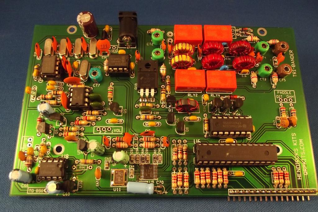
7 Assembly Instructions: The quickest and easiest way to build the rig is in layers. The lowest profile parts are installed first, such as resistors and diodes, then higher profile parts such as capacitors and so on. Once the board is populated with all the parts, testing will be done by inserting the various Integrated Circuit chips one at a time and testing the associated stages they are used with. Before you start assembly, it is helpful to sort the parts into types and values. Using a number of paper or plastic picnic bowls to sort the parts into is a good idea to keep parts from getting lost on the bench. If you loose, damage or are missing a part, send a message to parts@qrpkits.com for a replacement. Please specify the part type and value. For example, instead of saying you need R, say you need a K resistor. Otherwise, we will have to look up the parts list for the kit and figure out what R is and that can delay getting you that part. In general, parts are numbered on the board in rows, starting with the lowest part number in the upper left corner of the board (this is the back end), and then run left to right and then zig-zag down the board to the front end. Parts will be inserted in that order. Part values are labeled on the parts placement diagram for easy reference. There are two placement diagrams included. The first is in color, which makes the various parts types stand out better, but would use a lot of ink to print out. A second, ink jet friendly diagram is also included. At least one of these diagrams should be printed out for easy reference as you build up the board. Note that the band specific parts have no value labeled. See band table for values later in manual. 7


8 Ink jet friendly diagram: 8
9 9
10 Cabinet preparation: Before starting on the board assembly, the cabinet should be prepared first. This way, it will be ready to go when you finish building the board Clean the cabinet. (optional) paint the cabinet. Apply decals. When labeling the band select switch, note that the center position should be the lowest frequency band. Attach tilt stand bale to bottom of cabinet. Attach Red film over display cutout. Trim edges as required to clear mounting studs. Hole for switch can be made with paper punch. Tape in place. Decal instructions: The decals are applied in the same manor as model decals. Cut around each group of text or symbols you wish to apply. It doesn t have to be perfect as the background film is transparent. Use the picture on the first page as a guide for where the decals go. Be sure to get the correct spacing away from the holes, as it is very easy to do a great decal installation and have a portion covered up with a knob. Thoroughly clean the surface of the panel to remove any oils or contamination. Use dish washing liquid soap and water (rise well), denatured alcohol or paint thinner. We have found that moving the decals into position on bare aluminum chassis is difficult, due to the brushed surface, so we advise pre-coating the chassis with the Krylon clear before applying the decals. (Unless you have elected to paint the chassis first) Trim around the decal. After trimming, place the decal in a bowl of lukewarm water, with a small drop of dish soap to reduce the surface tension, for 0-5 seconds. Using tweezers, handle carefully to avoid tearing. Start to slide the decal off to the side of the backing paper, and place the unsupported edge of the decal close to the final location. Hold the edge of the decal against the panel, with your finger, and slide the paper out from under the decal. You can slide the decal around to the right position, as it will float slightly on the film of water. Use a knife point or something sharp to do this. When in position, hold the edge of the decal with your finger and gently squeegee excess water out from under the decal with a tissue or paper towel. Work from the center, to both sides. Remove any bubbles by blotting or wiping gently to the sides. Do this for each decal, and take your time. Allow to set overnight, or speed drying by placing near a fan for a few of hours. When dry, spray two light coats of matte finish, Krylon, clear to seal and protect the decals, and allow to dry in between coats. All decals come with two complete sets, in case you mess one up.
11 Part by part placement guide: Resistors pay attention to values highlighted as they can be easily confused with values with similar color coding. location Value Color code R 70 Ω R 5 Ω R Location Value Color code YEL/VOL/BRN/GLD R 70 Ω RED/VOL/BRN/GLD GRN/BRN/BLK/GLD R K BRN/BLK/RED/GLD 70 K YEL/VOL/YEL/GLD R K BRN/BLK/RED/GLD R 0 K BRN/BLK/ORG/GLD R K BRN/BLK/RED/GLD R5 7.5 K VOL/GRN/RED/GLD R5 0 BRN/BLK/BLK/GLD R6 00 K BRN/BLK/YEL/GLD R6.9 K SMT PREINSTALLED R7 0 K BRN/BLK/ORG/GLD R7 70 Ω SMT PREINSTALLED R8 70 K YEL/VOL/YEL/GLD R8 MEG BRN/BLK/GRN/GLD R9 00 K BRN/BLK/YEL/GLD R9 K RED/RED/ORG/GLD R0 00 K BRN/BLK/YEL/GLD R0. K R 70 Ω RED/VOL/BRN/GLD R. K R 70 Ω RED/VOL/BRN/GLD R. K R 7 K YEL/VOL/ORG/GLD R. K R K RED/RED/ORG/GLD R. K R5 K RED/RED/ORG/GLD R5. K R6 00 K BRN/BLK/YEL/GLD R6. K R7 5 K BRN/GRN/ORG/GLD R7. K R8 MEG BRN/BLK/GRN/GLD R8. K R9 0 K RED/RED/YEL/GLD R9. K R0 70 Ω RED/VOL/BRN/GLD R0. K R K BRN/BLK/RED/GLD Molded inductors: There are four () molded inductors (RFC) to install. These look like resistors but are a little shorter and fatter. Like resistors, the value is also color coded on the body of the part. Install L5/L6. uhy ORG/ORG/GLD/GLD Install L/L7 0 uhy BRN/BLK/BLK/GLD Diodes: Be sure to observe proper polarity. Band near end of part goes towards line on part outline. Install D/D N8 small glass body Install D N587 large plastic body. Install D N756A large glass body Crystals: The crystals are now installed, the locations are shown filled in with light gray. All the crystals are matched and the same frequency, so it doesn't matter which ones go where. The cans of the X to X crystals should be tack soldered to the solder pad located next the the body of the crystal. This should be done now, as getting an iron in after the near-by capacitors are installed will be difficult. Install X to X5 NOTE: Stand X5 off the board slightly, to avoid shorting to pad on C IC sockets: IC sockets are now installed. Make sure notch in socket is aligned with notch on part outline on board. Before soldering, make sure they are flush to the board and that all the pins are sticking out of the holes on the bottom of the board. If a pin gets bent over as you are inserting the socket, this will be difficult to fix later. U, U, U, U8 8 pin socket
12 U pin socket U6 8 pin socket Capacitors: There are four types of capacitors used. Some caps may have lead spacing too wide for the board holes. Please take a few minutes to unkink the formed leads (typically the MONO caps) and straighten them out so the cap sits properly to the board. Multi-layer (MONO) caps, which are generally yellow and rectangular is shape. NPO type disks will have a black dot on the top edge of the cap. Note. Some of the ceramic disk caps will have lead spacing wider then the hole spacing on the board. In this case, use your needle nose pliers to kink both leads inward slightly to match the board hole spacing. Film capacitors. These will be green in color. Aluminum Electrolytic. These are round cylinders and have polarity. They must be installed with the correct polarity. Electrolytic caps inserted with the wrong polarity across the DC supply can heat up and explode! The negative lead is marked with a black stripe and the positive lead is always the longer lead. Capacitor value markings: The capacitor value is marked on the part with a two or three digit number and is read in picofards. The third digit is the zero multiplier. Values of less than 00 pfd generally show only two digits, but sometimes three. Therefore, if a part is marked 70, that means it is a 7 pfd cap and not a 70 pfd cap. A 70 pfd cap would be marked 7. Mono caps also often have letters printed on the part. These letters indicate the type or tolerance and can be disregarded. NOTE: Electrolytic, band specific values (will be installed later) and pre-installed SMT caps are not listed in table below location value type C 0. ufd (0) C location value type C7 0.0 ufd (0) FILM, GREEN 00 pfd (0) NPO DISK, BROWN C8 0.0 ufd (0) FILM, GREEN C5 00 pfd (0) NPO DISK, BROWN C9 0.0 ufd (0) FILM, GREEN C9 00 pfd (0) NPO DISK, BROWN C0 0. ufd (0) C 00 pfd (0) NPO DISK, BROWN C.00 ufd (0) DISK, BROWN C 00 pfd (0) NPO DISK, BROWN C.00 ufd (0) DISK, BROWN C5 0. ufd (0) C 0. ufd (0) C7 pfd () DISK C5 0. ufd (0) C 0. ufd (0) C6 0. ufd (0) C 00 pfd (0) NPO DISK, BROWN C7 00 pfd (0) NPO DISK, BROWN C7 0. ufd (0) C8 0. ufd (0) C8 0. ufd (0) C9.00 ufd (0) DISK, BROWN C9 00 pfd (0) C50 pfd () DISK NPO C0 0. ufd (0) C5 7 pfd (7) DISK NPO C 70 pfd (7) DISK, BROWN C5 pfd () DISK NPO C 0. ufd (0) C5 0. ufd (0) C 0. ufd (0) C55.00 ufd (0) DISK, BROWN C 0. ufd (0) C56 0. ufd (0) C5 70 pfd (7) DISK, BROWN C6 0. ufd (0) C6 0. ufd (0) C65 0. ufd (0) C67.00 ufd (0) DISK, BROWN


13 Trimmer capacitor CT 7 Green trimmer. Make sure the flat side of the part is facing the line drawn in the circle outline on the board. Transistors: Be sure to properly ready the part number on the three legged transistors so they go in the proper place. A magnifying glass maybe helpful for this. When installing the part, look out of thin shavings of the plating on the leads which might come off as you push the legs into the holes. These can cause shorts between the leads. Space the package about /8 above the board no not push real close to the board. Also, be sure to orientate the flat side of the package with the flat side of the part outline. Note that the leads of some the parts will have to be reformed to match the pad pattern on the board. Install Install Install Install Install Install Install Q, Q, Q BS70 mosfets these are static sensitive! Q, Q6, Q8 N7000 mosfets these are also static sensitive. Q9 N90 NPN Q5 N89 j-fet Q7 J-76 j-fet U5/U0 78L05 regulator Q0, FQPF7P06 or FQPFP06 bend leads 90 degrees to body and mount flush to board. Now install all the Electrolytic capacitors. Be sure to observe proper polarity. Long lead is plus side. Black stripe on the body of the can indicates negative side. C can explode if installed backwards! C - 0 ufd /6V C, C69. ufd /6V C5, C6 0 ufd /6V C66, C70 7 ufd /6V NOTE: install C70 laying on it's side. DC power jack and relays. C70 mounting Install DC power jack Install the four () relays, RLY, RLY, RYL and RYL. Note the line on one end of the relay and match this with the line on the board relay outline. Be sure to double check before soldering. If you get it in backwards, it's real hard to remove. Wind L7 0 turns #8 magnet wire on FT7- core (black) Do not install at this time, put aside for use later after initial board testing. Modification: a K resistor is added to the bottom of the board, connected to pins and of U. While not required for operation, it does reduce distortion on the output of the op-amp for large signals and improves the quality of the audio. Front, left side of board. Add K between pins and of U.
14 Band specific parts: Part locations are listed in table for band A, then band B and then Band C. The lowest frequency band should be made band A and the highest frequency band C. For example, band A could be 80 meters, while band C would be 5 meters, but not the other way around. This ensures the highest frequency band has the shortest track lengths. On the color parts layout, band A parts are shown highlighted in light Blue, band B parts in Orange and band C parts in Red. Be sure to count the turns on the low pass filter coils, L8 through L correctly. Each time the wire passes through the center of the core, this is one turn. Having one extra turn, which is a common mistake, will result in reduced power output. Also the turns should be reasonably tight to the core. Sloppy winding can result in reduced performance. Evenly space the turns around the core. 80 Value A Type 0 Will always be band A A B C Value Type C 00 pfd 0 NPO Disk C C C0 68 pfd NPO disk C 680 pfd 68 mono C0G C, C8 C7 0 pfd () C0G C 500 pfd 5 mono C0G C C6 C0 680 pfd (68) C0G C6 680 pfd 68 mono C0G C6 C5 C 0 pfd () C0G C9 5 pfd 5 NPO Disk C9 C8 C6 0 pfd NPO disk CT5/6 70 pfd Brown trimmer CT5/6 CT/ CT/ 70 pfd trimmer Brown L turns #0 wire T7- Red L L0 L8 8 turns #8 wire T7- Red L 9 turns #0 wire T7- Red L L L9 0 turns #8 wire T7- Red L5/6 9 uhy ORG/WHT/BLK/GLD L5/6 L/ L/ uhy BRN/RED/BLK/GLD Value Type 0 A B C 0 Value Type C0 pfd NPO Disk C mono C0G C6 C0 0 mono C0G C5 C 50 5 mono C0G C8 C6. pfd. NPO Disk CT5/6 CT/ CT/ 0 pfd Green trimmer L L0 L8 turns # 8 wire T7-6 Yellow #8 wire T7- Red L L L9 6 turns #8 wire T7-6 Yellow GRY/RED/GLD/GLD L5/6 L/ L/ 5.6 uhy GRN/BLU/GLD/GLD Type 5 Value Type A B C 5 NPO disk C C C0 5 pfd 5 NPO disk 7 pfd 7 mono C0G C, C8 C7 7 pfd 7 mono C0G 0 pfd mono C0G C C6 C0 0 pfd mono C0G C 00 pfd 0 mono C0G C6 C5 C 00 pfd 0 mono C0G C6. pdf. NPO Disk C9 C8 C6. pfd. NPO Disk CT/ CT/ 0 pfd Green trimmer CT5/6 CT/ CT/ 0 pfd Green trimmer L L0 L8 turns # 8 wire T7-6 Yellow L L0 L8 turns #8 wire T7-6 yellow L L L9 6 turns # 8 wire T7-6 Yellow L L L9 turns #8 wire T7-6 yellow L5/6 L/ L/. uhy ORG/ORG/GLD/GLD L5/6 L/ L/. uhy ORG/ORG/GLD/GLD A B C C C C0 7 pfd 7 NPO Disk C C C C8 C7 0 pfd mono C0G C, C8 C C6 C0 560 pfd 56 mono C0G C C6 C5 C 0 pfd mono C0G C6 C9 C8 C6.7 pfd.7 NPO Disk C9 CT5/6 CT/ CT/ 0 pfd Green trimmer L L0 L8 turns #8 wire T7- Red L L L9 7 turns L5/6 L/ L/ 8. uhy Value A B C C C C0 5 pfd C C8 C7 C C6 C0 C6 C5 C9 C8 CT5/6 7
 R, K")
 flush to the board and solder pins from front side of board.")
15 60 Meter value Type C 50 pfd 5 mono C0G C8 680 pfd 68 mono C0G C C6 00 pfd mono C0G C6 C5 680 pfd 68 mono C0G C9 C8.7 pfd.7 NPO Disk CT5/6 CT/ 70 pfd Brown trimmer L L0 0 turns #8 wire T7- Red L L 0 turns #8 wire T7- Red L5/6 L/ uhy RED/RED/BLK/GLD A B C C Front panel board assembly: R, 7 K (YEL/VOL/ORG/GLD) R, K (ORG/ORG/ORG/GLD) R, 0 K (BRN/BLK/ORG/GLD) C7, 0 disk C7, 0 Disk LED display module. This can only go in one way, keyed to missing pins on display and board. Tactile PB Switch. This can also go in only one way. NOTE: Clip leads along bottom side of switch (just above the holes for the SIP pins) flush to the board and solder pins from front side of board. Clip these leads as flush to the board as possible. Encoder. Mating Front panel board to Main board: Insert long leads of SIP pin strip up through bottom side of main board. Make sure it is seated against the board along it's length. Solder pins and clip off excess pin length Attach front panel board to pins. Very little of the pins will stick through the pads on the front panel board. Solder one pin on the end of the strip from the back side of the board. Make sure front panel board is pushed tight up against edge of main board and is at an exact right (90 degree) angle to the main board. Solder the rest of the pins.

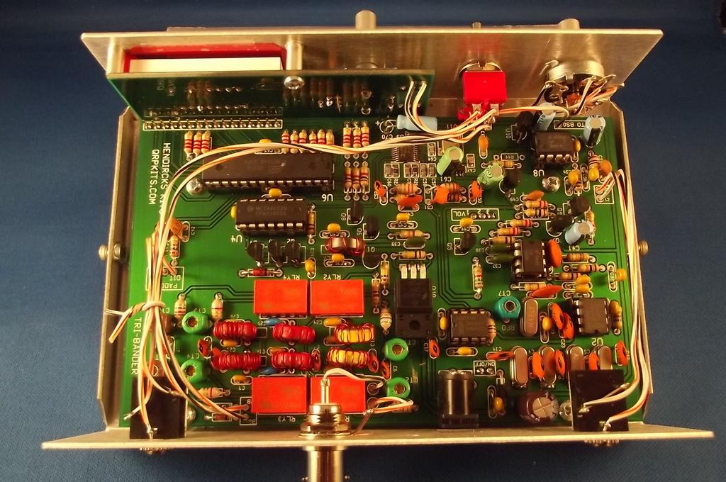
16 Board mounting into cabinet and wiring: (see photo next page) The band select switch and volume control are best wired to the board before it is installed into the case. Cut the hook up wire to the lengths listed in the table. Wires connecting to the on/off switch and volume control should be routed under the board. The two wires connecting from the band switch to the relays should be routed as shown in the diagram and not the shortest possible path diagonally across the board. Insert and solder the wires for the rear panel jacks, headphone, paddle and antenna. The board is now inserted into bottom section of the case by angling it in, making sure the shaft for the tuning encoder and Keyer PSB switch are lined up with their respective holes. In addition, the Band select switch and volume control will need to lined up and inserted into their mounting holes before the board can be fully inserted into the cabinet bottom. Once the board is in place, the headphone, paddle and antenna jacks can be installed and wired up. On/Off wires, 5 long VOL,, wires, long RLY BB/BC wires, 7 long Band SW BSB/BSC wires,.5 long Band SW BS0 wire,.5 long Phones/Spkr wires,.5 long Paddle wires,.5 long ANTENNA (BNC jack) wires, long Solder center terminal of BSB/BSC switch section to mounting tab of encoder to pick up ground. NOTE: band select switch shown mounted so toggle is vertical (up and down). 6

17 Assembled board, wired into case: Note how wires float above the board. 7
18 Power up and test:... Wire up the power plug, center pin plus. Connect to power supply, plug into power jack on rig. Turn power on via volume control. Test for 5 volts between pins 8 and of U or U (tests analog reg, U5) and between pins and 7 of U (tests digital reg, U0).. Remove power from rig. 5. Insert ATMEGA-8 chip into U6 socket. Just in case you put the socket in backwards, verify chip direction with parts layout diagram. 6. Insert LM86 chip into U8 socket 7. Plug a paddle into the paddle jack. 8. Plug speaker or headphones into headphone jack 9. Apply power to rig and turn on. 0. The display should now come on and read [ba8.0] You must now program the processor so it knows which frequency (in meters) you have selected for band A, B and C. ba80 shown on the display indicates band A is currently set to 80 meters. Change the band setting by tapping the DOT paddle. This will advance the setting from 80 to 60, 60 to 0 and so on. The display will change accordingly and a beep will sound. [ba8.0], [ba6.0] and so on. After 7 meters, the selection will roll over back to 80 meters. This is done in case you go past the band you wanted, as there is no decrement switch. Once the proper band setting is selected, advance to the next band to be set by clicking the keyer switch located under the display. The next higher frequency band will automatically be selected and displayed. Select the band setting for the B band Click keyer switch to advance to C band. Select the band C band Click the keyer switch to finish. The rig will reset to it's normal operation. If a mistake is made or at some point you what to change the filters on one of the band positions to operate on a different band, the band select mode can be enabled by holding closed the DASH paddle and the KEYER switch while turning power to the rig on. The keyer will now be operational and you can send some Morse. Receiver testing and BFO adjustment:.... Disconnect power from rig Insert SA6A chips into U and U sockets Insert LM58 into U socket. Insert LM86 into U8 socket. Hold closed the DOT paddle and KEYER switch while turning power to the rig on. The rig will now be in a calibration mode and the display will show [CAL.r] If an accurate frequency counter is available, the D reference frequency can now be calibrated. Since the typical frequency error is usually 50 Hz or less, the calibration can be skipped by going to step if a suitable frequency counter is not available D frequency can be picked off of Pin 7 on U or at the U9, Pin 0/C60 junction. The D frequency is calibrated to exactly 0.000,000 MHz Use the Dot and Dash paddles to tune the D frequency up or down as required to set the frequency to 0.000,000 MHz. Finish by clicking the KEYER switch. This will advance to the offset/bfo adjust mode. The display will now show [CAL.o] If an Oscilloscope is available (it can be audio PC based 'Scope) the IF offset frequency can be set in addition to the BFO frequency. If a 'Scope is not available, the BFO trimmer will have to be set by ear. (skip to step 6). Connect the 'Scope to pin 7 of U (output of st audio stage).. Preset BFO trimmer (CT7) about ¼ turn.. Using the paddle, tune LO frequency up and down, noting the point at which the signal amplitude starts to drop off.. Tune the LO frequency be more or less centered in the pass band of the IF filter. 5. Move the 'Scope to pin of U (or top of volume control) 6. Adjust BFO trimmer to peak signal in pass band of Audio Filter. If a 'Scope is not available, peak by ear, keeping volume control turned down so that AGC is not engaged. 7. Once adjustments are finished, click the KEYER switch again to store these values and rest the rig.
19 NOTE: When entering the Calibration mode, the default frequency values for reference and IF offset are loaded. This is done in case the values now stored in EEPROM become corrupted. Therefore, it is not possible to test the calibration by re-entering the calibration mode. If you wish to test the calibration, measure the transmit frequency on the highest band you have chosen to install into the rig, before and after calibration. If you were able to set the BFO trimmer, everything up to the st mixer is working correctly. You can now connect up an antenna (or signal generator) and peak the receiver input trimmer caps for each band. Peak for band noise or signal strength. The receiver will be quite deaf until the trimmers are properly peaked. Transmitter testing: Remove power supply from board. Insert the 7AC0 into U socket Install L7. You will need to remove the board from the case to do this. Connect power meter and dummy load to antenna jack. Plug a straight key into the paddle jack or close the Dash paddle when turning on power so transmitter can be keyed on and off. Check power output on all three bands. Using a.8 volt supply, the power output should be about 5 watts. Power output can be tweaked to some extent by changing the spacing of the turns on the low pass filter cores. With a little experimentation, it should be possible to achieve 5 watts output on each band. Coils L8, L0 and L will have the most effect on power output. These are the inductors which follow the PA FETS, and influence the matching between the PA and load. When the turns on L8. L0 and L are most evenly spaced around the core, this will result in the maximum power output. Moving the turns closer together will reduce power output. The inductors L9, L and L also have some effect on power output. These work opposite of the input side inductors, moving the turns closer together reduces power output. If you have little or no power output and can not peak the receiver input with the trimmer caps, you probably have the wires from the band selector switch to the relays reversed and have the wrong filters selected for that band. Pretty easy to get it wrong. Volume tweaks: 9 If you use an external speaker instead of headphones most of the time, you might find the maximum volume a little low. The maximum audio level is set by the AGC circuit. Removing R9 (0K) will eliminate the bias on the base of Q, resulting in requiring a higher audio level before AGC action kicks in.
20 Trouble shooting guide: In most cases, any problems with the getting the rig to work will be tracked down to soldering problems or miss placed parts. A close visual inspection of the board is often enough to find soldering problems or the miss-placed parts. Soldering problems fall into four groups:. Missing solder connections. Solder bridges between closely spaced pads which should not be connected togther.. Solder which stuck to the part lead but did not flow into the solder pad on the board. This is often caused by not using enough heat or not placing the iron tip on both the lead and the solder pad.. Not making connection to the wires on the toroid coils. Even if you pre-tined the magnet wire, you may have pulled it past the tinning when inserting the wires into the board and are not making a connection. Buzz out the connection to ensure continuity. Miss-placed parts: The most common error here is not reading the resistor color code correctly. Some values have identical colors, but in a different order. It is easy to mistake a 5 ohm resistor (Green/Brown/Black) for a Meg resistor (Brown/Black/Green) Trouble shooting technique: The trick to trouble shooting is being able to narrow down the area to look at to find the problem. Just using a DVM will be sufficient for basic trouble shooting. For more difficult cases, an Oscilloscope and signal generator may be needed to track signals through the circuits. In any case, one should first determine which parts of the circuit are working properly and this will lead you to what is not. If the rig is completely dead, the problem is likely with the power supply and could very well be a short to ground somewhere on the 5 volt supply feeding most of the IC's. If the display comes on, the microprocessor is working and if you get side tone when you use the paddle, or hear hiss when the volume control is turned all the way up, the audio amp is working. If there is no side tone or hiss, the problem maybe a simple as the wiring to the speaker/headphone jack or you may have forgotten to install the two SIP pins to the left of the main row of pins. If missing pins is the problem, use resistor lead clippings to make the connections, as unsoldering the main row of pins to add the missing ones will be difficult. If you get audio, but can not hear any off air signals, the problem is more difficult to find as it could be anywhere between the antenna jack and the audio amp. In this case having a signal generator and Oscilloscope are of great help in tracing the signal though the circuits. Transmitter: There is not a whole lot which can go wrong with the transmitter portion. Check for PA keying voltage coming out of Q0, proper soldering of the toroid magnet wire. Also make sure the proper filters are being selected with the band switch! The voltage tables below may be of help. U 7AC0 PA driver, Quad NOR gate U/U SA6A Mixers U LM58 audio preamp / BP filter Pin# Voltage Pin# Voltage Pin# Voltage Pin# Voltage Pin# Voltage Pin# Voltage 0.V 8 8 DCIN 0 0.V V 6 0V.9V 5.9V 0 (GND) Pin/ signal in Pin /5 signal out Pin 6 Osc in Pin 7 Osc out DCIN = board supply voltage, less diode drop. DC Voltage on pins 6/7 maybe influenced by RF present on pins. U6 MEGA8 Microprocessor U8 LM86 audio power amp Volt 0V 0V 0V 0V 0V 5/0 5/0 Pin# Voltage Pin# Voltage Pin# V 8.V Pin# ½ DCIN Volt 0V 0 6 DCIN 0 (GND) 5 ½ DCIN 0V = Display segment or digit select voltage varies depending on digits displayed and duty cycle. Pins 5/6 Tuning encoder inputs, voltage depends on position of encoder, may be high () or low (0V) 0
21 Schematics:
22
The KD1JV Tri-Bander CW transceiver QRP kits dot com
 The KDJV Tri-Bander CW transceiver QRP kits dot com www.qrpkits.com Table of Contents Operation:... Message pause and stop...3 Power on/off:... Straight key mode:...3 Band selection:... Tune up mode:...
Dual Band HF CW transceiver Hendricks kits and KD1JV Designs QRPKITS.COM
 Dual Band HF CW transceiver Hendricks kits and KDJV Designs QRPKITS.COM Updated 5//9 Specifications: Any two ham bands, 8, 4,,, 7 or 5 meters, choose at time of order. 5 watts output on all bands with.8v
Dual Band HF CW transceiver
 Dual Band HF CW transceiver Hendricks kits and KD1JV Designs QRPKITS.COM Specifications: Any two ham bands, 80, 40, 30, 20, 17 or 15 meters, choose at time of order. 5 watts output on all bands with 13.8V
The Deluxe Tenna Dipper Design by: KD1JV Distributed by: Hendricks QRP kits,
 The Deluxe Tenna Dipper Design by: KD1JV Distributed by: Hendricks QRP kits, www.qrpkits.com The Tenna Dipper provides a simple means of determining the 50 ohm resonate frequency of an HF antenna or ATU
Pacific Antenna SLT+ Switched Long wire Tuner
 Pacific Antenna SLT+ Switched Long wire Tuner The SLT+ is designed to match the high impedance load of an end feed, half wave antenna wire to a 50 ohm transmitter using manually switched inductors and
The DCxxB family of transceivers
 The DCxxB family of transceivers High performance Direct Conversion transceivers for 40, 30 and 0 meters. A KDJV Melt Solder design Distributed by Pacific Antenna www.qrpkits.com Join Yahoo's DC40 kits
PFR-3B Portable Field Radio
 PFR-3B Portable Field Radio Specifications: Bands : 40 meters, 30 meters and 20 meters Tuning range: Full band coverage DDS VFO with 50 Hz slow tuning rate and 200 Hz fast tuning rate Mode: CW only Receiver
 The Mountain Topper by Steve Weber (KD1JV) (MTR) www.lnrprecision.com FULLY ASSEMBLED Manufactured by LNR Precision, Inc. A very small, very efficient three band QRP CW rig. Specifications: Three bands,
The DCxxB family of transceivers
 The DCxxB family of transceivers High performance Direct Conversion transceivers for 40, 30 and 20 meters. Evolution of the popular DC40 to the DCxxB series on 40,30 and 20 meters A KD1JV Melt Solder design
Read This Page First
 Read This Page First If you are reading this you know the manuals are always available at QRPKITS.com. This is version 8.0 of the manual dated 4/27/2016. There is no need to print out the whole assembly
Pacific Antenna Simple Keyer Kit
 Pacific Antenna Simple Keyer Kit Specifications and Features: Speed range of 5 to 30 wpm Operates in either iambic A or B mode, with B being the default 2 message memories Tune and Beacon modes Built on
The MBDC. A Multi-Band, Direct Conversion Transceiver. Steven Weber, KD1JV Distributed by Pacific Antenna,
 The MBDC A Multi-Band, Direct Conversion Transceiver Steven Weber, KD1JV steve.kd1jv@gmail.com Distributed by Pacific Antenna, www.qrpkits.com Specifications: Rx current: 80 M : 70 ma, 160 M : 100 ma Sensitivity:
The NADC. A CW rig using Nearly All Discrete Components Manual for 40 meter and 30 meter versions Hendricks QRP Kits
 The NADC A CW rig using Nearly All Discrete Components Manual for 0 meter and 30 meter versions Hendricks QRP Kits www.qrpkits.com Show with optional Digital Dial installed Specifications: Receiver: Tuning
Building the Sawdust Regenerative Receiver
 Building the Sawdust Regenerative Receiver Introduction The Sawdust is a super regenerative receiver using the basic Armstrong design architecture. The receiver uses one toroidal transformer to provide
Building the Sawdust Regenerative Receiver
 Building the Sawdust Regenerative Receiver Introduction The Sawdust is a super regenerative receiver using the basic Armstrong design architecture. The receiver uses one toroidal transformer to provide
The Survivor A 80 meter QRP SSB transceiver
 The Survivor A 8 meter QRP SSB transceiver ~ watts pep @.8V. uv receiver sensitivity Up to khz tuning range 8 ohm mw speaker output. Tune and CW modes ma Rx current (with optional Digital Dial) small size
Hendricks RockHunter CW Transceiver w/switched crystal board assembly instructions
 Hendricks RockHunter CW Transceiver w/switched crystal board assembly instructions First off, check to see if the parts match the parts list 1 band specific additional crystal 1 3 pin SIP socket 1 DP3T
The PFR-3 Three band Portable Field Ready QRP CW Transceiver 40/30/20 meters Hendricks Kits KD1JV Designs
 The PFR-3 Three band Portable Field Ready QRP CW Transceiver 40/30/20 meters Hendricks Kits www.qrpkits.com KD1JV Designs Production manual 6/10/08 Rev B Specifications: PFR-3 shown with optional paddle
The Survivor A 80 meter QRP SSB transceiver
 The Survivor A 8 meter QRP SSB transceiver Up to ~ 8 watts pep @.8V +/- khz.. uv receiver sensitivity Up to khz receiver tuning range 8 ohm mw speaker output. Tune and CW modes ma Rx current (with optional
The MBDC. A Multi-Band, Direct Conversion Transceiver. Steven Weber, KD1JV Distributed by Hendricks kits,
 The MBDC A MultiBand, Direct Conversion Transceiver Steven Weber, KDJV steve.kdjv@gmail.com Distributed by Hendricks kits, www.qrpkits.com Specifications: Features: Rx current: X6 LCD display 8 M : 7 ma,
KN-Q10 Assembly Manual
 KN-Q10 Assembly Manual Translated by Adam Rong, BD6CR/4 with permission from Ke Shi, BA6BF Edited by Stephen, VK2RH Revision B, Oct 14, 2010 Thank you for purchasing the KN-Q10 4 Band SSB/CW Dual Mode
The Survivor A 80 meter QRP SSB transceiver
 The Survivor A 8 meter QRP SSB transceiver Up to watts pep @ 3.8V. uv receiver sensitivity Up to 3 khz receiver tuning range Hz warm up drift. (stable room temperature) 8 ohm mw speaker output. Tune and
Building a Bitx20 Version 3
 Building a Bitx20 Version 3 The board can be broken into sections and then built and tested one section at a time. This will make troubleshooting easier as any problems will be confined to one small section.
Arizona ScQRPion QRP Club. Ft Tuthill w DC CW Transceiver for 80m Part 1 of 2. by Dan Tayloe, N7VE. Ft Tuthill Page 1 of 31
 Arizona ScQRPion QRP Club Ft Tuthill 80 2.5w DC CW Transceiver for 80m Part 1 of 2 by Dan Tayloe, N7VE Page 1 of 31 Table of Contents Specifications... 4 Specifications... 4 Receiver... 4 Transmitter...
MTR-3B - LCD edition
 MTR-3B - LCD edition Mountain Topper User Manual Overview: The Mountain Topper Rigs are designed to be a very small, light weight, very battery efficient, multi-band CW rig suitable for field operation.
Building the Toothpick Audio CW Filter
 Building the Toothpick Audio CW Filter Introduction The toothpick is a simple variable bandpass audio filter designed to compliment the Splinter QRPp Trans-Receiver. The filter also contains an audio amplifier
Hendricks QRP Kits The Twofer Rev
 Hendricks QRP Kits The Twofer Rev 1 11-15-06 1. Description The Twofer is a classic QRP transmitter that s easy to assemble and operate. It uses a JFET VXO (variable crystal oscillator), driver stage and
N3ZI Kits General Coverage Receiver, Assembly & Operations Manual (For Jun 2011 PCB ) Version 3.33, Jan 2012
 Version 3.33, Jan 2012") N3ZI Kits General Coverage Receiver, Assembly & Operations Manual (For Jun 2011 PCB ) Version 3.33, Jan 2012 Thank you for purchasing my general coverage receiver kit. You can use the photo above as a
N3ZI Kits General Coverage Receiver, Assembly & Operations Manual (For Jun 2011 PCB ) Version 3.33, Jan 2012 Thank you for purchasing my general coverage receiver kit. You can use the photo above as a
LNR Precision Mountain Topper MTR-4B and MTR-5B REV 2.0 User Manual for use with versions with 16 x 2 display.
 LNR Precision Mountain Topper MTR-4B and MTR-5B REV 2.0 User Manual for use with versions with 16 x 2 display. Four band MTR 4B shown Overview: The Mountain Topper Rigs are designed to be a very small,
Connecting the FCC-2 to the Hendricks DC Kits Bob Okas, W3CD
 Connecting the FCC-2 to the Hendricks DC Kits Bob Okas, W3CD This is an application note that describes how you can connect the NorCal FCC-1/2 combination to the DC kits. It involves a few extra components
The DC40. A high performance Direct Conversion 40M transceiver. A KD1JV Melt Solder design Distributed by Hendricks QRP KITS
 The DC40 A high performance Direct Conversion 40M transceiver. A KD1JV Melt Solder design Distributed by Hendricks QRP KITS www.qrpkits.com 1 The DC40 A Direct Conversion, fixed frequency Transceiver.
Easy Transmitter. Support ETX_REV5_Manual V2.7 Revised
 Easy Transmitter Introduction The Easy Transmitter kit from qrpkits.com provides a basic, crystal controlled transmitter with VXO tuning to provide a small tuning range around the crystal frequency. It
Wiring Manual NEScaf April 2010 (August 2006)
") Wiring Manual NEScaf April 2010 (August 2006) Switched Capacitor Audio Filter The NEScaf is a switched capacitor audio filter (acronym SCAF) built around a building-block type filter chip. The NEScaf will
Wiring Manual NEScaf April 2010 (August 2006) Switched Capacitor Audio Filter The NEScaf is a switched capacitor audio filter (acronym SCAF) built around a building-block type filter chip. The NEScaf will
The ROSE 80 CW Transceiver (Part 1 of 3)
") Build a 5 watt, 80 meter QRP CW Transceiver!!! Page 1 of 10 The ROSE 80 CW Transceiver (Part 1 of 3) Build a 5 watt, 80 meter QRP CW Transceiver!!! (Designed by N1HFX) A great deal of interest has been
Build a 5 watt, 80 meter QRP CW Transceiver!!! Page 1 of 10 The ROSE 80 CW Transceiver (Part 1 of 3) Build a 5 watt, 80 meter QRP CW Transceiver!!! (Designed by N1HFX) A great deal of interest has been
Pacific Antenna Easy Transmitter Kit
 Pacific Antenna Easy Transmitter Kit Introduction The Easy Transmitter kit from qrpkits.com provides a crystal controlled transmitter with VXO tuning. The circuit consists of a N3904 based crystal oscillator
Build this Direct Digital Synthesizer "Development Kit" By: Diz Gentzow, W8DIZ
 Build this Direct Digital Synthesizer "Development Kit" By: Diz Gentzow, W8DIZ A great tutorial for adding a keypad to the DDS Kit by Bruce, W8BH This manual has been prepared to be read directly on screen.
Fabricated PCB chassis for the W8DIZ 1 Watter Transceiver
 Fabricated PCB chassis for the W8DIZ 1 Watter Transceiver A practical chassis can be constructed for the W8DIZ 1 Watter fabricated from printed circuit board material using the commonest tools found in
Building The DC Beeper from Jackson Harbor Press A Morse code voltmeter / DC switch
 Building The DC Beeper and from Jackson Harbor Press Operating A Morse code voltmeter / DC switch The DC Beeper kit is a combination of a Morse code voltmeter with 20 mv resolution and a DC switch. The
Pacific Antenna Easy TR Switch
 Pacific Antenna Easy TR Switch Kit Description The Easy TR Switch is an RF sensing circuit with a double pole double throw relay that can be used to automatically switch an antenna between a separate receiver
HT-1A Dual Band CW QRP Transceiver. Kit Building Instructions
 HT-A Dual Band CW QRP Transceiver Kit Building Instructions Rev B, July 8, 08 Designed by BD4RG Exclusively distributed by CRKITS.COM and its worldwide distributors Join the group http://groups.io/g/crkits
Frequency Counter / Digital Dial
 Frequency Counter / Digital Dial A KD1JV Melt Solder design Distributed by Hendricks QRP Kits www.qrpkits.com Page 1 of 18 The Digital Dial is primarily intended to be used as a simple means of adding
The Walford Electronics Ford Receiver Kit Project Construction Manual
 The Walford Electronics Ford Receiver Kit Project Construction Manual Walford Electronics Ford Receiver construction manual V1.5 Page 1 of 22 Introduction The Ford receiver has four stages: The first stage
S-Pixie QRP Kit. Student Manual. Revision V 1-0
 S-Pixie QRP Kit Student Manual Revision V 1-0 Introduction The Pixie 2 is a small, versatile radio transceiver that is very popular with QRP (low power) amateur radio operators the world over. It reflects
Assembly Manual V1R2B-Rev1.0D
 Assembly Manual V1R2B-Rev1.0D for 4 State QRP MagicBox - Solid State Transmit/Receive System Designed by: Jim Kortge, K8IQY Copyright 2009-2012 - All rights reserved This system is the result of some brainstorming
The DCxxA family of transceivers
 The DCxxA family of transceivers High performance Direct Conversion transceivers for 40, 30 and 20 meters. DC30A transceiver Evolution of the popular DC40 to the DCxxA series on 40,30 and 20 meters A KD1JV
Cricket 80a Assembly Manual v Copyright David Cripe NM0S The 4 State QRP Group
 Cricket 80a Assembly Manual v. 1.0 Copyright 2017 David Cripe NM0S The 4 State QRP Group Introduction Thank you for purchasing a CRICKET 80a Transceiver. We hope you will enjoy building it and find it
E L E C R A F T K N B 1 N O I S E B L A N K E R
 Introduction E L E C R A F T K N B N O I S E B L A N K E R Assembly and Operating Instructions Revision C, Jan. 8, 200. Copyright 200, Elecraft; All Rights Reserved The KNB noise blanker can be used to
Assembly Instructions
 Assembly Instructions For the SSQ-2F 3.1 MHz Rife Controller Board Kit v1.41 Manual v1.00 2012 by Ralph Hartwell Spectrotek Services GENERAL ASSEMBLY INSTRUCTIONS Arrange for a clean work surface with
Three possible chassis for the KD1JV Para80set Transceiver
 Three possible chassis for the KD1JV Para80set Transceiver Shown above are two of the three possible variations of homemade chassis for the KD1JV Para80set Transceiver. The one on the left is a complete
Polyphase network kit
 Polyphase network kit 1. Introduction This polyphase network module is designed to be used with the QRP Labs receiver module kit. It takes as inputs, four phase audio from the Quadrature Sampling Detector
Custom Integrated Circuit (MSM9520RS) Replacement Module
 Replacement Module") FT-101Z/ FT-107/ FT-707/ FT-901,902 (later version) DISPLAY COUNTER UNIT (PB-2086A) Custom Integrated Circuit (MSM9520RS) Replacement Module Assembly and Installation Manual (v1.3e) STEP-BY-STEP PROCEDURES
FT-101Z/ FT-107/ FT-707/ FT-901,902 (later version) DISPLAY COUNTER UNIT (PB-2086A) Custom Integrated Circuit (MSM9520RS) Replacement Module Assembly and Installation Manual (v1.3e) STEP-BY-STEP PROCEDURES
Read This Page First
 Read This Page First If you are reading this you know the manuals are always available at QRPKITS.com. If you have questions contact qrpkits.com@gmail.com There is no need to print out the whole assembly
Pacific Antenna - Easy TR Switch
 Pacific Antenna - Easy TR Switch Kit Description The Easy TR Switch is an RF sensing switch that can be used to switch an antenna between a receiver and transmitter. It also has a second switched pair
HAMTRONICS TB901 FM EXCITER INSTALLATION, OPERATION, & MAINTENANCE
 HAMTRONICS TB901 FM EXCITER INSTALLATION, OPERATION, & MAINTENANCE GENERAL INFORMATION. The TB901 is a single-channel low power fm transmitter (exciter) designed to provide 300-600 milliwatts continuous
The DCxxA Family of Transceivers
 The DCxxA Family of Transceivers High Performance Direct Conversion Transceivers for 40, 30 and 20 Meters DC30A Transceiver Evolution of the popular DC40 to the DCxxA series on 40, 30 and 20 Meters A KD1JV
SoftRock v6.0 Builder s Notes. May 22, 2006
 SoftRock v6.0 Builder s Notes May 22, 2006 Be sure to use a grounded tip soldering iron in building the v6.0 SoftRock circuit board. The soldering iron needs to have a small tip, (0.05-0.1 inch diameter),
Value Location Qty Transistors 2N5485 Q1, Q2, 4 Q3, Q4 2N5087 Q5 1. Trim Pots 250k VTRIM 1. Potentiometers C500k Speed 1. Toggle Switch On/On Vibe 1
 P-90 BUILD INSTRUCTIONS Thank you for your purchase of our P-90 kit! We have completely redesigned our entire line of kits to be the most user friendly, while still maintaining their same great sound!
HF Amateur SSB Receiver
 HF Amateur SSB Receiver PCB Set for radio club project http://rhelectronics.net PCB for DIY HF Amateur SSB Receiver 20M The receiver is a simple syperheterodyne type with quartz crystal filter. The circuit
ELECRAFT KXPD1 PLUG-IN KEYER PADDLE
 Introduction ELECRAFT KXPD1 PLUG-IN KEYER PADDLE Assembly and Operating Instructions Revision B, July 27, 2011. Copyright 2011, Elecraft; All Rights Reserved The KXPD1 is a unique plug-in keyer paddle
Assembly Instructions for the FRB FET FM 70 Watt Amp
 Assembly Instructions for the FRB FET FM 70 Watt Amp 1.) Orient the circuit board with the diagram 2.) Use a narrow chisel tip 25-30 watt soldering iron for assembly 3.) All the small parts are taped onto
CW-ADD. Universal CW Adapter for SSB Transceivers. Assembly manual. Last updated: October 1,
 CW-ADD Universal CW Adapter for SSB Transceivers Assembly manual Last updated: October 1, 2017 ea3gcy@gmail.com Updates and news at: www.ea3gcy.com Thanks for building the Universal CW Adapter kit CW-ADD
Building and Operating: Son of Zerobeat A PIC based CW zerobeat indicator from Jackson Harbor Press
 Building and Operating: Son of Zerobeat A PIC based CW zerobeat indicator from Jackson Harbor Press Ed Nisley, KE4ZNU, wrote an article published in the August, September and October of 1996 issues of
Penrose Quantizer Assembly Guide
 Penrose Quantizer Assembly Guide Schematic and BOM The schematic can be found here: www.sonic-potions.com/public/penrosequantizerschematic.pdf The BOM is available at google docs: Link to BOM Prepare the
Assembly Instructions for the 1.5 Watt Amplifier Kit
 Assembly Instructions for the 1.5 Watt Amplifier Kit 1.) All of the small parts are attached to a sheet of paper indicating both their value and id. 2.) Leave the parts affixed to the paper until you are
The DC40. A high performance Direct Conversion 40M transceiver. A KD1JV Melt Solder design Distributed by Hendricks QRP KITS
 The DC40 A high performance Direct Conversion 40M transceiver. A KD1JV Melt Solder design Distributed by Hendricks QRP KITS www.qrpkits.com 1 The DC40 A Direct Conversion, fixed frequency Transceiver.
QRPGuys Michigan Mighty Might Plus 40M Transmitter
 QRPGuys Michigan Mighty Might Plus 40M Transmitter First, familiarize yourself with the parts and check for all the components. If a part is missing, please contact us and we will send one. You must use
Circuit Board Assembly Instructions for Babuinobot 1.0
 Circuit Board Assembly Instructions for Babuinobot 1.0 Brett Nelson January 2010 1 Features Sensor4 input Sensor3 input Sensor2 input 5v power bus Sensor1 input Do not exceed 5v Ground power bus Programming
LDB-1 Kit Instructions Page 1 of 8
 LDB-1 Kit Instructions Page 1 of 8 Important Information Congratulations and thank you for your purchase of the LDB-1 Little Drummer Boy Analog Drum Machine Kit! Before you start, please read the enclosed
V6.2 SoftRock Lite Builder s Notes. November 17, 2006
 V6.2 SoftRock Lite Builder s Notes November 17, 2006 Be sure to use a grounded tip soldering iron in building the v6.2 SoftRock circuit board. The soldering iron needs to have a small tip, (0.05-0.1 inch
FM Audio/Squelch Board by Steve Dold, W6KCS w6kcs (at) stevedold (dot) com
 stevedold (dot) com") FM Audio/Squelch Board by Steve Dold, W6KCS w6kcs at stevedold dot com Board hardware version 7-8 Firmware version 7.x This board connects to an FM receiver's discriminator/detector and provides squelched,
FM Audio/Squelch Board by Steve Dold, W6KCS w6kcs at stevedold dot com Board hardware version 7-8 Firmware version 7.x This board connects to an FM receiver's discriminator/detector and provides squelched,
Read This Page First
 Pacific Antenna 0 Watt HF Amplifier Kit Manual This is Version 5.5 dated 060505 Read This Page First If you are reading this you know the manuals are always available at QRPKITS.com. If you have questions
Hendricks QRP Kits BITX20A to BITX17A Conversion Instructions
 Hendricks QRP Kits BITX20A to BITX17A Conversion Instructions 30 November 2008 Converting your BITX20A Kit to a BITX17A Kit is not all that complex. It only requires that you change crystals and some resonance
Value Location Qty Potentiometers C1M Distortion 1 A10k Volume 1. Footswitch 3PDT SW1 1. Jacks 1/4 Mono 2 DC Power 1
 Distortion BUILD INSTRUCTIONS Thank you for your purchase of our Distortion+ kit! We have completely redesigned our entire line of kits to be the most user friendly, while still maintaining their same
ALX-SSB Transceiver Kit Assembly Manual
 ALX-SSB Transceiver Kit Assembly Manual 20 August 2018 REV A Transceiver This radio is based on the popular CS-Series SSB Transceiver Kit developed by Adam Rong, BD6CR/4 CRKITS.com. Thanks to B. Bartosh
Pacific Antenna Field Strength Indicator Kit
 Pacific Antenna Field Strength Indicator Kit Description The Field Strength Indicator kit from Pacific Antenna provides a visual way to monitor the presence and relative strength RF fields through the
WA3RNC 30 METER CRYSTALPLEXER TRANSMITTER KIT ASSEMBLY INSTRUCTIONS
 WA3RNC 30 METER CRYSTALPLEXER TRANSMITTER KIT ASSEMBLY INSTRUCTIONS Description The WA3RNC 30 Meter Crystalplexer is a low power crystal controlled QRP transmitter offering a significantly improved tuning
Pacific Antenna 10 Watt HF Amplifier Kit
 Pacific Antenna 0 Watt HF Amplifier Kit Description Our 0 watt Linear, HF amplifier kit is designed to increase the power output of low power transmitters. Gives up to 5dB gain and includes an input attenuator
Enhancing Your QRP Operating Enjoyment
 QRP-DWM Directional-Coupler Watt Meter Preliminary By: W5USJ CyM-Tech Documentation Services Enhancing Your QRP Operating Enjoyment PCB Assembly Top View Addendum: Correct missing toroid ground after installing
HEATHKIT HD-1410 ELECTRONICKEYER
 HEATHKIT HD-1410 ELECTRONICKEYER INTRODUCTION The HD-1410 is a compact Electronic Keyer with a built in AC power supply, mechanical paddles, sidetone oscillator and speaker in one package. It is designed
SoftRock v6.0 Builder s Notes. April 6, 2006
 SoftRock v6.0 Builder s Notes April 6, 006 Be sure to use a grounded tip soldering iron in building the v6.0 SoftRock circuit board. The soldering iron needs to have a small tip, (0.05-0. inch diameter),
Starving Student II. Starving Student II. SS2 guide. Written By: 6L guides.diyaudio.com/ Page 1 of 24
 SS2 guide Written By: 6L6 2019 guides.diyaudio.com/ Page 1 of 24 INTRODUCTION This is a build guide for the hybrid headphone/pre-amplifier. You can buy a kit at the SSII product listing on the diyaudio
LED S METER CONSTRUCTION MANUAL. LED S meter Construction Manual Issue 1.0 Page 1
 LED S METER CONSTRUCTION MANUAL LED S meter Construction Manual Issue 1.0 Page 1 Important Please read before starting assembly STATIC PRECAUTION The LED S Meter kit contains components which can be damaged
Assembly and Operating Instructions. Revision D, Aug. 20, Copyright 2002, Elecraft; All Rights Reserved
 Introduction E L E C R A F T K N B N O I S E B L A N K E R Assembly and Operating Instructions Revision D, Aug. 0, 00. Copyright 00, Elecraft; All Rights Reserved The KNB noise blanker can be used to suppress
PAT-4 POWER SUPPLY ASSEMBLY MANUAL Rev B Version
 PAT-4 POWER SUPPLY ASSEMBLY MANUAL Rev B Version 2013 AkitikA, LLC All rights reserved Revision Bp01 November 3, 2013 Page 1 of 16 Table of Contents Table of Contents... 2 Table of Figures... 2 Section
Pingable Envelope Generator
 Pingable Envelope Generator Kit Builder's Guide for PCB v1.0.3 4mspedals.com PEG This guide is for building a Pingable Envelope Generator (PEG), which is an intermediate-level kit. You should be confident
QRPGuys SMT Digital Dial/Frequency Counter
 QRPGuys SMT Digital Dial/Frequency Counter First, familiarize yourself with the parts and check for all the components. If a part is missing, please contact us and we will send one. You must use qrpguys.parts@gmail.com
INTRODUCTION OPERATING INSTRUCTIONS
 INTRODUCTION Welcome to the world of effortless CW, with the MFJ-403 you ll have a professional sounding fist in no time! Whether you re a Novice or seasoned Extra, the MFJ-403 has the features you ve
DDS VFO 2 CONSTRUCTION MANUAL. DDS VFO 2 Construction Manual Issue 1 Page 1
 DDS VFO 2 CONSTRUCTION MANUAL DDS VFO 2 Construction Manual Issue 1 Page 1 Important Please read before starting assembly STATIC PRECAUTION The DDS VFO kit contains the following components which can be
SoftRock v5.0 Builder s Notes. December 12, Building a QSD Kit
 SoftRock v5.0 Builder s Notes December 12, 2005 Building a QSD Kit Be sure to use a grounded tip soldering iron in building the QSD board. The soldering iron needs to have a small tip, (0.05-0.1 inch diameter),
Construction Manual 4m-Linear-Transverter XV4-15
 Construction Manual 4m-Linear-Transverter XV4-15 Holger Eckardt DF2FQ Kirchstockacherstr. 33 D-85662 Hohenbrunn 3207 Technical data exciter frequency: 21.0... 21.5 MHz RF frequency: 70.0.. 70.5 MHz supply
LA502 Assembly guide Main PCB Resistors - (2)
") LA502 Assembly guide Safety warning The kits are main powered and use potentially lethal voltages. Under no circumstance should someone undertake the realisation of a kit unless he has full knowledge about
LA502 Assembly guide Safety warning The kits are main powered and use potentially lethal voltages. Under no circumstance should someone undertake the realisation of a kit unless he has full knowledge about
HW-8-TR V3 PARTS LIST
 HW-8-TR V3 PARTS LIST Qty Ref Description Markings 4C2 C3 C4 C5 Capacitor Disc.1ls.1uF 104 1 C1 Capacitor Disc.2ls.1uF 100V 104 1 QSKMOD-C92 Capacitor Electrolytic 1uF 50V 1 QSKMOD Capacitor Mylar.47uF
Digital Electronics & Chip Design
 Digital Electronics & Chip Design Lab Manual I: The Utility Board 1999 David Harris The objective of this lab is to assemble your utility board. This board, containing LED displays, switches, and a clock,
The Switched Longwire Tuner SLT
 The Switched Longwire Tuner SLT Thank you for purchasing the SLT kit from Hendricks QRP Kits. This kit is a very high quality kit that you will find easy to build, yet when you finish, you will have a
ALX-SSB 5 Band Filter Assembly Manual 19 November 2018
 ALX-SSB 5 Band Filter Assembly Manual 19 November 2018 Contents Theory of Operation:... 1 Figure 1... 2 Parts Included:... 4 Board Overview:... 5 Figure 2... 5 Figure 3... 5 Board Assembly:... 6 Cable
RECEIVER TEST OSCILLATOR Rev G, January 16, 2018 Copyright 2018, Elecraft, Inc., All Rights Reserved
 E L E C R A F T XG RECEIVER TEST OSCILLATOR Rev G, January 6, 08 Copyright 08, Elecraft, Inc., All Rights Reserved Introduction The Elecraft XG is a crystal oscillator with accurate µv and 50 µv output
MP573 Assembly guide. Soldering. MP573 Assembly guide PCB split PCB split. Document revision 2.2 Last modification : 22/08/17
 MP573 Assembly guide Safety warning The kits are main powered and use potentially lethal voltages. Under no circumstance should someone undertake the realisation of a kit unless he has full knowledge about
BITX40 with Raduino - tips and mods
 BITX40 with Raduino - tips and mods Also check out hfsigs blogspot http://bitxhacks.blogspot.co.uk/ Clicks during tuning I assume you are talking about the Raduino clicking as you tune. I'm not having
Mono Amplifier. LM386 Headphone Amp
 Mono Amplifier LM386 Headphone Amp Layout On/Off Switch - cuts power to the circuit Mono Input Jack: use either L or R or solder together Schematic Step 1 - Parts List 1.) R1-10ohm Resistor - Brown Black
Step by Step Building PJ meter ARDF Receiver Kit. CRKITS.COM August 5, 2013
 Step by Step Building PJ-80 80-meter ARDF Receiver Kit CRKITS.COM August 5, 2013 What is ARDF? ARDF is the abbreviation of Amateur Radio Direction Finding, or so called Fox Hunting. If you are looking