Christian Römelsberger (CADFEM GmbH) Ivan Vukosav (Yazaki)
|
|
|
- Susan Simpson
- 6 years ago
- Views:
Transcription


1 Titelmasterformat TDR of a Connector durch with Klicken wiring Harness bearbeiten Christian Römelsberger (CADFEM GmbH) Ivan Vukosav (Yazaki) 1
2 Products Service Knowledge Full scale CAE solution based on ANSYS, complementary software and IT infrastructure Create confidence and reliability in optimized product development by simulation driven engineering Comprehensive and innovative background knowledge for users, supervisors, and managers Requirement analysis Configuration Integration Increase the breadth and depth of simulation usage Qualified training Reliable user support Transfer know-how to break the hurdles of adoption Information exchange Quality assurance Life long learning 2
3 Aspects of Signal Transmission Information transferred by current or voltage Signals propagate with the speed of light Wires Wave propagation on transmission line guided waves. 3


4 Aspects of Signal Transmission Connectors are imperfections in a transmission line Transmission line Wires are separating The guided waves scatter on the imperfection of the connector leading to: Reflection of the signal Cross talk Leakage of radiation from the connector At high data rates high frequencies scattering can occur For good signal quality Design that avoids scattering No jumps in impedance! 4

5 TDR Calcultate TDR to detect jumps in impedance and their location Impedance different from 50 Ω 5


6 Telegrapher s equation Want to understand TDR in a more quantitative way! A transmission line model describes the propagation of a guided TEM wave quantitatively x In the continuum limit this leads to 6


7 Telegrapher s equation For constant c(x) and l(x) the solution for constant frequency is The propagation speed of the wave is v0. The impedance of the transmission line is Z0, this relates the voltage to the current. 7
8 Scattering along a transmission line Consider a jump in impedance of the transmission line at x0. A wave solution at a given frequency has the form Z 1, v 1 Z 2, v 2 Incoming wave Reflected wave x 0 Transmitted wave 8


9 Scattering along a transmission line The requirement that the voltage and the current are well defined at the interface at x0 leads to This relation makes it possible to determine the jump in impedance from the reflected signal. The frequency dependant phase relation allows to determine the position of the jump. Note that the ratio of the reflected voltage to the incoming voltage is the return loss 9


10 TDR The position of the impedance jump can easily be determined in the time domain from the reflected signal. If the incoming signal has the frequency content then the reflected voltage is 10

11 TDR The impedance Z2 is then This is used to determine the profile of the impedance of the transmission line. There are a few things to be noted here: The transmission line has to be terminated properly on both ends. A continuous change in impedance over the distance can be viewed as many small jumps. If there is a continuous change in impedance or many jumps, it is assumed that the reflections are weak enough such that waves are not reflected back and forth too much. 11
 Setup2 : Sweep 115.00 110.00 where n is the number of time steps per rise time. 105.00 100.00 95.00 90.00 0.00 100.00 200.00 300.00 400.00 500.00 600.00 700.00 800.")
12 TDRZt(Diff1) TDR of the Connector In order to calculate a TDR with a rise time trise there has to be a frequency sweep up to TDR Connector Curve Info TDRZt(Diff1) Setup2 : Sweep where n is the number of time steps per rise time Time [ps] >100Ω 100Ω >100Ω 100Ω >100Ω 12


13 Modeling the Twisted Pair For a rise time of 35ps this leads to frequencies of up to 70GHz, i.e. waves of a wave length as small as 4mm. For a twisted pair cable with a pitch of 11mm and a length of 1m it becomes computationally unfeasible to perform a direct field calculation of the TDR! 13
14 Modeling the Twisted Pair The strategy is to divide and conquer : A single pitch can easily be simulated in a FEM simulation using ANSYS HFSS. Many pitches can be put together in a system simulation using ANSYS Designer. 2_N 1_N Port2_N Port1_N Port2_N Port1_N Port2_N Port1_N Port1_N Port2_N Port1_N Port2_N Port1_N Port2_N Port1_N Port2_N 2_P 1_P Port2_P Port1_P Port2_P Port1_P Port2_P Port1_P Port1_P Port2_P Port1_P Port2_P Port1_P Port2_P Port1_P Port2_P 14
15 Modeling the Twisted Pair Determine the S-Parameter model of the 1m twisted pair in a linear network analysis 11mm 1m=91x11mm ANSYS Designer same NDE Nexxim State Space Model Scattering off a single pitch Cable Resonances 15

16 Putting Everything Together The TDR of the full system is determined in a transient system simulation inside ANSYS Designer: Nexxim State Space Model 100Ω Termination Differential TDR Probe with 100Ω Termination 16
17 Putting Everything Together From this system simulation one gets the TDR of the full assembly of connector with wiring harness on both sides There is reasonable agreement between measurement and TDR simulation for this large system! Measured 17


18 Which Parameters can be Adjusted? In reality, the cable has many uncertainties: The pitch p might not be exactly 11mm. The diameters D of the insulation and d of the copper have tolerances. In order to match the simulation results of the TDR of the twisted pair to the measurement, those parameters d, D and p can be adjusted. The units require that the impedance of the cable can only depend on ratios of the dimensions: In this way one can fix d. Assuming that the dependency of the impedance on the pitch is not too big, the pitch can be fixed. Now only d/d has to be adjusted in order to get the right impedance of the cable. D d 18
19 Which Parameters can be Adjusted? Parameters to adjust impedance Cable 3-5 parameters: Thickness of the conductor Thickness of the insulation How does the twisted pair open up to the connector pins Overlap of the pins Small overlap Big overlap Overlap Opening of the twisted pair 19
20 Effects of the Twisted Pair The incident signal is scattering off the turns of the twisted pair 1 pitch 20
21 Conclusions The ANSYS high frequency solution offers a very efficient way of simulating large wiring harnesses with connectors. In this methodology a set of building blocks can be set up using ANSYS HFSS: Connector Twist Bend Wires crossing Etc. In fast system simulations one can investigate S-Parameters Cross Talk Return Loss Mode Conversion TDR Impedance Intra-pair skew Propagation delays Signal Integrity Workflow can be generalized to determine emissions of the different single pieces 21
22 ANSYS HFSS supports our Design & Development and improves our Time2Market of reliable High-Speed-Communication Channels Ivan Vukosav, YAZAKI 22
Design and experimental realization of the chirped microstrip line
 Chapter 4 Design and experimental realization of the chirped microstrip line 4.1. Introduction In chapter 2 it has been shown that by using a microstrip line, uniform insertion losses A 0 (ω) and linear
Aries Kapton CSP socket
 Aries Kapton CSP socket Measurement and Model Results prepared by Gert Hohenwarter 5/19/04 1 Table of Contents Table of Contents... 2 OBJECTIVE... 3 METHODOLOGY... 3 Test procedures... 4 Setup... 4 MEASUREMENTS...
EMC cases study. Antonio Ciccomancini Scogna, CST of America CST COMPUTER SIMULATION TECHNOLOGY
 EMC cases study Antonio Ciccomancini Scogna, CST of America antonio.ciccomancini@cst.com Introduction Legal Compliance with EMC Standards without compliance products can not be released to the market Failure
Aries Center probe CSP socket Cycling test
 Aries Center probe CSP socket Cycling test RF Measurement Results prepared by Gert Hohenwarter 10/27/04 1 Table of Contents TABLE OF CONTENTS... 2 OBJECTIVE... 3 METHODOLOGY... 3 Test procedures... 5 Setup...
Aries Kapton CSP socket Cycling test
 Aries Kapton CSP socket Cycling test RF Measurement Results prepared by Gert Hohenwarter 10/21/04 1 Table of Contents TABLE OF CONTENTS... 2 OBJECTIVE... 3 METHODOLOGY... 3 Test procedures... 5 Setup...
Aries CSP microstrip socket Cycling test
 Aries CSP microstrip socket Cycling test RF Measurement Results prepared by Gert Hohenwarter 2/18/05 1 Table of Contents TABLE OF CONTENTS... 2 OBJECTIVE... 3 METHODOLOGY... 3 Test procedures... 6 Setup...
FCDB (Fibre-Channel Data Bus) & Ruggedized High Speed Solutions
 & Ruggedized High Speed Solutions") FCDB (Fibre-Channel Data Bus) & Ruggedized High Speed Solutions Souriau Solutions Souriau offers a complete ruggedized cabling solutions for pointto point, featuring Fibre-Channel technology with the FCDB
FCDB (Fibre-Channel Data Bus) & Ruggedized High Speed Solutions Souriau Solutions Souriau offers a complete ruggedized cabling solutions for pointto point, featuring Fibre-Channel technology with the FCDB
Time Domain Reflectometer Example
 Time Domain Reflectometer Example This section presents differential and single-ended versions of a Time Domain Reflectometer (TDR). The setup demonstrates the process of analyzing both imdepance and delay.
Bill Ham Martin Ogbuokiri. This clause specifies the electrical performance requirements for shielded and unshielded cables.
 098-219r2 Prepared by: Ed Armstrong Zane Daggett Bill Ham Martin Ogbuokiri Date: 07-24-98 Revised: 09-29-98 Revised again: 10-14-98 Revised again: 12-2-98 Revised again: 01-18-99 1. REQUIREMENTS FOR SPI-3
OMNETICS CONNECTOR CORPORATION PART I - INTRODUCTION
 OMNETICS CONNECTOR CORPORATION HIGH-SPEED CONNECTOR DESIGN PART I - INTRODUCTION High-speed digital connectors have the same requirements as any other rugged connector: For example, they must meet specifications
Texas Instruments DisplayPort Design Guide
 Texas Instruments DisplayPort Design Guide April 2009 1 High Speed Interface Applications Introduction This application note presents design guidelines, helping users of Texas Instruments DisplayPort devices
Custom Interconnects Fuzz Button with Hardhat Test Socket/Interposer 1.00 mm pitch
 Custom Interconnects Fuzz Button with Hardhat Test Socket/Interposer 1.00 mm pitch Measurement and Model Results prepared by Gert Hohenwarter 12/14/2015 1 Table of Contents TABLE OF CONTENTS...2 OBJECTIVE...
Aries QFP microstrip socket
 Aries QFP microstrip socket Measurement and Model Results prepared by Gert Hohenwarter 2/18/05 1 Table of Contents Table of Contents... 2 OBJECTIVE... 3 METHODOLOGY... 3 Test procedures... 4 Setup... 4
High Speed Characterization Report
 TCDL2-10-T-05.00-DP and TCDL2-10-T-10.00-DP Mated with: TMMH-110-04-X-DV and CLT-110-02-X-D Description: 2-mm Pitch Micro Flex Data Link Samtec, Inc. 2005 All Rights Reserved Table of Contents Introduction...1
Application Note. Signal Integrity Modeling. SCSI Connector and Cable Modeling from TDR Measurements
 Application Note SCSI Connector and Cable Modeling from TDR Measurements Signal Integrity Modeling SCSI Connector and Cable Modeling from TDR Measurements Dima Smolyansky TDA Systems, Inc. http://www.tdasystems.com
High Data Rate Characterization Report
 High Data Rate Characterization Report VPSTP-016-1000-01 Mated with: VRDPC-50-01-M-RA and VRDPC-50-01-M-RA Description: Plug Shielded Twisted Pair Cable Assembly, 0.8mm Pitch Samtec, Inc. 2005 All Rights
A Few (Technical) Things You Need To Know About Using Ethernet Cable for Portable Audio
 Things You Need To Know About Using Ethernet Cable for Portable Audio") A Few (Technical) Things You Need To Know About Using Ethernet Cable for Portable Audio Rick Rodriguez June 1, 2013 Digital Audio Data Transmission over Twisted-Pair This paper was written to introduce
A Few (Technical) Things You Need To Know About Using Ethernet Cable for Portable Audio Rick Rodriguez June 1, 2013 Digital Audio Data Transmission over Twisted-Pair This paper was written to introduce
Signal Integrity Tips and Techniques Using TDR, VNA and Modeling. Russ Kramer O.J. Danzy
 Signal Integrity Tips and Techniques Using TDR, VNA and Modeling Russ Kramer O.J. Danzy Simulation What is the Signal Integrity Challenge? Tx Rx Channel Asfiakhan Dreamstime.com - 3d People Communication
High Data Rate Characterization Report
 High Data Rate Characterization Report EQRF-020-1000-T-L-SMA-P-1 Mated with: QSE-xxx-01-x-D-A and SMA-J-P-x-ST-TH1 Description: Cable Assembly, High Speed Coax, 0.8 mm Pitch Samtec, Inc. 2005 All Rights
Measuring PCB, Cable and Interconnect Impedance, Dielectric Constants, Velocity Factor, and Lengths
 Measuring PCB, Cable and Interconnect Impedance, Dielectric Constants, Velocity Factor, and Lengths Controlled impedance printed circuit boards (PCBs) often include a measurement coupon, which typically
Design and Optimization of a Novel 2.4 mm Coaxial Field Replaceable Connector Suitable for 25 Gbps System and Material Characterization up to 50 GHz
 Design and Optimization of a Novel 2.4 mm Coaxial Field Replaceable Connector Suitable for 25 Gbps System and Material Characterization up to 50 GHz Course Number: 13-WA4 David Dunham, Molex Inc. David.Dunham@molex.com
The Challenges of Differential Bus Design
 The Challenges of Differential Bus Design February 20, 2002 presented by: Arthur Fraser TechKnowledge Page 1 Introduction Background Historically, differential interconnects were often twisted wire pairs
High Speed Characterization Report
 HDLSP-035-2.00 Mated with: HDI6-035-01-RA-TR/HDC-035-01 Description: High Density/High Speed IO Cable Assembly Samtec, Inc. 2005 All Rights Reserved Table of Contents Introduction...1 Product Description...1
Chapter 12: Transmission Lines. EET-223: RF Communication Circuits Walter Lara
 Chapter 12: Transmission Lines EET-223: RF Communication Circuits Walter Lara Introduction A transmission line can be defined as the conductive connections between system elements that carry signal power.
TileCal Analogue Cable Measurement Report
 Weiming Qian w.qian@rl.ac.uk +44-1235-446128 Rutherford Appleton Laboratory, UK 25 August 2005 Contents Contents... 2 1 Scope... 3 2 Impedance measurements... 3 2.1 Test setup... 3 2.2 Differential mode
High Speed Characterization Report
 PCRF-064-1000-SMA-P-1 Mated with: PCIE-XXX-02-X-D-TH and SMA-J-P-X-ST-TH1 Description: Cable Assembly, Low Loss Microwave Coax, PCI Express Breakout Samtec, Inc. 2005 All Rights Reserved Table of Contents
Actual Cable Data update
 Actual Cable Data update Insertion loss, return loss, charcteristic impedance at worst case condition, propagation delay Coupling attenuation at different ageing conditions Screening attenuation at different
Probing Techniques for Signal Performance Measurements in High Data Rate Testing
 Probing Techniques for Signal Performance Measurements in High Data Rate Testing K. Helmreich, A. Lechner Advantest Test Engineering Solutions GmbH Contents: 1 Introduction: High Data Rate Testing 2 Signal
OPEN SOURCE CABLE MODELS FOR EMI SIMULATIONS
 OPEN SOURCE CABLE MODELS FOR EMI SIMULATIONS S. Greedy 1, C. Smartt 1, D. W. P. Thomas 1. 1 : George Green Institute for Electromagnetics Research, Department of Electrical and Electronic Engineering,
School of Electronics and Information Engineering, Tianjin Polytechnic University, Tianjin, China
 216 International Conference on Information Engineering and Communications Technology (IECT 216) ISBN: 978-1-6595-375-5 Miniaturization of Microstrip Patch Antenna by Using Two L-shaped Slots for UHF RFID
Lecture 8: Introduction to Hybrid FEM IE
 Lecture 8: Introduction to Hybrid FEM IE 2015.0 Release ANSYS HFSS for Antenna Design 1 2015 ANSYS, Inc. Hybrid FEM-IE Solution Using HFSS and HFSS-IE Advantages of Hybrid Solution Leverage the strength
High Data Rate Characterization Report
 High Data Rate Characterization Report ERDP-013-39.37-TTR-STL-1-D Mated with: ERF8-013-05.0-S-DV-DL-L and ERM8-013-05.0-S-DV-DS-L Description: Edge Rate Twin-Ax Cable Assembly, 0.8mm Pitch Samtec, Inc.
Broadband Current Probe Series Operation Manual
 Broadband Current Probe Series Operation Manual 1 TABLE OF CONTENTS WARRANTY 3 INTRODUCTION 4 GENERAL INFORMATION 5 OPERATING INSTRUCTIONS 6 FORMULAS 7 MAINTENANCE 8 2 WARRANTY INFORMATION A.H. Systems
Microcoaxial Cable Assembly for High-speed Transmission in Cellular Phones
 Microcoaxial Cable Assembly for High-speed Transmission in Cellular Phones Takashi Matsukawa 1, Masako Ito 1, Korenari Higashi 1, Tomoyuki Shinohara 1 and Yasushi Nakagawa 2 In recent years, cellular phones
Characterization Methodology for High Density Microwave Fixtures. Dr. Brock J. LaMeres, Montana State University
 DesignCon 2008 Characterization Methodology for High Density Microwave Fixtures Dr. Brock J. LaMeres, Montana State University lameres@ece.montana.edu Brent Holcombe, Probing Technology, Inc brent.holcombe@probingtechnology.com
IEEE CX4 Quantitative Analysis of Return-Loss
 IEEE CX4 Quantitative Analysis of Return-Loss Aaron Buchwald & Howard Baumer Mar 003 Return Loss Issues for IEEE 0G-Base-CX4 Realizable Is the spec realizable with standard packages and I/O structures
The Impact Of Signal Jumping Across Multiple Different Reference Planes On Electromagnetic Compatibility
 Copyright by Dr. Andrew David Norte, All Rights Reserved March 18 th, 2012 The Impact Of Signal Jumping Across Multiple Different Reference Planes On Electromagnetic Compatibility David Norte, PhD www.the-signal-and-power-integrity-institute.com
Keysight Technologies High Precision Time Domain Reflectometry (TDR) Application Note
 Application Note") Keysight Technologies High Precision Time Domain Reflectometry (TDR) Application Note Introduction High performance communications systems require a quality transmission path for electrical signals. For
Keysight Technologies High Precision Time Domain Reflectometry (TDR) Application Note Introduction High performance communications systems require a quality transmission path for electrical signals. For
Device Interconnection
 Device Interconnection An important, if less than glamorous, aspect of audio signal handling is the connection of one device to another. Of course, a primary concern is the matching of signal levels and
Co-Planar Waveguide (Driven Terminal)
") Co-Planar Waveguide (Driven Terminal) The coplanar waveguide CPW consists of a signal trace sandwiched between two coplanar ground conductors. The width of the signal trace and the gap between the trace
Co-Planar Waveguide (Driven Terminal) The coplanar waveguide CPW consists of a signal trace sandwiched between two coplanar ground conductors. The width of the signal trace and the gap between the trace
Design Guide for High-Speed Controlled Impedance Circuit Boards
 IPC-2141A ASSOCIATION CONNECTING ELECTRONICS INDUSTRIES Design Guide for High-Speed Controlled Impedance Circuit Boards Developed by the IPC Controlled Impedance Task Group (D-21c) of the High Speed/High
S-Parameter Measurements with the Bode 100
 Page 1 of 10 with the Bode 100 Page 2 of 10 Table of Contents 1 S-Parameters...3 2 S-Parameter Measurement with the Bode 100...4 2.1 Device Setup...4 2.2 Calibration...5 2.3 Measurement...7 2.3.1 S11 and
Keysight Technologies Signal Integrity Tips and Techniques Using TDR, VNA and Modeling
 Keysight Technologies Signal Integrity Tips and Techniques Using, VNA and Modeling Article Reprint This article first appeared in the March 216 edition of Microwave Journal. Reprinted with kind permission
Agilent E2695A SMA Probe Head for InfiniiMax 1130 Series Active Oscilloscope Probes. User s Guide
 User s Guide Publication Number E2695-92000 June 2003 Copyright Agilent Technologies 2003 All Rights Reserved. Agilent E2695A SMA Probe Head for InfiniiMax 1130 Series Active Oscilloscope Probes Agilent
High Data Rate Characterization Report
 High Data Rate Characterization Report EQCD-020-39.37-STR-TTL-1 EQCD-020-39.37-STR-TEU-2 Mated with: QTE-020-01-X-D-A and QSE-020-01-X-D-A Description: 0.8mm High-Speed Coax Cable Assembly Samtec, Inc.
High Speed Digital Systems Require Advanced Probing Techniques for Logic Analyzer Debug
 JEDEX 2003 Memory Futures (Track 2) High Speed Digital Systems Require Advanced Probing Techniques for Logic Analyzer Debug Brock J. LaMeres Agilent Technologies Abstract Digital systems are turning out
TABLE OF CONTENTS 1 Fundamentals Transmission Line Parameters... 29
 TABLE OF CONTENTS 1 Fundamentals... 1 1.1 Impedance of Linear, Time-Invariant, Lumped-Element Circuits... 1 1.2 Power Ratios... 2 1.3 Rules of Scaling... 5 1.3.1 Scaling of Physical Size... 6 1.3.1.1 Scaling
TLP/VF-TLP/HMM Test System TLP-3010C/3011C Advanced TLP/HMM/HBM Solutions
 1 Features Wafer and package level TLP/VF-TLP/HMM testing Ultra fast high voltage pulse output with typical 1 ps rise time Built-in HMM (IEC 61-4-2) pulse up to ±8 kv High pulse output current up to ±3
086 Model Series. 50Ω DC to 18 GHz. The Big Deal
 HAND Coaxial TM Cable 50Ω DC to 18 GHz 086 Model Series The Big Deal Hand Formable Tight Bend Radius Excellent Return Loss and Insertion Loss Ideal for interconnect of assembled systems CASE STYLE: KP1505-XX
INVENTION DISCLOSURE- ELECTRONICS SUBJECT MATTER IMPEDANCE MATCHING ANTENNA-INTEGRATED HIGH-EFFICIENCY ENERGY HARVESTING CIRCUIT
 INVENTION DISCLOSURE- ELECTRONICS SUBJECT MATTER IMPEDANCE MATCHING ANTENNA-INTEGRATED HIGH-EFFICIENCY ENERGY HARVESTING CIRCUIT ABSTRACT: This paper describes the design of a high-efficiency energy harvesting
Waveguide Calibration with Copper Mountain Technologies VNA
 Clarke & Severn Electronics Ph: +612 9482 1944 BUY NOW www.cseonline.com.au Introduction Waveguide components possess certain advantages over their counterpart devices with co-axial connectors: they can
Sensor and Simulation Notes. Note 507. December A High-Voltage Cable-Fed Impulse Radiating Antenna
 Sensor and Simulation Notes Note 507 December 2005 A High-Voltage Cable-Fed Impulse Radiating Antenna Leland H. Bowen and Everett G. Farr Farr Research, Inc. William D. Prather Air Force Research Laboratory,
PDN Probes. P2100A/P2101A Data Sheet. 1-Port and 2-Port 50 ohm Passive Probes
 P2100A/P2101A Data Sheet PDN Probes 1-Port and 2-Port 50 ohm Passive Probes power integrity PDN impedance testing ripple PCB resonances transient step load stability and NISM noise TDT/TDR clock jitter
PRODUCT SPECIFICATION
 ipass TM 0.8 mm PITCH I/O CONNECTOR REVISION: ECR/ECN INFORMATION: EC No: UCP200-137 DATE: 200 / 02 / 08 TITLE: 1 of 14 TABLE OF CONTENTS 1.0 SCOPE 3 2.0 PRODUCT DESCRIPTION 3 2.1 PRODUCT NAME AND SERIES
Optimization of Wafer Level Test Hardware using Signal Integrity Simulation
 June 7-10, 2009 San Diego, CA Optimization of Wafer Level Test Hardware using Signal Integrity Simulation Jason Mroczkowski Ryan Satrom Agenda Industry Drivers Wafer Scale Test Interface Simulation Simulation
Electrical Characteristics Analysis and Comparison between Through Silicon Via(TSV) and Through Glass Via(TGV)
 and Through Glass Via(TGV)") Electrical Characteristics Analysis and Comparison between Through Silicon Via(TSV) and Through Glass Via(TGV) Jihye Kim, Insu Hwang, Youngwoo Kim, Heegon Kim and Joungho Kim Department of Electrical Engineering
Electrical Characteristics Analysis and Comparison between Through Silicon Via(TSV) and Through Glass Via(TGV) Jihye Kim, Insu Hwang, Youngwoo Kim, Heegon Kim and Joungho Kim Department of Electrical Engineering
USE OF MICROWAVES FOR THE DETECTION OF CORROSION UNDER INSULATION
 USE OF MICROWAVES FOR THE DETECTION OF CORROSION UNDER INSULATION R. E. JONES, F. SIMONETTI, M. J. S. LOWE, IMPERIAL COLLEGE, London, UK I. P. BRADLEY, BP Exploration and Production Company, Sunbury on
FISCHER CUSTOM COMMUNICATIONS, INC.
 FISCHER CUSTOM COMMUNICATIONS, INC. Current Probe Catalog FISCHER CUSTOM COMMUNICATIONS, INC. Fischer Custom Communications, Inc., is a manufacturer of custom electric and magnetic field sensors for military
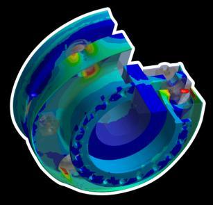
Highly Accurate and Robust Automotive Radar System Design. Markus Kopp Lead Application Specialist ANSYS Inc.
 Highly Accurate and Robust Automotive Radar System Design Markus Kopp Lead Application Specialist ANSYS Inc. Introduction This presentation is an overview of a proposed design methodology for automotive
TOP VIEW. Maxim Integrated Products 1
 19-2213; Rev 0; 10/01 Low-Jitter, Low-Noise LVDS General Description The is a low-voltage differential signaling (LVDS) repeater, which accepts a single LVDS input and duplicates the signal at a single
544 IEEE TRANSACTIONS ON ADVANCED PACKAGING, VOL. 31, NO. 3, AUGUST /$ IEEE
 544 IEEE TRANSACTIONS ON ADVANCED PACKAGING, VOL. 31, NO. 3, AUGUST 2008 Modeling and Measurement of Interlevel Electromagnetic Coupling and Fringing Effect in a Hierarchical Power Distribution Network
Microwave Coax. w w w. t e m p f l e x. c o m ( ) M i l f o r d R d. S o u t h G r a f t o n, M A
 M i l f o r d R d. S o u t h G r a f t o n, M A") Microwave Coax w w w. t e m p f l e x. c o m ( 5 0 8 ) 8 3 9-5 9 8 7 2 6 M i l f o r d R d. S o u t h G r a f t o n, M A 0 1 5 6 0 Microwave Coax Product Description Low Loss, Flexible Microwave products
Microwave Coax w w w. t e m p f l e x. c o m ( 5 0 8 ) 8 3 9-5 9 8 7 2 6 M i l f o r d R d. S o u t h G r a f t o n, M A 0 1 5 6 0 Microwave Coax Product Description Low Loss, Flexible Microwave products
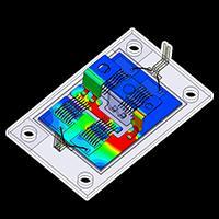
EMC Simulation of Consumer Electronic Devices
 of Consumer Electronic Devices By Andreas Barchanski Describing a workflow for the EMC simulation of a wireless router, using techniques that can be applied to a wide range of consumer electronic devices.
Probe Card Characterization in Time and Frequency Domain
 Gert Hohenwarter GateWave Northern, Inc. Probe Card Characterization in Time and Frequency Domain Company Logo 2007 San Diego, CA USA Objectives Illuminate differences between Time Domain (TD) and Frequency
Dual-Band Printed Inverted-F Antenna with a Nested Structure
 Progress In Electromagnetics Research Letters, Vol. 61, 1 6, 216 Dual-Band Printed Inverted-F Antenna with a Nested Structure Takuichi Hirano * and Junichi Takada Abstract A dual-band printed inverted-f
Transient calibration of electric field sensors
 Transient calibration of electric field sensors M D Judd University of Strathclyde Glasgow, UK Abstract An electric field sensor calibration system that operates in the time-domain is described and its
Design, Optimization, Fabrication, and Measurement of an Edge Coupled Filter
 SYRACUSE UNIVERSITY Design, Optimization, Fabrication, and Measurement of an Edge Coupled Filter Project 2 Colin Robinson Thomas Piwtorak Bashir Souid 12/08/2011 Abstract The design, optimization, fabrication,
Chapter 5 Electromagnetic interference in flash lamp pumped laser systems
 Chapter 5 Electromagnetic interference in flash lamp pumped laser systems This chapter presents the analysis and measurements of radiated near and far fields, and conducted emissions due to interconnects
9 Specifications. Specifications NOMINAL CHARACTERISTICS
 9 Specifications Specifications NOMINAL CHARACTERISTICS WARRANTED CHARACTERISTICS Nominal characteristics describe parameters and attributes that are guaranteed by design, but do not have associated tolerances.
EE290C - Spring 2004 Advanced Topics in Circuit Design
 EE290C - Spring 2004 Advanced Topics in Circuit Design Lecture #3 Measurements with VNA and TDR Ben Chia Tu-Th 4 5:30pm 531 Cory Agenda Relationships between time domain and frequency domain TDR Time Domain
EMC simulation addresses ECU validation issues
 EMC simulation addresses ECU validation issues A more straightforward validation of electromagnetic compatibility can be achieved by combining tools. By Stefan Heimburger, Andreas Barchanski, and Thorsten
Cu 0.37 Brass Cu 0.37 Brass
 To: From: EDGES MEMO #148 MASSACHUSETTS INSTITUTE OF TECHNOLOGY HAYSTACK OBSERVATORY WESTFORD, MASSACHUSETTS 01886 October 7, 2014 Telephone: 781-981-5400 Fax: 781-981-0590 EDGES Group Alan E.E. Rogers
A Millimeter Wave Center-SIW-Fed Antenna For 60 GHz Wireless Communication
 A Millimeter Wave Center-SIW-Fed Antenna For 60 GHz Wireless Communication M. Karami, M. Nofersti, M.S. Abrishamian, R.A. Sadeghzadeh Faculty of Electrical and Computer Engineering K. N. Toosi University
Documentation. PerfectPulse Fast Edge Signal Generator
 PerfectPulse Fast Edge Signal Generator Documentation Version 1.1, 2018 Copyright 2018 Picotest and PMK Mess- und Kommunikationstechnik GmbH All Rights Reserved Trademarks The Picotest logo is a trademark
Nonlinear Effects in Active Phased Array System Performance
 Nonlinear Effects in Active Phased Array System Performance Larry Williams, PhD Director of Product Management ANSYS Inc. 1 Advanced Simulation Simulate the Complete Product Real-life behavior in real-world
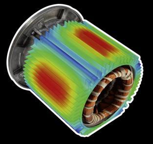
of sound radiation from electric motors
 Titelmasterformat Mid-frequency challenge durch Klicken efficient bearbeiten simulation of sound radiation from electric motors M. Moosrainer, M. Jegham, CADFEM GmbH 19.03.2018, DAGA 2018 Munich ANSYS
INSTRUCTION MANUAL TRI-PLATE LINE MODEL EM-7310
 INSTRUCTION MANUAL TRI-PLATE LINE MODEL EM-7310 INSTRUCTION MANUAL THIS INSTRUCTION MANUAL AND ITS ASSOCIATED INFORMATION IS PRO- PRIETARY. UNAUTHORIZED REPRO- DUCTION IS FORBIDDEN. 1998 ELECTRO-METRICS
Exercise 1-2. Velocity of Propagation EXERCISE OBJECTIVE
 Exercise 1-2 Velocity of Propagation EXERCISE OBJECTIVE Upon completion of this unit, you will know how to measure the velocity of propagation of a signal in a transmission line, using the step response
Clear & Clean Display Graphics. Greg Young
 Clear & Clean Display Graphics Greg Young greg.young@ipex-us.com SGC vs. Discrete TP: Provide a 2.7Gb/s Data Transfer Performance Comparison between Discrete Twisted Pair #34 Wire Construction and SGC40
SPECIFICATION AND PERFORMANCE CHARACTERISTICS SERIAL ATA CABLE ASSEMBLIES
 SPECIFICATION AND PERFORMANCE CHARACTERISTICS OF SERIAL ATA CABLE ASSEMBLIES CIRCUIT ASSEMBLY CORP. 18 THOMAS STREET, IRVINE, CA 92618-2777 Page No. 1 CONTENTS: 1.0 SCOPE.. 3 2.0 APPLICABLE DOCUMENTS 3
Field Instrument Cable. Electrical Noise
 Field Instrument Cable Electrical Noise 1 Electrical Noise Instrument Cables are Susceptible to 4 Types of Noise: Static Magnetic Cross-Talk Common Mode 2 Static Noise Static Noise is caused by an electric
Keysight Technologies Techniques for Advanced Cable Testing
 Keysight Technologies Techniques for Advanced Cable Testing Using FieldFox handheld analyzers Application Note Transmission lines are used to guide the flow of energy from one point to another. Line types
THE PROPAGATION OF PARTIAL DISCHARGE PULSES IN A HIGH VOLTAGE CABLE
 THE PROPAGATION OF PARTIAL DISCHARGE PULSES IN A HIGH VOLTAGE CABLE Z.Liu, B.T.Phung, T.R.Blackburn and R.E.James School of Electrical Engineering and Telecommuniications University of New South Wales
Waveguides. Metal Waveguides. Dielectric Waveguides
 Waveguides Waveguides, like transmission lines, are structures used to guide electromagnetic waves from point to point. However, the fundamental characteristics of waveguide and transmission line waves
High Speed Characterization Report
 QTH-030-01-L-D-A Mates with QSH-030-01-L-D-A Description: High Speed Ground Plane Header Board-to-Board, 0.5mm (.0197 ) Pitch, 5mm (.1969 ) Stack Height Samtec, Inc. 2005 All Rights Reserved Table of Contents
SPACEWIRE CABLE AND CONNECTOR VARIATIONS
 SPACEWIRE CABLE AND CONNECTOR VARIATIONS Shaune S. Allen NASA Goddard Space Flight Center, Greenbelt, MD, 20771 E-mail: Shaune.S.Allen@nasa.gov Page 1 SpaceWire Connector Issues Connector Specification
A SIMPLE METHOD TO COMPARE THE SENSITIVITY OF DIFFERENT AE SENSORS FOR TANK FLOOR TESTING
 A SIMPLE METHOD TO COMPARE THE SENSITIVITY OF DIFFERENT AE SENSORS FOR TANK FLOOR TESTING HARTMUT VALLEN, JOCHEN VALLEN and JENS FORKER Vallen-Systeme GmbH, 82057 Icking, Germany Abstract AE testing of
Charge-Sensing Particle Detector PN 2-CB-CDB-PCB
 Charge-Sensing Particle Detector PN 2-CB-CDB-PCB-001-011 Introduction The charge-sensing particle detector (CSPD, Figure 1) is a highly charge-sensitive device intended to detect molecular ions directly.
Absence of Insertion Loss Anti-Resonance In Shielded Pairs Having High Skew
 Absence of Insertion Loss Anti-Resonance In Shielded Pairs Having High Greg Vaupotic Principal Engineer Background Allegedly, within-pair skew causes resonances (actually anti-resonances) to be present
Test Report based on DIN EN ISO/IEC 17025: 2005
 Test Report based on DIN EN ISO/IEC 1725: 25 GHMT Type Approval 2 Connector Permanent Link, Copper, Class EA according ISO/IEC 1181-1 Ed.1. Document-no: P582a-18-E This Test Report with the measurements
PCB Routing Guidelines for Signal Integrity and Power Integrity
 PCB Routing Guidelines for Signal Integrity and Power Integrity Presentation by Chris Heard Orange County chapter meeting November 18, 2015 1 Agenda Insertion Loss 101 PCB Design Guidelines For SI Simulation
Research Article Embedded Spiral Microstrip Implantable Antenna
 Antennas and Propagation Volume 211, Article ID 919821, 6 pages doi:1.1155/211/919821 Research Article Embedded Spiral Microstrip Implantable Antenna Wei Huang 1 and Ahmed A. Kishk 2 1 Department of Electrical
Simulation of Plasma Antenna Parameters
 www.ijetmas.com May 216, Volume 4, Issue 5, ISSN 2349-4476 Simulation of Plasma Antenna Parameters Prince Kumar and Rajneesh Kumar Department of Physics, Dr. H S. Gour Central University, Sagar (M. P),
Amphenol Amphenol Taiwan Corporation Sheet 1 of 14
 Amphenol Amphenol Taiwan Corporation Sheet 1 of 14 Title: Part Number: Description: USB3.0 Connector Product Specification GSB34 / GSB35 series Micro Family, Receptacle, SMT, PCB mount Revisions Control
Measurement Notes. Note 61. November Windscreen Shield Monitoring Using a Spiral Transmission Line
 Measurement Notes Note 61 November 28 Windscreen Shield Monitoring Using a Spiral Transmission Line Everett G. Farr. W. Scott Bigelow, and Leland H. Bowen Farr Research, Inc. Carl E Baum University of
A MINIATURIZED INTERNAL WIDEBAND ANTENNA FOR WIRELESS USB DONGLE APPLICATION
 Progress In Electromagnetics Research Letters, Vol. 17, 67 74, 2010 A MINIATURIZED INTERNAL WIDEBAND ANTENNA FOR WIRELESS USB DONGLE APPLICATION J.-G. Gong, Y.-C. Jiao, Q. Li, J. Wang, and G. Zhao National
Designing external cabling for low EMI radiation A similar article was published in the December, 2004 issue of Planet Analog.
 HFTA-13.0 Rev.2; 05/08 Designing external cabling for low EMI radiation A similar article was published in the December, 2004 issue of Planet Analog. AVAILABLE Designing external cabling for low EMI radiation
FIBRE CHANNEL CONSORTIUM
 FIBRE CHANNEL CONSORTIUM FC-PI-2 Clause 9 Electrical Physical Layer Test Suite Version 0.21 Technical Document Last Updated: August 15, 2006 Fibre Channel Consortium Durham, NH 03824 Phone: +1-603-862-0701
10 GIGABIT ETHERNET CONSORTIUM
 10 GIGABIT ETHERNET CONSORTIUM Clause 54 10GBASE-CX4 PMD Test Suite Version 1.0 Technical Document Last Updated: 18 November 2003 10:13 AM 10Gigabit Ethernet Consortium 121 Technology Drive, Suite 2 Durham,
Electronic Switch TOE 9261
 Application No. 9261-001 Power and Signal Line Interruptions for Automotive Tests Electronic Switch TOE 9261 9261E-AN001_Rev00.doc R TOELLNER ELECTRONIC INSTRUMENTE GMBH Gahlenfeldstrasse 31, 58313 Herdecke,