R&S SMA100A Signal Generator Specifications
|
|
|
- Claribel Allen
- 6 years ago
- Views:
Transcription


1 SMA100A_dat-sw_en_ _cover.indd 1 Data Sheet R&S SMA100A Signal Generator Specifications Test & Measurement To buy, sell, rent or trade-in this product please click on the link below: :45:04
2 Version June 2013 CONTENTS Key features... 3 Definitions... 4 Specifications... 5 RF performance... 5 Frequency... 5 Frequency sweep... 5 Reference frequency... 6 Level... 6 Level sweep... 8 Spectral purity... 9 List mode Analog modulation Possible modulation types Simultaneous modulation Amplitude modulation Frequency modulation (R&S SMA-B20 or R&S SMA-B22 option) Chirped pulses (R&S SMA-B20 or R&S SMA-B22 option) Phase modulation (R&S SMA-B20 or R&S SMA-B22 option) Pulse modulation VOR modulation (R&S SMA-K25 option) ILS modulation (R&S SMA-K25 option) Marker beacon (MKR BCN) (R&S SMA-K25 option) ADF mode (R&S SMA-K25 option) DME modulation (R&S SMA-K26 option) DME analysis (R&S SMA-K26 option) Modulation sources Internal modulation generator Multifunction generator (R&S SMA-K24 option) LF frequency sweep Standard pulse generator High-performance pulse generator (R&S SMA-K23 option) Pulse train (R&S SMA-K27 option) Output for pulse generator signals Clock synthesizer (R&S SMA-B29 option) R&S NRP-Z power analysis (R&S SMA-K28 option) Overview of power sensor functionalities Remote control Connectors Front-panel connectors Rear-panel connectors General data Ordering information License information Rohde & Schwarz R&S SMA100A Signal Generator
3 Version 06.01, June 2013 Key features Excellent signal quality Very low SSB phase noise of typ. 134 dbc (20 khz carrier offset, f = 1 GHz, 1 Hz measurement bandwidth), typ dbc with the enhanced phase noise performance option (R&S SMA-B22) Wideband noise of 162 dbc (meas.) with carrier offset > 40 MHz, f = 1 GHz, level = 9 dbm, 1 Hz measurement bandwidth Nonharmonics of < 96 dbc (carrier offset > 10 khz, f < 750 MHz, with the R&S SMA-B22 option) High-stability reference oscillator as standard Very low phase noise at low frequencies due to internal division of the fundamental frequency range (750 MHz to 1500 MHz) down to 6.6 MHz Ideal for use in production Very short frequency/level setting times of < 1.5 ms/1 ms (meas.) across the entire frequency and level range, < 450 µs in List mode Fast Hopping mode with flexibly addressable frequency and level pairs, as fast as normal List mode Frequency setting time of typ. < 10 µs within a bandwidth of up to 80 MHz due to direct access to the DDS-based synthesizer (with the R&S SMA-B20 or -B22 option; FM EXTERNAL DIGITAL mode) Very high level accuracy and repeatability High output power of up to +18 dbm, overrange up to +28 dbm Electronic attenuator with built-in overvoltage protection over entire frequency range Minimum space requirements due to compact size (only two height units) Aerospace and defense applications Pulse modulator with excellent characteristics (on/off ratio of > 100 db (meas.) for f < 5.5 GHz, rise/fall time typ. < 7 ns) Pulse generator integrated as standard Optional high-performance pulse generator with minimum pulse width of 10 ns (R&S SMA-K23) Optional generation of versatile pulse sequences/pulse trains (R&S SMA-K27) Optional chirp modulation (R&S SMA-B20 or R&S SMA-B22) Optional VOR/ILS modulation (R&S SMA-K25) Optional DME modulation/analysis (R&S SMA-K26) Optional operating altitude up to 4600 m (R&S SMA-B46) Optional removable mass storage (CompactFlash card, R&S SMA-B80) All-purpose instrument Frequency range of 9 khz to 3 GHz (R&S SMA-B103/R&S SMA-B103L) or 6 GHz (R&S SMA-B106/R&S SMA-B106L) Frequency, level and LF sweeps Phase-continuous frequency setting AM, broadband FM/φM (R&S SMA-B20 or R&S SMA-B22), pulse modulation Built-in LF generator up to 1 MHz, optional multifunction generator (R&S SMA-K24) up to 10 MHz Optional low-jitter clock synthesizer up to 1.5 GHz (R&S SMA-B29) Power measurement using R&S NRP-Zxx power sensors Optional power analysis (R&S SMA-K28) using R&S NRP-Zxx power sensors for scalar network analysis or automatic pulse parameter measurement Intuitive operating concept and versatile interfaces Color display with pixels Intuitive user interface with graphical display of signal flow (block diagram) Context-sensitive online help Remote control via GPIB, LAN or USB Selectable control language (SCPI or remote control emulation of various signal generators) Remote operation by browser (or VNC client) USB connectors (e.g. for keyboard, mouse, memory stick) Support of R&S NRP-Zxx power sensors for precise power measurements Rohde & Schwarz R&S SMA100A Signal Generator 3

4 Version June 2013 Definitions General Product data applies under the following conditions: Three hours storage at ambient temperature followed by 30 minutes warm-up operation Specified environmental conditions met Recommended calibration interval adhered to All internal automatic adjustments performed, if applicable Level within specified level range Specifications with limits Represent warranted product performance by means of a range of values for the specified parameter. These specifications are marked with limiting symbols such as <,, >,, ±, or descriptions such as maximum, limit of, minimum. Compliance is ensured by testing or is derived from the design. Test limits are narrowed by guard bands to take into account measurement uncertainties, drift and aging, if applicable. Specifications without limits Represent warranted product performance for the specified parameter. These specifications are not specially marked and represent values with no or negligible deviations from the given value (e.g. dimensions or resolution of a setting parameter). Compliance is ensured by design. Typical data (typ.) Characterizes product performance by means of representative information for the given parameter. When marked with <, > or as a range, it represents the performance met by approximately 80 % of the instruments at production time. Otherwise, it represents the mean value. Nominal values (nom.) Characterize product performance by means of a representative value for the given parameter (e.g. nominal impedance). In contrast to typical data, a statistical evaluation does not take place and the parameter is not tested during production. Measured values (meas.) Characterize expected product performance by means of measurement results gained from individual samples. Uncertainties Represent limits of measurement uncertainty for a given measurand. Uncertainty is defined with a coverage factor of 2 and has been calculated in line with the rules of the Guide to the Expression of Uncertainty in Measurement (GUM), taking into account environmental conditions, aging, wear and tear. Typical data as well as nominal and measured values are not warranted by Rohde & Schwarz. 4 Rohde & Schwarz R&S SMA100A Signal Generator
5 Version 06.01, June 2013 Specifications Specifications only valid for levels within specified level range. RF performance Frequency Range R&S SMA-B103/-B103L 9 khz to 3 GHz R&S SMA-B106/-B106L 9 khz to 6 GHz Resolution of setting 0.01 Hz Resolution of synthesis fundamental frequency range 750 MHz to 1500 MHz standard 5 µhz (nom.) with R&S SMA-B22 option 0.2 µhz (nom.) Setting time to within < for f > 6.6 MHz or < 35 Hz for f < 6.6 MHz no relay switchover after IEC/IEEE bus delimiter < 2 ms in ALC OFF S&H mode < 5 ms after trigger pulse in List mode or Fast Hopping mode < 450 µs Resolution of phase offset setting adjustable in 0.1 steps Multiplier for phase-continuous frequency f 6.6 MHz rm = 1/2 setting 6.6 MHz < f MHz rm = 1/ MHz < f MHz rm = 1/ MHz < f MHz rm = 1/ MHz < f MHz rm = 1/ MHz < f MHz rm = 1/ MHz < f 375 MHz rm = 1/4 375 MHz < f 750 MHz rm = 1/2 750 MHz < f 1500 MHz rm = MHz < f 3 GHz rm = 2 f > 3 GHz rm = 4 Phase-continuous frequency setting range rm 1 MHz (nom.) with R&S SMA-B22 option narrow mode wide mode rm 5 MHz rm 20 MHz Max. phase-continuous frequency step rm 2 khz (nom.) with R&S SMA-B22 option rm 100 khz (nom.) Frequency sweep Operating mode digital sweep in discrete steps Trigger modes execute sweep continuously with internal auto trigger source execute one full sweep single execute one step step sweep start and stop controlled by start/stop external trigger signal Trigger source internal timer external external trigger signal (INST TRIG at rear), rotary knob, remote control Trigger slope external trigger signal positive, negative Sweep range full frequency range Sweep shape sawtooth, triangle Step size linear full frequency range logarithmic 0.01 % to 100 % per step Dwell time setting range 10 ms to 10 s Dwell time setting resolution 0.1 ms Rohde & Schwarz R&S SMA100A Signal Generator 5
6 Version June 2013 Reference frequency Frequency error at time of calibration in production < with R&S SMA-B22 option < Aging after 10 days of uninterrupted operation /day, /year with R&S SMA-B22 option /day, /year Maximum temperature effect in temperature range 0 C to +50 C ± with R&S SMA-B22 option ± Warm-up time to nominal thermostat temperature 10 min Output for internal reference frequnecy Connector type REF OUT on rear panel BNC female Output frequency sine wave 10 MHz or external input frequency Output level 2 dbm to 8 dbm 5 dbm to 7 dbm (typ.) Source impedance 50 Ω (nom.) Input for external reference frequency Connector type REF IN on rear panel BNC female Input frequency 5 MHz, 10 MHz or 13 MHz Min. frequency locking range ± with R&S SMA-B22 option ± Input level range level limits 6 dbm, 19 dbm recommended input level 0 dbm to 19 dbm Input impedance 50 Ω (nom.) Input for electronic tuning of internal reference frequency Connector type EXT TUNE on rear panel BNC female Sensitivity /V to /V /V to /V (typ.) with R&S SMA-B22 option /V to /V /V to /V (typ.) Input voltage 10 V to +10 V Input impedance 10 kω (nom.) with R&S SMA-B22 option 5 kω (nom.) Level The R&S SMA100A has three different modes for level setting: NORMAL mode: In this mode, the attenuator switches without wear and tear due to the exclusive use of electronic switches. The maximum specified level depends on the set frequency (see table below). HIGH POWER mode: In this mode, the electronic attenuator is bypassed with mechanical relays for high output power (up to typ. 28 dbm overrange). The relays are not switched over in this mode. The typical minimum level is 11 dbm. AUTO mode: In this mode, the mechanical relay bypass is switched automatically if the set level is higher than the specified max. level in the NORMAL mode. The output level is specified over the full range from 120 dbm up to +18 dbm (+15 dbm for R&S SMA-B106). The R&S SMA100A is also available without attenuator (R&S SMA-B103L and R&S SMA-B106L) options. Setting range Specified level range with R&S SMA-B103/-B106 frequency option Specified level range with R&S SMA-B103L/-B106L frequency option Resolution of setting with electronic attenuator (R&S SMA-B103/-B106 option) 145 dbm to +30 dbm without attenuator (R&S SMA-B103L/-B106L option) 20 dbm to +30 dbm NORMAL mode 100 khz < f 200 khz 120 dbm to +11 dbm (PEP) khz < f 3 GHz 120 dbm to +13 dbm (PEP) f > 3 GHz 120 dbm to +9 dbm (PEP) AUTO mode 100 khz < f 30 MHz 120 dbm to +16 dbm (PEP) 30 MHz < f 3 GHz 120 dbm to +18 dbm (PEP) f > 3 GHz 120 dbm to +15 dbm (PEP) AUTO mode 100 khz < f 30 MHz +12 dbm to +17 dbm (PEP) 30 MHz < f 3 GHz +12 dbm to +19 dbm (PEP) f > 3 GHz +10 dbm to +17 dbm (PEP) 0.01 db (nom.) 1 PEP = peak envelope power. 6 Rohde & Schwarz R&S SMA100A Signal Generator
7 Version 06.01, June 2013 Level error Additional level error with ALC OFF S&H Output impedance VSWR in 50 Ω system with R&S SMA-B103/-B106 frequency option Output impedance VSWR in 50 Ω system with R&S SMA-B103L/-B106L frequency option Setting time Interruption-free level setting range Reverse power (from 50 Ω source) ALC state ON, attenuator mode AUTO, temperature range +18 C to +33 C 100 khz < f 3 GHz < 0.5 db f > 3 GHz < 0.9 db after search once and under stable temperature conditions < 0.3 db NORMAL mode, ALC state ON 6.6 MHz < f 3 GHz < 1.65 f > 3 GHz < 1.9 HIGH POWER mode, ALC state ON 6.6 MHz < f 3 GHz < 1.75 f > 3 GHz < 1.9 without attenuator, ALC state ON 6.6 MHz < f 3 GHz < 1.9 f > 3 GHz < 2.3 with GUI update stopped, attenuator mode AUTO, temperature range +18 C to +33 C to < 0.1 db deviation from final value, no relay switchover ALC state ON, after IEC/IEEE bus delimiter < 1.5 ms ALC state OFF, after IEC/IEEE bus delimiter < 5 ms in List mode or Fast Hopping mode, after trigger impulse, f > 6.6 MHz < 450 µs to < 0.3 db deviation from final value, relay switchover in attenuator mode AUTO after IEC/IEEE bus delimiter < 10 ms with attenuator mode FIXED, > 20 db ALC state ON maximum permissible RF power in output frequency range of RF path for f > 1 MHz with R&S SMA-B103/-B106 option 1 MHz < f 3 GHz 50 W 3 GHz < f < 6 GHz 10 W with R&S SMA-B103L/-B106L option 0.05 W Maximum permissible DC voltage with R&S SMA-B103/-B106 option 50 V with R&S SMA-B103L/-B106L option 5 V Level / dbm Carrier frequency / GHz Maximum available power, attenuator mode NORMAL (lower trace) or HIGH POWER (center trace) and without attenuator (upper trace). Rohde & Schwarz R&S SMA100A Signal Generator 7
8 Version June List mode ALC On ALC Off S&H Occurrence Setting time / ms Histogram of level setting times for different ALC states and List mode (meas.). Level sweep Level / dbm RF level Ambient temperature :0 0 18:00 00:0 0 06:0 0 12:00 18:00 00:00 06:00 12:00 18:00 00:00 06:00 Time R&S SMA100A level repeatability at 2.1 GHz, 0 dbm, ALC ON. Operating mode digital sweep in discrete steps Trigger modes execute sweep continuously with internal auto trigger source execute one full sweep single execute one step step sweep start and stop controlled by start/stop external trigger signal Trigger source internal timer external external trigger signal (INST TRIG at rear), rotary knob, remote control Trigger slope external trigger signal positive, negative Sweep range with R&S SMA-B103/-B106 option, attenuator mode AUTO level range of attenuator modes NORMAL or HIGH POWER The relay switching threshold (= maximum specified level of attenuator mode NORMAL) must not be exceeded during a sweep. with R&S SMA-B103L/-B106L option full level range interruption-free level sweep with 0.01 db to 30 db attenuator mode FIXED Sweep shape sawtooth, triangle Step size setting resolution 0.01 db Dwell time setting range 10 ms to 10 s Dwell time setting resolution 0.1 ms Temperature / C 8 Rohde & Schwarz R&S SMA100A Signal Generator
9 Version 06.01, June 2013 Spectral purity Harmonics for f > 1 MHz, CW with R&S SMA-B103/-B106 AUTO/NORMAL mode, level 9 dbm < 30 dbc HIGH POWER mode, level 14 dbm < 30 dbc with R&S SMA-B103L/-B106L level 15 dbm < 30 dbc Nonharmonics CW, level > 10 dbm carrier offset > 10 khz f 1500 MHz < 80 dbc 1500 MHz < f 3 GHz < 74 dbc f > 3 GHz < 68 dbc carrier offset > 850 khz f 1500 MHz < 86 dbc 1500 MHz < f 3 GHz < 80 dbc f > 3 GHz < 74 dbc Nonharmonics with R&S SMA-B22 option CW, level > 10 dbm carrier offset > 10 khz f 750 MHz < 96 dbc 750 MHz < f 1500 MHz < 90 dbc 1500 MHz < f 3 GHz < 84 dbc f > 3 GHz < 78 dbc Subharmonics f 1500 MHz none f > 1500 MHz < 74 dbc Wideband noise attenuator mode AUTO, for level > 10 dbm with R&S SMA-B10xL, for level > 5 dbm with R&S SMA-B10x, carrier offset > 10 MHz, measurement bandwidth 1 Hz, CW 9 khz f 6.6 MHz < 147 dbc 6.6 MHz < f 750 MHz < 152 dbc 750 MHz < f 1500 MHz < 153 dbc 1.5 GHz < f 3 GHz < 150 dbc f > 3 GHz < 148 dbc SSB phase noise CW, carrier offset 20 khz, measurement bandwidth 1 Hz f 6.6 MHz 147 dbc (meas.) f = 100 MHz < 147 dbc, 153 dbc (typ.) f = 1 GHz < 131 dbc, 134 dbc (typ.) f = 2 GHz < 125 dbc, 128 dbc (typ.) f = 3 GHz < 121 dbc, dbc (typ.) f = 4 GHz < 119 dbc, 121 dbc (typ.) f = 6 GHz < 115 dbc, 118 dbc (typ.) SSB phase noise with R&S SMA-B22 option CW, carrier offset 20 khz, measurement bandwidth 1 Hz f 6.6 MHz f = 100 MHz f = 1 GHz f = 2 GHz f = 3 GHz f = 4 GHz f = 6 GHz 151 dbc (meas.) < 151 dbc, dbc (typ.) < 136 dbc, dbc (typ.) < 130 dbc, 133 dbc (typ.) < 126 dbc, dbc (typ.) < 123 dbc, 127 dbc (typ.) < 120 dbc, 124 dbc (typ.) RMS jitter f = 1 GHz BW = 1 Hz to 10 MHz 430 fs (430 µui) (meas.) f = 155 MHz BW = 100 Hz to 1.5 MHz 60 fs (9 µui) (meas.) f = 622 MHz BW = 1 khz to 5 MHz 36 fs (22 µui) (meas.) f = GHz BW = 5 khz to 15 MHz 22 fs (55 µui) (meas.) RMS jitter with R&S SMA-B22 option f = 1 GHz BW = 1 Hz to 10 MHz 72 fs (72 µui) (meas.) f = 155 MHz BW = 100 Hz to 1.5 MHz 25 fs (3.8 µui) (meas.) f = 622 MHz BW = 1 khz to 5 MHz 21 fs (13 µui) (meas.) f = GHz BW = 5 khz to 15 MHz 19 fs (47 µui) (meas.) Rohde & Schwarz R&S SMA100A Signal Generator 9
10 Version June 2013 Residual FM Residual AM RMS value at f = 1 GHz 0.3 khz to 3 khz, weighted (ITU-T) < 1 Hz 0.03 khz to 23 khz < 4 Hz level = 0 dbm RMS value (0.03 khz to 20 khz) < 0.02 % 30 Harmonics / dbc Harmonic 2f Harmonic 3f Carrier frequency / GHz Measured harmonics at +9 dbm versus carrier frequency (level mode AUTO) Harmonic 2f Harmonics / dbc Harmonic 3f Carrier frequency / GHz Measured harmonics at +18 dbm versus carrier frequency (level mode AUTO). 120 Wideband noise / dbc (1 Hz) Carrier frequency / GHz Wideband noise at 40 MHz offset and +9 dbm versus carrier frequency measured with the R&S FSQ8 signal and spectrum analyzer. 10 Rohde & Schwarz R&S SMA100A Signal Generator
11 Version 06.01, June 2013 SSB phase noise / dbc (1 Hz) GHz 3 GHz 1 GHz 100 MHz 10 MHz k 10k 100k 1M 10M Offset frequency / Hz Measured SSB phase noise with internal reference oscillator (standard instrument). SSB phase noise / dbc (1 Hz) GHz 3 GHz 1 GHz 100 MHz 10 MHz k 10k 100k 1M 10M Offset frequency / Hz Measured SSB phase noise with internal reference oscillator (with R&S SMA-B22 enhanced phase noise performance and FM/φM modulator option). SSB phase noise / dbc (1 Hz) Standard performance Enhanced phase noise performance with B22 option k 10k 100k 1M 10M Offset frequency / Hz Measured SSB phase noise, f = 1 GHz, comparison of standard performance and performance with R&S SMA-B22 option. Rohde & Schwarz R&S SMA100A Signal Generator 11
12 Version June 2013 Carrier frequency in MHz measured phase noise in dbc (1 Hz) with R&S SMA-B22 option frequency offset from carrier 1 Hz 10 Hz 100 Hz 1 khz 10 khz 100 khz 1 MHz 10 MHz 0.1 to to to to to to to to to to to to to to to to to to to AM noise / dbc (1Hz) Standard performance AM noise performance with B22 option k 10k 100k 1M 10M Offset frequency / Hz Measured AM noise, f = 1 GHz, level = +14 dbm, ALC ON, comparison of standard performance and performance with R&S SMA-B22 option. 12 Rohde & Schwarz R&S SMA100A Signal Generator
13 Version 06.01, June 2013 List mode Frequency and level values can be stored in a list and set in an extremely short amount of time. Trigger modes execute list continuously with internal auto trigger source execute list once single execute one step step use of addressable frequency/level pairs (Fast Hopping mode) with immediate internal trigger external hop, direct with external trigger external hop Trigger source internal timer external external trigger signal (INST TRIG at rear), rotary knob, remote control, fast hopping bus Trigger slope external trigger signal positive, negative Max. number of stored settings 2000 Dwell time setting range 1 ms to 1 s Dwell time setting resolution 0.1 ms Setting time after external trigger see frequency and level data Analog modulation Possible modulation types Amplitude modulation, frequency modulation, phase modulation, pulse modulation, chirped pulses, avionics modulation (DME, VOR, ILS, MKR BCN, ADF). Simultaneous modulation Amplitude modulation Frequency modulation Phase modulation Pulse modulation DME modulation Amplitude modulation + + (+) (+) Frequency modulation + + Phase modulation + + Pulse modulation (+) = compatible, (+) = compatible with limitations, = incompatible. With chirped pulses and certain types of avionics modulation (VOR, ILS, MKR BCN, ADF), simultaneous modulation is not possible. Amplitude modulation For f 100 khz, attenuator mode AUTO, level (PEP) 1 within specified level range. Modulation source internal, external, internal + external External coupling AC, DC AM depth setting range At high levels, modulation is clipped when the maximum PEP is reached. 0 % to 100 % Resolution of setting 0.1 % AM depth (m) error f mod = 1 khz and m < 80 % < (3 % of reading + 1 %) AM distortion f mod = 1 khz m = 30 % < 1 % m = 80 % < 2 % Modulation frequency response m = 60 %, up to 100 khz < 3 db Incidental φm at AM m = 30 %, f mod = 1 khz, ±peak/2 < 0.1 rad Rohde & Schwarz R&S SMA100A Signal Generator 13
14 Version June 2013 Frequency modulation (R&S SMA-B20 or R&S SMA-B22 option) FM multiplier (rm) for different frequency f MHz rm = 1/2 (all modes except LOW NOISE) ranges f 6.6 MHz rm = 1/2 (only in LOW NOISE mode) 6.6 MHz < f MHz rm = 1/128 (only in LOW NOISE mode) MHz < f MHz rm = 1/64 (only in LOW NOISE mode) MHz < f MHz rm = 1/32 (only in LOW NOISE mode) MHz < f MHz rm = 1/ MHz < f MHz rm = 1/ MHz < f 375 MHz rm = 1/4 375 MHz < f 750 MHz rm = 1/2 750 MHz < f 1500 MHz rm = MHz < f 3 GHz rm = 2 f > 3 GHz rm = 4 Modulation source internal, external, internal + external, external digital External coupling AC, DC Operating modes FM mode NORMAL with R&S SMA-B22 option FM mode NORMAL FM mode LOW NOISE Maximum deviation FM mode NORMAL rm 10 MHz FM mode LOW NOISE rm 100 khz Resolution of setting < 0.02 % of set deviation min. rm 0.1 Hz FM deviation error f mod = 10 khz, deviation half of max. deviation internal < (1.5 % of reading + 20 Hz) external, high input impedance < (2 % of reading + 20 Hz) FM distortion f mod = 10 khz, deviation = rm 1 MHz < 0.1 % Modulation frequency response FM mode NORMAL (DC/AC coupling), 50 Ω input impedance DC/10 Hz to 100 khz < 0.5 db DC/10 Hz to 10 MHz < 3 db FM mode LOW NOISE (DC/AC coupling), 50 Ω input impedance DC/10 Hz to 100 khz < 3 db Synchronous AM with FM 40 khz deviation, f mod = 1 khz f > 5 MHz < 0.1 % f > 3 GHz < 0.2 % Carrier frequency offset with FM DC after FM offset calibration 50 Ω input impedance < 0.2 % of set deviation 14 Rohde & Schwarz R&S SMA100A Signal Generator
15 Version 06.01, June 2013 Chirped pulses (R&S SMA-B20 or R&S SMA-B22 option) The R&S SMA100A always uses chirp modulation together with pulse modulation. When chirp modulation is activated, the ALC state of the instrument is automatically changed to ALC OFF (sample & hold). In this state, the ALC loop is opened and the output level is set directly. In order to set the correct output level, a sample & hold measurement is performed after each frequency or level setting. In the following cases, the nominal ON level is present for nominally 3 ms to 5 ms during a sample & hold measurement after level or frequency setting: No attenuator is installed (R&S SMA-B103L/R&S SMA-B106L frequency option) In HIGH POWER mode In AUTO mode if the level is in the high power range, i.e. the mechanical relay bypass is switched Otherwise, the level is decreased by 30 db during a sample & hold measurement. Chirp bandwidth multiplier (rm) for different frequency ranges Modulation source Trigger modes f MHz rm = 1/ MHz < f MHz rm = 1/ MHz < f MHz rm = 1/ MHz < f 375 MHz rm = 1/4 375 MHz < f 750 MHz rm = 1/2 750 MHz < f 1500 MHz rm = MHz < f 3 GHz rm = 2 f > 3 GHz rm = 4 pulse modulation internal pulse generator frequency modulation (linear) internal modulation generator continuous trigger with internal trigger auto source externally triggered externally gated Trigger slope external trigger signal positive, negative Gate polarity external gate signal normal, inverse Input impedance external trigger/gate signal 50 Ω, 10 kω (nom.) Chirp direction up, down Maximum bandwidth rm 20 MHz Pulse period setting range 5 µs to 100 s with R&S SMA-K23 option 1.1 µs to 100 s Pulse width setting range 2 µs to 100 s pulse width < (pulse period 1 µs) with R&S SMA-K23 option 100 ns to 100 s pulse width < (pulse period 1 µs) Pulse parameter setting resolution 1 µs with R&S SMA-K23 option 20 ns Maximum chirp rate rm 10 MHz/µs (nom.) Rohde & Schwarz R&S SMA100A Signal Generator 15
16 Version June 2013 Phase modulation (R&S SMA-B20 or R&S SMA-B22 option) φm multiplier (rm) for different frequency f MHz rm = 1/2 (all modes except LOW NOISE) ranges f 6.6 MHz rm = 1/2 (only in LOW NOISE mode) 6.6 MHz < f MHz rm = 1/128 (only in LOW NOISE mode) MHz < f MHz rm = 1/64 (only in LOW NOISE mode) MHz < f MHz rm = 1/32 (only in LOW NOISE mode) MHz < f MHz rm = 1/ MHz < f MHz rm = 1/ MHz < f 375 MHz rm = 1/4 375 MHz < f 750 MHz rm = 1/2 750 MHz < f 1500 MHz rm = MHz < f 3 GHz rm = 2 f > 3 GHz rm = 4 Modulation source internal, external, internal + external, external digital External coupling AC, DC Operating modes φm mode HIGH DEVIATION, φm mode HIGH BANDWIDTH with R&S SMA-B22 option φm mode HIGH DEVIATION, φm mode HIGH BANDWIDTH φm mode LOW NOISE Maximum deviation φm mode LOW NOISE rm 0.25 rad φm mode HIGH DEVIATION rm 20 rad φm mode HIGH BANDWIDTH rm 1 rad Resolution of setting φm mode LOW NOISE/HIGH DEVIATION < 0.02 % of set deviation, min. rm 20 µrad φm mode HIGH BANDWIDTH < 0.1 % of set deviation, min. rm 20 µrad φm deviation error f mod = 10 khz, deviation half of max. deviation internal < (1.5 % of reading rad) external, high input impedance < (2 % of reading rad) φm distortion f mod = 10 khz, half of max. deviation < 0.2 %, < 0.1 % (typ.) Modulation frequency response φm mode HIGH DEVIATION (DC/AC coupling), 50 Ω input impedance deviation rm 5 rad DC/10 Hz to 500 khz < 1 db deviation > rm 5 rad DC/10 Hz to 10 khz < 1 db φm mode HIGH BANDWIDTH (DC/AC coupling), 50 Ω input impedance DC/10 Hz to 100 khz < 0.5 db DC/10 Hz to 10 MHz < 3 db φm mode LOW NOISE (DC/AC coupling), 50 Ω input impedance DC/10 Hz to 100 khz < 3 db Pulse modulation When pulse modulation is activated, the ALC state of the R&S SMA100A is automatically changed to ALC OFF (sample & hold). In this state, the ALC loop is opened and the output level is set directly. In order to set the correct output level, a sample & hold measurement is performed after each frequency or level setting. In the following cases, the nominal ON level is present for nominally 3 ms to 5 ms during a sample & hold measurement after level or frequency setting: No attenuator is installed (R&S SMA-B103L/R&S SMA-B106L frequency option) In HIGH POWER mode In AUTO mode if the level is in the high power range, i.e. the mechanical relay bypass is switched Otherwise, the level is decreased by 30 db during a sample & hold measurement. Modulation source On/off ratio Rise/fall time Pulse repetition frequency Video crosstalk f > 180 MHz 10 %/90 % of RF amplitude spectral line of fundamental of 100 khz square-wave modulation external, internal > 80 db < 20 ns, < 7 ns (typ.) 0 Hz to 10 MHz < 30 dbc 16 Rohde & Schwarz R&S SMA100A Signal Generator
17 Version 06.01, June 2013 VOR modulation (R&S SMA-K25 option) Attenuator mode AUTO, level (PEP) 1 within specified level range. VOR specification valid for carrier frequency range from 108 MHz to 118 MHz. VOR operating modes generation of VOR signal NORM 30 Hz VAR tone VAR 9.96 khz carrier, unmodulated subcarrier 9.96 khz carrier, modulated subcarrier + FM Modulation tones Frequency error 30 Hz (VAR, REF) < (0.005 Hz + relative deviation of reference frequency 30 Hz) Frequency setting range 30 Hz REF 10 Hz to 60 Hz 9.96 khz FM carrier 5 khz to 15 khz COM/ID tone 0.1 Hz to 20 khz Frequency setting resolution 0.1 Hz FM deviation setting range 9.96 khz FM carrier 0 Hz to 960 Hz FM deviation setting resolution 9.96 khz FM carrier 1 Hz FM deviation error 9.96 khz FM carrier at 480 Hz deviation < 1 Hz External AM tone input connector AM EXT Modulation depth Sum of modulation depths of 30 Hz (VAR) signal, 9.96 khz FM carrier, COM/ID and external AM signal must not exceed 100 %. AM depth setting range 0 % to 100 % AM depth setting resolution 0.1 % AM depth error 30 Hz (VAR, REF), 30 % AM depth < 0.5 % AM depth 9.96 khz FM carrier, 30 % AM depth < 0.5 % AM depth COM/ID, tone = 1020 Hz, depth = 10 % < 0.5 % AM depth External AM tone sensitivity 0.01 V/% Bearing angle Setting range 0 to 360 default setting 0.00 Setting resolution 0.01 Error < 0.05 ILS modulation (R&S SMA-K25 option) Attenuator mode AUTO, level (PEP) 1 within specified level range. ILS-LOC specification valid for carrier frequency range from 108 MHz to 118 MHz. ILS-GS specification valid for carrier frequency range from 329 MHz to 335 MHz. ILS modulation generation of ILS localizer signal, ILS-LOC COM/ID tone possible generation of ILS glideslope signal ILS-GS ILS operating modes NORM 90 Hz Hz + COM/ID tone (ILS-LOC) 90 Hz suppression of 150 Hz modulation tone 150 Hz suppression of 90 Hz modulation tone ILS modulation tones If the frequency of the 90 Hz or 150 Hz tone is varied, the other tone is automatically changed in proportion. Frequency error < (0.02 Hz + relative deviation of reference frequency ILS tone frequency) Frequency setting range 90 Hz tone 60 Hz to 120 Hz 150 Hz tone 100 Hz to 200 Hz COM/ID tone 0.1 Hz to 20 khz Frequency setting resolution 90 Hz tone 0.3 Hz 150 Hz tone 0.5 Hz COM/ID tone 0.1 Hz External AM tone input connector AM EXT Modulation depth Sum of modulation depths of 90 Hz, 150 Hz, COM/ID and external AM signal must not exceed 100 %. Setting range SDM of 90 Hz, 150 Hz, COM/ID tone 0 % to 100 % ILS-LOC default setting 40 % ILS-GS default setting 80 % Setting resolution SDM and COM/ID depth 0.1 % AM depth error SDM = 40 % < 0.8 % AM depth SDM = 80 % < 1.6 % AM depth COM/ID, tone = 1020 Hz, depth = 10 % < 0.5 % AM depth External AM tone sensitivity 0.01 V/% Rohde & Schwarz R&S SMA100A Signal Generator 17
18 Version June 2013 Difference in depth of modulation (DDM) Setting range 0 to ±SDM Setting resolution Error < % of DDM reading ILS phase Setting range 0 to 120 Setting resolution 0.01 Error < 0.05 Marker beacon (MKR BCN) (R&S SMA-K25 option) Attenuator mode AUTO, level (PEP) within specified level range. MKR-BCN specification valid for carrier frequency range from 74 MHz to 76 MHz. Modulation tones Frequency error Marker frequencies COM/ID tone frequency setting range COM/ID tone frequency setting resolution Modulation depth Sum of modulation depths of marker tone and COM/ID signal must not exceed 100 %. AM depth setting range 0 % to 100 % marker tone default setting 95 % AM depth setting resolution 0.1 % AM depth error marker tone, depth = 95 % < 4 % AM depth COM/ID, tone = 1020 Hz, depth = 10 % < 0.5 % AM depth ADF mode (R&S SMA-K25 option) The ADF mode provides a carrier frequency of 190 khz with 30 % AM depth at 1 khz modulation rate. < (0.005 Hz + relative deviation of reference frequency marker frequency) 400 Hz, 1300 Hz and 3000 Hz 0.1 Hz to 20 khz 0.1 Hz Frequency error ADF tone < (0.005 Hz + relative deviation of reference frequency ADF frequency) ADF frequency setting range 0.1 Hz to 20 khz ADF setting resolution 0.1 Hz AM depth setting range 0 % to 100 % AM depth setting resolution 0.1 % ADF tone default setting 30 % 18 Rohde & Schwarz R&S SMA100A Signal Generator
19 Version 06.01, June 2013 DME modulation (R&S SMA-K26 option) Specifications valid for carrier frequency range from 960 MHz to 1215 MHz, attenuator mode AUTO, ALC state AUTO, level (PEP) within specified level range and DME default settings. When DME modulation is activated, the ALC state of the R&S SMA100A is automatically changed to sample & hold. In this state, the ALC loop is opened and the output level is set directly. In order to set the correct output level, a sample & hold measurement is executed after each frequency or level setting. In the following cases, the nominal ON level is present for typ. 3 ms to 5 ms after level or frequency setting: No attenuator is installed (R&S SMA-B103L/R&S SMA-B106L frequency option) In HIGH POWER mode In AUTO mode if the level is in the high power range, i.e. the mechanical relay bypass is switched Otherwise, the level is decreased by 30 db during a sample & hold measurement. DME operating modes DME/N DME interrogation DME reply DME channel X, Y Single pulse generation of a single pulse instead of a ON, OFF pulse pair Squitter pulses randomly distributed pulse repetition rate ON, OFF in line with EUROCAE ED-54 Level error attenuator mode AUTO, temperature range +18 C to +33 C pulse peak power error < 0.8 db pulse-to-pulse level difference < 0.2 db, < 0.1 db (typ.) On/off ratio > 80 db Pulse shaping cos² shape for rising and falling edge cos² cos shape for rising edge; cos cos² cos² shape for falling edge linear shape for rising and falling edge linear Pulse rise/fall time setting range 10 %/90 % of RF amplitude 0.5 µs to 20 µs Pulse width setting range 50 %/50 % of RF amplitude 1 µs to 100 µs Pulse spacing setting range 50 %/50 % of RF amplitude 1 µs to 100 µs Pulse parameter setting resolution rise/fall time, pulse width, pulse spacing 20 ns Rise/fall time error rise/fall time = 2 µs < 150 ns, < 70 ns (typ.) Pulse width error pulse width = 3.5 µs < 150 ns, < 70 ns (typ.) Pulse spacing error pulse spacing = 12 µs or 36 µs < 100 ns, < 40 ns (typ.) Pulse repetition rate setting range squitter OFF 10 pp/s to 6000 pp/s 2 squitter ON (mean pulse repetition rate) 10 pp/s to 6000 pp/s (nom.) Pulse repetition rate setting resolution squitter OFF 1 pp/s squitter ON 100 pp/s Reply efficiency setting range 0 to 100 % Reply efficiency setting resolution 1 % Range distance setting range 3 NM to 400 NM Range distance setting resolution 0.01 NM Identification pulses, only in DME reply mode ID code user-selectable four-character code ID rate setting range 100 pp/s to pp/s ID period setting range 10 s to 120 s ID dot, dash, symbol space and letter space length setting range 50 ms to 500 ms Monitor output The DME modulation signal is available at the LF output. 2 pp/s = pulse pairs per second. Due to the internal timing resolution of 20 ns, the pulse repetition rate indicator is rounded to the nearest integer value. Rohde & Schwarz R&S SMA100A Signal Generator 19
20 Version June 2013 Trigger and SYNC signals Trigger Trigger modes continuous trigger with internal trigger source, only in DME interrogation mode only in DME reply mode and with R&S NRP-Z81 connected to sensor connector auto externally triggered external power sensor External trigger input externally triggered BNC (PULSE EXT at rear) see Rear-panel connectors for details external power sensor R&S NRP-Z81 connected to sensor connector External trigger delay setting range 4 µs to 4.99 ms External trigger delay resolution 20 ns Jitter of external trigger delay < 10 ns SYNC output, outputs a synchronizing pulse at the start of the first DME pulse Connector type BNC (PULSE SYNC at rear) SYNC output level R L 50 Ω digital signal 0 V/3.3 V (nom.) SYNC pulse width 70 ns (nom.) VIDEO output, outputs a signal between 50 % voltage point of rising and falling edge of first DME RF pulse Connector type BNC (PULSE VIDEO at rear) VIDEO output level R L 50 Ω digital signal 0 V/3.3 V (nom.) VIDEO pulse width equal to set DME pulse width DME analysis (R&S SMA-K26 option) The R&S SMA100A is able to analyze DME pulses transmitted from a DME transponder if a R&S NRP-Z81 wideband power sensor is connected to the instrument. Peak level range 10 dbm to 20 dbm Reply delay range 0 µs to 100 µs Reply efficiency range 0 % to 100 % Pulse repetition rate range 2 Hz to 10 khz Modulation sources Internal modulation generator Waveform sine Frequency setting range 0.1 Hz to 1 MHz Resolution of frequency setting 0.01 Hz Frequency error < (0.005 Hz + relative deviation of reference frequency modulation frequency) Frequency setting time to within < , after IEC/IEEE bus delimiter < 3 ms Frequency response 100 Hz to 1 MHz < 0.3 db Distortion f < 100 khz at R L > 50 Ω, level (V EMF ) < 1 V < 0.1 % Output voltage setting range V peak at LF connector, open circuit voltage EMF 1 mv to 4 V Output voltage setting resolution 1 mv Output voltage setting error f = 1 khz, R L > 50 kω < (1 % of reading + 1 mv) Output impedance 50 Ω (nom.) 20 Rohde & Schwarz R&S SMA100A Signal Generator
21 Version 06.01, June 2013 Multifunction generator (R&S SMA-K24 option) The multifunction generator option (R&S SMA-K24) consists of three function generators that can be set independently. Two of the three signal sources can be added with different weighting. The total voltage is limited by the maximum output voltage. Waveforms LF generator 1 sine LF generator 2 sine, square, triangle user-programmable ramp T = 20 ns noise generator noise amplitude distribution Gaussian, equal Frequency range sine wave 0.1 Hz to 10 MHz triangle, square 0.1 Hz to 1 MHz noise bandwidth 100 khz to 10 MHz Resolution of frequency setting sine, triangle, square 0.01 Hz Resolution of ramp parameter settings rise, fall, low and high time 20 ns Frequency error < (0.005 Hz + relative deviation of reference frequency modulation frequency) Frequency setting time to within < , after IEC/IEEE bus delimiter < 3 ms Frequency response sine wave 100 Hz to 1 MHz < 0.3 db 100 Hz to 10 MHz < 1 db Distortion f < 100 khz at R L > 50 Ω, level (V EMF ) < 1 V < 0.1 % Output voltage setting range V peak at LF connector, open circuit voltage EMF 1 mv to 4 V Output voltage setting resolution 1 mv Output voltage setting error f = 1 khz, R L > 50 kω < (1 % of reading + 1 mv) Output impedance 50 Ω (nom.) LF frequency sweep Operating mode digital sweep in discrete steps Trigger modes execute sweep continuously with internal auto trigger source execute one full sweep single execute one step step sweep start and stop controlled by start/stop external trigger signal Trigger source internal timer external external trigger signal (INST TRIG at rear), rotary knob, remote control Trigger slope external trigger signal positive, negative Sweep range full frequency range Sweep shape sawtooth, triangle Step size linear full frequency range logarithmic 0.01 % to 100 % per step Dwell time setting range 10 ms to 10 s Dwell time setting resolution 0.1 ms Standard pulse generator The pulse generator is fully digital; the clock is directly derived from the instrument's reference frequency. Pulse mode Trigger mode continuous trigger with internal trigger source single pulse auto Pulse period setting range 5 µs to 100 s Pulse period setting resolution 1 µs Pulse width setting range 2 µs to 100 s Pulse width setting resolution 1 µs Rohde & Schwarz R&S SMA100A Signal Generator 21
22 Version June 2013 High-performance pulse generator (R&S SMA-K23 option) The pulse generator is fully digital; the clock is directly derived from the instrument's reference frequency. Pulse modes Trigger modes continuous trigger with internal trigger source single pulse, double pulse auto externally triggered externally gated Pulse period setting range 20 ns to 100 s Pulse period setting resolution 5 ns Pulse width setting range The pulse width of double pulses can be set independently. 5 ns to 100 s Pulse width setting resolution 5 ns Pulse delay setting range with external trigger 10 ns to 100 s Pulse delay setting resolution with external trigger 5 ns Double-pulse spacing setting range 10 ns to 100 s Double-pulse spacing setting resolution 5 ns External trigger delay 50 ns (nom.) Jitter of external trigger delay < 5 ns (nom.) Pulse train (R&S SMA-K27 option) High-performance pulse generator (R&S SMA-K23 option) required. The R&S SMA-K27 option extends the functionality of the high-performance pulse generator (R&S SMA-K23 option). It enables the user to define pulses and sequences of pulses in order to generate jittered or staggered pulse scenarios widely used in radar applications. Pulse mode user-selectable pulse width, pulse spacing train and pulse sequences Trigger mode continuous trigger with internal trigger source auto externally triggered Number of bursts 1 to 2047 Number of identical pulses per burst 1 to Pulse on time setting range 0 ns to 5 ms Pulse off time setting range 5 ns to 5 ms Pulse on and off time setting resolution 5 ns Output for pulse generator signals SYNC output, output of synchronizing pulse at pulse start or start of pulse sequence Connector type BNC (PULSE SYNC at rear) SYNC output level R L 50 Ω digital signal 0 V/3.3 V (nom.) SYNC pulse width pulse period < 100 ns 10 ns (nom.) pulse period 100 ns or externally triggered 50 ns (nom.) VIDEO output, output of pulse generator signal Connector type BNC (PULSE VIDEO at rear) VIDEO output level R L 50 Ω digital signal 0 V/3.3 V (nom.) PULSE VIDEO output R L 50 Ω digital signal 0 V/3.3 V (nom.) 22 Rohde & Schwarz R&S SMA100A Signal Generator
23 Version 06.01, June 2013 Clock synthesizer (R&S SMA-B29 option) The frequency of the clock synthesizer (R&S SMA-B29 option) can be set independently of the RF frequency of the R&S SMA100A. It provides a differential clock signal (AC-coupled, symmetric square) on the rear panel of the R&S SMA100A. Frequency range 100 khz to 1.5 GHz Resolution of setting 0.01 Hz Resolution of synthesis < 100 µhz Frequency setting time to within < , after IEC/IEEE bus delimiter < 30 ms Output voltage (CLK SYN, CLK SYN_N) into 50 Ω, peak to peak, f = 10 MHz > 0.4 V, > 0.6 V (typ.) DC offset voltage setting range 5 V to +5 V DC offset voltage resolution 10 mv DC offset source impedance 2 kω (nom.) Frequency response 100 khz to 1.5 GHz, < 6 db, < 4.5 db (typ.) both outputs terminated with 50 Ω Reverse power (from 50 Ω source) maximum permissible RF power in output frequency range of CLKSYN for f > 1 MHz 0.05 W Maximum permissible DC voltage 3 V Spectral purity Nonharmonics carrier offset > 10 khz f 325 MHz < 82 dbc 325 MHz < f 650 MHz < 76 dbc 650 MHz < f 1300 MHz < 70 dbc 1300 MHz < f 1500 MHz < 64 dbc Wideband noise carrier offset > 10 MHz, measurement bandwidth 1 Hz 30 MHz < f 1000 MHz < 150 dbc, < 153 dbc (typ.) 1000 MHz < f 1500 MHz < 147 dbc, < 151 dbc (typ.) SSB phase noise carrier offset 20 khz, measurement bandwidth 1 Hz f = 100 MHz < 123 dbc, dbc (typ.) f = 250 MHz < 113 dbc, 122 dbc (typ.) f = 500 MHz < 109 dbc, 115 dbc (typ.) f = 1000 MHz < 103 dbc, 110 dbc (typ.) SSB phase noise with R&S SMA-B22 option carrier offset 20 khz, measurement bandwidth 1 Hz f = 100 MHz < 125 dbc, dbc (typ.) f = 250 MHz < 115 dbc, dbc (typ.) f = 500 MHz < 111 dbc, 118 dbc (typ.) f = 1000 MHz < 105 dbc, 112 dbc (typ.) RMS jitter f = 100 MHz BW = 1 Hz to 10 MHz 300 fs (30 µui) (meas.) f = 155 MHz BW = 100 Hz to 1.5 MHz 220 fs (34 µui) (meas.) f = 622 MHz BW = 1 khz to 5 MHz 190 fs (118 µui) (meas.) RMS jitter with R&S SMA-B22 option f = 100 MHz BW = 1 Hz to 10 MHz 220 fs (22 µui) (meas.) f = 155 MHz BW = 100 Hz to 1.5 MHz 160 fs (25 µui) (meas.) f = 622 MHz BW = 1 khz to 5 MHz 140 fs (87 µui) (meas.) SSB phase noise in dbc (1 Hz) MHz 155 MHz k 10k 100k 1M 10M Offset frequency in Hz Clock synthesizer (R&S SMA-B29 option): SSB phase noise measured with R&S SMA-B22 option. Rohde & Schwarz R&S SMA100A Signal Generator 23
24 Version June 2013 R&S NRP-Z power analysis (R&S SMA-K28 option) Modes power vs. frequency power vs. power power vs. time (trace mode) General settings Number of points per sweep (= steps) 10 to 1000 Frequency range depending on R&S NRP-Zxx power sensor and R&S SMA100A frequency option full frequency range of signal generator or power sensor (whichever is lower); support of frequency-converting DUTs Y-axis setting range 100 dbm to +100 dbm Uncertainty of measured power determined by power sensor used and see R&S NRP-Zxx data sheet timing mode (noise) Sweep mode single continuous Number of traces used for sensor data or as reference trace 3 Number of markers 4 Trace data export supported file formats JPG, BMP, XPM, PNG, CSV Resolution of saved graphic file for JPG, BMP, XPM and PNG file format , , or Power vs. frequency mode Spacing linear, logarithmic Timing mode fast, normal Sweep time depends on timing mode, number of steps set automatically and power sensor e.g. R&S NRP-Z21 timing mode FAST, 200 steps approx. 2.5 s Power vs. power mode Spacing db steps Timing mode fast, normal Sweep time depends on timing mode, steps and power set automatically sensor e.g. R&S NRP-Z21 timing mode FAST, 200 steps approx. 2.5 s Power vs. time mode (trace mode) Spacing linear Sweep time R&S NRP-Z11/-Z21/-Z22/-Z23/-Z24, R&S NRP-Z28, R&S NRP-Z31 setting range 100 µs to 300 ms resolution 10 µs R&S NRP-Z81/-Z85 setting range 100 ns to 1 s resolution (sweep time/steps ) 12.5 ns 12.5 ns resolution (sweep time/steps ) < 12.5 ns periodic signals trigger mode internally triggered 2 ns Trace offset with reference to trigger event positive, negative Average 1 to 1024 Trigger modes internally triggered auto, free run externally triggered R&S NRP-Z3 required external Trigger level setting range depends on power sensor used see R&S NRP-Zxx data sheet Trigger hysteresis setting range 0 db to 10 db Trigger dropout time setting range 0 ns to 10 s 24 Rohde & Schwarz R&S SMA100A Signal Generator
25 Version 06.01, June 2013 Available measurements in time mode Gate function Number of gates user-selectable 2 Power measurements peak power, average power Pulse data measurement, only with R&S NRP-Z81/-Z85 Timing measurements Power measurements Setting range for distal, mesial and proximal threshold Overview of power sensor functionalities Latest power sensor firmware version is recommended voltage or power-related 0 % to 100 % duty cycle, pulse width, pulse period, pulse off time, rise time, pulse start time, overshoot, fall time, pulse stop time peak power, average power, minimal power, top power, base power, distal power, mesial power, proximal power Power sensor Power vs. frequency and Power vs. time Pulse data measurement power vs. power R&S NRP-Z11/-Z21/-Z22/ + + -Z23/-Z24/-Z31 R&S NRP-Z R&S NRP-Z51/-Z52/-Z55/ + -Z56/-Z57 R&S NRP-Z81/-Z R&S NRP-Z91/-Z92 + R&S NRP-Z = supported, = not supported. Rohde & Schwarz R&S SMA100A Signal Generator 25
26 Version June 2013 Remote control Interfaces IEC (GPIB IEEE 488.2) Ethernet/LAN USB 2.0 (in line with VISA USBTMC) serial (RS-232-C) 3 Command set SCPI or compatible command sets Compatible command sets These command sets can be selected in order to emulate another instrument. A subset of common commands is supported. Agilent/HP 8642A/B Agilent/HP 8643A, 8644A/B, 8645A Agilent/HP 8647A, 8648A/B/C/D Agilent/HP 8662A, 8663A Agilent/HP 8664A, 8665B Aeroflex/IFR/Marconi 2023, 2024 Aeroflex/IFR/Marconi 2030 series Aeroflex/IFR/Marconi 2040 series Aeroflex/IFR/Marconi 2050 series Racal 3102, 9087 R&S SMGU/SMHU IEC/IEEE bus address 0 to 30 Ethernet/LAN protocols and services VISA VXI-11 (remote control) Telnet/RawEthernet (remote control) VNC (remote operation with web browser) FTP (file transfer protocol) SMB (mapping parts of the instrument to a host file system) Ethernet/LAN addressing DHCP, Static support of ZeroConf and M-DNS to simplify the direct connection to a system controller 3 Requires R&S TS-USB1 USB serial adapter. 26 Rohde & Schwarz R&S SMA100A Signal Generator
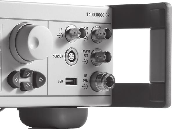
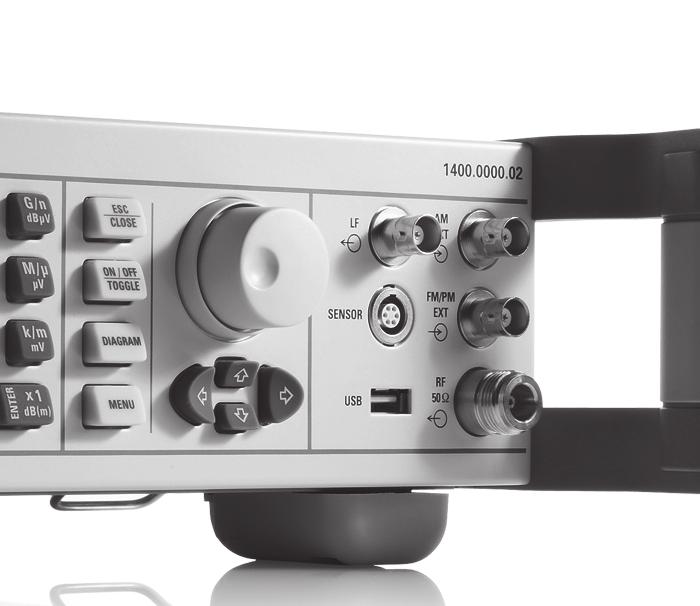
27 Version 06.01, June 2013 Connectors Front-panel connectors The following connectors are located on the front panel of the instrument as standard. Using the R&S SMA-B81 rear connector option the connectors can be moved to the rear panel of the instrument. RF 50Ω RF output N female LF modulation generator output BNC female AM EXT input for external amplitude modulation BNC female Input impedance > 100 kω Input sensitivity peak value for set modulation depth 1 V (nom.) Maximum input voltage 1 V (nom.) Input damage voltage ±6 V FM/PM EXT input for external frequency or phase modulation (only with R&S SMA-B20/-B22 option) BNC female Input impedance > 100 kω or 50 Ω (nom.) Input sensitivity peak value for set deviation 1 V (nom.) Maximum input voltage 1 V (nom.) Input damage voltage ±10 V SENSOR connector for R&S NRP-Zxx power sensor 6-pin ODU mini-snap series B USB USB 1.1 connector for external USB devices such as mouse, keyboard, R&S NRP-Zxx power sensors (with R&S NRP-Z4 adapter cable), memory stick for software update and data exchange, or USB serial adapter for RS-232-C remote control USB type A Rohde & Schwarz R&S SMA100A Signal Generator 27
R&S SMB100N SIGNAL GENERATOR
 R&S SMB100N SIGNAL GENERATOR PERFORMANCE SPECIFICATIONS VERSION 02.00, SEPTEMBER 2009 CONTENTS Specifications...3 Definitions... 3 RF performance... 4 Frequency... 4 Frequency sweep... 4 Reference frequency...
SMA100A Signal Generator
 Version 02.02 SMA100A Signal Generator August 2007 Data sheet CONTENTS KEY FEATURES...3 SPECIFICATIONS...4 RF CHARACTERISTICS...4 Frequency...4 Frequency sweep...4 Reference frequency...4 Level...5 Level
Signal Generator SMA100A
 Specifications Version 02.01 Signal Generator SMA100A November 2006 Specifications CONTENTS KEY FEATURES... 3 SPECIFICATIONS... 4 RF CHARACTERISTICS... 4 Frequency... 4 Frequency sweep... 4 Reference frequency...
Signal Generator SMA 100A
 Specifications Version 01.01 Signal Generator SMA 100A April 2006 Specifications CONTENTS CONTENTS... 2 KEY FEATURES... 3 SPECIFICATIONS... 4 RF CHARACTERISTICS... 4 Frequency... 4 Frequency sweep... 4
R&S SMA100B RF and Microwave Signal Generator Specifications
 R&S SMA100B RF and Microwave Signal Generator Specifications year Data Sheet Version 03.00 CONTENTS Key features... 4 Definitions... 5 Introduction... 6 Frequency and platform options (mandatory options)...
R&S SMW200A Vector Signal Generator Specifications
 R&S SMW200A Vector Signal Generator Specifications year Data Sheet Version 04.04 CONTENTS Key features... 4 Definitions... 5 Frequency and baseband main module options... 6 Frequency options... 6 Signal
Signal Generator SMA100A
 Product brochure Version 02.01 Signal Generator SMA100A November 2006 The new standard of excellence in the analog signal generator class Excellent signal quality Ideal for use in production All-purpose
R&S SMA100A Signal Generator The new standard of excellence in the analog signal generator class
 SMA100A_bro_en_5213-6412-12.indd 1 Product Brochure 06.01 Test & Measurement R&S SMA100A Signal Generator The new standard of excellence in the analog signal generator class 04.06.2013 10:13:49 R&S SMA100A
R&S SMC100A Signal Generator Specifications
 R&S SMC100A Signal Generator Specifications Test & Measurement Data Sheet 01.00 CONTENTS Key features... 3 Specifications... 4 RF characteristics...4 Frequency...4 Frequency sweep...4 Reference frequency...4
Analog signal generator that meets virtually every requirement
 GENERAL PURPOSE 44434/5 FIG 1 The R&S SMA1A offers excellent performance and compact design at a favorable price. Signal Generator R&S SMA1A Analog signal generator that meets virtually every requirement
Model 855 RF / Microwave Signal Generator
 Features Very low phase noise Fast switching Phase coherent switching option 2 to 8 phase coherent outputs USB, LAN, GPIB interfaces Applications Radar simulation Quantum computing High volume automated
Model 745 Series. Berkeley Nucleonics Test, Measurement and Nuclear Instrumentation since Model 845-HP Datasheet BNC
 Model 845-HP Datasheet Model 745 Series Portable 20+ GHz Microwave Signal Generator High Power +23dBM Power Output 250 fs Digital Delay Generator BNC Berkeley Nucleonics Test, Measurement and Nuclear Instrumentation
Model 865 RF / Ultra Low Noise Microwave Signal Generator
 Model 865 RF / Ultra Low Noise Microwave Signal Generator Features Excellent signal purity: ultra-low phase noise and low spurious Combination of highest output power and fastest switching Powerful touch-display
R&S SMW200A Vector Signal Generator Specifications
 SMW200A_dat-sw_en_3606-8037-22_v0302_cover.indd 1 Data Sheet 03.02 Test & Measurement R&S SMW200A Vector Signal Generator Specifications 19.03.2015 09:39:58 CONTENTS Key features... 4 Definitions... 5
R&S SMW200A Vector Signal Generator Specifications
 R&S SMW200A Vector Signal Generator Specifications year Data Sheet Version 07.00 CONTENTS Key features... 5 Definitions... 6 Frequency and baseband main module options... 7 Frequency options... 7 Signal
Chapter 6 Specifications
 RIGOL This chapter lists the technical specifications and general specifications of the RF signal generator. The technical specifications are valid when the instrument is within the calibration period,
R&S NRP-Zxx Power Sensors Specifications
 R&S NRP-Zxx Power Sensors Specifications year Data Sheet Version 11.00 CONTENTS Definitions... 3 Overview of the R&S NRP-Zxx power sensors... 4 Specifications in brief of the R&S NRP-Zxx power sensors...
Chapter 6 Specifications
 RIGOL This chapter describes the specifications of RF signal generator. Specifications are valid under the following conditions: the instrument in the calibration cycle is stored at least two hours at
Keysight Technologies E8257D PSG Microwave Analog Signal Generator. Data Sheet
 Keysight Technologies E8257D PSG Microwave Analog Signal Generator Data Sheet 02 Keysight E8257D Microwave Analog Signal Generator - Data Sheet Table of Contents Specifications... 4 Frequency... 4 Step
Model 865-M Wideband Synthesizer
 Model 865-M Wideband Synthesizer Features Wideband Low phase noise Fast switching down to 15 µs FM, Chirps, Pulse Internal OCXO, external variable reference Single DC supply Applications ATE LO for frequency
Model 745 Series. Berkeley Nucleonics Test, Measurement and Nuclear Instrumentation since Model 845-M Specification 1.8 BNC
 Specification 1.8 Model 745 Series 0.01-20.0 GHz Low Phase Noise Synthesizer 250 fs Digital Delay Generator Berkeley Nucleonics Test, Measurement and Nuclear Instrumentation since 1963 Introduction The
R&S SMA100A Signal Generator The new standard of excellence in the analog signal generator class
 SMA100A_bro_en_5213-6412-12.indd 1 Product Brochure 07.00 Test & Measurement R&S SMA100A Signal Generator The new standard of excellence in the analog signal generator class 25.10.2013 14:34:35 R&S SMA100A
Model 865-M Wideband Synthesizer
 Model 865-M Wideband Synthesizer Features Wideband Low phase noise Fast switching down to 20 µs FM, Chirps, Pulse Internal OCXO, external variable reference Single DC supply Applications ATE LO for frequency
Compact, easy to use, high performance signal generator for R&D, manufacturing and the field
 S-Series SGA Fast, Low Noise Signal Generator Compact, easy to use, high performance signal generator for R&D, manufacturing and the field Features Wide band cover: SGA-3-100 khz to 3 GHz SGA-6-100 khz
RF Signal Generator RIGOL TECHNOLOGIES, INC.
 DSG800 Series RF Signal Generator Highly cost-effective economical RF signal generator Up to -105 dbc/hz (typical) phase noise Up to +20 dbm (typical) maximum output power Higher level of amplitude accuracy,
R&S NRP Power Meter Family Specifications
 R&S NRP Power Meter Family Specifications year Data Sheet Version 06.00 CONTENTS Definitions... 3 Overview of the R&S NRP power sensors... 4 Specifications in brief of the R&S NRP power sensors... 5 Multipath
Keysight Technologies E8257D PSG Microwave Analog Signal Generator
 Ihr Spezialist für Mess- und Prüfgeräte Keysight Technologies E8257D PSG Microwave Analog Signal Generator Data Sheet datatec Ferdinand-Lassalle-Str. 52 72770 Reutlingen Tel. 07121 / 51 50 50 Fax 07121
R&S ZVT Vector Network Analyzer Specifications
 R&S ZVT Vector Network Analyzer Specifications Test & Measurement Data Sheet 08.00 CONTENTS Definitions... 3 Specifications... 4 Measurement range...4 Measurement speed...5 Measurement accuracy...6 Effective
APPH6040B / APPH20G-B Specification V2.0
 APPH6040B / APPH20G-B Specification V2.0 (July 2014, Serial XXX-XX33XXXXX-XXXX or higher) A fully integrated high-performance cross-correlation signal source analyzer for to 7 or 26 GHz 1 Introduction
GT 9000 GT 9000S MICROWAVE
 Page 1 of 6 GT 9000 GT 9000S MICROWAVE Now you can get the performance you need and the capability you want, at a price you can afford. Both the Giga-tronics GT9000 Microwave Synthe- techniques.together,
Agilent E4428C ESG Analog Signal Generator
 Migrate to the new Agilent MXG X-Series signal generator and generate true performance The new MXG exceeds the ESG s performance in every category - output power, phase noise, spurious, and low frequency
Berkeley Nucleonics Test, Measurement and Nuclear Instrumentation since 1963
 Model 845 Specification 2.54 (Sep 2017) Portable 12, 20, & 26.5 GHz Microwave Signal Generator with options HP, PE, R, LN, FS & LO BNC Berkeley Nucleonics Test, Measurement and Nuclear Instrumentation
Model 7000 Series Phase Noise Test System
 Established 1981 Advanced Test Equipment Rentals www.atecorp.com 800-404-ATEC (2832) Model 7000 Series Phase Noise Test System Fully Integrated System Cross-Correlation Signal Analysis to 26.5 GHz Additive
Model 845-M Low Noise Synthesizer
 Model 845-M Low Noise Synthesizer Features Low phase noise Fast switching down to 20 µs FM, Chirps, Pulse Internal OCXO, external variable reference Single DC supply Applications ATE LO for frequency converters
MG3740A Analog Signal Generator. 100 khz to 2.7 GHz 100 khz to 4.0 GHz 100 khz to 6.0 GHz
 Data Sheet MG3740A Analog Signal Generator 100 khz to 2.7 GHz 100 khz to 4.0 GHz 100 khz to 6.0 GHz Contents Definitions, Conditions of Specifications... 3 Frequency... 4 Output Level... 5 ATT Hold...
R&S FSWP Phase Noise Analyzer Specifications
 R&S FSWP Phase Noise Analyzer Specifications Data Sheet Version 06.00 CONTENTS Definitions... 4 Specifications... 5 Frequency... 5 Phase noise measurements... 5 Phase noise sensitivity with R&S FSWP-B61
RF Signal Generators. SG380 Series DC to 2 GHz, 4 GHz and 6 GHz analog signal generators. SG380 Series RF Signal Generators
 RF Signal Generators SG380 Series DC to 2 GHz, 4 GHz and 6 GHz analog signal generators SG380 Series RF Signal Generators DC to 2 GHz, 4 GHz or 6 GHz 1 µhz resolution AM, FM, ΦM, PM and sweeps OCXO timebase
Chapter 5 Specifications
 RIGOL Specifications are valid under the following conditions: the instrument is within the calibration period, is stored for at least two hours at 0 to 50 temperature and is warmed up for 40 minutes.
2400C Series Microwave Signal Generators 10 MHz to 40 GHz. Preliminary Technical Datasheet. Low Phase Noise and Fast-Switching Speed in a Single Unit
 Preliminary Technical Datasheet 2400C Series Microwave Signal Generators 10 MHz to 40 GHz Low Phase Noise and Fast-Switching Speed in a Single Unit 2400C Series Microwave Signal Generator Signal Generator
R&S ZVT Vector Network Analyzer Specifications
 ZVT_dat-sw_en_0758-065-22_v0900_cover.indd Data Sheet 09.00 Test & Measurement R&S ZVT Vector Network Analyzer Specifications 06.03.205 5:50:4 CONTENTS Definitions... 3 Specifications... 4 Measurement
R&S ZNC Vector Network Analyzer Specifications
 ZNC3_dat-sw_en_5214-5610-22_v0300_cover.indd 1 Data Sheet 03.00 Test & Measurement R&S ZNC Vector Network Analyzer Specifications 04.09.2012 13:39:47 CONTENTS Definitions... 3 Measurement range... 4 Measurement
10 V (Vpp) into 50 Ω load < 115 dbc (1 Hz) (typ.) 70 dbc (f < 1 MHz) AM, FM, pulse, PWM, 70 dbc + (f = 1 GHz)
 into 50 Ω load < 115 dbc (1 Hz) (typ.) 70 dbc (f < 1 MHz) AM, FM, pulse, PWM, 70 dbc + (f = 1 GHz)") /designation Frequency range Max. output power/voltage SSB phase noise Nonharmonics Modulation HMF arbitrary function generator 10 μhz to 25 MHz/50 MHz 10 V (Vpp) into 50 Ω load < 115 dbc (1 Hz) (typ.)
/designation Frequency range Max. output power/voltage SSB phase noise Nonharmonics Modulation HMF arbitrary function generator 10 μhz to 25 MHz/50 MHz 10 V (Vpp) into 50 Ω load < 115 dbc (1 Hz) (typ.)
RIGOL Data Sheet. DG3000 Series Function/Arbitrary Waveform Generator DG3121A, DG3101A, DG3061A. Product Overview. Easy to Use Design.
 RIGOL Data Sheet DG3000 Series Function/Arbitrary Waveform Generator DG3121A, DG3101A, DG3061A Product Overview DG3000 Series Function/Arbitrary Waveform Generators adopt DDS technology, which enables
R&S NRP USB and LAN Power Sensors Specifications
 R&S NRP USB and LAN Power Sensors Specifications year Test & Measurement Data Sheet 04.00 CONTENTS Definitions... 3 Overview of the R&S NRP power sensors... 4 Specifications in brief of the R&S NRP power
FREQUENCY SYNTHESIZERS, SIGNAL GENERATORS
 SYNTHESIZED SIGNAL GENERATOR MG3641A/MG3642A 12 khz to 1040/2080 MHz NEW New Anritsu synthesizer technology permits frequency to be set with a resolution of 0.01 Hz across the full frequency range. And
Agilent 8360B Series Synthesized Swept Signal Generators 8360L Series Synthesized Swept CW Generators Data Sheet
 Agilent 8360B Series Synthesized Swept Signal Generators 8360L Series Synthesized Swept CW Generators Data Sheet 10 MHz to 110 GHz Specifications apply after full user calibration, and in coupled attenuator
Agilent 83711B and 83712B Synthesized CW Generators
 View at www.testequipmentdepot.com Agilent 83711B and 83712B Synthesized CW Generators Agilent 83731B and 83732B Synthesized Signal Generators Data Sheet 10 MHz to 20 GHz 1 to 20 GHz Specifications describe
R&S ZNBT8 Vector Network Analyzer Specifications
 E stablished 1981 Advanced Test Equipment Rentals www.atecorp.com 800-404-ATEC (2832) ZNBT8_dat-sw_en_3606-9727-22_v0200_cover.indd 1 Data Sheet 02.00 Test & Measurement R&S ZNBT8 Vector Network Analyzer
DSA700 Series Spectrum Analyzer
 DSA700 Series Spectrum Analyzer Product Features: All-Digital IF Technology Frequency Range from 100 khz up to 1 GHz Min. -155 dbm Displayed Average Noise Level (Typ.) Min.
Signal Generator SML
 Signal Generator SML Economy at its best 9 khz to 1.1 GHz/2.2 GHz/3.3 GHz SSB phase noise: < 122 dbc (1 Hz) (at f = 1 GHz, f = 20 khz) Setting times
R&S ZNB Vector Network Analyzer Specifications
 Umschlag_ZNB4-8_dat-sw_en_5214-5384-22.indd 1 Data Sheet 02.00 Test & Measurement R&S ZNB Vector Network Analyzer Specifications 07.11.2011 10:03:35 CONTENTS Definitions... 3 Measurement range... 4 Measurement
Arbitrary/Function Waveform Generators 4075B Series
 Data Sheet Arbitrary/Function Waveform Generators Point-by-Point Signal Integrity The Arbitrary/Function Waveform Generators are versatile high-performance single- and dual-channel arbitrary waveform generators
2026Q CDMA/GSM Interferer MultiSource Generator
 Signal Sources 2026Q CDMA/GSM Interferer MultiSource Generator The 2026Q is designed to work with a radio test set to provide a fully integrated radio receiver test solution for cellular and PCS systems
RF Signal Generators. SG380 Series DC to 2 GHz, 4 GHz and 6 GHz analog signal generators. SG380 Series RF Signal Generators
 RF Signal Generators SG380 Series DC to 2 GHz, 4 GHz and 6 GHz analog signal generators SG380 Series RF Signal Generators DC to 2 GHz, 4 GHz or 6 GHz 1 μhz resolution AM, FM, ΦM, PM and sweeps OCXO timebase
This section lists the specications for the Agilent 8360 B-Series. generators, Agilent Technologies has made changes to this product
 2c Specifications This section lists the specications for the Agilent 8360 B-Series swept signal generator. In a eort to improve these swept signal generators, Agilent Technologies has made changes to
Signal Sources. 2026A/B 10 khz to 2.05/2.51 GHz MultiSource Generator.
 Signal Sources 2026A/B 10 khz to 2.05/2.51 GHz MultiSource Generator Up to three fully functional signal generators in one unit offering a unique solution for complex tests on receivers, components and
SIGNAL GENERATORS. MG3633A 10 khz to 2700 MHz SYNTHESIZED SIGNAL GENERATOR GPIB
 SYNTHESIZED SIGNAL GENERATOR MG3633A GPIB For Evaluating of Quasi-Microwaves and Measuring High-Performance Receivers The MG3633A has excellent resolution, switching speed, signal purity, and a high output
2026A/B 10 khz to 2.05/2.51 GHz MultiSource Generator
 Signal Sources 2026A/B 10 khz to 2.05/2.51 GHz MultiSource Generator Up to three fully functional signal generators in one unit offering a unique solution for complex tests on receivers, components and
 10 khz to 5.4 GHz Low Noise Signal Generator Signal Generators Excellent noise characteristics and low spurious signals for a wide range of critical measurements Wide band cover: 10 khz to 1.35 GHz (2040)
Racal Instruments. Product Information
 Racal Instruments 3172 200 MS/s Waveform Generator & Dual 50 MHz Pulse/ Timing Generator The, a 200 MS/s Waveform Generator and Dual 50 MHz Pulse and Timing Generator, combines multi-instrument density
R&S FSWP Phase Noise Analyzer Specifications
 R&S FSWP Phase Noise Analyzer Specifications Test & Measurement Data Sheet 05.00 CONTENTS Definitions... 4 Specifications... 5 Frequency... 5 Phase noise measurements... 5 Phase noise sensitivity with
Keysight Technologies EXG X-Series Signal Generator N5173B Microwave Analog
 Keysight Technologies EXG X-Series Signal Generator N5173B Microwave Analog 9 khz to 13, 20, 31.8, or 40 GHz Data Sheet Table of Contents Definitions.... 2 Frequency specifications.... 3 Amplitude specifications....
Advanced Test Equipment Rentals ATEC (2832)
") Established 1981 Advanced Test Equipment Rentals www.atecorp.com 800-404-ATEC (2832) Data sheet Version 06.00 Signal Generator SML August 2004 Economy at its best 9 khz to 1.1 GHz/2.2 GHz/3.3 GHz SSB phase
Established 1981 Advanced Test Equipment Rentals www.atecorp.com 800-404-ATEC (2832) Data sheet Version 06.00 Signal Generator SML August 2004 Economy at its best 9 khz to 1.1 GHz/2.2 GHz/3.3 GHz SSB phase
4 K to 512 K words (2 n, n = 12 to 19) or 2 to 10,000 control points (linear interpolation between control points)
 or 2 to 10,000 control points (linear interpolation between control points)") The values of items marked with *1 are guaranteed values. All other values are either nominal values or typical (typ.) values, and are not guaranteed. Conditions unless otherwise mentioned are as follows:
The values of items marked with *1 are guaranteed values. All other values are either nominal values or typical (typ.) values, and are not guaranteed. Conditions unless otherwise mentioned are as follows:
Agilent N5183A MXG Microwave Analog Signal Generator. Data Sheet
 Agilent N5183A MXG Microwave Analog Signal Generator Data Sheet Table of Contents Definitions...3 Frequency...4 Amplitude...5 Spectral Purity...8 Analog Modulation... 10 Frequency bands... 10 Frequency
WaveStation Function/Arbitrary Waveform Generators
 WaveStation Function/Arbitrary Waveform Generators Key Features High performance with 14-bit, 125 MS/s and 16 kpts 2 channels on all models Large 3.5 color display for easy waveform preview Over 40 built-in
Spectrum Analyzer R&S FS300
 Spectrum Analyzer R&S FS300 9 khz to 3 GHz The new product family from Rohde & Schwarz Professional test equipment for laboratory, service and production The R&S FS300 is a highly accurate spectrum analyzer
Spectrum Analyzer FSL
 Specifications Version 02.00 Spectrum Analyzer FSL August 2005 Specifications Specifications Specifications apply under the following conditions: 15 minutes warm-up time at ambient temperature, specified
Vector Network Analyzers ZVB
 Specifications Version 05.00 Vector Network Analyzers ZVB September 2005 Specifications MEASUREMENT RANGE...3 MEASUREMENT SPEED...5 MEASUREMENT ACCURACY...6 EFFECTIVE SYSTEM DATA...8 TEST PORT OUTPUT...8
Keysight Technologies MXG X-Series Signal Generator N5183B Microwave Analog
 Keysight Technologies MXG X-Series Signal Generator N5183B Microwave Analog 9 khz to 13, 20, 31.8, or 40 GHz Data Sheet 02 Keysight MXG X-Series Signal Generator N5183B Microwave Analog - Data Sheet Definitions
MODELS WW5061/2. 50MS/s Single/Dual Channel Arbitrary Waveform Generators
 Single / Dual Channel 50MS/s waveform generator Sine waves to 25MHz, Square to 15MHz SINE OUT to 50MHz, 1Vp-p 11 Built-in popular standard waveforms 14 Bit amplitude resolution 11 digits frequency resolution
DG4000 Series Waveform Generators
 No.1 DG4000 DG4000 series is a multifunctional generator that combines many functions in one, including Function Generator, Arbitrary Waveform Generator, Pulse Generator, Harmonic Generator, Analog/Digital
RIGOL Data Sheet. DG2000 Series Function/Arbitrary Waveform Generator DG2041A, DG2021A. Product Overview. Main Features.
 RIGOL Data Sheet DG2000 Series Function/Arbitrary Waveform Generator DG2041A, DG2021A Product Overview DG2000 Series Function/Arbitrary Waveform Generators adopt DDS technology, which enables to generate
Contents. ZT530PCI & PXI Specifications. Arbitrary Waveform Generator. 16-bit, 400 MS/s, 2 Ch
 ZT530PCI & PXI Specifications Arbitrary Waveform Generator 16-bit, 400 MS/s, 2 Ch Contents Outputs... 2 Digital-to-Analog Converter (DAC)... 3 Internal DAC Clock... 3 Spectral Purity... 3 External DAC
Agilent N5181A MXG Analog Signal Generator
 Agilent N5181A MXG Analog Signal Generator Data Sheet Performance optimized for manufacturing Fast switching speeds Simplified self-maintenance Table of Contents Table of Contents..................................2
WaveStation Function/Arbitrary Waveform Generators
 WaveStation Function/Arbitrary Waveform Generators Key Features High performance with 14-bit, 125 MS/s and 16 kpts 2 channels on all models Large 3.5 color display for easy waveform preview Over 40 built-in
2030, 2031, 2032 Signal Generators
 Signal Sources 2030, 2031, 2032 Signal Generators A high performance signal generator with programmable modulation sources and LF output, wide modulation bandwidths, sweep capability and excellent accuracy.
RF Signal Generator SM300
 RF Signal Generator SM300 9 khz to 3 GHz With compliments Helmut Singer Elektronik www.helmut-singer.de info@helmut-singer.de fon +49 241 155 315 fax +49 241 152 066 Feldchen 16-24 D-52070 Aachen Germany
15. Specifications WF1947/WF
 15. Specifications 15.1 Oscillation Mode...15-2 15.2 Waveform...15-2 15.3 Frequency, Phase...15-3 15.4 Output Characteristics...15-3 15.5 Signal Characteristics...15-5 15.6 Modulated Oscillation Mode...15-7
WaveStation Function/Arbitrary Waveform Generators
 Function/Arbitrary Waveform Generators Key Features High performance with 14-bit waveform generation, up to 500 MS/s sample rate and up to 512 kpts memory 2 channels on all models Large color display for
Signal Sources Series Low Noise Signal Generator
 Signal Sources 2040 Series Low Noise Signal Generator Excellent noise characteristics and low spurious signals for a wide range of critical measurements Wide band cover: 10 khz to 1.35 GHz (2040) 10 khz
Function/Arbitrary Waveform Generator
 Distributed By: Signal Test, Inc 1529 Santiago Ridge Way San Diego, CA 92154 Tel. 1-619-575-1577 USA www.signaltestinc.com Sales@SignalTestInc.com DG1000ZSeries Function/Arbitrary Waveform Generator SiFi
Signal Sources. 2026Q CDMA Interferer Multisource Generator. Advanced Test Equipment Rentals ATEC (2832)
") Signal Sources Established 1981 Advanced Test Equipment Rentals www.atecorp.com 800-404-ATEC (2832) 2026Q CDMA Interferer Multisource Generator The 2026Q is designed to work with a radio test set to provide
Signal Sources Established 1981 Advanced Test Equipment Rentals www.atecorp.com 800-404-ATEC (2832) 2026Q CDMA Interferer Multisource Generator The 2026Q is designed to work with a radio test set to provide
Vector Signal Generator SMV03
 Data sheet Version 03.00 Vector Signal Generator SMV03 September 2004 Vector modulation in the analog class Frequency range 9 khz to 3.3 GHz I/Q modulator (100 MHz RF bandwidth) with excellent vector accuracy
Dual Channel Function/Arbitrary Waveform Generators 4050B Series
 Data Sheet Dual Channel Function/Arbitrary Waveform Generators The Dual Channel Function/ Arbitrary Waveform Generators are capable of generating stable and precise sine, square, triangle, pulse, and arbitrary
R&S SMW200A Vector Signal Generator Specifications
 www.atecorp.com 800-404-ATEC (2832) R&S SMW200A Vector Signal Generator Specifications SMW200A_dat-sw_en_3606-8037-22_v0102_cover.indd 1 Data Sheet 01.02 E stablished 1981 Advanced Test Equipment Rentals
Agilent E8247C/57C PSG CW and Analog Signal Generators
 Agilent E8247C/57C PSG CW and Analog Signal Generators Data Sheet All specifications and characteristics apply over a 0 to 55 C range (unless otherwise stated) and apply after a 45 minute warm-up time.
Agilent 8657A/8657B Signal Generators
 Agilent / Signal Generators Profile Spectral performance for general-purpose test Overview The Agilent Technologies and signal generators are designed to test AM, FM, and pulsed receivers as well as components.
Agilent N5181A MXG and N5161A MXG ATE Analog Signal Generators
 Agilent N5181A MXG and N5161A MXG ATE Analog Signal Generators Data Sheet Optimized for performance and speed Fast switching speeds Simplified self-maintenance High output power Table of Contents Definitions.........................................................
Keysight N5191A UXG X-Series Agile Signal Generator, Modified Version
 Keysight N5191A UXG X-Series Agile Signal Generator, Modified Version 10 MHz to 20 or 40 GHz Data Sheet 02 Keysight N5191A UXG X-Series Agile Signal Generator, Modified Version - Data Sheet Table of Contents
Agilent E4428C ESG Analog Signal Generator
 Agilent E4428C ESG Analog Signal Generator Data Sheet All specifications apply over a 0 to 55 C range (unless otherwise stated) and apply after a 45 minute warm-up time. Supplemental characteristics, denoted
Spectrum Analyzers 2680 Series Features & benefits
 Data Sheet Features & benefits n Frequency range: 9 khz to 2.1 or 3.2 GHz n High Sensitivity -161 dbm/hz displayed average noise level (DANL) n Low phase noise of -98 dbc/hz @ 10 khz offset n Low level
R&S SMB100A RF and Microwave Signal Generator Versatile, compact, up to 40 GHz; 170 GHz with upconverter
 R&S SMB100A RF and Microwave Signal Generator Versatile, compact, up to 40 GHz; 170 GHz with upconverter SMB100A_bro_en_5213_8396_12_v0600_neu.indd 1 Product Brochure 06.00 Test & Measurement year 23.03.2016
 10 khz to 5.4 GHz Signal Generator Signal Generators A high performance signal generator with programmable modulation sources and LF output, wide modulation bandwidths, sweep capability and excellent accuracy
R&S SMBV100B Vector Signal Generator Specifications
 R&S SMBV100B Vector Signal Generator Specifications Data Sheet Version 02.00 year SMBV100B_dat-sw_en_3607-8201-22_v0200_cover.indd 1 10.07.2018 12:23:58 CONTENTS At a glance... 4 Definitions... 5 RF characteristics...
Agilent 8360B Series Synthesized Swept Signal Generators 8360L Series Synthesized Swept CW Generators
 Agilent 8360B Series Synthesized Swept Signal Generators 8360L Series Synthesized Swept CW Generators Data Sheet Discontinued Product Information For Support Reference Only Information herein, may refer
R&S EB500 Monitoring Receiver Specifications
 Radiomonitoring & Radiolocation Data Sheet 01.02 R&S EB500 Monitoring Receiver Specifications CONTENTS Definitions... 3 Specifications... 4 Frequency...4 Linearity...4 Interference rejection...4 Noise
Signal Generators SMY
 NEW up to 25 dbm RF sweep 9 khz to 1040/2080 MHz Signal Generators SMY Versatility and low cost can go hand in hand Frequency resolution 1 Hz Level range 140 to +19 dbm, overrange up to 25 dbm (option)
Dual Channel Function/Arbitrary Waveform Generators 4050 Series
 Data Sheet Dual Channel Function/Arbitrary Waveform Generators The Dual Channel Function/Arbitrary Waveform Generators are capable of generating stable and precise sine, square, triangle, pulse, and arbitrary
ArbStudio Arbitrary Waveform Generators. Powerful, Versatile Waveform Creation
 ArbStudio Arbitrary Waveform Generators Powerful, Versatile Waveform Creation UNMATCHED WAVEFORM UNMATCHED WAVEFORM GENERATION GENERATION Key Features 125 MHz bandwidth 1 GS/s maximum sample rate Long