*PMLN5592G* PMLN5592G
|
|
|
- Estella Ward
- 6 years ago
- Views:
Transcription

1
2
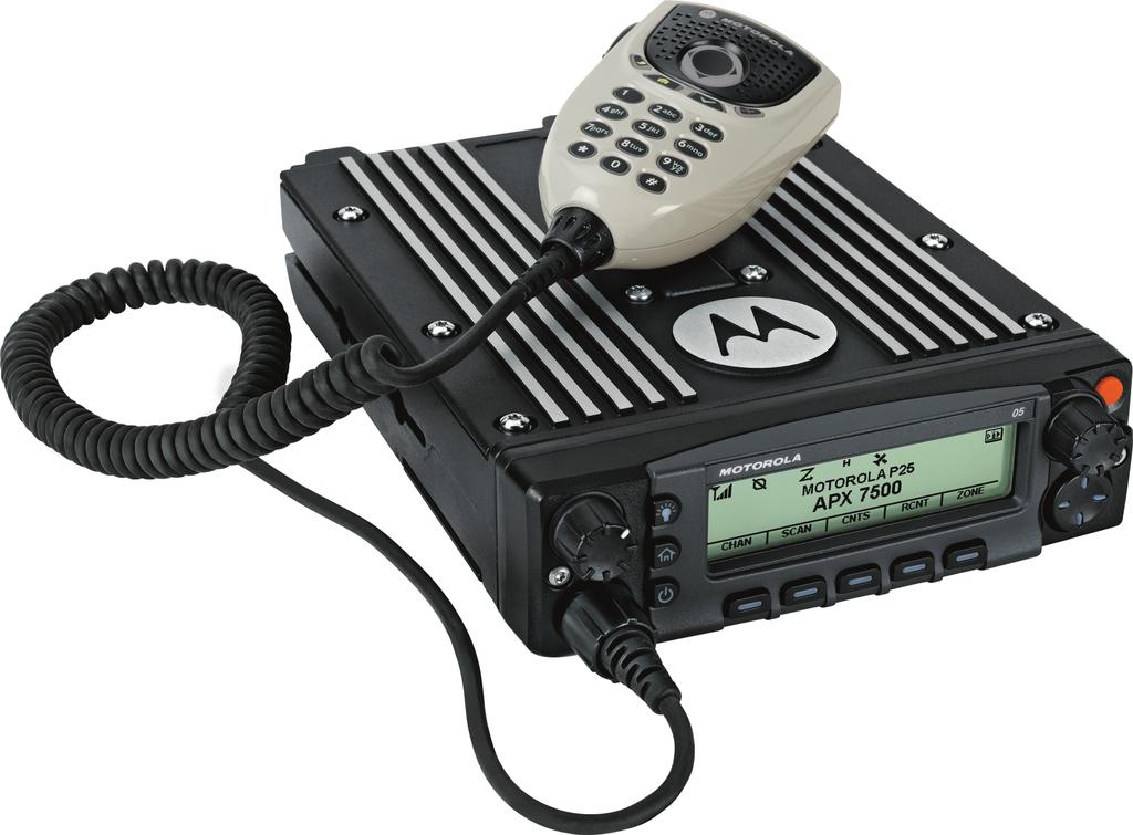
3 m ASTRO APX O5 Control Head Mobile Radio Quick Reference Card RF Energy Exposure and Product Safety Guide for Mobile Two-Way Radios ATTENTION! This radio is restricted to Occupational use only. Before using the radio, read the RF Energy Exposure and Product Safety Guide for Mobile Two-Way Radios which contains important operating instructions for safe usage and RF energy awareness and control for Compliance with applicable standards and Regulations. Radio Controls Volume Knob Dim Button Home Button Power On/Off Button Indicators Menu Entries Menu Select Button Accessory Port (Microphone) LED Indicators Mode Knob Orange Button Navigation Button Radio On/Off Press the Power On/Off button to toggle the power on or off.* * The duration that user must press and hold the Power On/Off button to turn off the radio is programmable by a qualified radio technician. Adjusting Volume Turn the Volume Knob clockwise to increase volume or counterclockwise to decrease the volume. Selecting a Zone 1 > or < to ZONE. 2 > or < button until the desired zone is displayed. 3 Press H or the PTT button to confirm the selected zone number. 4 Press the PTT button to begin transmitting on the displayed zone channel. Selecting a Channel 1 Press and hold > to scroll to CHAN and press the Menu Select button directly below CHAN. The display shows the current zone and channel. 2 Rotate the Mode knob to the desired channel. 3 Press H or the PTT button to confirm the channel. MOTOROLA, MOTO, MOTOROLA SOLUTIONS and the Stylized M logo are trademarks or registered trademarks of Motorola Trademark Holdings, LLC and are used under license. All other trademarks are the property of their respective owners , 2013, 2015 by Motorola Solutions, Inc. All Rights Reserved. 06/ East Algonquin Road, Schaumburg, Illinois 60196, U.S.A. 4 Press the PTT button to transmit on the displayed zone channel. Receiving and Transmitting 1 Take the microphone off hook. 2 Select zone/channel. 3 Listen for a transmission. OR Turn the Volume Knob. OR > or < to MON then press the Menu Select button directly below MON and listen for activity. 4 Adjust volume, if necessary. 5 Press the PTT button to transmit; release to receive. Sending an Emergency Alarm 1 Press the Emergency button. A tone sounds and the display alternates EMERGENCY and the home display. 2 A dispatcher acknowledgment ACK RECEIVED display follows. AND, Trunking Only: A high-pitched tone indicates that the alarm has been received by the trunked system s central controller. 3 Press and hold the emergency button or the PTT button to return to normal operation. To exit emergency at any time, press and hold the Emergency button. *PMLN5592G* PMLN5592G
4 Sending an Emergency Call (Trunking Only) 1 Press Emergency button. 2 A tone sounds and the display alternates EMERGENCY and the home display. OR A talk prohibited tone sounds when the selected channel does not support emergency. 3 Press and hold the PTT button. Speak clearly into the microphone. 4 Release the PTT to end the transmission. To exit emergency at any time, press and hold the Emergency button. Sending a Silent Emergency Alarm 1 Press the preprogrammed Emergency button to activate the silent alarm feature. 2 The display does not change; the LED does not light up, and there is no tone. O M K HOR. i j k Direct radio-to-radio communication or communication through a repeater. On = Direct Off = Repeater This channel is being monitored. Voice muting the affiliated trunking talkgroup or selected conventional channel. On = Enabled Off = Disabled L = Radio is set at Low power. H = Radio is set at High power. Scanning a scan list. Blinking dot = Detects activity on the Priority-One Channel during scan. Steady dot = Detects activity on the Priority- Two Channel during scan. The vote scan feature is enabled. m l G n o On = Secure operation. Off = Clear operation. Blinking = Receiving an encrypted voice call. On = AES Secure operation. Off = Clear operation. Blinking = Receiving an encrypted voice call. On = Location feature enabled, and location signal available. Off = Location feature disabled. Blinking = Location feature enabled, but location signal unavailable. On = User is currently associated with the radio. Off = User is currently not associated with the radio. Blinking = Device registration or user registration with the server failed due to an invalid username or pin. Data activity is present. If silent emergency alarm is used with emergency call, pressing the PTT button exits the silent mode and initiates the emergency call. { Indicates that the text entry is currently in hexadecimal mode. Display Status Icons u t V Receiving a call or data. Transmitting a call or data. The more stripes, the stronger the signal strength for the current site (trunking only). Menu Navigation < or > to Menu Entry. g directly below Menu Entry to select. < or > to scroll through sub-list. H to exit. g directly below Menu Entry to select.
5 Contents Declaration of Conformity... 8 Important Safety Information...10 Software Version...11 Notice to Users (FCC and Industry Canada)...11 Consignes de sécurité importantes...12 Version logicielle Avis aux utilisateurs (FCC et Industrie Canada)...13 Computer Software Copyrights...14 Documentation Copyrights...15 Disclaimer...16 Getting Started...17 How to Use This Guide...17 Notations Used in This Manual...17 Additional Performance Enhancement ASTRO 25 Enhanced Data...18 Dynamic System Resilience (DSR) CrossTalk Prevention...18 Encrypted Integrated Data (EID)...18 SecureNet...18 P25 Digital Vehicular Repeater System (DVRS) Conventional Talkgroup and Radio Scan Enhancements...19 What Your Dealer/System Administrator Can Tell You...19 Preparing Your Radio for Use...20 Contents 1
6 Contents 2 Turning On the Radio Adjusting the Volume...21 Validating Compatibility During Power Up Identifying Radio Controls...22 Radio Parts and Controls...22 Control Head and Microphone...22 Programmable Features...23 Assignable Radio Functions Assignable Settings or Utility Functions Accessing the Preprogrammed Functions...26 Menu Select Buttons...27 Advance Programmable Buttons Home Button Way Navigation Button Data Feature Button...28 Volume Knob Using the Mode Knob Keypad...29 Keypad Characters Uppercase Mode...29 Keypad Characters Lowercase Mode...30 Keypad Characters Numeric Mode...32 Keypad Characters Hexadecimal Mode...33 Push-To-Talk (PTT) Button...35 Identifying Status Indicators...36 Status Icons...36 Text Messaging Service (TMS) Indicators...38 TMS Status Icons...39 TMS Menu Options...40 LED Indicator...41 Intelligent Lighting Indicators Alert Tones General Radio Operation...47 Selecting a Zone...47 Selecting a Radio Channel Selecting a Channel via Channel Search Button Mode Select Feature Saving a Zone and a Channel to a Softkey...49
7 Saving a Zone and a Channel to a Button Receiving and Responding to a Radio Call Receiving and Responding to a Talkgroup Call...50 Receiving and Responding to a Private Call (Trunking Only)...51 Receiving and Responding to a Telephone Call (Trunking Only) Methods to Make a Radio Call...52 Making a Talkgroup Call Making a Private Call (Trunking Only) Making a Telephone Call (Trunking Only) Switching Between Repeater or Direct Operation Button Monitor Feature Monitoring a Channel...55 Monitoring Conventional Mode Advanced Features...57 Advanced Call Features Calling a Phone Not in the List...57 Selective Call (ASTRO Conventional Only) Talkgroup Call Feature (Conventional Operation Only) Sending a Status Call Responding to the Dynamic Regrouping Feature (Trunking Only) Dynamic Zone Programming (DZP)...61 Multiple Control Head Features...63 Setting the ID of the Initial Control Head All Active Mode Activating and Deactivating Intercom in All Active Mode One Active Mode Contacts...66 Making a Private Call from Contacts...67 Adding a New Contact Entry...68 Deleting a Contact Entry...68 Adding a Contact to a Call List...69 Methods of Contact Editing in a Call List Scan Lists Viewing a Scan List...71 Editing the Scan List Changing the Scan List Status...72 Contents 3
8 Contents 4 Viewing and Changing the Priority Status...73 Scan...73 Turning Scan On or Off...73 Turning Scan On While Disregarding the Squelch Code (Conventional Channels Only)...74 Transmitting While the Scan is On...74 Deleting a Nuisance Channel Restoring a Nuisance Channel Changing Priorities Status While Scan is On Restoring Priorities in a Scan List...75 Using the Hang Up Box (HUB) Call Alert Paging...76 Receiving a Call Alert Page Sending a Call Alert Page...77 Enabling and Disabling In-Call User Alert...78 Quick Call II (ASTRO P25 Digital Trunking and Conventional) Initiating a Quick Call II Transmission Emergency Operation...79 Sending an Emergency Alarm Sending an Emergency Call (Trunking Only) Sending an Emergency Alarm with Emergency Call Sending a Silent Emergency Alarm Special Considerations for Emergencies...82 Automatic Registration Service (ARS)...82 Selecting or Changing the ARS Mode...83 User Login Feature Text Messaging Service (TMS) Accessing the Messaging Features Composing and Sending a New Text Message Sending a Quick Text Message...88 Priority Status and Request Reply of a New Text Message Secure Operations...96 Enabling Secure Transmission Accessing the Secure Feature...97 Managing Encryption Global Positioning System / Global Navigation Satellite System GPS Operation GPS Performance Enhancement The Outdoor Location Feature (Using GPS)...103
9 Accessing the Outdoor Location Feature Turning Off GPS Saving a Waypoint Viewing a Saved Waypoint Editing the Alias of a Waypoint Editing the Coordinates of a Waypoint Deleting a Single Saved Waypoint Deleting All Saved Waypoints Measuring the Distance and Bearing from a Saved Waypoint Location Feature in Emergency Mode Peer-Location on the Display (ASTRO Conventional only) Geofence (ASTRO 25 Trunking System) Entering the Geofence Area Trunking System Controls Operating in Failsoft System Out-of-Range Radio SmartZone Site Trunking Feature Locking and Unlocking a Site Site Display and Search Button Trunked Announcement Ignition Switch Options Blank Tx Inhibit PTT Tx Inhibit Required Soft Power Off Ignition Only Power Up Using Emergency Power Up Auto Power Off Timer Voice Announcement Site Selectable Alerts (ASTRO 25) Sending SSA Notification to Single Site Sending SSA Notification to Single Site Via Manual Entry Sending SSA Notification to All Sites Sending SSA Notification to All Available Sites Stopping SSA Notification of a Single Site Stopping SSA Notification of a Single Site Via Manual Entry Stopping SSA Notification of All Sites Stopping SSA Notification of All Available Sites Contents 5
10 Contents 6 Channel Change on Off Hook on All Channels Low Voltage Threshold Warning Utilities Viewing Recent Calls Selecting the Power Level Selecting a Radio Profile Controlling the Display Backlight Turning the Keypad Tones On or Off Turning Voice Mute On or Off Using the Time-Out Timer Using Conventional Squelch Operation Features Using the PL Defeat Feature Digital PTT ID Support Smart PTT Feature (Conventional Only) Transmit Inhibit General Radio Information External Alarms (Horn and Lights) Helpful Tips Radio Care Cleaning the External Surface of the Radio Cleaning the External Plastic Surface Accessories Maritime Radio Use in the VHF Frequency Range Special Channel Assignments Emergency Channel Non-Commercial Call Channel Operating Frequency Requirements Declaration of Compliance for the Use of Distress and Safety Frequencies Technical Parameters for Interfacing External Data Sources Glossary Limited Warranty...154
11 MOTOROLA COMMUNICATION PRODUCTS I. WHAT THIS WARRANTY COVERS AND FOR HOW LONG: II. GENERAL PROVISIONS: III. STATE LAW RIGHTS: IV. HOW TO GET WARRANTY SERVICE:.156 V. WHAT THIS WARRANTY DOES NOT COVER: VI. PATENT AND SOFTWARE PROVISIONS: VII. GOVERNING LAW: VIII. For Australia Only SERVICE Contents 7
12 Declaration of Conformity This declaration is applicable to your radio only if your radio is labeled with the FCC logo shown below. Declaration of Conformity Per FCC CFR 47 Part 2 Section (a) Declaration of Conformity 8 Responsible Party Name: Motorola Solutions, Inc. Address: 1303 East Algonquin Road, Schaumburg, IL , U.S.A. Phone Number: Hereby declares that the product: Model Name: APX Mobile conforms to the following regulations: FCC Part 15, subpart B, section (a), (d) and section (a)
13 Class B Digital Device As a personal computer peripheral, this device complies with Part 15 of the FCC Rules. Operation is subject to the following two conditions: 1 This device may not cause harmful interference, and 2 This device must accept any interference received, including interference that may cause undesired operation. This equipment has been tested and found to comply with the limits for a Class B digital device, pursuant to part 15 of the FCC Rules. These limits are designed to provide reasonable protection against harmful interference in a residential installation. This equipment generates, uses and can radiate radio frequency energy and, if not installed and used in accordance with the instructions, may cause harmful interference to radio communications. However, there is no guarantee that interference will not occur in a particular installation. If this equipment does cause harmful interference to radio or television reception, which can be determined by turning the equipment off and on, the user is encouraged to try to correct the interference by one or more of the following measures: Reorient or relocate the receiving antenna. Increase the separation between the equipment and receiver. Connect the equipment into an outlet on a circuit different from that to which the receiver is connected. Consult the dealer or an experienced radio or TV technician for help. Declaration of Conformity 9
14 Important Safety Information 10 Important Safety Information RF Energy Exposure and Product Safety Guide for Mobile Two-Way Radios ATTENTION! This radio is restricted to Occupational use only. Before using the radio, read the RF Energy Exposure and Product Safety Guide for Mobile Two-Way Radios which contains important operating instructions for safe usage and RF energy awareness and control for Compliance with applicable standards and Regulations. For a list of Motorola-approved antennas and other accessories, visit the following website: Any modification to this device, not expressly authorized by Motorola, may void the user s authority to operate this device. Under Industry Canada regulations, this radio transmitter may only operate using an antenna of a type and maximum (or lesser) gain approved for the transmitter by Industry Canada. To reduce potential radio interference to other users, the antenna type and its gain should be so chosen that the equivalent isotropically radiated power (e.i.r.p.) is not more than that necessary for successful communication. This radio transmitter has been approved by Industry Canada to operate with Motorola-approved antenna with the maximum permissible gain and required antenna impedance for each antenna type indicated. Antenna types not included in this list, having a gain greater than the maximum gain indicated for that type, are strictly prohibited for use with this device. Setting up the radio as an RF Modem takes complete control of the radio. In this mode, the radio no longer responds to button and PTT presses nor will it unmute to voice activity. This mode is designed to receive and pass specifically formatted over the air data to a tethered computer with RF modem enabled applications. This mode can only be exit by reprogramming the radio with Customer Programming Software (CPS) to not operate in RF modem mode and cycling power.
15 Software Version All the features described in the following sections are supported by the software version R or later. See Accessing the Radio Information on page 135 to determine the software version of your radio. Check with your dealer or system administrator for more details of all the features supported. Software Version Notice to Users (FCC and Industry Canada) This device complies with Part 15 of the FCC rules and RSS 210 of the Industry Canada rules per the following conditions: This device may not cause harmful interference. This device must accept any interference received, including interference that may cause undesired operation. Changes or modifications made to this device, not expressly approved by Motorola, could void the authority of the user to operate this equipment. 11
16 Consignes de sécurité importantes 12 Consignes de sécurité importantes Radios bidirectionnelles mobiles : exposition aux radiofréquences et sécurité du produit ATTENTION! Cette radio ne doit être utilisée qu'à des fins professionnelles. Avant d'utiliser la radio, lisez le guide Radios bidirectionnelles mobiles : exposition aux radiofréquences et sécurité du produit, qui contient d'importantes instructions de fonctionnement pour une utilisation sécuritaire et des informations sur l'exposition aux fréquences radioélectriques, dans le but d assurer votre conformité aux normes et règlements en vigueur. Visitez le site Web suivant pour obtenir la liste des antennes et des autres accessoires approuvés par Motorola : Selon la réglementation d'industrie Canada, cet émetteur radio ne peut être utilisé qu'avec une antenne dont le type et le gain maximal (ou minimal) sont approuvés par Industrie Canada pour cet émetteur. Afin de limiter les interférences radio pour les autres utilisateurs, le type et le gain de l'antenne doivent être choisis de façon à ce que la puissance isotrope rayonnée équivalente (P.I.R.E.) ne soit pas plus forte qu'il ne le faut pour établir la communication. Cet émetteur radio a été approuvé par Industrie Canada pour utilisation avec une antenne approuvée par Motorola offrant le gain maximal autorisé et l'impédance requise pour le type d'antenne indiqué. Il est strictement interdit d'utiliser avec cet appareil tout type d'antenne ne figurant pas dans cette liste et présentant un gain supérieur au maximum indiqué pour le type.
17 Version logicielle Toutes les fonctions décrites dans les sections suivantes sont prises en charge par la version R ou les versions ultérieures du logiciel de la radio. Pour obtenir davantage de renseignements à propos des fonctions prises en charge, adressez-vous à votre détaillant ou à votre administrateur de système. Avis aux utilisateurs (FCC et Industrie Canada) Cet appareil est conforme à la Partie 15 des règlements de la FCC et RSS 210 du règlement d'industrie Canada selon les conditions énumérées ci-dessous: Ce dispositif ne doit pas causer d'interférences nuisibles. Cet appareil doit accepter toute interférence reçue, y compris les interférences qui peuvent perturber le fonctionnement. Les changements ou les modifications apportées à ce dispositif, non expressément approuvées par Motorola, peuvent annuler le droit de l'utilisateur à utiliser cet équipement. Version logicielle 13
18 Computer Software Copyrights Computer Software Copyrights The Motorola products described in this manual may include copyrighted Motorola computer programs stored in semiconductor memories or other media. Laws in the United States and other countries preserve for Motorola certain exclusive rights for copyrighted computer programs including, but not limited to, the exclusive right to copy or reproduce in any form the copyrighted computer program. Accordingly, any copyrighted Motorola computer programs contained in the Motorola products described in this manual may not be copied, reproduced, modified, reverse-engineered, or distributed in any manner without the express written permission of Motorola. Furthermore, the purchase of Motorola products shall not be deemed to grant either directly or by implication, estoppel, or otherwise, any license under the copyrights, patents or patent applications of Motorola, except for the normal nonexclusive license to use that arises by operation of law in the sale of a product. 14
19 Documentation Copyrights No duplication or distribution of this document or any portion thereof shall take place without the express written permission of Motorola. No part of this manual may be reproduced, distributed, or transmitted in any form or by any means, electronic or mechanical, for any purpose without the express written permission of Motorola. Documentation Copyrights 15
20 Disclaimer The information in this document is carefully examined, and is believed to be entirely reliable. However, no responsibility is assumed for inaccuracies. Furthermore, Motorola reserves the right to make changes to any products herein to improve readability, function, or design. Motorola does not assume any liability arising out of the applications or use of any product or circuit described herein; nor does it cover any license under its patent rights, nor the rights of others. Disclaimer 16
21 Getting Started How to Use This Guide This User Guide covers the basic operation of the APX Mobiles. However, your dealer or system administrator may have customized your radio for your specific needs. Check with your dealer or system administrator for more information. Notations Used in This Manual Throughout the text in this publication, you will notice the use of Warning, Caution, and Note. These notations are used to emphasize that safety hazards exist, and the care that must be taken or observed. Warning: An operational procedure, practice, or condition and so on, which may result in injury or death if not carefully observed. Caution: An operational procedure, practice, or condition and so on, which may result in damage to the equipment if not carefully observed. An operational procedure, practice, or condition and so on, which is essential to emphasize. The following special notations identify certain items. Example Home button or PHONE Description Buttons and keys are shown in bold print or as an icon. Menu entries are shown similar to the way they appear on the display of the radio. This means Press the right side of the 4-Way Navigation Button. Getting Started 17
22 Getting Started 18 Additional Performance Enhancement The following performance enhancements are some of the latest creations designed to enhance the security, quality and efficiency of the radios. ASTRO 25 Enhanced Data ASTRO 25 Enhanced Data is optimized to handle different message sizes and variable update rates from different applications of the radio. Add Enhanced Data to the Integrated Data system with a software installation to improve data channel efficiency and enable denser network traffic. Dynamic System Resilience (DSR) DSR ensures the radio system is seamlessly switched to a backup master site dynamically in case of system failure. DSR also provides additional indication e.g. failure detection, fault recovery, and redundancy within the system to address to the user in need. Mechanisms related to the Integrated Voice and Data (IV&D) or data centric are all supported by DSR. CrossTalk Prevention This feature prevents crosstalk scenarios from happening, especially when a wideband antenna is used. This feature allows the adjustment of the internal SSI clock rate of the radio. This subsequently reduces the possibility of radio frequency interfering spurs and prevents the issues of crosstalk. Encrypted Integrated Data (EID) EID provides security encryption and authentication of IV&D data bearer service communication between the radio and the Customer Enterprise Network. SecureNet SecureNet allows user to perform secured communications on an Analog or Motorola Data Communication (MDC) channel. The MDC Over-the- Air Rekeying (OTAR) feature will allow users to perform OTAR activities on an MDC channel. P25 Digital Vehicular Repeater System (DVRS) Motorola Solutions offers an MSI Certified APX compatible, 3rd Party, P25 Digital Vehicular Repeater System (DVRS) that provides low cost portable radio coverage in areas where only mobile radio coverage
23 is available and portable radio coverage is either intermittent or non-existent. Conventional Talkgroup and Radio Scan Enhancements A few enhancements have been made to the Conventional Talkgroup at the system. These enhancements improve the Scan feature operation significantly when multiple agencies are using a single conventional radio frequency channel. These enhancements allow users to use Selective Squelch to operate on only the subset of talkgroups that are relevant to the users rather than all talkgroups on the channel. These Scan improvements have been made to eliminate the audio holes that were present and to turn on the busy LED when activity is present on the channel. Mixed Vote Scan and Standard Conventional Scan configurations are supported. Priority Operation is also supported. Up to 30 different talkgroups can be supported using conventional channels. A maximum of four talkgroups can be supported when Vote Scan channels are being used. Smart PTT is supported with this enhancement as Smart PTT prevents users from transmitting while other users are on the channel. User Selectable Talkgroups are not compatible with this Conventional Talkgroup Enhancement. What Your Dealer/System Administrator Can Tell You Check with your dealer or system administrator, if the radio is to be operated in extremely cold temperatures (less than -30 C or more than +60 C), for the correct radio settings to ensure proper operation. You can consult your dealer or system administrator about the following: Is your radio programmed with any preset conventional channels? Which buttons have been programmed to access other features? What optional accessories may suit your needs? Specifications may vary for different radio models. Check with your dealer or system administrator for more information. Getting Started 19
24 Preparing Your Radio for Use 20 Preparing Your Radio for Use This section provides simple instructions to prepare your radio for use. Turning On the Radio 1 Press the Power On/Off Button briefly to power on the radio. A After a short time, the red, yellow and green LEDs light up. The display then shows Zone and channel text, and menu items display on the screen. The backlight turns on to the last selected dim level. Pressing the Power On/Off Button before the LED lights up will be ignored. If FAIL ##/## appears in the display, the radio will not function until the condition has been corrected. If ERROR ##/## appears, some non-critical data has been changed. If either of these displays appear, if the display goes blank, or if the unit appears to be locked up, see Helpful Tips on page 141 for more information. If CH MISMATCH appears, means that either the Control Head has been connected to an incompatible transceiver, or vice versa. If your radio does not power up, contact your dealer. 2 To turn off the radio, press the Power On/Off Button after the LEDs light up. The duration that user must press and hold the Power On/Off Button to turn off the
25 Adjusting the Volume radio is programmable by a qualified radio technician. 1 To increase the volume, rotate the Volume Knob clockwise. A 2 To decrease the volume, rotate this knob counterclockwise. Press the Power On/Off Button to reset when the display shows UPDATE DONE PLEASE RESET upon completion, or when the display shows UPDATE FAILED PLEASE RESET when it fails to update. If the software updates are complete, the radio runs the usual power up operation. If the updates are incomplete, the radio runs the Maintenance Mode and the display shows MAINTENANCE MODE REMOTE DEVICE; promptly followed by other maintenance statuses again. If SW INCOMPLETE appears, use Flashport Recovery Tool to update the control heads before you power on the radio again. Preparing Your Radio for Use Validating Compatibility During Power Up The radio validates and updates the software and hardware of your control head(s) during power up. During validation, the display shows MAINTENANCE MODE REMOTE DEVICE; promptly followed by other maintenance statuses. 21
26 Identifying Radio Controls Radio Parts and Controls Control Head and Microphone Identifying Radio Controls The microphone is not part of a radio. It is an optional accessory. 1 Accessory Port (Microphone) 2 Menu Select Button [1] 3 Menu Entries 4 LED Indicators 5 Navigation Button 6 Accy 2-Dot Button [1] 22 7 Accy 1-Dot Button [1]
27 8 Accy No-Dot Button (Purple) [1] 9 Push-to-Talk (PTT) Button 10 Orange Button [1] 11 Mode Knob 12 Indicators 13 Power On/Off Button 14 Home Button 15 Dim Button 16 Volume Knob 17 Data Feature Button [1] 18 Home Button (Microphone) 19 Keypad Buttons 20 Okay/Select Button ( ) 21 Cancel Button (X) 22 Navigation Button (Microphone) Programmable Features Any reference in this manual to controls that are preprogrammed means that a qualified radio technician must use the radio programming software to assign a feature to a control. Your dealer can program the programmable buttons as shortcuts to radio functions or preset channels/ groups depending on the duration of a button press: Press Pressing and releasing rapidly. Long press Pressing and holding for the preprogrammed duration (between 0.25 seconds and 3.75 seconds). Hold down Assignable Radio Functions Call Alert Keeping the button pressed. Allows the radio to function like a pager, or to verify if a radio is active on the system. Identifying Radio Controls 1 These radio controls/buttons are programmable. 23
28 Identifying Radio Controls Call Response Channel Contacts Dynamic ID (Conventional Only) Dynamic Priority (Conventional Only) Emergency Information Intercom Allows you to answer a private call or phone call. Selects a channel. Selects the Contacts menu. Allows you to edit the ASTRO Individual ID and/or MDC Primary ID of the radio. Allows any channel in a Scan List (except for the Priority-One channel) to temporarily replace the Priority-Two channel. Depending on the programming, initiates or cancels an emergency alarm or call. Displays the information of the radio. Enables users of multiple control heads to talk to each other via the control heads in a multi-control head setup. Internet Protocol Address Location Message Monitor (Conventional Only) Multiple Private Line (Conventional Only) Nuisance Delete Display the Internet Protocol (IP) address, device name and status of the radio. Determines the current location (latitude, longitude, time and date), and also the distance and bearing to another location. Or, turns the GPS functionality on or off for all locations. Enters the current message list. Monitors a selected channel for all radio traffic until function is disabled. Selects the Multiple Private Line lists. Temporarily removes an unwanted channel, except for priority channels or the designated transmit channel from the scan list. 24
29 Phone Private Call (Trunking Only) Radio Profiles Recent Calls Rekey Request Repeater Access Button (RAB) (Conventional Only) Launches a specific feature with one single button-press. You can setup as many as four separately programmed buttons for four different features. Allows you to make and receive calls similar to standard phone calls. Allows a call from an individual radio to another individual radio. Allows easy access to a set of preprogrammed visual and audio settings of the radio. Allows easy access to the list of calls recently received or made. Notifies the dispatcher you want a new encryption key. Allows user to manually send a repeater access codeword. Reprogram Request (Trunking Only) Request-To-Talk (Conventional Only) Scan Scan List Programming Secure/Clear Selective Call (Conventional Only) Siren Site Display/ Search (Trunking Only) Notifies the dispatcher you want a new dynamic regrouping assignment. Notifies the dispatcher you want to send a voice call. Toggles scan on or off. Selects the scan list for editing (by long press on the Scan button). Toggles secure transmission on or off. Calls an assigned radio. Turns different Siren Tones on or off. Displays the current site ID and RSSI value; performs site search for Automatic Multiple Site Select (AMSS) or SmartZone operation. Identifying Radio Controls 25
30 Identifying Radio Controls 26 Site Lock/Unlock (Trunking Only) Status (Astro 25 Trunking Only) Talkaround/Direct (Conventional Only) Talkgroup (Conventional Only) Text Messaging Service (TMS) TMS Quick Text User Zone Down Zone Select Zone Up Locks onto a specific site. Sends data calls to the dispatcher about a predefined status. Toggles between using a repeater and communicating directly with another radio. Allows a call from an individual radio to a group of radios. Selects the text messaging menu. Selects a predefined message. Automatically registers with the server. Toggles downward through the zones in the radio. Allows selection from a list of zones. Toggles upward through the zones in the radio. Assignable Settings or Utility Functions Dim Front/Rear Horns/Lights Keypad Lock Low Power Voice Announcement Voice Mute Changes the display brightness. Switches one of two control heads to be active at one time. Toggles horns and lights feature on or off. Toggles the keypad lock on or off. Toggles transmit power level between high and low. Audibly indicates the current feature mode, Zone or Channel the user has just assigned. Toggles voice mute on or off. Accessing the Preprogrammed Functions You can access various radio functions through one of the following methods.
31 A short or long press of the relevant programmable buttons. Use the Menu Select Button ( ). Menu Select Buttons Check with your dealer or system administrator for the list of features activated in your radio. Use the Menu Select button to access the menu entry of your radio feature. Your radio may be preprogrammed differently from the following example, but the steps for selecting a channel may appear as shown below: Press the Menu Select button ( CHAN. ) directly below Advance Programmable Buttons This feature is to help you to shorten the process of applying certain common features. B C D E A Identifying Radio Controls A A Orange Button [2] B Menu Select Buttons [2] 27
32 Identifying Radio Controls C Accy No-Dot Button (Purple) [2] D Accy 1-Dot Button [2] E Accy 2-Dot Button [2] (Quick Access) One Touch Button Home Button Enters a menu with a short press on the preprogrammed One Touch button. Features assigned to these buttons are Call, Call Alert, Phone, Repeater Access, MDC RTT Button Access, Status and Message. Pressing the button returns you to the Home (default) screen. In most cases, this is the current mode. For selected radio features, the button is also used to save user-edited radio settings or information before returning you to the Home screen. Some features do not require you to press to go to the Home screen. Refer to the individual feature sections in this manual for further details on saving user-edited radio settings or information. The button also can revert to home channel from any other zone and mode in the radio. Check with your dealer or system administrator for more information. 4-Way Navigation Button Use the 4-Way Navigation Button to scroll up, down, left or right with one of the following methods. Press and release one of the button to scroll from one entry to the next one. Press and hold one of the button to have the radio toggles through the list automatically (release the button to stop). Data Feature Button Use Data Feature button to access data-related features, such as the Text Messaging Service (TMS) feature screen These programmable buttons support the One Touch Button feature.
33 Volume Knob Use this Volume Knob to adjust the volume of the speakers by turning it clockwise or counterclockwise. Using the Mode Knob Keypad Use this Mode Knob to scroll through the channels by turning it clockwise or counterclockwise. You can use the 3 x 4 alphanumeric keypad on the keypad microphone to access your radio s features. Keypad Characters Uppercase Mode The keypad functions in a manner similar to a standard telephone keypad when entering numeric digits. When the keypad is used to edit a list, each key can generate different characters of the alphabet. The following tables show the number of times a key needs to be pressed to generate the required character. Identifying Radio Controls Key Number of Times Key is Pressed ,?! _ - * # & $ / + = \ ( ) A B C D E F G H I 29
34 Key Number of Times Key is Pressed J K L M N O P Q R S T U V W X Y Z Identifying Radio Controls 30 Toggle between mixed case mode, uppercase mode and lowercase mode. Space Toggle between numeric and letter mode. Keypad Characters Lowercase Mode Key Number of Times Key is Pressed ,?! _ - * # & $ / + = \ ( )
35 Key Number of Times Key is Pressed a b c d e f g h i j k l m n o p q r s t u v w x y z Toggle between mixed case mode, uppercase mode and lowercase mode. Space Toggle between numeric and letter mode. Identifying Radio Controls 31
36 Keypad Characters Numeric Mode Key Number of Times Key is Pressed ,?! _ - * # & $ / + = \ ( ) Identifying Radio Controls Space
37 Key Number of Times Key is Pressed Toggle between numeric and letter mode. Keypad Characters Hexadecimal Mode Key Number of Times Key is Pressed Identifying Radio Controls 2 A B C 3 D E F
38 Key Number of Times Key is Pressed Not applicable Not applicable Identifying Radio Controls 34
39 Push-To-Talk (PTT) Button A While a call is not in progress, the PTT button is used to make a new call. See Methods to Make a Radio Call on page 52 for more information. Identifying Radio Controls The PTT button on the side of the microphone serves two basic purposes: While a call is in progress, the PTT button allows the radio to transmit to other radios in the call. Press and hold down PTT button to talk. Release the PTT button to listen. The microphone is activated when the PTT button is pressed. 35
40 Identifying Status Indicators Status Icons The liquid crystal display (LCD) of your radio shows the radio status, text entries, and menu entries. The following are the icons that appear on the display of the radio. Receiving On Radio is currently configured for direct radio-to-radio communication (during conventional operation only). Off Radio is connected with other radios through a repeater. Monitor (Carrier Squelch) Selected channel is being monitored (during conventional operation only). Radio is receiving a call or data. In-Call User Alert Identifying Status Indicators 36 Transmitting Radio is transmitting a call or data. Received Signal Strength Indicator (RSSI) The number of bars displayed represents the received signal strength for the current site, for trunking only. The more stripes in the icon, the stronger the signal. Direct or On The feature is enabled. Voice muting of the affiliated trunking talkgroup or selected conventional channel is activated. Off The feature is disabled. Voice muting of the affiliated trunking talkgroup or selected conventional channel is deactivated. Power Level L Radio is set at Low power.
41 H Radio is set at High power. Scan Radio is scanning a scan list. Priority Channel Scan Blinking dot Radio detects activity on channel designated as Priority-One. Steady dot Radio detects activity on channel designated as Priority-Two. Vote Scan Enabled The vote scan feature is enabled. Secure Operation On Secure operation. Off Clear operation. Blinking Receiving an encrypted voice call. AES Secure Operation On AES secure operation. Off Clear operation. Blinking Receiving an encrypted voice call. GPS Signal On Feature is enabled and signal is available. Off Feature is disabled. Blinking Feature is enabled, but no signal is available. User Login Indicator (IP Packet Data) On User is currently associated with the radio. Off User is currently not associated with the radio. Blinking Device registration or user registration with the server failed due to an invalid username or pin. Inverted User successfully login to the secured IP Packet Data. Identifying Status Indicators 37
42 Identifying Status Indicators 38 Data Activity Data activity is present. Hexadecimal Indicates that the text entry is currently in hexadecimal mode. Numeric Indicates that the text entry is currently in numeric mode. Start Case Indicates that the first character of the text entry is capitalized. Mixed Case Indicates that the text entry is currently in normal text mode. Uppercase Indicates that the text entry is currently in uppercase mode. Lowercase Indicates that the text entry is currently in lowercase mode. Lowercase Predictive Indicates that the text entry is currently in lowercase and with predicted words shown at the bottom of the screen. Mixedcase Predictive Indicates that the text entry is currently in mixed case and with predicted words shown at the bottom of the screen. Uppercase Predictive Indicates that the text entry is currently in uppercase and with predicted words shown at the bottom of the screen. Text Messaging Service (TMS) Indicators This feature allows you to send and receive text messages. Status icons and menu options shown
43 here help you to work more efficiently with TMS feature. See Text Messaging Service (TMS) on page 86 for more information. TMS Status Icons The following icons appear on the radio s display when you send and receive text messages. Inbox Full The Inbox is full. Message Sent The text message is sent successfully. Message Unsent The text message cannot be sent. Unread Message User receives a new message. The selected text message in the Inbox has not been read. Read Message The selected text message in the Inbox has been read. Normal Message User is composing a message with normal priority and without a request for a reply. Message Index Indicates the index of the current message the user is viewing. Example: If the user is looking at the third message out of a total of 6 messages in the Inbox folder, the icon is displayed as the icon on the left column. Priority Status The Priority feature is toggled on before the message is sent. Messages in the Inbox folder are flagged with Priority. Request Reply Identifying Status Indicators 39
44 The Request Reply feature is toggled on before the message is sent. Messages in the Inbox folder are flagged with Request Reply. Menu Option SAVE Description/Function Saves the messages you have edited to the Draft folder. Priority Status and Request Reply SENT Brings you to the sent messages screen. Identifying Status Indicators 40 TMS Menu Options Menu Option INBX COMP DRFT BACK User is composing a message with a priority status and a request for a reply. Messages in the Inbox folder are flagged with Priority and Request Reply. Description/Function Brings you to your incoming messages screen. Brings you to the compose screen. Brings you to the saved message screen. Brings you back to the previous screen. NEW LIST IMPT RQRP CURR ALL DEL EDIT EXIT Creates a new message. Brings you to the predefined messages screen. Toggles the Priority Status icon on or off for an outgoing message. Toggles Request Reply icon on or off for an outgoing message. Deletes the current selected message. Selects to delete all the messages in the current folder. Deletes a message or text. Edits a draft message or key in a target address. Exits to the Home screen.
45 Menu Option NO OPTN RPLY SEL SEND YES Description/Function Cancel the delete all messages options. Brings you to the Options main screen. Replies to a message. Selects a predefined message or address. Sends the message. Deletes all the messages in the current folder. A B C Red LED Yellow LED Green LED Solid red Rapidly blinking red Solid yellow (Conventional Only) Radio is transmitting. Radio has failed the self test upon powering up or encountered a fatal error. Channel is busy. Identifying Status Indicators LED Indicator The LED indicator shows the operational status of your radio. A B C Blinking yellow Solid green Blinking green Radio is receiving a secured transmission. Radio is powering up, or is on a non-priority channel while in the Scan List Programming mode. Radio is receiving an individual or telephone call, or is on a Priority-Two channel while in the Scan List Programming mode. 41
46 Rapidly blinking green Intelligent Lighting Indicators Radio is on a Priority-One channel while in the Scan List Programming mode. This feature temporarily changes the display backlight color and the alert text background color of the radio to help signal that a radio event has occurred. This feature must be preprogrammed by a qualified radio technician. Identifying Status Indicators 42 Backlight and Bar Color Notification When Orange Emergency Alerts The radio initiates an emergency alarm or call. The radio receives an emergency alarm or call. Red Critical Alerts The radio battery is low. The radio is out of range. The radio enters Failsoft mode. The radio is unable to establish a full connection with the system. The radio is unable to authenticate or register with the system. The radio lost GPS signal or GPS function fails.
47 Backlight and Bar Color Notification When Green Call Alerts The radio receives a private call. Alert Tones The radio receives a phone call. The radio receives a call alert. The radio receives a selective call. The radio enters Geofence. Your radio uses alert tones to inform you of the condition of your radio. The following table lists these tones and when they occur. Identifying Status Indicators You Hear Tone Name Heard Short, Low- Pitched Tone Radio Self Test Fail Reject Time-Out Timer Warning No ACK Received Individual Call Warning Tone When radio fails its power-up self test. When an unauthorized request is made. Four seconds before time out. When radio fails to receive an acknowledgment. When radio is in an individual call for greater than 6 seconds without any activity. 43
48 You Hear Tone Name Heard Long, Low- Pitched Tone Time-Out Timer Timed Out Talk Prohibit/PTT Inhibit After time out. (When PTT button is pressed) transmissions are not allowed. Lack of Voice PTT Time out When the radio ends your call after it detected there are lack of voice for 5 seconds after the PTT is pressed and hold. Your radio ends the call to enable your radio to receive calls from other radio users. Out of Range (When PTT button is pressed) the radio is out of range of the system. Invalid Mode When radio is on an unpreprogrammed channel. Identifying Status Indicators 44 A Group of Low-Pitched Tones Short, Medium- Pitched Tone Busy Valid Key-Press Radio Self Test Pass Clear Voice Priority Channel Received Emergency Alarm /Call Entry When system is busy. When a correct key is pressed. When radio passes its power-up self test. At beginning of a non-coded communication. When activity on a priority channel is received. When entering the emergency state.
49 You Hear Tone Name Heard Long, Medium- Pitched Tone A Group of Medium-Pitched Tones Short, High- Pitched Tone (Chirp) Two High- Pitched Tones Central Echo Volume Set Emergency Exit Failsoft Automatic Call Back Keyfail Console Acknowledge Received Individual Call Call Alert Sent Site Trunking Low-Battery Chirp GPS Fails When central controller has received a request from a radio. When volume is changed on a quiet channel. When exiting the emergency state. When the trunking system fails. When voice channel is available from previous request. When encryption key has been lost. When status, emergency alarm, or reprogram request ACK is received. When Call Alert or Private Call is received. When Call Alert is received by the target radio. When a SmartZone trunking system fails. When battery is below preset threshold value. When the GPS signal is lost or when GPS fails. Ringing Fast Ringing When system is searching for target of Private Call. Identifying Status Indicators 45
50 You Hear Tone Name Heard Identifying Status Indicators Enhanced Call Sent Phone Call Received When waiting for target of Private Call to answer the call. When a land-to-mobile phone call is received. Gurgle Dynamic Regrouping (When PTT button is pressed) a dynamic ID has been received. Unique, Low- Pitched Chirp Unique, High- Pitched Chirp Talk Permit New Message Priority Status (When PTT button is pressed) is verifying with the system for accepting its transmissions. When a new message is received. When a priority message is received. 46
51 General Radio Operation Selecting a Zone Your radio must be preprogrammed to allow you to use this feature. A zone is a group of channels. The following methods are options on how to select a radio zone. The result of all the methods is the same. You can use the options interchangeably depending on your preference and the programmed functions. Select a zone via the Mode Knob: a) Rotate the Mode Knob until the display shows the desired zone. Select a zone via the radio menu ZONE: a) or to ZONE and press the Menu Select button directly below ZONE. b) or to the required zone, or use the keypad to enter the zone number. c) Press or the PTT button to confirm the selected zone number. d) Press the PTT button to transmit on the displayed zone channel. Selecting a Radio Channel A channel is a group of radio characteristics, such as transmit/ receive frequency pairs. The following methods are options on how to select a radio channel. The result of all the methods is the same. You can use the options interchangeably depending on your preference and the programmed functions. Select a channel via the Mode knob: a) Rotate the Mode knob until the display shows the desired channel. b) Press the PTT button to begin transmitting on the displayed channel. Select a channel via the radio menu CHAN: a) or to CHAN. b) Press the Menu Select button directly below CHAN. c) or to the required channel. d) Press the Menu Select button directly below SEL to confirm the selected channel. General Radio Operation 47
APX TWO-WAY RADIOS APX MOBILE O9 CONTROL HEAD USER GUIDE
 APX TWO-WAY RADIOS APX MOBILE O9 CONTROL HEAD USER GUIDE m 1 2 3 4 ASTRO APX O9 Control Head Mobile Radio Quick Reference Card RF Energy Exposure and Product Safety Guide for Mobile Two-Way Radios ATTENTION!
APXTM TWO-WAY RADIOS APX MOBILE O3 CONTROL HEAD USER GUIDE
 APXTM TWO-WAY RADIOS APX MOBILE O3 CONTROL HEAD USER GUIDE Programmable Button (Purple) m ASTRO APX O3 Control Head Mobile Radio Quick Reference Card RF Energy Exposure and Product Safety Guide for Mobile
APXTM TWO-WAY RADIOS APX MOBILE O2 CONTROL HEAD USER GUIDE
 APXTM TWO-WAY RADIOS APX MOBILE O2 CONTROL HEAD USER GUIDE m ASTRO APX O2 Control Head Mobile Radio Quick Reference Card RF Energy Exposure and Product Safety Guide for Mobile Two-Way Radios ATTENTION!
 Contents Declaration of Conformity... 8 Computer Software Copyrights...14 Documentation Copyrights...15 Contents Important Safety Information...10 Disclaimer...16 Notice to Users (FCC and Industry Canada)...11
APXTM TWO-WAY RADIOS APX MOBILE O2 CONTROL HEAD USER GUIDE
 APXTM TWO-WAY RADIOS APX MOBILE O2 CONTROL HEAD USER GUIDE m ASTRO APX O2 Control Head Mobile Radio Quick Reference Card RF Energy Exposure and Product Safety Guide for Mobile Two-Way Radios ATTENTION!
APX TWO-WAY RADIOS APX 1000 MODEL 3 USER GUIDE APX 1000
 APX TWO-WAY RADIOS APX 1000 MODEL 3 USER GUIDE APX 1000 m ASTRO APX 1000 Series Digital Portable Radios Quick Reference Card RF Energy Exposure and Product Safety Guide for Portable Two-Way Radios ATTENTION!
*PMLN7345A* PMLN7345A
 m ASTRO APX 4000XH Series Digital Portable Radios Quick Reference Card RF Energy Exposure and Product Safety Guide for Portable Two-Way Radios ATTENTION! This radio is restricted to Occupational use only.
APX TWO-WAY RADIOS APX 1000 MODEL 2 USER GUIDE
 APX TWO-WAY RADIOS APX 1000 MODEL 2 USER GUIDE m ASTRO APX 1000 Model 2 Digital Portable Radios Quick Reference Card RF Energy Exposure and Product Safety Guide for Portable Two-Way Radios ATTENTION!
SRX TWO-WAY RADIOS SRX 2200 MODEL 3.5 USER GUIDE
 SRX TWO-WAY RADIOS SRX 2200 MODEL 3.5 USER GUIDE m ASTRO SRX 2200 Series Digital Portable Radios Quick Reference Card RF Energy Exposure and Product Safety Guide for Portable Two-Way Radios ATTENTION!
BERKS COUNTY. APX TM 6500 O5 Control Head. Select image from Photo Library Insert and resize image to fill up this white area Send (image) to back
 to back") APX Two-Way Radios BERKS COUNTY Select image from Photo Library Insert and resize image to fill up this white area Send (image) to back APX TM 6500 O5 Control Head DECLARATION OF CONFORMITY This declaration
APX Two-Way Radios BERKS COUNTY Select image from Photo Library Insert and resize image to fill up this white area Send (image) to back APX TM 6500 O5 Control Head DECLARATION OF CONFORMITY This declaration
APX TWO-WAY RADIOS APX 6000XE MODEL 3 USER GUIDE
 APX TWO-WAY RADIOS APX 6000XE MODEL 3 USER GUIDE m ASTRO APX 6000XE Series Digital Portable Radios Quick Reference Card RF Energy Exposure and Product Safety Guide for Portable Two-Way Radios ATTENTION!
APX TWO-WAY RADIOS APX 1000 MODEL 2 USER GUIDE APX 1000
 APX TWO-WAY RADIOS APX 1000 MODEL 2 USER GUIDE APX 1000 m ASTRO APX 1000 Series Digital Portable Radios Quick Reference Card RF Energy Exposure and Product Safety Guide for Portable Two-Way Radios ATTENTION!
Bucks County APX TM 6500 O5 Control Head
 APX Two-Way Radios APX6500 05 Select image from Photo Library Insert and resize image to fill up this white area Send (image) to back Bucks County APX TM 6500 O5 Control Head System Requirements System
APX TWO-WAY RADIOS APX 6000XE MODEL 2 USER GUIDE
 APX TWO-WAY RADIOS APX 6000XE MODEL 2 USER GUIDE m ASTRO APX 6000XE Series Digital Portable Radios Quick Reference Card RF Energy Exposure and Product Safety Guide for Portable Two-Way Radios ATTENTION!
APX TWO-WAY RADIOS APX 2000 MODEL 3 USER GUIDE APX 2000
 APX2000_M3_FrontCover.fm Page 1 Tuesday, October 14, 2014 12:28 AM APX TWO-WAY RADIOS APX 2000 MODEL 3 USER GUIDE APX 2000 QR-Card.fm Page 3 Monday, October 13, 2014 3:25 PM ASTRO APX 2000 Model 3 Digital
APX TWO-WAY RADIOS APX 2000 MODEL 2 USER GUIDE APX 2000
 APX2000_M2_FrontCover.fm Page 1 Tuesday, October 14, 2014 12:25 AM APX TWO-WAY RADIOS APX 2000 MODEL 2 USER GUIDE APX 2000 QR-Card.fm Page 3 Monday, October 13, 2014 4:36 PM ASTRO APX 2000 Model 2 Digital
APX TWO-WAY RADIOS APX 2000 MODEL 1 USER GUIDE APX 2000
 APX TWO-WAY RADIOS APX 2000 MODEL 1 USER GUIDE APX 2000 m ASTRO APX 2000 Series Digital Portable Radios Quick Reference Card RF Energy Exposure and Product Safety Guide for Portable Two-Way Radios ATTENTION!
UG_FCvr_6.pdf 2/10/2009 5:02:10 PM C M Y CM MY CY CMY K
 UG_FCvr_6.pdf 2/10/2009 5:02:10 PM C M Y CM MY CY CMY K m ASTRO APX 7000 Series Digital Portable Radios Quick Reference Card Product Safety and RF Exposure Compliance! Caution Before using this product,
Contents. Documentation Copyrights Disclaimer Important Safety Information...8
 Contents Declaration of Conformity... 6 Important Safety Information...8 Software Version...9 Notice to Users (FCC and Industry Canada)...9 Consignes de sécurité importantes...10 Version logicielle...
APX TWO-WAY RADIOS APX 6000XE MODEL 1 USER GUIDE
 APX TWO-WAY RADIOS APX 6000XE MODEL 1 USER GUIDE m ASTRO APX 6000XE Series Digital Portable Radios Quick Reference Card RF Energy Exposure and Product Safety Guide for Portable Two-Way Radios ATTENTION!
APX TWO-WAY RADIOS APX 7000/APX 7000L TOP DISPLAY USER GUIDE
 APX TWO-WAY RADIOS APX 7000/APX 7000L TOP DISPLAY USER GUIDE m ASTRO APX 7000/APX 7000L Series Digital Portable Radios Quick Reference Card RF Energy Exposure and Product Safety Guide for Portable Two-Way
*PMLN5591D* PMLN5591D
 APX TWO-WAY RADIOS m ASTRO APX O3 Control Head Mobile Radio Quick Reference Card Product Safety and RF Exposure Compliance! Caution Programmable Button (Purple) Before using this product, read the operating
PROFESSIONAL DIGITAL TWO-WAY RADIO SYSTEM MOTOTRBO DP 3600/DP 3601 DISPLAY PORTABLE QUICK REFERENCE GUIDE
 PROFESSIONAL DIGITAL TWO-WAY RADIO SYSTEM MOTOTRBO DP 3600/DP 3601 DISPLAY PTABLE QUICK REFERENCE GUIDE m DP 3600/3601 Portables Quick Reference Guide Important Safety Information Product Safety and RF
APX TWO-WAY RADIOS * * APX 4000Li Model 1 USER GUIDE. APRIL Motorola Solutions, Inc. All rights reserved DD
 APX TWO-WAY RADIOS APX 4000Li Model 1 USER GUIDE APRIL 2017 2017 Motorola Solutions, Inc. All rights reserved *68012005016* 68012005016-DD Contents Declaration of Conformity...9 Chapter 1: Important Safety
APX TWO-WAY RADIOS * * APX 6000XE Model 2 USER GUIDE. APRIL Motorola Solutions, Inc. All rights reserved GF
 APX TWO-WAY RADIOS APX 6000XE Model 2 USER GUIDE APRIL 2017 2017 Motorola Solutions, Inc. All rights reserved *68012003048* 68012003048-GF Contents Declaration of Conformity...13 Chapter 1: Important
APX TWO-WAY RADIOS * * APX 6000XE Model 2 USER GUIDE. FEB Motorola Solutions, Inc. All rights reserved GG
 APX TWO-WAY RADIOS APX 6000XE Model 2 USER GUIDE FEB 2018 2018 Motorola Solutions, Inc. All rights reserved *68012003048* 68012003048-GG Contents Declaration of Conformity...13 Important Safety Information...
COMMERCIAL DIGITAL TWO-WAY RADIO MOTOTRBO SL SERIES SL300 NON-DISPLAY PORTABLE RADIOS USER GUIDE
 COMMERCIAL DIGITAL TWO-WAY RADIO MOTOTRBO SL SERIES SL300 NON-DISPLAY PORTABLE RADIOS USER GUIDE Contents Declaration of Conformity... 4 Important Safety Information...6 Software Version...7 Consignes
PROFESSIONAL DIGITAL TWO-WAY RADIO SYSTEM MOTOTRBO DGP SERIES CONNECT PLUS NON-DISPLAY PORTABLE USER GUIDE
 PROFESSIONAL DIGITAL TWO-WAY RADIO SYSTEM MOTOTRBO DGP SERIES CONNECT PLUS NON-DISPLAY PORTABLE USER GUIDE Declaration of Conformity DECLARATION OF CONFORMITY Per FCC CFR 47 Part 2 Section 2.1077(a) Responsible
APX User Guide Model 1. APX Two-Way Radios
 APX 6000 User Guide Model 1 APX Two-Way Radios m ASTRO APX 6000 Series Digital Portable Radios Quick Reference Card Product Safety and RF Exposure Compliance! Caution ATTENTION! This radio is restricted
APX TM 6000, Model 3. APX Two-Way Radios. 1) Select/copy image from Photo Library. 2) Insert and resize selected image to fill up this white area.
 Select/copy image from Photo Library. 2) Insert and resize selected image to fill up this white area.") APX Two-Way Radios 1) Select/copy image from Photo Library 2) Insert and resize selected image to fill up this white area. 3) Right click on the image, Order -> Send to Back. APX TM 6000, Model 3 CONTENTS
APX Two-Way Radios 1) Select/copy image from Photo Library 2) Insert and resize selected image to fill up this white area. 3) Right click on the image, Order -> Send to Back. APX TM 6000, Model 3 CONTENTS
BE
 PROFESSIONAL DIGITAL TWO-WAY RADIO MOTOTRBO DP3441/DP3441e, DP3661e SERIES PORTABLE RADIOS QUICK REFERENCE GUIDE en-us JULY 2017 2017 Motorola Solutions, Inc. All rights reserved. @68012009021@ 68012009021-BE
PROFESSIONAL DIGITAL TWO-WAY RADIO SYSTEM. MOTOTRBO XiR M8220/ XiR M8228 NUMERIC DISPLAY MOBILE USER GUIDE
 PROFESSIONAL DIGITAL TWO-WAY RADIO SYSTEM MOTOTRBO XiR M8220/ XiR M8228 NUMERIC DISPLAY MOBILE USER GUIDE Contents This User Guide contains all the information you need to use the MOTOTRBO XiR Series
PROFESSIONAL DIGITAL TWO-WAY RADIO & SMARTNET AND SMARTZONE PORTABLE RADIOS MOTOTRBO XPR 6580 IS DISPLAY PORTABLE USER GUIDE
 PROFESSIONAL DIGITAL TWO-WAY RADIO & SMARTNET AND SMARTZONE PTABLE RADIOS MOTOTRBO XPR 6580 IS DISPLAY PTABLE USER GUIDE Declaration of Conformity This declaration is applicable to your radio only if
StreetSounds STS-170-MMST Mobile Master. User Guide
 StreetSounds STS-170-MMST Mobile Master User Guide V1.4 June 3, 2018 1 CONTENTS 1 Introduction... 3 1.1 Mobi Front Panel... 3 1.2 Mobi Rear Panel... 4 1.3 Operating the Mobi... 4 2 FCC Statements... 6
GD
 PROFESSIONAL DIGITAL TWO-WAY RADIO MOTOTRBO DP4000/DP4000e SERIES PORTABLE RADIOS QUICK REFERENCE GUIDE en-us JULY 2017 2017 Motorola Solutions, Inc. All rights reserved. @68012007019@ 68012007019-GD English
ASTRO XTS TM 5000 Digital Portable Radio Model II. User Guide
 ASTRO XTS TM 5000 Digital Portable Radio Model II User Guide ASTRO XTS 5000 Digital Portable Radio, Model II Quick Reference Card Product Safety and RF Exposure Compliance! Caution Before using this product,
EA200 uhf EA200 vhf User Guide
 EA200 uhf EA200 vhf User Guide 1 2 TABLE OF CONTENTS RF Safety & FCC... 4 Safety & Information... 5 Electromagnetic Interference Compliance... 6 Industry Canada Compliance... 7 Computer Software Copyrights...
Pser G uide oduct Manual
 ADC-T2000 Hub User Product Guide Manual Hub Product Manual 1 Set Up Required Standard home router with active Internet connection Z-Wave devices to be installed Indicator Lights White Flashing: no internet
PROFESSIONAL DIGITAL TWO-WAY RADIO SYSTEM MOTOTRBO XPR SERIES CONNECT PLUS DISPLAY PORTABLE QUICK REFERENCE GUIDE GUIDE DE RÉFÉRENCE RAPIDE.
 PROFESSIONAL DIGITAL TWO-WAY RADIO SYSTEM MOTOTRBO XPR SERIES CONNECT PLUS DISPLAY PTABLE en fr-ca QUICK REFERENCE GUIDE GUIDE DE RÉFÉRENCE RAPIDE m MOTOTRBO Connect Plus XPR Series Digital Portable Radios
MOTOROLA COMMERCIAL SERIES BASIC USER GUIDE CM140 & CM160
 MOTOROLA COMMERCIAL SERIES BASIC USER GUIDE CM140 & CM160 11 1 2 4 10 CHAN 34 P1 P2 P3 P4 11 8 3 5 6 7 10 9 English BASIC USER GUIDE Contents RadioOverview... 2 Radio Controls...................... 2 Microphone
ASTRO XTL TM Digital Mobile Radio. W3 Control Head User's Guide
 ASTRO XTL TM 5000 Digital Mobile Radio W3 Control Head User's Guide ASTRO XTL 5000 Digital Mobile Radio with W3 Control Head Quick Reference Card Product Safety and RF Exposure Compliance! C a u t i o
ASTRO XTS TM 5000 Digital Portable Radio Model II. User Guide
 ASTRO XTS TM 5000 Digital Portable Radio Model II User Guide ASTRO XTS 5000 Digital Portable Radio, Model II Quick Reference Card Product Safety and RF Exposure Compliance! Caution Before using this product,
DP 3600 / DP 3601 Display Portable
 Professional Digital Two-Way Radio System DP 3600 / DP 3601 Display Portable User Guide Contents This User Guide contains all the information you need to use the MOTOTRBO Series Portables. Important Safety
APX TWO-WAY RADIOS *MN004480A01* APX 8000HXE Model 2.5 USER GUIDE. JULY Motorola Solutions, Inc. All rights reserved MN004480A01-AA
 APX TWO-WAY RADIOS APX 8000HXE Model 2.5 USER GUIDE JULY 2018 2018 Motorola Solutions, Inc. All rights reserved *MN004480A01* MN004480A01-AA Contents Declaration of Conformity...11 Important Safety Information...
PROFESSIONAL DIGITAL TWO-WAY RADIO SYSTEM MOTOTRBO XPR SERIES CONNECT PLUS DISPLAY PORTABLE USER GUIDE
 PROFESSIONAL DIGITAL TWO-WAY RADIO SYSTEM MOTOTRBO XPR SERIES CONNECT PLUS DISPLAY PTABLE USER GUIDE Declaration of Conformity This declaration is applicable to your radio only if your radio is labeled
PROFESSIONAL DIGITAL TWO-WAY RADIO MOTOTRBO DM4400/DM4401/DM4400e/DM4401e NUMERIC DISPLAY MOBILE USER GUIDE. es-es
 PROFESSIONAL DIGITAL TWO-WAY RADIO MOTOTRBO DM4400/DM4401/DM4400e/DM4401e NUMERIC DISPLAY MOBILE USER GUIDE en de-de fr-fr pl ru ar-eg it-it es-es tr Contents Important Safety Information...8 Software
802.11a/n/b/g/ac WLAN Module AMB7220
 AboCom 802.11a/n/b/g/ac WLAN Module AMB7220 User s Manual FCC Certification Federal Communication Commission Interference Statement This equipment has been tested and found to comply with the limits for
APX TWO-WAY RADIOS. APX 6000 / APX 6000Li MODEL 3 USER GUIDE
 APX6000_M3_FrontCover.fm Page 1 Wednesday, March 27, 2013 6:57 PM APX TWO-WAY RADIOS APX 6000 / APX 6000Li MODEL 3 USER GUIDE m ASTRO APX 6000/APX 6000Li Series Digital Portable Radios Quick Reference
APX TWO-WAY RADIOS APX 7000 TOP DISPLAY USER GUIDE
 APX TWO-WAY RADIOS APX 7000 TOP DISPLAY USER GUIDE m ASTRO APX 7000 Series Digital Portable Radios Quick Reference Card RF Energy Exposure and Product Safety Guide for Portable Two-Way Radios ATTENTION!
Axon Signal Unit Installation Manual
 Introduction The Axon Signal Unit (ASU) is part of a communications platform that interacts with an emergency vehicle s light bar. When the light bar activates, all properly equipped Axon Flex systems
DVRS BERKS COUNTY APX TM 7500 O5. Select image from Photo Library Insert and resize image to fill up this white area Send (image) to back
 to back") APX Two-Way Radios APX TM 7500 O5 DVRS Select image from Photo Library Insert and resize image to fill up this white area Send (image) to back BERKS COUNTY Copyrights/Disclaimer Computer Software Copyrights
APX Two-Way Radios APX TM 7500 O5 DVRS Select image from Photo Library Insert and resize image to fill up this white area Send (image) to back BERKS COUNTY Copyrights/Disclaimer Computer Software Copyrights
PROFESSIONAL DIGITAL TWO-WAY RADIO MOTOTRBO XPR 5350/XPR 5380/XPR 5350e/XPR 5380e NUMERIC DISPLAY MOBILE USER GUIDE
 PROFESSIONAL DIGITAL TWO-WAY RADIO MOTOTRBO XPR 5350/XPR 5380/XPR 5350e/XPR 5380e NUMERIC DISPLAY MOBILE USER GUIDE Contents Declaration of Conformity...7 Important Safety Information...9 Software Version...10
Roll Rite Automated Tarp System Remote Control Owner s Guide
 Roll Rite Automated Tarp System Remote Control Owner s Guide On behalf of Roll Rite, we wish to thank you for your purchase of our Automated Tarp Systems Our Mission Roll Rite designs and manufactures
SMARTNET /SMARTZONE TRUNKED. MOTOTRBO ATS 2500i XiR P8260/ XiR P8268 DISPLAY PORTABLE USER GUIDE
 SMARTNET /SMARTZONE TRUNKED MOTOTRBO ATS 2500i XiR P8260/ XiR P8268 DISPLAY PTABLE USER GUIDE Contents This User Guide contains all the information you need to use the MOTOTRBO XiR Series Portable Radios.
ASTRO XTL Digital Mobile Radio. User's Guide
 ASTRO XTL 1500 Digital Mobile Radio User's Guide ASTRO XTL 1500 Digital Mobile Radio with Control Head Quick Reference Card Product Safety and RF Exposure Compliance! Caution Before using this product,
GM350 User Guide. GM350 User Guide. Safety Information. English
 GM350 User Guide GM350 User Guide Contents Page: Safety Information...1 General Information... 2 Radio Controls/Indicators... 2 Audio Signals... 3 Display Icons...3 Radio On/Off...3 Channel Selection...
ASTRO XTL 1500 Digital Mobile Radio with Control Head
 ASTRO XTL 1500 Digital Mobile Radio with Control Head Quick Reference Card Product Safety and RF Exposure Compliance! Caution Before using this product, read the operating instructions for safe usage contained
User Manual. Z01-A19NAE26- Wireless LED Bulb Z02-Hub Sengled Hub. LED + Smart Control
 User Manual Z01-A19NAE26- Wireless LED Bulb Z02-Hub Sengled Hub LED + Smart Control EN System Features: Control Element lighting from anywhere at anytime Schedule scenes based on timing, brightness and
User guide. SmartTags. NT3/SmartTagsST25a
 User guide SmartTags NT3/SmartTagsST25a Contents Introduction...3 What are SmartTags?... 3 Getting started... 4 Turning on the NFC function... 4 NFC detection area... 4 Smart Connect... 4 Using SmartTags...
STREETSOUNDS STS-170-FMST USER GUIDE V1.0. Fixed Master STS-170-FMST. User Guide V1.1 August 25,2018
 Fixed Master STS-170-FMST User Guide V1.1 August 25,2018 1 1 TABLE OF CONTENTS 2 Introduction... 3 3 Outdoor Unit (ODU)... 3 4 Indoor Unit (IDU)... 4 5 Optonal High Gain Antenna Assembly... 5 6 Pole Mount...
VX-261 operating manual Programmable Functions Features
 VX-261 Operating Manual Programmable Functions/Features IP55 Water Resistant Two Programmable Function Keys 2-Tone Encode/Decode 5-Tone Encode/Decode MDC-1200 Encode (ANI Encode) DTMF Encode Scan Dual
Polycom VoxBox Bluetooth/USB Speakerphone
 SETUP SHEET Polycom VoxBox Bluetooth/USB Speakerphone 1725-49004-001C Package Contents Micro USB Cable 1.21 m 4 ft Carrying Case Security USB Cable 3 m 10 ft L-Wrench Optional Accessories Security USB
Commercial Series. CP140 Portable Radio. User Guide
 Commercial Series CP140 Portable Radio User Guide Issue: October 2003 CONTENTS Computer Software Copyrights... 2 Radio Overview..... 3 Operation and Control Functions..... 3 Radio Controls.... 3 LED Indicator.....
APX TWO-WAY RADIOS *MN002667A01* APX 8000XE Model 1 USER GUIDE. JULY Motorola Solutions, Inc. All rights reserved MN002667A01-AG
 APX TWO-WAY RADIOS APX 8000XE Model 1 USER GUIDE JULY 2018 2018 Motorola Solutions, Inc. All rights reserved *MN002667A01* MN002667A01-AG Contents Declaration of Conformity...8 Important Safety Information...
FCC Certification Notice: IC Certification
 Users Manual VP4450 FCC Certification This device complies with Part 15 of the FCC Rules. Operation is subject to the following two conditions: (1) This device may not cause harmful interference, and (2)
ASTRO. XTS 2500 & XTS 2500I Model 3 User Guide
 COLOR CHORDS 7 ASTRO XTS 2500 & XTS 2500I Model 3 User Guide TM TM ASTRO XTS 2500/XTS 2500I Digital Portable Radio Quick Reference Card Product Safety and RF Exposure Compliance Before using this product,
StreamStick by NAV-TV is a USB-powered, HI-FI Bluetooth 4.0 audio streaming module for automotive and home use. Make ANY stereo (equipped with AUX
 StreamStick by NAV-TV is a USB-powered, HI-FI Bluetooth 4.0 audio streaming module for automotive and home use. Make ANY stereo (equipped with AUX input) a Bluetooth-audio receiver! Using the StreamStick
GM950 User Guide. GM950 User Guide. Safety Information. English
 GM950 User Guide GM950 User Guide Contents Page: Safety Information... 1 General Information... 2 Radio Controls and Indicators... 2 Audio Signals... 3 Display Icons... 3 Radio On/Off... 3 Channel Selection...
XtremeRange 5. Model: XR5. Compliance Sheet
 XtremeRange 5 Model: XR5 Compliance Sheet Modular Usage The carrier-class, 802.11a-based, 5 GHz radio module (model: XR5) is specifically designed for mesh, bridging, and infrastructure applications requiring
Icon Description UP ( ) 1 BACK ( ) 4 PAGE ( )
 1 BACK ( ) 4 PAGE ( )") EN 1 1 BACK ( ) Press to return to the previous page or cancel an operation. When recording, press to pause recording. Press it again to stop recording. 2 LAP/OK ( ) In Menu, press to enter or confirm
EN 1 1 BACK ( ) Press to return to the previous page or cancel an operation. When recording, press to pause recording. Press it again to stop recording. 2 LAP/OK ( ) In Menu, press to enter or confirm
BASIC USER GUIDE BASIC USER GUIDE CONTENTS. GeneralInformation... 2
 GP360 GP360 1 2 7 8 12 3 4 5 9 10 11 13 6 CONTENTS GeneralInformation... 2 Operation and Control Functions..... 2 Radio Controls...................... 2 Audio Signal Tones.................. 3 Programmable
PowerView Remote Control Guide
 FRONT: OPEN Group 3 Group 4 Group 2 Group 5 LEFT ARROW Sends the middle rail DOWN on Top-Down/Bottom-Up or Duolite products Group 1 Group 6 RIGHT ARROW Sends the middle rail UP on Top-Down/Bottom-Up or
GP344R User Guide B98-B. English
 M GP344R User Guide 6864110B98-B M COMPUTER SOFTWARE COPYRIGHTS COMPUTER SOFTWARE COPYRIGHTS The Motorola products described in this manual may include copyrighted Motorola computer programs stored in
v Pairing Instructions for: GENERAL MOTORS REPLACEMENT FLIP KEYS
 v1.0618 Pairing Instructions for: GENERAL MOTORS REPLACEMENT FLIP KEYS PAIRING INSTRUCTIONS To successfully perform these pairing instructions, an original, working key must be present. If an original,
INSTALLATION MANUAL ES-SUB-WIRELESS-KIT ES-SUB-WIRELESS-RCVR
 INSTALLATION MANUAL ES-SUB-WIRELESS-KIT ES-SUB-WIRELESS-RCVR FCC STATEMENT This equipment has been tested and found to comply with the limits for a Class B digital device, pursuant to Part 15 of the FCC
PROFESSIONAL DIGITAL TWO-WAY RADIO MOTOTRBO DP4401 EX NON-DISPLAY PORTABLE USER GUIDE. DP4401 Ex
 PROFESSIONAL DIGITAL TWO-WAY RADIO MOTOTRBO DP4401 EX NON-DISPLAY PTABLE USER GUIDE DP4401 Ex en de-de fr-fr it-it es-es tr pl ru ar-eg Contents This User Guide contains all the information you need to
GTX Mobile Radio User Guide page. GTX Mobile Radio. 68P02946C75-A page 1
 User Guide page page 1 page 2 GENERAL INFORMATION With the GTX mobile radio you have made an excellent choice. Your GTX mobile radio has left our factory only after extensive tests. D A N G E R When installing
OPERATING MANUAL Series. FM Portable Radio. Intrinsically-Safe SMARTNET, SmartZone Conventional
 7700 Series OPERATING MANUAL FM Portable Radio Intrinsically-Safe SMARTNET, SmartZone Conventional 1 LAND MOBILE PRODUCT WARRANTY - The manufacturer s warranty statement for this product is available
Car AVN User Manual. Model Name : LC7F
 Car AVN User Manual Model Name : LC7F 1. Overview and Specifications (1) Overview 1) The Infotainment system provides Infotainment in your car, using the latest technology. See your dealer to have the
DCH-G020 mydlink Connected Home Hub
 DCH-G020 mydlink Connected Home Hub User s Manual Version 01.0 Oct. 15 th, 2014 Manual Page 1 10/16/2014 1. PRODUCT DESCRIPTION The DCH-G020 is a Connected Home Z-Wave Gateway used to control a variety
USB WiFi for Projector
 USB WiFi for Projector User s Manual Brand:acer lmodel:uwa2 Rev. 1.01 FCC statement This equipment has been tested and found to comply with the limits for a Class B digital device, pursuant to Part 15
TRM101 Wireless Data Transceiver Module User Manual
 File information: File type Model Product code Product name UHF TRM101 Wireless Data Transceiver Module Total 7 pages TRM101 Wireless Data Transceiver Module User Manual (Version:V1.0) Author: Jinzhou
TLKR T60 OWNER'S MANUAL EN DE FR IT ES PR NL DA NO TU PL SV RU
 TLKR T60 OWNER'S MANUAL EN DE FR IT ES PR NL DA NO TU PL SV RU SF 1 PRODUCT SAFETY AND RF EXPOSURE FOR PORTABLE TWO-WAY RADIOS! Caution ATTENTION! Before using this product, read the RF energy awareness
WRZ-SST-120 Wireless Sensing System Tool
 WRZ-SST-120 Wireless Sensing System Tool WRZ-SST-120 24-10563- 55, Rev. C (barcode for factory use only) Part No. 24-10563-55, Rev. C Issued March 2017 Applications The WRZ-SST-120 Wireless Sensing System
Thanks for choosing Phyn
 Homeowner guide Thanks for choosing Phyn We sincerely appreciate you bringing Phyn into your home, and promise to be a good houseguest. Phyn is a smart water assistant that starts to learn about your plumbing
PROFESSIONAL DIGITAL TWO-WAY RADIOS MOTOTRBO TM DP1400 NON-DISPLAY PORTABLE USER GUIDE
 PROFESSIONAL DIGITAL TWO-WAY RADIOS MOTOTRBO TM DP1400 NON-DISPLAY PORTABLE USER GUIDE en de-de fr-fr it-it es-es tr pl ru ar-eg Contents This User Guide contains all the information you need to use the
ihealth Wireless Body Analysis Scale OWNER S MANUAL
 ihealth Wireless Body Analysis Scale OWNER S MANUAL TABLE OF CONTENTS INTENDED USE... 2 IMPORTANT NOTE FOR USERS... 2 CONTRAINDICATION... 2 OFFLINE MEMORY... 3 SPECIFICATIONS... 3 GENERAL SAFETY AND PRECAUTIONS...
MTH650. TETRA Portable Terminal Basic User Guide D41-A
 MTH650 TETRA Portable Terminal Basic User Guide 6866537D41-A 19 20 21 1 18 2 17 (b) 3 16 4 17 (a) 15 (a and b) 14 13 12 5 6 7 8 11 9 10 Contents Safety Information............................. 3 MTH650
Commercial Series CM160
 Commercial Series CM160 User Guide 6866545D04 - O Issue: October 2003 3 1 5 6 2 CHAN 34 P1 P2 P3 P4 7 4 10 10 11 11 8 9 CONTENTS RadioOverview... 3 Radio Controls...................... 3 Microphone Controls.................
TABLE OF CONTENTS. PixMob Broadcaster 1
 TABLE OF CONTENTS 1- PixMob HUB Page 2 2- FCC Statements Page 4 3- IC Statements Page 5 4- Installation Page 6 5- Hub menu s Page 7 6- Troubleshooting Page 10 7- Hub characteristics Page 10 1 1. PixMob
PROFESSIONAL DIGITAL TWO-WAY RADIOS MOTOTRBOTM DP3441 NON DISPLAY PORTABLE USER GUIDE
 source-lacr.fm Page 1 Tuesday, May 14, 2013 10:55 AM PROFESSIONAL DIGITAL TWO-WAY RADIOS MOTOTRBOTM DP3441 NON DISPLAY PTABLE USER GUIDE Contents This User Guide contains all the information you need
Telensa. BS4 installation instructions. Installation Manual for the BS4 Basestation. Title: Date: 08 May 2017 Document ref: 2LT053 03
 Title: Installation Manual for the BS4 Basestation Date: 08 May 2017 Document ref: 2LT053 03 Telensa BS4 installation instructions 2LT053 03 08 May 2017 Page 1 of 9 Contents OPERATIONAL SAFETY NOTICES...
DTR Frequently Asked Questions (FAQ) LEAFLET
 LEAFLET") DIGITAL TWO-WAY RADIO DTR Frequently Asked Questions (FAQ) LEAFLET April 2019 2019 Motorola Solutions, Inc. All rights reserved. *MN005512A01* MN005512A01-AA Contents Product Safety and RF Exposure Compliance...3
DIGITAL TWO-WAY RADIO DTR Frequently Asked Questions (FAQ) LEAFLET April 2019 2019 Motorola Solutions, Inc. All rights reserved. *MN005512A01* MN005512A01-AA Contents Product Safety and RF Exposure Compliance...3
GNSS multiconstellation, GPS+Glonass as a minimum; GSM; Accelerometer; SIM on Chip; Watch Dog; Power Management; RF transceiver; CAN Bus interface
 ZTE AT21 User Guide 1.1 Reference Architecture The reference architecture of the Kernel module is shown here below The main HW architecture features and physical constraints are summarized below: GNSS
PROFESSIONAL DIGITAL TWO-WAY RADIO MOTOTRBO DP2600 LIMITED KEYPAD PORTABLE USER GUIDE
 PROFESSIONAL DIGITAL TWO-WAY RADIO MOTOTRBO DP2600 LIMITED KEYPAD PTABLE USER GUIDE Contents This User Guide contains all information you need to use the MOTOTRBO DP2600 Digital Portable Radio. Notes......................................
Lenovo regulatory notice for wireless adapters
 Lenovo regulatory notice for wireless adapters - - - - - - - - - - - - - - - - - - - - - - - - - - - - - - - - - - - - - - - - This manual contains regulatory information for the following Lenovo products:
GM600 User Guide. GM600 User Guide. English. Contents
 GM600 User Guide GM600 User Guide Contents Page: General Information...2 Radio Care...2 Safety Information...2 Radio Controls...3 Audio Tones...4 Display Icons...4 Display...5 Getting Started...5 Turning
OPERATING GUIDE OPERATING GUIDE FOR IC-F5060/F6060 SERIES BIIS 1200/MDC 1200 SYSTEM/ LTR /IDAS OPERATION
 OPERATING GUIDE OPERATING GUIDE FOR IC-F060/F6060 SERIES BIIS 100/MDC 100 SYSTEM/ LTR /IDAS OPERATION IMPORTANT Thank you for purchasing this Icom transceiver. The BIIS 100/MDC 100 system/ltr /IDAS (Icom
260X190mm/105 克铜版纸 / 黑白印刷
 260X190mm/105 克铜版纸 / 黑白印刷 5172301 1 FEATURES A-Control Panel A1-Bass Volume Adjustment A2-Volume Adjustment A3-Audio Input Jack A4-Audio Output Jack for linking multiple chairs A5-Wire mode / Bluetooth
PROFESSIONAL DIGITAL TWO-WAY RADIO MOTOTRBO DP2400 NON-DISPLAY PORTABLE USER GUIDE. fr-fr. it-it
 PROFESSIONAL DIGITAL TWO-WAY RADIO MOTOTRBO DP2400 NON-DISPLAY PORTABLE USER GUIDE en de-de fr-fr it-it es-es tr pl ru ar Contents Important Safety Information...5 Software Version...6 Computer Software