QUICK START GUIDE FOR DEMONSTRATION CIRCUIT BIT, 250KSPS ADC
|
|
|
- Daisy Rich
- 6 years ago
- Views:
Transcription

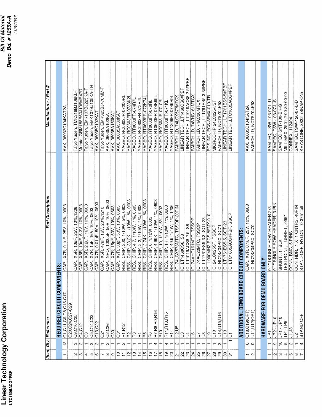
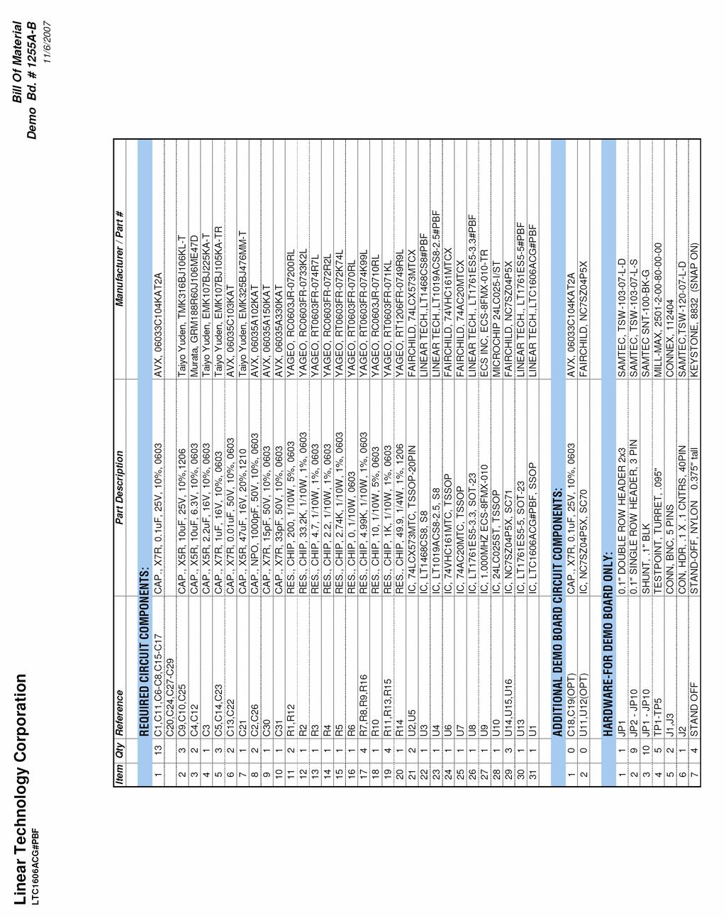
1 DESCRIPTION QUICK START GUIDE FOR DEMONSTRATION CIRCUIT 1255 LTC1605CG/LTC1606CG The LTC1606 is a 250Ksps ADC that draws only 75mW from a single +5V Supply, while the LTC1605 is a 100Ksps ADC that draws only 55mW from a single +5V supply. DC1255 can use either part. The following text refers to the LTC1606 but it also applies to the LTC1605 with appropriate sampling frequency considerations. Demonstration circuit 1255 provides the user a means of evaluating the performance of the LTC1605/LTC1606 and is intended to demonstrate recommended grounding, part placement, routing and bypassing. Design files for this circuit board are available. Call the LTC factory. LTC is a trademark of Linear Technology Corporation Figure1. Connection Diagram 1
2 DC718B QUICK START PROCEDURE Connect DC1255A to a DC718B USB High Speed Data Collection Board using connector J2. Connect DC718B to a host PC with a standard USB A/B cable. Apply 7V- 9V DC to the 7V-9V and GND terminals. Apply +15V and -15V to the indicated terminals, if the internal buffer is to be used (default). Apply a low jitter signal source to J1. As a clock source, either the onboard clock or a low jitter 250kHz 10dBm sine wave or square wave to connector J3 can be used. Note that J3 has a 50 termination resistor to ground. Run the QuickEval-II software (Pscope.exe version K51 or later) supplied with DC718B or download it from Complete software documentation is available from the Help menu. Updates can be downloaded from the Tools menu. Check for updates periodically as new features may be added. The Pscope software should recognize DC1255A and configure itself automatically. Click the Collect button (See Figure 2) to begin acquiring data. Depending on which board was previously used by Pscope, it may be necessary to press Collect a second time. The Collect button then changes to Pause, which can be clicked to stop data acquisition. DC1255 SETUP DC Power DC1255 requires 7-9VDC at approximately 24mA and +/- 15V to power amplifier U3. If you do not use U3 (see jumper JP1) you do not have to provide +/-15V. The 7-9VDC supply powers the ADC through a LT regulator witch provides protection against accidental reverse bias. See Figure 1 for connection details. Clock Source JP10 (CLK) determines whether DC1255 is internally (default) or externally clocked. The internal clock consists of an ECS 1MHz clock oscillator, which is divided by a 74VHC161 counter. This oscillator can be turned off by setting JP9 (OSCEN) to the OFF position. Jumpers (JP4-JP7) set the internal clock divider ratio for the appropriate ADC (LTC1605 or LTC1606). See the table in Figure 1 for jumper settings. For an external clock, you must provide a low jitter 10dBm sine or square wave to J3. Note that J3 has a 50 termination resistor to ground. Driving this input with logic will be difficult. Slow rising edges may compromise SNR of the converter in the presence of high-amplitude higher frequency input signals. The demo board incorporates an edge detector circuit in the form of an inverter (U14) followed by a 200nsec delay, feeding, along with the original clock source, a two input NAND gate (U7B). This will generate an approximate 200nsec active low pulse at the ADC if the clock high time is greater than 200nsec. A 50% duty cycle clock at 250kHz is typically used to test these demo boards. Shorter duty cycle pulses (active High at J3) can be used to a minimum of 40nsec. Data Output Parallel data output from this board (0V-3.3V), if not connected to DC718, can be acquired by a logic analyzer, and subsequently imported into a spreadsheet, or mathematical package depending on what form of digital signal processing is desired. BYTE and CS# Jumpers The demo board is typically shipped with BYTE (JP3) and CS# (JP8) tied to ground. If you intend to operate this device in a fashion that involves these lines, you can use the jumpers as a means of introducing these signals from an external source. Reference JP2 allows you to select an on chip reference or an external LT1019A-2.5 (default) as the reference. The 2
3 typical drift specifications of the external reference are similar to the on chip reference, but the LT has guaranteed maximums. Analog Input The demo board is shipped with JP1 in the IN position, in which case, the input amplifier is in the signal path. With JP1 in the IN position, U3 (LT1468) provides a gain of 9dB. This will allow a signal generator, with a 2.5V RMS output level to drive the converter to full scale. This amplifier does not compromise the SNR or distortion performance of the converter. The input noise density of the LT1468 itself is 5nV/ Hz. In the circuit as configured, the feedback network impedance and the amplifier s input noise current contribute noise power; to produce an input referred noise density of 7.44nV/ Hz. With a gain of 2.82, this produces 17uV RMS of noise in the 675kHz bandwidth imposed by the converter. This is a signal to noise ratio of 112dB at full scale. This is of course not verifiable at the output of the ADC. With JP1 in the OUT position, the input impedance at J1 is 10K. With JP1 in the IN position, the input impedance is very high. If J1 is driven by a generator intended to drive a 50 impedance, you may want to use a 50 throughterminator. If a higher impedance source is to be evaluated, you will see better results with the amplifier in the signal path. If you want to evaluate the amplifier in unity gain, remove R5, or solder a low value resistor in parallel with R16. If you want to evaluate the amplifier with higher gain, you may reduce the value of R5. If you use very high quality resistors, you should be able to increase the gain to 50 before the noise floor of the converter rises discernibly. A voltage gain of 10 should result in the typical SNR of 90dB dropping to 89.9dB. A voltage gain of 50 should give approx 88.7dB, and a gain of 100 would give approximately 86dB SNR. THD will increase but with a gain of 50, the THD of the LT1468 is still typically in the range of -90dB. If the amplifier is configured for high gain, ground potential differences between the various instruments on your bench top may be found to develop a differential component at the input to the demo board. Transformer isolation may be required to produce good results with a gain of 50. Data Collection lection The system used for data collection may have a negative effect on how well the demo board performs, if it produces significant ground current through the demo board. This demo board is tested in house by duplicating the FFT plot shown in the lower left of page 6 of the LTC1606 data sheet. This involves using a low jitter, 250kHz clock source for the encode clock, along with a low noise, low distortion sinusoidal generator at a frequency in the neighborhood of 1KHz. The amplifier is IN for in house test, and the input signal level is approx -1dBfs. The FFT shown in the data sheet is a 4096-point FFT, with the input frequency at precisely Hz. This frequency is coherent (produces an integral number of cycles of the fundamental within the window) for a 250kHz clock frequency, and a prime number of cycles (17 cycles). A prime number of integral cycles exercises the greatest number of possible input codes. Other clock rates require different input frequencies for coherent sampling. To calculate the input frequency f i, for a given sampling frequency f s, number of samples n and prime integer m, use the following formula. There are a number of scenarios that can produce misleading results when evaluating an ADC. One that fi = m * fs n is common is feeding the converter with a frequency, that is a sub-multiple of the sample rate, and which will only exercise a small subset of the possible output codes. Also, note that DC1255 does not have an anti-aliasing filter. Following jumper JP1, is an 800kHz first order low pass filter (R1 and C2). This does not appreciably change the --3dB point of the converter, which is typically 675kHz. Hence, R1 and C2 do not constitute an anti-aliasing filter. If you 3
, and up to and beyond 675KHz they will fold back into the DC-125KHz base band, and become indistinguishable from signals in this")
4 require an anti-aliasing filter in your evaluation, it should generally be placed prior to the LT1468 or any external amplifier in the signal path. If you have frequency components that are above Nyquist (1/2 f s ), and up to and beyond 675KHz they will fold back into the DC-125KHz base band, and become indistinguishable from signals in this band. If you do not have a signal generator capable of ppm levels of frequency accuracy, you can use an FFT with windowing to reduce the leakage or spreading of the fundamental, to get a close approximation of the performance parameters. If an amplifier or clock source with poor phase noise is used, the windowing will not improve the SNR. The signal source typically used for in house testing is a B&K The internal clock source is adequate for most applications. As with any high performance ADC, this part is sensitive to layout. The area immediately surrounding the ADC should be used as a guideline for placement, and routing of the various components associated with the ADC. Note should also be taken of the ground plane used in the layout of this board. Figure 2. DC1255 FastDAACS Screenshot 4
5 5
6 6
7 7
DEMO MANUAL DC2326A LTC /18-Bit, Octal 200ksps, SAR ADC. Description. assembly options
 Description Demonstration circuit 2326A shows the proper way to drive the LTC 2345 ADC. The LTC2345 is a low noise, high speed, simultaneous sampling 16-/18-bit successive approximation register (SAR)
DEMO MANUAL DC2365A LTC2358/LTC2357/ LTC2353/LTC2333: 16-/18-Bit, Octal, Quad and Dual 200ksps/350ksps/550ksps/800ksps SAR ADCs DESCRIPTION
 LTC2358/LTC2357/ LTC2353/LTC2333: 16-/18-Bit, Octal, Quad and Dual 200ksps/350ksps/550ksps/800ksps SAR ADCs DESCRIPTION Demonstration circuit 2365A highlights the LTC 2358 family of buffered input ADCs.
QUICK START GUIDE FOR DEMONSTRATION CIRCUIT /14 BIT 40 TO 105 MSPS ADC
 LTC2207, LTC2207-14, LTC2206, LTC2206-14, LTC2205, LTC2205-14, LTC2204 DESCRIPTION Demonstration circuit 918 supports members of a family of 16/14 BIT 130 MSPS ADCs. Each assembly features one of the following
DEMO CIRCUIT 1057 LT6411 AND LTC2249 ADC QUICK START GUIDE LT6411 High-Speed ADC Driver Combo Board DESCRIPTION QUICK START PROCEDURE
 DESCRIPTION Demonstration circuit 1057 is a reference design featuring Linear Technology Corporation s LT6411 High Speed Amplifier/ADC Driver with an on-board LTC2249 14-bit, 80MSPS ADC. DC1057 demonstrates
QUICK START GUIDE FOR DEMONSTRATION CIRCUIT BIT DIFFERENTIAL INPUT DELTA SIGMA ADC LTC DESCRIPTION
 LTC2433-1 DESCRIPTION Demonstration circuit 745 features the LTC2433-1, a 16-bit high performance Σ analog-to-digital converter (ADC). The LTC2433-1 features 0.12 LSB linearity, 0.16 LSB full-scale accuracy,
DEMO CIRCUIT 1004 ADC DRIVER AND 7X7MM HIGH-PERFORMANCE ADC QUICK START GUIDE ADC Driver and 7x7mm High-Performance ADC DESCRIPTION
 DEMO CIRCUIT 1004 QUICK START GUIDE ADC Driver and 7x7mm High-Performance ADC DESCRIPTION Demonstration circuit 1004 is a reference design featuring Linear Technology Corporation s Analog- Digital Converter
QUICK START GUIDE FOR DEMONSTRATION CIRCUIT 1339 LOW NOISE, 500KSPS, 12-BIT ADC
 LTC0 DESCRIPTION Demonstration circuit features the LTC0 low noise, 00ksps, -Bit, ADC. The LTC0 has an SPI compatible serial interface that can be used to select channel polarity and unipolar or bipolar
DEMO MANUAL DC1563A. LTC2315/LTC2314/LTC2313/LTC2312/ 12-Bit/14-Bit, 5Msps/4.5Msps/ 2.5Msps/500ksps/Serial, High Speed SAR ADCs DESCRIPTION
 LTC2315/LTC2314/LTC2313/LTC2312/ 12-Bit/14-Bit, 5Msps/4.5Msps/ 2.5Msps/500ksps/Serial, High Speed SAR ADCs DESCRIPTION Demonstration circuit 1563A features the LTC 2315 family. With sample rates up to
Reference Clock Distribution for a 325MHz IF Sampling System with over 30MHz Bandwidth, 64dB SNR and 80dB SFDR
 Reference Clock Distribution for a 325MHz IF Sampling System with over 30MHz Bandwidth, 64dB SNR and 80dB SFDR Michel Azarian Clock jitter introduced in an RF receiver through reference clock buffering
DEMO MANUAL DC1437B LTM9003 Digital Predistortion Receiver Subsystem. Description. Connection Diagram
 Description Demonstration circuit 1437B is an evaluation board featuring Linear Technology Corporation s LTM 9003 12-Bit Predistortion Receiver Subsystem. DC1437 demonstrates good circuit layout techniques
DEMO MANUAL DC1925A. LTC /LTC /LTC Bit,1Msps/500ksps/250ksps, Low Power, SAR ADCs with 104dB SNR DESCRIPTION BOARD PHOTO
 DESCRIPTION The LTC 2378-20, LTC2377-20 and LTC2376-20 are 20 bit, low power, low noise SAR ADCs with serial outputs that operate from a single 2.5V supply. The following text refers to the LTC2378-20
QUICK START GUIDE FOR PSCOPE AC DATA COLLECTION AND ANALYSIS SOFTWARE DESCRIPTION
 DESCRIPTION Pscope is a data collection program for use with Linear Technology ADCs. Compatible with DC718B/C, DC890B and DC1371A controllers this software is capable of evaluating such AC specs as SNR,
QUICK START GUIDE FOR DEMONSTRATION CIRCUIT 566 DIGITALLY CONTROLLED PROGRAMMABLE GAIN AMPLIFIER LTC6910 DESCRIPTION
 LTC691 DESCRIPTION Demonstration circuits 566A-A, -B and -C, feature the easy to use, rail-to-rail input and output LTC691 series of Low Noise Programmable Gain Amplifier (PGA) parts. The inverting gain
Enhancing Analog Signal Generation by Digital Channel Using Pulse-Width Modulation
 Enhancing Analog Signal Generation by Digital Channel Using Pulse-Width Modulation Angelo Zucchetti Advantest angelo.zucchetti@advantest.com Introduction Presented in this article is a technique for generating
DEMO MANUAL DC961B LT1994 Low Noise, Low Distortion, Fully Differential Amplifier/Driver. Description
 Description Demonstration circuit 9 features an LT 99, low noise, low distortion, fully differential amplifier. The LT99 is a high precision, very low noise, low distortion, fully differential input/output
DEMO MANUAL DC2135A. LTC ppm Linearity, DC Accurate Driver. Description
 Description Demonstration circuit 2135A shows a simple DC accurate ADC driver circuit that converts a ±10V single-ended input signal into a fully differential signal capable of driving the LTC2378-20 with
How to drive the LTC2387 ( part I )
") How to drive the LTC2387 ( part I ) Signal Applications to 5 MHz that require low inter-modulation distortion The biggest challenge in driving a 15 Msps, 18 bit ADC with an 8Vp-p input range is the lack
How to drive the LTC2387 ( part I ) Signal Applications to 5 MHz that require low inter-modulation distortion The biggest challenge in driving a 15 Msps, 18 bit ADC with an 8Vp-p input range is the lack
EVDP610 IXDP610 Digital PWM Controller IC Evaluation Board
 IXDP610 Digital PWM Controller IC Evaluation Board General Description The IXDP610 Digital Pulse Width Modulator (DPWM) is a programmable CMOS LSI device, which accepts digital pulse width data from a
QUICK START GUIDE FOR DEMONSTRATION CIRCUIT 678A 40MHZ TO 900MHZ DIRECT CONVERSION QUADRATURE DEMODULATOR
 DESCRIPTION QUICK START GUIDE FOR DEMONSTRATION CIRCUIT 678A LT5517 Demonstration circuit 678A is a 40MHz to 900MHz Direct Conversion Quadrature Demodulator featuring the LT5517. The LT 5517 is a direct
Laboratory Experiment #1 Introduction to Spectral Analysis
 J.B.Francis College of Engineering Mechanical Engineering Department 22-403 Laboratory Experiment #1 Introduction to Spectral Analysis Introduction The quantification of electrical energy can be accomplished
Demo Circuit DC550A Quick Start Guide.
 May 12, 2004 Demo Circuit DC550A. Introduction Demo circuit DC550A demonstrates operation of the LT5514 IC, a DC-850MHz bandwidth open loop transconductance amplifier with high impedance open collector
ADQ214. Datasheet. Features. Introduction. Applications. Software support. ADQ Development Kit. Ordering information
 ADQ214 is a dual channel high speed digitizer. The ADQ214 has outstanding dynamic performance from a combination of high bandwidth and high dynamic range, which enables demanding measurements such as RF/IF
24-Bit, 312 ksps, 109 db Sigma-Delta ADC with On-Chip Buffers and Serial Interface AD7764
 24-Bit, 312 ksps, 19 db Sigma-Delta ADC with On-Chip Buffers and Serial Interface AD7764 FEATURES High performance 24-bit - ADC 115 db dynamic range at 78 khz output data rate 19 db dynamic range at 312
M1 SHDN CS CONVST RD WR DIFF A2 A1 A0 UNI/BIP PGA M0 OV DD CONTROL LOGIC AND PROGRAMMABLE SEQUENCER
 FEATURES Flexible 8-Channel Multiplexer Single-Ended or Differential Inputs Two Gain Ranges Plus Unipolar and Bipolar Operation 1.25Msps Sampling Rate Single 5V Supply and 4mW Power Dissipation Scan Mode
Eliminate Pipeline Headaches with New 12-Bit 3Msps SAR ADC by Dave Thomas and William C. Rempfer
 A new 12-bit 3Msps ADC brings new levels of performance and ease of use to high speed ADC applications. By raising the speed of the successive approximation (SAR) method to 3Msps, it eliminates the many
PARAMETER CONDITIONS TYPICAL PERFORMANCE Operating Supply Voltage 3.1V to 3.5V Supply Current V CC = 3.3V, LO applied 152mA
 DESCRIPTION LT5578 Demonstration circuit 1545A-x is a high linearity upconverting mixer featuring the LT5578. The LT 5578 is a high performance upconverting mixer IC optimized for output frequencies in
MAX1002/MAX1003 Evaluation Kits
 9-50; Rev 0; 6/97 MAX00/MAX00 Evaluation Kits General Description The MAX00/MAX00 evaluation kits (EV kits) simplify evaluation of the 60Msps MAX00 and 90Msps MAX00 dual, 6-bit analog-to-digital converters
Advanced Lab LAB 6: Signal Acquisition & Spectrum Analysis Using VirtualBench DSA Equipment: Objectives:
 Advanced Lab LAB 6: Signal Acquisition & Spectrum Analysis Using VirtualBench DSA Equipment: Pentium PC with National Instruments PCI-MIO-16E-4 data-acquisition board (12-bit resolution; software-controlled
APPLICATION NOTE 3942 Optimize the Buffer Amplifier/ADC Connection
 Maxim > Design Support > Technical Documents > Application Notes > Communications Circuits > APP 3942 Maxim > Design Support > Technical Documents > Application Notes > High-Speed Interconnect > APP 3942
Selecting and Using High-Precision Digital-to-Analog Converters
 Selecting and Using High-Precision Digital-to-Analog Converters Chad Steward DAC Design Section Leader Linear Technology Corporation Many applications, including precision instrumentation, industrial automation,
DEMO MANUAL DC777A LTC Bit Rail-to-Rail V OUT DAC DESCRIPTION PERFORMANCE SUMMARY
 LTC2601 16-Bit Rail-to-Rail V OUT DAC DESCRIPTION Demonstration circuit DC777A features the LTC 2601 16-bit DAC. This device establishes a new board-density benchmark for 16-bit DACs and advances performance
SHF Communication Technologies AG. Wilhelm-von-Siemens-Str. 23D Berlin Germany. Phone Fax
 SHF Communication Technologies AG Wilhelm-von-Siemens-Str. 23D 12277 Berlin Germany Phone ++49 30 772 051-0 Fax ++49 30 753 10 78 E-Mail: sales@shf.de Web: http://www.shf.de Datasheet SHF D837 A Differential
SHF Communication Technologies AG
 SHF Communication Technologies AG Wilhelm-von-Siemens-Str. 23D 12277 Berlin Germany Phone +49 30 772051-0 Fax +49 30 7531078 E-Mail: sales@shf.de Web: http://www.shf.de Datasheet SHF 78120 D Synthesized
Maxim Integrated Products 1
 9-958; Rev 0; 7/0 MAX9 Evaluation Kit General Description The MAX9 evaluation kit (EV kit) is a fully assembled and tested circuit board that contains all the components necessary to evaluate the performance
Using High Speed Differential Amplifiers to Drive Analog to Digital Converters
 Using High Speed Differential Amplifiers to Drive Analog to Digital Converters Selecting The Best Differential Amplifier To Drive An Analog To Digital Converter The right high speed differential amplifier
DEMO MANUAL DC941A LTC Bit Σ ADC with Easy Drive Input Current Cancellation. Description. Quick Start Procedure
 Description Demonstration circuit 9A features the LTC, a -bit high performance Δ analog-to-digital converter (ADC). The LTC features ppm linearity, 0.μV offset, and 00nV RMS noise. The input is fully differential,
Optical Power Meter Basics
 Optical Power Meter Basics Introduction An optical power meter measures the photon energy in the form of current or voltage from an optical detector such as a semiconductor, a thermopile, or a pyroelectric
Low Noise Oscillator series LNO 4800 B MHz
 Specific request can be addressed to RAKON hirel@rakon.com Product Description LNO 4800 B3 is a low noise oscillator generating an output signal at 4800 MHz. It is composed by an OCSO (Oven Controlled
FYS3240 PC-based instrumentation and microcontrollers. Signal sampling. Spring 2017 Lecture #5
 FYS3240 PC-based instrumentation and microcontrollers Signal sampling Spring 2017 Lecture #5 Bekkeng, 30.01.2017 Content Aliasing Sampling Analog to Digital Conversion (ADC) Filtering Oversampling Triggering
OPVibr Ultrasonic vibration measurement system Ultrasonic vibrometer INSTRUCTION MANUAL
 Przedsiębiorstwo Badawczo-Produkcyjne OPTEL Sp. z o.o. ul. Morelowskiego 30 PL-52-429 Wrocław tel.: +48 (071) 329 68 54 fax.: +48 (071) 329 68 52 e-mail: optel@optel.pl http://www.optel.pl Wrocław, 2015.11.04
DEMO MANUAL DC579A LTC2600 Octal 16-Bit DAC DESCRIPTION PERFORMANCE SUMMARY BOARD PHOTO
 LTC2600 Octal 16-Bit DAC DESCRIPTION Demonstration circuit 579A features the LTC2600 octal 16-bit DAC. This device establishes a new board density benchmark for 16-bit DACs and advances performance standards
Keywords: GPS, receiver, GPS receiver, MAX2769, 2769, 1575MHz, Integrated GPS Receiver, Global Positioning System
 Maxim > Design Support > Technical Documents > User Guides > APP 3910 Keywords: GPS, receiver, GPS receiver, MAX2769, 2769, 1575MHz, Integrated GPS Receiver, Global Positioning System USER GUIDE 3910 User's
1.0 Introduction to VirtualBench
 Table of Contents 1.0 Introduction to VirtualBench... 3 1. 1 VirtualBench in the Laboratory... 3 1.2 VirtualBench Specifications... 4 1.3 Introduction to VirtualBench Getting Started Guide Lab Exercises...
Micropower, Single-Supply, Rail-to-Rail, Precision Instrumentation Amplifiers MAX4194 MAX4197
 General Description The is a variable-gain precision instrumentation amplifier that combines Rail-to-Rail single-supply operation, outstanding precision specifications, and a high gain bandwidth. This
LNS ultra low phase noise Synthesizer 8 MHz to 18 GHz
 LNS ultra low phase noise Synthesizer 8 MHz to 18 GHz Datasheet The LNS is an easy to use 18 GHz synthesizer that exhibits outstanding phase noise and jitter performance in a 3U rack mountable chassis.
V CC OUT MAX9945 IN+ V EE
 19-4398; Rev ; 2/9 38V, Low-Noise, MOS-Input, General Description The operational amplifier features an excellent combination of low operating power and low input voltage noise. In addition, MOS inputs
Laboratory #4: Solid-State Switches, Operational Amplifiers Electrical and Computer Engineering EE University of Saskatchewan
 Authors: Denard Lynch Date: Oct 24, 2012 Revised: Oct 21, 2013, D. Lynch Description: This laboratory explores the characteristics of operational amplifiers in a simple voltage gain configuration as well
Simultaneous Co-Test of High Performance DAC-ADC Pairs May 13-28
 Simultaneous Co-Test of High Performance DAC-ADC Pairs Adviser & Client Members Luke Goetzke Ben Magstadt Tao Chen Aug, 2012 May, 2013 1 Agenda Project Description Project Design Test and Debug Results
QUICK START GUIDE FOR DEMONSTRATION CIRCUIT 1455A 5MHZ TO 1600MHZ HIGH LINEARITY DIRECT QUADRATURE MODULATOR LTC5598 DESCRIPTION
 LTC5598 DESCRIPTION Demonstration circuit 1455A is a high linearity direct quadrature modulator featuring the LTC5598. The LTC 5598 is a direct I/Q modulator designed for high performance wireless applications,
Model 305 Synchronous Countdown System
 Model 305 Synchronous Countdown System Introduction: The Model 305 pre-settable countdown electronics is a high-speed synchronous divider that generates an electronic trigger pulse, locked in time with
SHF Communication Technologies AG. Wilhelm-von-Siemens-Str. 23D Berlin Germany. Phone Fax
 SHF Communication Technologies AG Wilhelm-von-Siemens-Str. 23D 12277 Berlin Germany Phone +49 30 772 051-0 Fax +49 30 753 10 78 E-Mail: sales@shf-communication.com Web: www.shf-communication.com Datasheet
Dual-Channel Modulator ADM0D79*
 a Dual-Channel Modulator ADM0D79* FEATURES High-Performance ADC Building Block Fifth-Order, 64 Times Oversampling Modulator with Patented Noise-Shaping Modulator Clock Rate to 3.57 MHz 103 db Dynamic Range
LT MHz, 30V/µs 16-Bit Accurate A V 2 Op Amp. Description. Features. Applications. Typical Application
 Features n Stable in Gain A (A = ) n MHz Gain Bandwidth Product n /μs Slew Rate n Settling Time: 8ns ( Step, ) n Specified at and Supplies n Low Distortion, 9.dB for khz, P-P n Maximum Input Offset oltage:
SHF Communication Technologies AG. Wilhelm-von-Siemens-Str. 23D Berlin Germany. Phone Fax
 SHF Communication Technologies AG Wilhelm-von-Siemens-Str. 23D 12277 Berlin Germany Phone ++49 30 772 051-0 Fax ++49 30 753 10 78 E-Mail: sales@shf.de Web: http://www.shf.de Datasheet SHF D836 A Differential
GFT bit High Speed Digitizer
 FEATURES Up to 4 analog channels in only 1U space Up to 2GS/s sampling rate per channel 14 bits vertical resolution DC coupled with up to 1GHz bandwidth Programmable DC offset Internal and external clock
AD9772A - Functional Block Diagram
 F FEATURES single 3.0 V to 3.6 V supply 14-Bit DAC Resolution 160 MPS Input Data Rate 67.5 MHz Reconstruction Passband @ 160 MPS 74 dbc FDR @ 25 MHz 2 Interpolation Filter with High- or Low-Pass Response
XR-2206 Monolithic Function Generator
 ...the analog plus company TM XR-0 Monolithic Function Generator FEATURES Low-Sine Wave Distortion 0.%, Typical Excellent Temperature Stability 0ppm/ C, Typical Wide Sweep Range 000:, Typical Low-Supply
Tiny 12-Bit ADC Delivers 2.2Msps Through 3-Wire Serial Interface by Joe Sousa Introduction
 DESIGN FETURES Tiny -Bit DC Delivers.Msps Through -Wire Serial Interface by Joe Sousa Introduction LTC Serial interfaces occupy little routing space, but usually limit the speed of an DC. The LTC has a
Experiments #7. Operational Amplifier part 1
 Experiments #7 Operational Amplifier part 1 1) Objectives: The objective of this lab is to study operational amplifier (op amp) and its applications. We will be simulating and building some basic op-amp
THE NEXT GENERATION AIRBORNE DATA ACQUISITION SYSTEMS. PART 1 - ANTI-ALIASING FILTERS: CHOICES AND SOME LESSONS LEARNED
 THE NEXT GENERATION AIRBORNE DATA ACQUISITION SYSTEMS. PART 1 - ANTI-ALIASING FILTERS: CHOICES AND SOME LESSONS LEARNED Item Type text; Proceedings Authors Sweeney, Paul Publisher International Foundation
QUICK START GUIDE FOR DEMONSTRATION CIRCUIT 804 POWER OVER ETHERNET PD INTERFACE WITH INTEGRATED SWITCHING REGULATOR
 DESCRIPTION LTC4267 Demonstration circuit 804 is a POWER OVER ETHERNET PD INTERFACE WITH INTEGRATED SWITCHING REGULATOR featuring the LTC4267. It provides a complete IEEE 802.3af power device (PD) interface
CLC Bit, 52 MSPS A/D Converter
 14-Bit, 52 MSPS A/D Converter General Description The is a monolithic 14-bit, 52 MSPS analog-to-digital converter. The ultra-wide dynamic range and high sample rate of the device make it an excellent choice
DIGITAL UTILITY SUB- SYSTEMS
 DIGITAL UTILITY SUB- SYSTEMS INTRODUCTION... 138 bandpass filters... 138 digital delay... 139 digital divide-by-1, 2, 4, or 8... 140 digital divide-by-2, 3, 4... 140 digital divide-by-4... 141 digital
QUICK START GUIDE FOR DEMONSTRATION CIRCUIT 543 LTC2920 WITH DUAL DC TO DC CONVERTER
 DESCRIPTION QUICK START GUIDE FOR DEMONSTRATION CIRCUIT 543 LTC2920-2 Demonstration circuit 543 is an LTC 2920-2 Dual Voltage Margining Controller integrated with an LTC1628 Dual High Efficiency, 2-Phase
LabMaster Series TECHNOLOGIES. Unistep LabMaster Series PLL LOOP MODULE USER MANUAL. Copyright Unistep Technologies
 TECHNOLOGIES LabMaster Series Unistep LabMaster Series PLL PHASE-LOCK LOOP MODULE USER MANUAL Copyright 2010 - Unistep Technologies User Manual PLL Phase-Lock Loop Module 2 PLL ~~~ PHASE--LLOCK LLOOP MODULLE
SAMPULSE50GHz and SAMPULSE70GHzANT PULSER/SAMPLER DEMO BOARD
 SAMPULSE50GHz and SAMPULSE70GHzANT PULSER/SAMPLER DEMO BOARD REV B. PRELIMINARY USER MANUAL 2/25/15 Figure 1. Connections to SAMPULSE50GHz (left) or SAMPULSE70GHzANT (right). INTRODUCTION: The SAMPULSE50GHz
LM2462 Monolithic Triple 3 ns CRT Driver
 LM2462 Monolithic Triple 3 ns CRT Driver General Description The LM2462 is an integrated high voltage CRT driver circuit designed for use in color monitor applications. The IC contains three high input
4-Channel, Simultaneous Sampling, High Speed, 12-Bit ADC AD7864
 FEATURES High Speed (1.65 s) 12-Bit ADC 4 Simultaneously Sampled Inputs 4 Track/Hold Amplifiers 0.35 s Track/Hold Acquisition Time 1.65 s Conversion Time per Channel HW/SW Select of Channel Sequence for
Single Conversion LF Upconverter Andy Talbot G4JNT Jan 2009
 Single Conversion LF Upconverter Andy Talbot G4JNT Jan 2009 Mark 2 Version Oct 2010, see Appendix, Page 8 This upconverter is designed to directly translate the output from a soundcard from a PC running
Design Implementation Description for the Digital Frequency Oscillator
 Appendix A Design Implementation Description for the Frequency Oscillator A.1 Input Front End The input data front end accepts either analog single ended or differential inputs (figure A-1). The input
ericssonz LBI-38640E MAINTENANCE MANUAL FOR VHF TRANSMITTER SYNTHESIZER MODULE 19D902780G1 DESCRIPTION
 MAINTENANCE MANUAL FOR VHF TRANSMITTER SYNTHESIZER MODULE 19D902780G1 TABLE OF CONTENTS Page DESCRIPTION........................................... Front Cover GENERAL SPECIFICATIONS...................................
Overall Accuracy = ENOB (Effective Number of Bits)
") Overall Accuracy = ENOB (Effective Number of Bits) In choosing a data acquisition board, there is probably no more important specification than its overall accuracy that is, how closely the output data
Overall Accuracy = ENOB (Effective Number of Bits) In choosing a data acquisition board, there is probably no more important specification than its overall accuracy that is, how closely the output data
Differential Amplifiers
 Differential Amplifiers Benefits of Differential Signal Processing The Benefits Become Apparent when Trying to get the Most Speed and/or Resolution out of a Design Avoid Grounding/Return Noise Problems
PC-based controller for Mechatronics System
 Course Code: MDP 454, Course Name:, Second Semester 2014 PC-based controller for Mechatronics System Mechanical System PC Controller Controller in the Mechatronics System Configuration Actuators Power
5 V, 12-Bit, Serial 220 ksps ADC in an 8-Lead Package AD7898 * REV. A
 a FEATURES Fast 12-Bit ADC with 220 ksps Throughput Rate 8-Lead SOIC Single 5 V Supply Operation High Speed, Flexible, Serial Interface that Allows Interfacing to 3 V Processors On-Chip Track/Hold Amplifier
LM2412 Monolithic Triple 2.8 ns CRT Driver
 Monolithic Triple 2.8 ns CRT Driver General Description The is an integrated high voltage CRT driver circuit designed for use in high resolution color monitor applications. The IC contains three high input
Single-Phase Grid-Tied Inverter (PWM Rectifier/Inverter)
") Exercise 2 Single-Phase Grid-Tied Inverter (PWM Rectifier/Inverter) EXERCISE OBJECTIVE When you have completed this exercise, you will be familiar with the singlephase grid-tied inverter. DISCUSSION OUTLINE
Exercise 2 Single-Phase Grid-Tied Inverter (PWM Rectifier/Inverter) EXERCISE OBJECTIVE When you have completed this exercise, you will be familiar with the singlephase grid-tied inverter. DISCUSSION OUTLINE
MAX3503/MAX3505 Evaluation Kits
 19-2504; Rev 0; 7/02 MAX3503/MAX3505 Evaluation Kits General Description The MAX3503/MAX3505 evaluation kits (EV kits) simplify evaluation of the MAX3503 and MAX3505 CATV upstream amplifiers. The kits
LTC Bit, 20Msps Low Noise Dual ADC FEATURES DESCRIPTION APPLICATIONS TYPICAL APPLICATION
 16-Bit, 2Msps Low Noise Dual ADC FEATURES n Two-Channel Simultaneously Sampling ADC n 84.1dB SNR (46μV RMS Input Referred Noise) n 99dB SFDR n ±2.3LSB INL(Max) n Low Power: 16mW Total, 8mW per Channel
UCE-DSO212 DIGITAL OSCILLOSCOPE USER MANUAL. UCORE ELECTRONICS
 UCE-DSO212 DIGITAL OSCILLOSCOPE USER MANUAL UCORE ELECTRONICS www.ucore-electronics.com 2017 Contents 1. Introduction... 2 2. Turn on or turn off... 3 3. Oscilloscope Mode... 4 3.1. Display Description...
Arbitrary/Function Waveform Generators 4075B Series
 Data Sheet Arbitrary/Function Waveform Generators Point-by-Point Signal Integrity The Arbitrary/Function Waveform Generators are versatile high-performance single- and dual-channel arbitrary waveform generators
How to turn an ADC into a DAC: A 110dB THD, 18mW DAC using sampling of the output and feedback to reduce distortion
 How to turn an ADC into a DAC: A 110dB THD, 18mW DAC using sampling of the output and feedback to reduce distortion Axel Thomsen, Design Manager Silicon Laboratories Inc. Austin, TX 1 Why this talk? A
V CC OUT MAX9945 IN+ V EE
 19-4398; Rev 1; 12/ 38V, Low-Noise, MOS-Input, General Description The operational amplifier features an excellent combination of low operating power and low input voltage noise. In addition, MOS inputs
LM48821 Evaluation Board User's Guide
 National Semiconductor Application Note 1589 Kevin Hoskins May 2007 Quick Start Guide from the two amplifiers found on pins OUTR and OUTL, respectively. Apply power. Make measurements. Plug in a pair of
PHYSICS 330 LAB Operational Amplifier Frequency Response
 PHYSICS 330 LAB Operational Amplifier Frequency Response Objectives: To measure and plot the frequency response of an operational amplifier circuit. History: Operational amplifiers are among the most widely
DEMO MANUAL DC573A LTC Bit Micropower No Latency Delta Sigma ADC DESCRIPTION BOARD PHOTO
 DESCRIPTION This demonstration board features the LTC 00, a -bit high performance ΔΣ analog-to-digital converter (ADC). The LTC00 combines exemplary DC accuracy (INL ±ppm,.μv offset, 0.ppm noise) with
Tiny, 2.1mm x 1.6mm, 3Msps, Low-Power, Serial 12-Bit ADC
 EVALUATION KIT AVAILABLE MAX1118 General Description The MAX1118 is a tiny (2.1mm x 1.6mm), 12-bit, compact, high-speed, low-power, successive approximation analog-to-digital converter (ADC). This high-performance
AN-742 APPLICATION NOTE
 APPLICATION NOTE One Technology Way P.O. Box 9106 Norwood, MA 02062-9106, U.S.A. Tel: 781.329.4700 Fax: 781.461.3113 www.analog.com Frequency Domain Response of Switched-Capacitor ADCs by Rob Reeder INTRODUCTION
DESCRIPTIO. LTC Low Power, 8th Order Progressive Elliptic, Lowpass Filter
 LTC9- Low Power, th Order Progressive Elliptic, Lowpass Filter FEATRES th Order Elliptic Filter in SO- Package Operates from Single.V to ±V Power Supplies db at.f CTOFF db at.f CTOFF db at f CTOFF Wide
CHAPTER 7 HARDWARE IMPLEMENTATION
 168 CHAPTER 7 HARDWARE IMPLEMENTATION 7.1 OVERVIEW In the previous chapters discussed about the design and simulation of Discrete controller for ZVS Buck, Interleaved Boost, Buck-Boost, Double Frequency
150V, 1.5A, Unipolar Ultrasound Pulser Demoboard +5.0V VLL AVDD PWR VSS VDD VPP CWD VDD VDD VDD. Q[7:0] Data Latch. Shift Register D0 SDI SUB VSUB
![150V, 1.5A, Unipolar Ultrasound Pulser Demoboard +5.0V VLL AVDD PWR VSS VDD VPP CWD VDD VDD VDD. Q[7:0] Data Latch. Shift Register D0 SDI SUB VSUB](/thumbs/88/116190510.jpg "150V, 1.5A, Unipolar Ultrasound Pulser Demoboard +5.0V VLL AVDD PWR VSS VDD VPP CWD VDD VDD VDD. Q[7:0] Data Latch. Shift Register D0 SDI SUB VSUB") 5V,.5A, Unipolar Ultrasound Pulser Demoboard General Description The HV755 is a monolithic eight-channel, high-speed, high voltage, unipolar ultrasound transmitter pulser. This integrated, high performance
5V,.5A, Unipolar Ultrasound Pulser Demoboard General Description The HV755 is a monolithic eight-channel, high-speed, high voltage, unipolar ultrasound transmitter pulser. This integrated, high performance
Workshop ESSCIRC. Low-Power Data Acquisition System For Very Small Signals At Low Frequencies With12-Bit- SAR-ADC. 17. September 2010.
 Workshop ESSCIRC Low-Power Data Acquisition System For Very Small Signals At Low Frequencies With12-Bit- SAR-ADC 17. September 2010 Christof Dohmen Outline System Overview Analog-Front-End Chopper-Amplifier
16-Bit, Low-Power, 2-Channel, Sigma-Delta ADC MX7705
 General Description The MX7705 low-power, 2-channel, serial-output analog-to-digital converter (ADC) includes a sigma-delta modulator with a digital filter to achieve 16-bit resolution with no missing
8-/4-/2-Channel, 14-Bit, Simultaneous-Sampling ADCs with ±10V, ±5V, and 0 to +5V Analog Input Ranges
 19-3157; Rev 4; 10/08 8-/4-/2-Channel, 14-Bit, Simultaneous-Sampling ADCs General Description The MAX1316 MAX1318/MAX1320 MAX1322/MAX1324 MAX1326 14-bit, analog-to-digital converters (ADCs) offer two,
781/ /
 781/329-47 781/461-3113 SPECIFICATIONS DC SPECIFICATIONS J Parameter Min Typ Max Units SAMPLING CHARACTERISTICS Acquisition Time 5 V Step to.1% 25 375 ns 5 V Step to.1% 2 35 ns Small Signal Bandwidth 15
DATASHEET HI5805. Features. Applications. Ordering Information. Pinout. 12-Bit, 5MSPS A/D Converter. FN3984 Rev 7.00 Page 1 of 12.
 12-Bit, 5MSPS A/D Converter NOT RECOMMENDED FOR NEW DESIGNS NO RECOMMENDED REPLACEMENT contact our Technical Support Center at 1-888-INTERSIL or www.intersil.com/tsc DATASHEET FN3984 Rev 7.00 The HI5805
Very Low Distortion, Precision Difference Amplifier AD8274
 Very Low Distortion, Precision Difference Amplifier AD8274 FEATURES Very low distortion.2% THD + N (2 khz).% THD + N ( khz) Drives Ω loads Excellent gain accuracy.3% maximum gain error 2 ppm/ C maximum
Sallen-Key_High_Pass_Filter -- Overview
 Sallen-Key_High_Pass_Filter -- Overview Sallen-Key High Pass Filter Objectives: After performing this lab exercise, learner will be able to: Understand & analyze working of Sallen-Key topology of active
Sampling and Reconstruction
 Experiment 10 Sampling and Reconstruction In this experiment we shall learn how an analog signal can be sampled in the time domain and then how the same samples can be used to reconstruct the original
LT Dual 200MHz, 30V/µs 16-Bit Accurate A V 2 Op Amp DESCRIPTION FEATURES APPLICATIONS TYPICAL APPLICATION
 FEATURES n Stable in Gain A (A = ) n MHz Gain Bandwidth Product n /μs Slew Rate n Settling Time: 8ns (μ, Step) n Specifi ed at and Supplies n Maximum Input Offset oltage: μ n Low Distortion: 9. for khz,