OPERATORS MANUAL. Klark Teknik Group, Klark Teknik Building, Walter Nash Road, Kidderminster. Worcestershire. DY11 7HJ. England.
|
|
|
- Maurice Gordon
- 6 years ago
- Views:
Transcription

1 OPERATORS MANUAL Klark Teknik Group, Klark Teknik Building, Walter Nash Road, Kidderminster. Worcestershire. DY11 7HJ. England. Tel: Fax: Website: midasconsoles.com
2
3 IMPORTANT SAFETY INSTRUCTIONS CAUTION RISK OF ELECTRIC SHOCK DO NOT OPEN WARNING: TO REDUCE THE RISK OF FIRE OR ELECTRIC SHOCK, DO NOT EXPOSE THIS APPLIANCE TO RAIN OR MOISTURE AVIS: RISQUÉ DE CHOC ELETRIQUE. NE PAS OUVRIR These symbols are internationally accepted symbols that warn of potential hazards with electrical products. The lightning flash with arrowhead symbol, within an equilateral triangle is intended to alert the user to the presence of uninsulated dangerous voltage within the product's enclosure that may be of sufficient magnitude to constitute a risk of electric shock to persons. The exclamation point within an equilateral triangle is intended to alert the user to the presence of important operating and maintenance (servicing) instructions in the literature accompanying the appliance. 1. Read these instructions. 2. Keep these instructions.. Heed all warnings. 4. Follow all instructions.. Do not use this apparatus near water.. Clean only with a dry cloth. 7. Do not block any of the ventilation openings. Install in accordance with the manufacturers instructions. 8. Do not install near any heat sources such as radiators, heat registers, stoves, or other apparatus that produce heat.. Do not defeat the safety purpose of the polarized or grounding-type plug. A polarized plug has two blades with one wider than the other. A grounding type plug has two blades and a third grounding prong. The wide blade or third prong are provided for your safety. When the provided plug does not fit into your outlet, consult an electrician for replacement of the obsolete outlet. 1. Protect the power cord from being walked on or pinched particularly at plugs, convenience receptacles, and the point where they exit from the apparatus. 11. Unplug this apparatus during lightning storms or when unused for long periods of time.. Refer all testing to qualified personnel. Servicing is required when the apparatus is damaged in any way, such as power-supply cord or plug is damaged, liquid has been spilled or objects have fallen into the apparatus, the apparatus has been exposed to rain or moisture, does not operate normally, or has been dropped.
4
5 Walter Nash Road, Kidderminster, Worcestershire. DY11 7HJ. England Tel: (44) () Fax: (44) () Company Registration No: 2414 SIGNAL PROCESSING BY DEFINITION DESIGNEDFORAPUREPERFORMANCE DECLARATION OF CONFORMITY We, of, Klark Teknik Group (UK) Plc Klark Teknik Building, Walter Nash Road, Kidderminster, Worcestershire, DY11 7HJ. Declare that a sample of the following product:- Product Type Number Product Description Nominal Voltage (s) Current Freq Legend Professional Audio 11V AC.A /Hz Mixing Desk 2V AC 2.A to which this declaration refers, is in conformity with the following directives and/or standards:- Directive(s) Generic Standard using EN1 Limits and Methods Class B Conduct Emissions Class B Radiated Emissions Fast Transient Bursts Static Discharge Basic Electrical Safety LVD Harmonics Flicker Test Standard(s) EN81/2 EN1 EN1 EN1-4-4 EN1-4-2 EN24 EN EN1--2 EN1-- Signed:... th Date: 1 March 22 Name: David Hoare Authority: Technical Director, Klark Teknik Group (UK) Plc Attention! Where applicable, the attention of the specifier, purchaser, installer or user is drawn to special limitations of use which must be observed when these products are taken into service to maintain compliance with the above directives. Details of these special measures and limitations to use are available on request and are available in product manuals. A Subsidiary of Telex communications, Inc.
6
7 ATTENTION! The following special limitations apply to the console and must be observed in order to maintain safety and electromagnetic compatibility performance: POWER CONNECTION The console should only be operated with the power supply connected to ground via its mains supply connector. CONTROL CONNECTIONS The console should only be operated with high quality screened control cables. All connector shells should be of metal construction so that they provide a screen when they are plugged into the console. All ground connections should be made as shown on the connections page (over leaf). AUDIO CONNECTIONS The console should only be operated with high quality screened twisted pair audio cables. All connector shells should be of metal construction so that they provide a screen when they are plugged into the console. All ground connections should be made as shown on the connections page (over leaf). ELECTRIC FIELDS If the console is operated in an electromagnetic field that is amplitude modulated by an audio frequency signal, the signal to noise ratio may be degraded. Degradation of up to db may be experienced under extreme conditions (V/m, % modulation). INSTALLATION There are a number of points to consider when installing a mixing console. Many of these points will have been addressed before the console is even unpacked but it is worth repeating them. POSITION The console should be located in a convenient space commensurate with the use to which the console is being put. Ideally a cool area is preferred not in close proximity to power distribution equipment or other potential sources of interference. Provision should be made for some flat surface surrounding the console to prevent people using it as a table top. POWER The power supply should be located as far from the console as the connecting cable will allow. It should be set for the appropriate line voltage and plugged into the mains outlets using the supplied cables. THE POWER SUPPLY SHOULD NEVER BE OPERATED WITH THE MAINS EARTH DISCONNECTED Please note that the power supply contains LETHAL VOLTAGES greatly in excess of the mains voltage and that its rails can produce extremely large currents which could burn out equipment and wiring if shorted. All testing and servicing should ONLY be carried out by qualified engineers.

8 LEGEND CONNECTORS Terminator Consoles can be linked using the Midas Can Bus. Depressing the terminator defines the end of the chain and prevents any possible unwanted signal being sent back up the chain. CAN BUSS Midas Can Bus Pin 1: +V (1mA max) Pin 2: Can low Pin : OV Can Pin 4: Can High Pin : -V(1mA max) MIDI In Pin 2: Ground Pin 4: In+ Pin : In- THROU IN OUT MIDI Thru Pin 2: Ground Pin 4: In+ Pin : In- MIDI Out Pin 2: Ground Pin 4: In+ Pin : In- RS-22 Pin 2: Receive Data Pin : Transmit Data Pin : GND Input Send / Return Tip: Hot Ring: Cold Sleeve: Ground Input / Output XLR Pin 1: Ground Pin 2: Hot Pin : Cold Way Edac Connector (see page 41for wiring details)
9 CONTENTS Midas L1 Mono Input Module Input Pod FOH EQ MON EQ Midas L11Mix Output Module Meter Section Talk Back Section Mix Section VCA Master Section Midas L21 Master Module Aux Return Section Group Section Matrix Section Automation Central Control Section Assign Keys and Mode Switches Snapshot Automation System Monitor Section Master Section Automation System Control Automation System System Layout Menu Overview V1.1 Lock States Assign Functions Assigning Automutes to FOH Assigning Automutes to MON Frame layout and Measurements Rear Panel Configuration Edac Wiring Diagram Block Diagrams Overview and Statistics Midas L7 Power Supply Input Crib Sheet Page 1 Page 2 Page Page 4 Page Page 1 Page 11 Page 1 Page Page 1 Page 2 Page 24 Page 2 Page 27 Page 28 Page 1 Page 2 Page Page 4 Page Page Page 7 Page 8 Page Page 4 Page Page 4 Page Page 8 Page 74
10
11 O PAD 48V gain only r c lcr l stereo pan image treble hi-pass hi-mid hi-mid 2 lo-mid lo-mid 2 bass insert post k k 1k 2k 4 1k k 8k 1 1k 2k k 4k 1k 2 4 2k front of house monitor SOLO PRE PRE PRE PRE PRE PRE MON MON MON FOH MON EQ EQ ST MONO SIS PAN Midas L1 Mono Input Module db f.o.h. monitor SET
12 Input Pod The 48V switch connects 48 volt phantom power to the XLR mic input connector. This is suitable for a condenser microphone or DI box. A parallel line input is also provided via a jack which is protected from application of 48V. The PAD switch gives db of attenuation to the input signal which will allow the connection of high output microphones or line level signals. There is a global disable for the 48V on the Talk Back section -see page. Note:- Connecting a jack plug disconnects the XLR input. 48V PAD The PHASE switch activates a degrees phase change within the input amplifier. The GAIN control gives continuous adjustment of the input amplifier gain from + 1dB to + db. O gain + The METER monitors the peak signal level of the main (FOH) input channel pre fader signal path. 2
13 FOH EQ The HI PASS filter control is continuously adjustable from 2Hz to 4Hz. hi-pass 1 The HI PASS switch connects the filter in the input channel signal path before the insert point and equaliser. NOTE:- the signal path beyond this point is split into two - FOH and MON. The MON switch connects the treble EQ to operate in the monitor signal path as well as the front of house signal path. The treble FREQ. control gives continuous adjustment of the frequency range that the treble equaliser acts on from 2KHz to 2KHz. The treble equaliser has a shelving response. The MON switch connects the hi mid EQ to operate in the monitor signal path as well as the front of house signal path. 2 treble k 2k 1k 1 MON MON EQ lo-mid 4-1k 2k 1k MON - -1 k -1 2k The TREBLE control gives continuous adjustment of boost and cut from + 1dB to - 1dB with a db centre detent. The HI MID control gives continuous adjustment of boost and cut from + 1dB to - 1dB with a db centre detent. The hi mid FREQ. control gives continuous adjustment of the frequency range that the hi mid equaliser acts on 4 8k.4 from 4Hz to 8KHz. hi-mid The hi mid WIDTH control gives front continuous adjustment of bandwidth from.1 to 2 octaves with a.4 octave of.1 2 centre point. house The FOH EQ switch connects the equaliser into the front of house signal path. The lo mid FREQ. control gives continuous adjustment of the frequency range that the lo mid equaliser acts on from 1Hz to 2KHz. The MON switch connects the lo mid EQ to operate in the monitor signal path as well as the front of house signal path. The lo mid WIDTH control gives continuous adjustment of bandwidth from.1 to 2 octaves with a.4 octave centre point. The LO MID control gives continuous adjustment of boost and cut from + 1dB to - 1dB with a db centre detent. The bass FREQ. control gives continuous adjustment of the frequency range that the bass equaliser acts on from 2Hz to 2Hz. The bass equaliser has a shelving response. The MON switch connects the bass EQ to operate in the monitor signal path as well as the front of house signal path. 2 bass MON The BASS control gives continuous adjustment of boost and cut from + 1dB to - 1dB with a db centre detent.
14 MON EQ The hi mid FREQ. control gives continuous adjustment of the frequency range that the hi mid equaliser acts on from 4Hz to 1KHz. 1k 4 4k 1k - hi-mid 2 The HI MID control gives continuous adjustment of boost and cut from + 1dB to - 1dB with a db centre detent. The lo mid FREQ. control gives continuous adjustment of the frequency range that the hi mid equaliser acts on from Hz to 2KHz. The MON EQ switch connects the equaliser into the monitor signal path including any sections assigned to it from the front of house EQ. The insert defaults to be pre EQ but the insert POST (FOH only) switch changes the insert position to be post the front of house EQ (i.e. it will not act upon monitor signals) k monitor EQ insert post FOH lo-mid only +1 The LO MID control gives continuous adjustment of boost and cut from + 1dB to - 1dB with a db centre detent. 4
15 The AUX controls (1 to ) give continuous adjustment of the level sent from the input channel to the aux busses. The level adjustment is from + db to off. All aux busses can be globally assigned to derive signals from the FOH signal path or MON signal path. The switch to do this is located on the mix output module. 1 + PRE + PRE Aux send ON/OFF switching is achieved using the console assignment system. A routing LED below the aux control provides indication of status, RED being POST fader and GREEN being PRE fader. The assignments may also be stored as part of a snapshot scene. + PRE + The aux PRE switches change the signal sent to the aux busses from post fader to pre fader and this is confirmed by a led colour change on the bus routing LEDs. 7 + PRE PRE PRE +
16 The PAN defaults to control the channel placement within the master stereo mix and has a constant power law. i.e. - db at the centre position. The PAN switch changes all group bus assignments to operate via the stereo pan pot. l stereo c pan image r lcr When the spatial imaging system is active the IMAGE control can modify the action of the pan control so as to place the channel within a three speaker system. When the image control is fully clockwise the pan control will operate in full left, centre, right such that a centre panned signal will route to the centre speaker only and will not appear in either of the left or right outputs. When the image control is fully anti-clockwise the pan control reverts to stereo such that a centre panned signal will route at equal power to the left and right speakers. All other Image control positions generate a composite blend of the stereo and LCR panning systems so that the optimum degree of centre image focus and speaker power can be obtained. When the image control and pan control are both set central the channel will be routed with equal power to all three speakers. The SIS switch enables the spatial imaging system which operates in conjunction with the pan control to produce a left, centre, right master mix. PAN SIS MONO ST The MONO switch connects the post fader channel signal to the mono master bus. SOLO The ST switch connects the post fader channel signal to the master stereo bus via the pan control. The SOLO switch sends input monitor channel signals to the MON PFL/AFL busses and sends input front of house channel signals to the FOH PFL/AFL stereo busses. If the switch is pressed for a short time it will latch on or off, but, if it is held on for more than 1 second the latching is disabled and when the switch is released the channel solo will turn off. As a default the solo system is auto cancelling so each new solo cancels the last. The SOLO ADD mode switch on the master module defeats the auto cancelling and allows multiple channel monitoring. If the master module SOLO SIS is enabled the front of house solo buses will switch to LCR operation.

17 The MON switch mutes the monitor input channel signal path at all points after the insert send. The switch can be controlled from snapshot automation. monitor 1 The FOH switch mutes the front of house input channel signal path at all points after the insert send. The switch can be controlled from snapshot automation. The MON and FOH FADERS give independent adjustment of the monitor and front of house input channel levels from + 1dB to off. module disable The module disable is not intended for normal use, however, if the automation systems fail, this switch can be used to stop unwanted scene updates and set the module to a default state. f.o.h SET db The 1 ASSIGN led's are used to show the status of the VCA-FOH, VCA- MON, and AUDIO group assignments. The central controller MODE switches toggle through the four available states (the fourth state being AUX where status is displayed close to the aux controls). The SET switch is used to programme the channel AUX, VCA-FOH, VCA_MON and AUDIO group assignment. The central controller MODE switches and ASSIGN keys select the desired assignment function and the SET switch toggles the channel on and off with each alternate press. 7
18 8
19 LC 11 mixes LC Midas L11 Mix Output Module MON MON + + ambience dimmers littlite led gain 2-track oscillator 1 1k ST PINK +1 k stereo frequency MONO ON mono level 1k k k treble hi-mid 1k NEUTRIK 2 1 mic rev tb talk back ST GRP +1 MONO GRP gain ON EXT MTX +2 + SOLO supply V on GRP ST TALK TALK k 1k k 1k 2k 2k 2k 2k bass 1 ambience 2k lo-mid MTX meter select k k 1k k 4 8k 4 8k k 1k 1 2k 1 2k SOLO SOLO SOLO SOLO SOLO SOLO SOLO SOLO SOLO SOLO vca 1 vca 2 vca vca 4 vca vca vca 7 vca 8 vca vca EQ EQ O O SOLO SOLO 1 vca 2 vca 4 vca 7 vca 8 vca db 1 mix 2
20 Meter Section The METER monitors the peak signal level of the post fader mix outputs LC 11 1

21 dimmers littlite led The LAMP BRIGHTNESS control is a dimmer for the console littlites. The LED BRIGHTNESS control is a dimmer for the console surface led's. Talk Back Section The PINK switch overrides the oscillator by giving a pink noise output. The GENERATOR ON switch connects the signal generator output to the console's internal talk busses and to the talk external output XLR. PINK ON oscillator 1 1k k frequency level +1 The FREQ. control gives continuous adjustment of the oscillator frequency from Hz to K. The generator LEVEL control gives continuous adjustment of the signal generator peak output signals from +1dBu to off. The tape inputs provide a feed from an unbalanced phono source to the stereo and or mono master busses. The tape to ST switch connects the tape inputs to the stereo master busses. The tape to MONO switch connects the tape inputs to the mono master bus. 2-track ST MONO stereo mono The ST LEVEL control provides nominal adjustment from +1 to off. The MONO LEVEL control provides nominal adjustment from +1 to off. 11

22 The TALK XLR socket accepts balanced 1 Ohm microphone signals. The microphone amplifier gain is factory set to db and operates in conjunction with a peak limiter which is set to +1dBu. NEUTRIK 2 1 mic talk back +1 gain ON The talk LEVEL gives continuous adjustment of the post limiter signals from +1dB to off. The TALK MIC ON switch connects the signal talk mic output to the console's internal talk busses and to the talk external output XLR. At the same time it also dims all the local monitor outputs by 2dB to prevent howl round. The talk to ST switch connects the talk mic and generator circuits to the stereo master busses. The talk to MONO switch connects the talk mic and generator circuits to the mono master bus. The talk to GRP 1-4 switch connects the talk mic and generator circuits to group 1,2, and 4 busses. ST MONO EXT GRP GRP MTX The talk to GRP -8 switch connects the talk mic and generator circuits to group,,7 and 8 busses. 1 supply The POWER indicators show the status of all rails on both power supplies. The talk to EXT switch connects the talk mic and generator circuits to the external output. +48V The talk to MTX switch connects the talk mic and generator circuits to ALL matrix busses. on. The 48V ON switch activates (or safes) the connection of 48V to the input modules.

23 The ambience GAIN control gives continuous adjustment of the ambient mic amplifier gain from + 1dB to + db gain The 48V switch connects 48 volt phantom power to the ambiencexlr mic input connector. The TREBLE control gives continuous adjustment of the treble equaliser boost and cut from + 1dB to - 1dB with a db centre detent. The hi mid FREQ. control gives continuous adjustment of the frequency range that the hi mid equaliser acts on from 4Hz to 8KHz k k The HI MID control gives continuous adjustment of boost and cut from + 1dB to - 1dB with a db centre detent treble k 1k hi-mid bass 1 ambience 2k lo-mid The BASS control gives continuous adjustment of the bass equaliser boost and cut from + 1dB to - 1dB with a db centre detent. The LO MID control gives continuous adjustment of boost and cut from + 1dB to - 1dB with a db centre detent. The lo mid FREQ. control gives continuous adjustment of the frequency range that the lo mid equaliser acts on from 1Hz to 2KHz. 1

24 A large led display illuminates when signals are present on the return talk back to prompt the operator to solo the signal. The return talk back GAIN control gives continuous adjustment of the talk back mic amplifier gain from + 1dB to + db. 48V phantom power is connected to this XLR input connector. The return talk back SOLO switch connects the talk signal onto the solo busses so that it can be monitored. rev tb +2 + SOLO GRP +1 + ST MTX meter select The METER SELECTOR switches assign the master meters to monitor Group, Stereo Return or Matrix signals. 14
25 Mix Section The MON switch acts globally across a single mix bus. It changes the input module and stereo aux return module sends so that they derive signal from their monitor signal paths in place of their front of house signal paths. The TALK switch connects the talk mic and generator circuits to the mix bus. 1 2 MON MON + ambience TALK TALK + The AMBIENCE level control provides a way to mix signals from an external microphone via an on board mic amp onto the mix bus. The control gives continuous adjustment from +db to off. k 1k k 1k The treble FREQ. control gives continuous adjustment of the frequency range that the treble equaliser acts on from 2KHz to 2KHz. The treble equaliser has a shelving response. The TREBLE control gives continuous adjustment of boost and cut from + 1dB to - 1dB with a db centre detent. 2k 2k 2k 2k The hi mid FREQ. control gives continuous adjustment of the frequency range that the hi mid equaliser acts on from 4Hz to 8KHz k k 1k k 4 8k 4 8k The hi mid WIDTH control gives continuous adjustment of bandwidth from.1 to 2 octaves with a.4 octave centre point. The HI MID control gives continuous adjustment of boost and cut from + 1dB to - 1dB with a db centre detent
26 The lo mid WIDTH control gives continuous adjustment of bandwidth from.1 to 2 octaves with a.4 octave centre point. The LO MID control gives continuous adjustment of boost and cut from + 1dB to - 1dB with a db centre detent k 1k 1 2k 1 2k The lo mid FREQ. control gives continuous adjustment of the frequency range that the lo mid equaliser acts on from 1Hz to 2KHz The BASS control gives continuous adjustment of boost and cut from + 1dB to - 1dB with a db centre detent. The PHASE switch activates a degrees phase change within the post fader signal path EQ EQ The bass FREQ. control gives continuous adjustment of the frequency range that the bass equaliser acts on from 2Hz to 2Hz. The bass equaliser has a shelving response. The EQ switch connects the equaliser into the mix output signal path. O O 1
27 The switch mutes the mix output. The switch can be controlled from snapshot automation. The MIX FADER provides continuous adjustment of mix levels from + 1dB to off. SOLO 1 SOLO The SOLO switch sends mix signals to the MON PFL/AFL busses and the FOH PFL/AFL stereo busses. If the switch is pressed for a short time it will latch on or off, but, if it is held on for more than 1 second the latching is disabled and when the switch is released the channel solo will turn off.as a default the solo system is auto cancelling so each new solo cancels the last. The SOLO ADD mode switch on the master module defeats the auto cancelling and allows multiple channel monitoring db 1 mix 2 17
28 VCA Master Section The VCA switch acts on the pre and post fader signals of any input channels which are assigned to the VCA master. The switch can be controlled from snapshot automation. If desired the can be changed to operate as an independent AUTO switch. This is setup in the SYSTEM menu on the central automation control. The VCA MASTER FADER controls the output level of any input channels which are assigned to the VCAmaster from +1dB to off. SOLO vca 1 1 SOLO vca 2 The VCA SOLO switch is used to monitor the VCA master fader by creating a mix on the solo busses which consists of all input channels which are assigned to the VCA master. If a VCA solo switch is pressed for a short time it will latch on or off, but if it is held on for more than 1 second the latching is disabled and when the switch is released the solo will turn off. When the console is operating in SOLO ADD MODE input channels have priority over VCA solos and will temporarily override them vca 2
29 MIDAS L21 Masters Module db db r r r l l l +1 f.o.h monitor pan pan lo-mid bass 1 2 1k2 2k k 1k 2k k k 8k treble hi-mid 1 group 2 stereo effects return s.e.r. 1 ST MONO PAN s.e.r. 1 SOLO SET SOLO SOLO SIS SIS ST ST MONO MONO EQ l c r ambience (solo level) masters(f.o.h.solo) groups(st. return/matrix) LC l r + + c ext mtx 1 SOLO 1 a b active system aux / check mute lock group vca-mon vca-foh store s-i-p midi system delete copy insert check confirm cancel r c l phones monitor monitor source mono solo stereo solo balance headphones monitor masters solo now down next act/scene c/o last up ADD CLEAR act scene PFL f.o.h. input SOLO SOLO MON SIS MONO MONO ST TAPE output stereo mono
30 Aux Return Section The METER monitors the peak signal level of the Group, Stereo Return or Matrix signals. Selection is made via the Meter Selector switches on the talk back section of the output module LC 21 groups(st. return/matrix) 2
31 The STEREO EFFECTS RETURN LEVEL control provides nominal adjustment of input signals from +1 to off. The treble FREQ. control gives continuous adjustment of the frequency range that the treble equaliser acts on from 2KHz to 2KHz. The treble equaliser has a shelving response. The hi mid FREQ. control gives continuous adjustment of the frequency range that the hi mid equaliser acts on from Hz to 8KHz. The lo mid FREQ. control gives continuous adjustment of the frequency range that the lo mid equaliser acts on from 1Hz to 1.2KHz. The bass FREQ. control gives continuous adjustment of the frequency range that the bass equaliser acts on from 2Hz to 2Hz. The bass equaliser has a shelving response. The EQ switch connects the equaliser into the stereo effects return signal path. k 2k 1k 1 lo-mid bass 1k 2 2 treble +1 2k - k 8k hi-mid - 1k2-1 EQ 2 - stereo effects return The TREBLE control gives continuous adjustment of boost and cut from + 1dB to - 1dB with a db centre detent. The HI MID control gives continuous adjustment of boost and cut from + 1dB to - 1dB with a db centre detent. The LO MID control gives continuous adjustment of boost and cut from + 1dB to - 1dB with a db centre detent. The BASS control gives continuous adjustment of boost and cut from + 1dB to - 1dB with a db centre detent. 21
32 The AUX controls (1 to ) give continuous adjustment of the level sent from the stereo effects return to the aux busses. The level adjustment is from + db to off.all aux busses can be globally assigned to derive signals from the FOH signal path or MON signal path. The switch to do this is located on the mix output module The MON switch mutes the stereo effects return monitor signal path at all points. The switch can be controlled from snapshot automation monitor The MON LEVEL control gives independent adjustment of the stereo effects return monitor levels from + 1dB to off. 22
33 The FOH switch mutes the front of house stereo effects return signal path at all points. The switch can be controlled from snapshot automation. The SOLO switch sends stereo effects return monitor channel signals to the MON PFL/AFL busses and sends front of house stereo effects return signals to the FOH PFL/AFL stereo busses. If the switch is pressed for a short time it will latch on or off, but, if it is held on for more than 1 second the latching is disabled and when the switch is released the channel solo will turn off. As a default the solo system is auto cancelling so each new solo cancels the last. The SOLO ADD mode switch on the master module defeats the auto cancelling and allows multiple channel monitoring. The FOH FADERS give independent adjustment of the front of house stereo effects return levels from + 1dB to off. SOLO db s.e.r. 1 l PAN MONO ST f.o.h SET r The PAN defaults to control the channel placement within the master stereo mix and has a constant power law. i.e. - db at the centre position. The PAN switch changes all group bus assignments to operate via the stereo pan pot. The MONO switch connects the post fader stereo effects return signal to the mono master bus. The ST switch connects the post fader stereo effects return signal to the master stereo bus via the pan control. The SET switch is used to programme the stereo effects return audio group assignment. The central controller MODE switches and ASSIGN keys select the desired audio group and the SET switch toggles the stereo effects return on and off the bus with each alternate press. 2
34 Group Section The PAN defaults to control the placement of the group signals within the master stereo mix and has a constant power law. i.e. - db at the centre position. The MONO switch connects the post fader group signal to the mono master bus. l pan SIS MONO ST r l pan SIS MONO ST r When SIS is active the pan control is changed so as to place the group within a three speaker system. The ST switch connects the post fader group signal to the master stereo bus via the pan control. The switch mutes the group signal path at all points after the insert send. The switch can be controlled from snapshot automation. The group FADER provides adjustment of the group levels from + 1dB to off. SOLO SOLO The SOLO switch sends group signals to the MON PFL/AFL busses and the FOH PFL/AFL stereo busses. If the switch is pressed for a short time it will latch on or off, but, if it is held on for more than 1 second the latching is disabled and when the switch is released the channel solo will turn off. As a default the solo system is auto cancelling so each new solo cancels the last. The SOLO ADD mode switch on the master module defeats the auto cancelling and allows multiple channel monitoring. db 1 group 2 24
35 Matrix Section The METERS directly above the matrix section are used to monitor the peak signal levels of the Masters and Solo Monitors. Meter selection defaults to Master L, C, R and Ambient input but when a solo is active the meters show FOH solo L, C, R and Monitor solo levels. If the solo is monitored pre fade the meters follow this selection also and provide pre fade metering (in mono). Matrix metering is provided for in the Mix output section. l c r ambience (solo level) masters(f.o.h.solo) 2
36 The MATRIX SEND rotary controls (1 to 8) give continuous adjustment of the levels sent from the group outputs to the matrix busses. The level adjustment is from + db to off The LEFT/RIGHT rotary controls give continuous adjustment of the levels sent from left and right master outputs to the matrix busses. The level adjustment is from + db to off. l r + + The EXT input control gives continuous adjustment of the direct input level from +db to off. The signal is summed on to the matrix bus. The CENTRE (mono) rotary control gives continuous adjustment of the levels sent from the mono master output to the matrix busses. The level adjustment is from + db to off. The matrix LEVEL control gives continuous adjustment of output levels from +1dB to off. c mtx ext SOLO + The switch mutes the matrix post level control signals. The switch can be controlled from snapshot automation. The SOLO switch sends matrix signals to the MON PFL/AFL busses and the FOH PFL/AFL stereo busses. If the switch is pressed for a short time it will latch on or off, but, if it is held on for more than 1 second the latching is disabled and when the switch is released the channel solo will turn off. As a default the solo system is auto cancelling so each new solo cancels the last. The SOLO ADD mode switch on the master module defeats the auto cancelling and allows multiple channel monitoring. 2
37 Automation Central Control Section Assign Keys And Mode Switches The VCA FOH, VCA MON, GROUP and AUX switches set the current assignment/display mode for the input module assign LEDs. As a default these switches interlock so that only one mode can be viewed at a time, however if they are pressed down for more than. second the interlock is removed. This is used for "clear mode" (see below). If the VCAFOH and VCAMON S have been selected for operation independent from the VCAs ( in the SYSTEM menu) they can be selected by pressing the VCAswitches for seconds. vca-foh group lock s-i-p a b active system The ASSIGN KEYS are used to change settings for input VCAFOH, VCAMON, audio group or aux assignment in conjunction with the SET switch on each channel as follows:- To enter ASSIGNMENT mode first press the LOCK switch (to un-lock the assignment system). vca-mon 1 mute aux / check 2 store insert midi delete system copy Press the ASSIGN KEYS to set up the required group number or numbers; a long press will allow multiple assignment where as a short press will clear the previous settings check act cancel confirm scene Press the SET switch on the input channels to which the assignment is required. Again there are two ways to do this; a long press will remove all prior settings on the input and replace them with the new assignment; a short press will toggle the state of any switches within the assignment set up. i.e. if assign keys one and two are on. Pressing the input SET switch will cause that channel to toggle the number one and two assignments for the channel either from off to on or visa versa. 11 act/scene c/o down up To enter CLEAR mode set all the assign keys to off. To do this simply press the ones that are illuminated which will toggle them off. last now next In this mode operating an input SET switch with a long press will clear all assignments. The mode switches can be used to select which parts are cleared, i.e. press VCA mode to clear VCA's, press GROUP mode to clear group routing, or use a long press to activate more modes for simultaneous clearing. 27
38 Snapshot Automation System The SOLO IN PLACE switch sets the console to solo in place mode. In this mode any input solo that is pressed activates a mute of all the other channels. To protect against accidental operation the solo in place switch must be pressed for seconds before it will operate. The LOCK switch will toggle state each time it is pressed. When the LOCK switch is illuminated all assignment changes are disabled. The console will automatically revert to a locked state if no assignment controls are operated within a second period. Operating the STORE key will store the current console assignments and settings to the snap shot being displayed on the numeric display. The MIDI key allows the operator to edit the snap shot MIDI information. On entering this mode the operator will be presented with a menu of the four MIDI messages that are stored within each snap shot, its operation is similar to the system menu. lock store insert check act s-i-p midi delete cancel a b active system system copy confirm scene The A/B switch selects which micro card is controlling the console assignment and automation systems. This is a major function! At the point of change over there is no defined control of the console signals. The A/B switch should there for be treated with the same cautions used at console power up/down. For reliability the assignment and automation systems are 1% duplicated. The console can operate on either of the systems. All snap shots are stored on BOTH of the systems. The LEDs indicate the status of each system in the following manner:- LED green indicates which system is active LED off indicates which system is inactive LED red indicates that a system is damaged or not responding and that a service engineer must be called as soon as possible. act/scene c/o down up last now next 28
39 The system menu contains LOCK which defines the level of console operation. These levels are: - TOTL All automation and assignment functions are disabled A-LK All assignments work but automation is dissabled. RCAL Only recall and assignment functions are available. STOR Scene storage/editing, recall and assignment are operational SYST All functions are available. The COPY, DELETE and INSERT keys allow the operator to edit the snapshot sequence in the following manner:- INSERT. Pressing this key will allow the operator to insert a snapshot at the number on the numeric display. The scene that was originally at the number and all con-current scenes will be renumbered by adding one to their scene numbers. DELETE will erase the snapshot that is currently being displayed on the numeric display from the automation memory. COPY. This will copy the snapshot currently displayed on the numeric display to a temporary memory location. This can then be stored or inserted to a new scene number in the normal fashion. lock store insert check act act/scene c/o s-i-p midi delete cancel down a b active system system copy confirm scene up The SYSTEM switch gives the operator access to the system menu. Navigation of the menu is achieved by using the UP/DOWN switches to select an entry and then pressing CONFIRM to execute the selected function or sub menu. To exit a menu or sub menu press CANCEL. The CHECK switch provides a preview of the input module STATUS for any of the snapshot screen WITHOUT recalling the ACTUAL setting to the console surface (mutes are displayed on the ASSIGN LEDs so that the current mute status is always present and accurate). Whist in check mode the ACT/ SCENE C/O, and UP/DOWN switches can be used to step through the snapshots. CONFIRM and CANCEL are used to enter or exit functions or sub menus. last now next 2
40 a lock s-i-p b active system store midi system Snapshots can be stored in the automation system as ACTs or SCENEs. There is no difference between an ACT or a SCENE apart from the numbering; scenes are just sub sets within acts. insert check delete cancel copy confirm The ACT/SCENE C/O switch is used to select the acts or scenes in conjunction with the UP/DOWN switches. An appropriate indication, "ACT" or "SCENE", will be illuminated to indicate this status. act scene The UP/DOWN switches allow the operator to scroll through act/scene numbers and navigate through menus. The LAST, NOW and NEXT switches recall snapshots to the console surface. act/scene c/o down up LAST recalls the snap shot numerically preceding the snap shot that is currently recalled/stored. last now next NEXT recalls the snapshot numerically proceeding the snapshot that is currently recalled/stored. NOW recalls the snap shot that is currently indicated on the numeric display.
41 Monitor Section The SIS switch routes solo signals to the mono and stereo local monitor outputs with full left, centre, right imaging. This overrides any signals sent from other sources when ever a solo is active on the console. The MONO SOLO TRIM adjusts the incoming solo level before sending it to the monitor output. The control range is from +db to off with a centre detented db calibration point. The mono SOLO switch routes solo signals to the mono local monitor output when ever a solo is active on the console. This overrides any signals sent from the mono master. The MONO master switch routes the post fader mono master mix to the mono local monitor output. On input channels and stereo returns the MON switch changes the monitor signals to be derived from the monitor signal paths where appropriate. Front of house signals are monitored as a default. On outputs the MON changes solos from stereo pairs to mono. The LOCAL MONITOR level control gives continuous adjustment of all three local monitor output levels from + 1dB to off. The local monitor switch mutes the local monitor outputs. monitor source + mono solo SOLO MONO input f.o.h. MON +1 monitor solo PFL ADD CLEAR SIS output stereo mono + stereo solo SOLO MONO ST TAPE +1 phones The STEREO SOLO TRIM adjusts the incoming solo level before sending it to the monitor output. The control range is from +db to off with a centre detented db calibration point. The stereo SOLO switch routes solo signals to the stereo local monitor outputs when ever a solo is active on the console. This overrides any signals sent from the mono master, stereo master or tape input. The MONO master switch routes the post fader mono master mix to the stereo local monitor outputs. The ST master switch routes the post fader stereo master mix to the stereo local monitor outputs. The TAPE switch routes the stereo tape input to the stereo local monitor outputs. The PHONES level control gives continuous adjustment of the headphone level from + 1dB to off. The phones switch mutes the headphone outputs. The SOLO PFL switch sends the mono PFL solo bus signals to the headphones and local monitor outputs in place of the AFL signals. This also changes the solo meters to monitor PFL solo bus signals. monitor The SOLO ADD MODE switch allows multiple channel access to the solo busses. When the solo add mode is off the action of pressing a solo switch will cancel any previously active solo. Multiple solos such as stereo left and right signals can be monitored in this mode of operation as long as the solo switches are pressed at approximately the same time. When the solo add mode is on the auto cancelling is defeated which allows multiple channel or output soloing. headphones The CLEAR switch is used to clear any active solos on the console. 1
42 Master Section The BALANCE control provides a bus trim for the left and right master signal paths (prior to the insert point). c The stereo master switches cut the post fader output signals but CAN NOT be used as part of the console snapshot system. l r balance The mono master switch cuts the post fader output signal fader but CAN NOT be used as part of the console snapshot system. 1 The two master FADERS control the output levels of the main mix from +1dB to off masters 2
43 Automation System Control
44 Legend Automation System Overview The Legend Automation System allows the storage of the following function settings scene by scene: FOH Master VCA Assignment Monitor Master VCA Assignment Input Automute Assignment I/P Channel Mute Assignment Aux Return Mute Assignment FOH Output Mute Assignment Group Output Mute Assignment Matrix Output Mute assignment Master VCA Mute Assignment 4 Midi Out Messages per Scene Midi Message the scene will be recalled System Layout The Mute switches may either be selected as Automute Masters or Master VCA Mutes. These may be selected in the SYSTEM menu. As default consoles are set to Master VCAMute. This section controls the function being assigned to the Input modules and Auxiliary Returns when the SET switch is pressed. monitor 1 f.o.h db SOLO SOLO SOLO SOLO SOLO SOLO SOLO SOLO SOLO SOLO vca 1 vca 2 vca vca 4 vca vca vca 7 vca 8 vca vca vca-foh vca-mon 1 mute aux / check 2 4 group lock store insert s-i-p midi delete a b active system system copy monitor source + mono solo SOLO MONO input f.o.h. MON SIS output stereo mono + stereo solo SOLO MONO ST TAPE c l r balance SET check act act/scene c/o cancel confirm down scene up +1 monitor solo PFL ADD CLEAR +1 phones vca 2 vca 4 vca 7 vca 8 vca 1 11 monitor headphones masters last now next The LEDs indicate which Automutes or VCAs are assigned to this channel. The SET switch will either toggle the selection already assigned to the module with that displayed on the Master selection switchbank or overwrite the setting on the channel if pressed and held. This section contains the controls for navigating through the Automation menus. This Master selection switchbank allows the user to select which Automute / Master VCAs the inputs and outputs are assigned to. 4
45 Legend Menu Overview Ver 1.1 Key This symbol denotes a CONFIRM button press This symbol denotes a SYSTEM button press This symbol denotes a MIDI button press Menu st Menu 1 nd Menu 2 Button Level Level SYSTEM LOCK TOTL All automation and assignment functions are disabled. MENU RCAL Only recall and assignment functions are available. STOR Scene storage, editing, recall and assignment are available. SYST All Functions are available. DATA LOAD SERIAL MIDI SAVE SERIAL MIDI AUTO ENAB YES NO SET_ P Chnn NOFF SNGF PRGM N_ON CONS NONE No consoles connected. SLAVE Console configured as a Slave. MAST Console configured as a Master. VCA This enables the Mutes above the Master VCA s as Master VCA Mutes. AUTO This enables the Mutes above the Master VCA s as Automute Masters. CLR Clears all scene information on the console to give a clean starting point for programming. MIDI OUT1 Midi Out Message 1 OUT2 Midi Out Message 2 OUT Midi Out Message OUT4 Midi Out Message 4 MIDI Out Sub Menus: (Ø denotes a number ) OUTØ CLR N_ON ChØØ (Midi Channel) ØØØ (Note) VØØØØ (Note Velocity) N_OFF ChØØ (Midi Channel) ØØØ (Note) VØØØØ (Note Velocity) PROG ChØØ (Midi Channel) PØØØ (Program Change Number)
46 Selecting the Different Lock States of the Console To Lock Assignments 1 The LOCK switch toggles state each time it is pressed. When the LOCK switch is illuminated all assignment changes are disabled. The console will automatically revert to a locked state if no assignment controls are operated within a second period. To start assigning controls disable this button. lock s-i-p a b active system System Locks 2 Press the SYSTEM Button and LOCK will be displayed in the Window. store midi system insert delete copy Press the CONFIRM switch and the LOCK sub menu will be displayed in the window. check cancel confirm 4 Using the UP/DOWN switches scroll through the LOCK sub menu until the desired lock mode is displayed. Refere to the Menu overview for lock modes and descriptions. act scene Press the CONFIRM switch and the console will be set to the chosen lock mode. act/scene c/o down up last now next
47 Assigning Functions 1 The ASSIGN KEYS are used to change settings between INPUT VCA FOH, VCA MON, AUDIO GROUP or AUX assignment in conjunction with the SET switch on each channel. 2 To un-lock the assignment function first press the LOCK switch so that the LED is off. vca-foh vca-mon group mute aux / check lock store s-i-p midi a b active system system The VCA FOH, VCA MON, GROUP and AUX switches set the assignment mode for the input modules. As default these switches interlock so that only one mode can be viewed at a time, however if they are pressed down for more than. second the interlock is removed. This is used for the "clear mode" (see below) insert delete copy If the VCA FOH and VCA MON S have been selected for operation independent from the VCAs ( in the SYSTEM menu) they can be selected by pressing the VCA switches for seconds. check cancel confirm 7 8 act scene 4 Press the switches to assign the setup required.along press will allow multiple assignment a short press will clear the previous settings act/scene c/o last down now up next In this mode, operating an input SET switch with a long press will clear all assignments. The mode switches can be used to select which parts are cleared, i.e. press VCAmode to clear VCAs, press GROUP mode to clear routing, or use a long press to activate more modes for simultaneous clearing. monitor 1 f.o.h SET db Press the SET switch on the input channels for which the assignments are required. The SET switch works in two different ways. A long press will replace all previous settings with the new assignments, a short press will toggle between the original and the new assignments. To enter CLEAR mode set all the assign keys to off. To do this simply press the ones that are illuminated which then will toggle them off. Then press the SET keys on the channel that need no assignment. 7
48 Assigning Automutes To The FOH Signal Path SOLO SOLO SOLO SOLO SOLO SOLO SOLO SOLO SOLO SOLO vca 1 vca 2 vca vca 4 vca vca vca 7 vca 8 vca vca To use Automutes on the FOH or Monitor signal path, you must first select AUTO as the type in the SYSTEM Menu: Press SYSTEM and using the UP/DOWN buttons scroll to, press CONFIRM Using the UP/DOWN switches select AUTO on the display and press CONFIRM The Mute switches above the Master VCAs are now configured asautomute masters. 1 vca 2 vca 4 vca 7 vca 8 vca 1 a 2 To enter ASSIGNMENT mode first press the LOCK switch (to un-lock the assignment system). So that the LED is off. vca-foh vca-mon 1 group mute aux / check 2 lock store s-i-p midi b active system system To assign Automutes to the FOH signal path you must first press and hold the VCA FOH button until the LED is lit and flashing. This indicates that the 1 LED s on the input channel now indicate assignment of FOHAutomutes to that channel. 4 insert check delete cancel copy confirm 4 Enable the switches to assign the set up required.along press will allow multiple assignments and a short press will clear the previous assignments. 7 8 act scene 1 act/scene c/o down up 11 last now next monitor 1 f.o.h db SET Press the SET switch on the input channels for which the assignments are required. The SET switch works in two different ways. A long press will replace all previous settings with the new assignments, a short press will toggle between the original and the new assignments. To enter CLEAR mode set all the assign keys to off. To do this simply press the ones that are illuminated which will then toggle them off. Then press the SET keys on the channel that need no assignment. 8
49 Assigning Automutes To The Monitor Path SOLO SOLO SOLO SOLO SOLO SOLO SOLO SOLO SOLO SOLO vca 1 vca 2 vca vca 4 vca vca vca 7 vca 8 vca vca To use Automutes on the FOH or Monitor signal path, you must first select AUTO as the type in the SYSTEM Menu: Press SYSTEM and using the UP/DOWN buttons scroll to, press CONFIRM Using the UP/DOWN switches select AUTO on the display and press CONFIRM. The Mute switches above the Master VCAs are now Automute masters. 1 vca 2 vca 4 vca 7 vca 8 vca 1 a 2 To enter the ASSIGNMENT mode, first press the LOCK switch (to un-lock the assignment system) so that the LED is off. vca-foh vca-mon 1 group mute aux / check 2 lock store s-i-p midi b active system system To assign Automutes to the MONITOR signal path you must first press and hold the VCA-MON button until the LED is lit and flashing. This indicates that the 1 LEDs on the input channel now indicate assignment of FOHAutomutes to that channel. 4 insert check delete copy cancel confirm 4 Enable the switches to assign the set up required.along press will allow multiple assignments and a short press will clear the previous assignments. 7 8 act scene 1 act/scene c/o down up 11 last now next monitor 1 f.o.h db SET Press the SET switch on the input channels for which the assignments are required. The SET switch works in two different ways. A long press will replace all previous settings with the new assignments, a short press will toggle between the original and the new assignments. To enter CLEAR mode set all the assign keys to off. To do this simply press the ones that are illuminated which will then toggle them off. Then press the SET keys on the channel that need no assignment.
50 Scene Storage Once the console operational surface has been set up, you will now be ready to store the scene into the Automation System. To do this follow these steps: a 1 Ensure that the console is Unlocked into wither SYST or STOR. vca-foh group lock s-i-p b active system 2 Using the Up/Down swithces select the Act/Scene number where you wish to store the scene. vca-mon 1 mute aux / check 2 store midi system Note: When scene is lit the UP/DOWN buttons will scroll through to. 4 insert check delete cancel copy confirm If you wish to access numbers faster you can swap between scrolling through the first 2 digits and the last 2 digits by alternating between lighting the Act and the Scene lights. This is done by pressing the Act/Scene button act act/scene c/o down scene up Once the desired scene number is displayed, press the STORE switch. If this is a new scene, it will be stored and the display will default back to the scene number plus one. If this scene already exists the display will flash alternately between OVR /STR. You may over store this scene by pressing the CONFIRM button. last now next The 2 dots in the top left and bottom right of the display indicate the following: By pressing the UP/DOWN button when OVR/STR is flashing, you also have the option to change the Midi information which the scene will respond to (when the Midi IN port of the console is enabled). For more information on this see Midi Notes. Top Left - Indicates that the scene number displayed is the scene currently active on the work surface of the console. Bottom Right- Indicates that there is a valid scene stored at this location. It is only the valid scene on the work surface of the console if both of the dots are illuminated. 4
51 Recalling Scenes: There are methods by which scenes can be recalled: 1/ Stepping through existing scenes using the LAST and NEXT switches. This steps through the scenes in numerical order. 2/ Select the Act/Scene number using the ACT/SCENE, UP and DOWN switches. When the correct scene number is displayed, press the NOW switch and the scene will be recalled. Inserting Scenes: 1/ Once you have created the scene you wish to insert, change theact/scene number using the ACT/SCENE, UP and DOWN buttons until it displays the desired scene number. 2/ Press the INSERT switch. The screen will then display DONE. The original scene and any scene following it will then be incremented by one position. Note: The INSERT button will only be illuminated if a scene exists where you wish to place the new scene, otherwise STORE may be used as normal. Copying Scenes: 1/ Recall the scene you wish to copy by selecting the scene number and pressing the NOW button. 2/ Press the COPY switch. The Act/Scene numbers can now be scrolled through using the ACT/SCENE UP and DOWN switch. Once the desired position is reached the scene is copied to that position by pressing the CONFIRM switch. Previewing a Scene: To preview a scene without effecting your mix use the following method: 1/ Select the scene number on the display using the ACT/SCENE UP and DOWN switches. 2/ Once the desired scene is displayed, the automated switch configuration stored for that scene can be viewed by pressing the CHECK switch. This does not affect the present setting on the desk. The screen will also display Legend configuration and Midi data. / Pressing the CHECK switch again will drop you back into normal mode. Deleting a Scene: Recall the scene you wish to delete, or dial up the scene number on the display using the ACT/SCENE UP and DOWN switch. Press the DELETE switch, and you will then be asked to confirm this. Press the CONFIRM switch the screen will then display DONE when the scene is deleted. Clearing The Console Memory: To clear the memory in the console use the following steps: 1/ Press the SYSTEM menu and scroll to CLR, press CONFIRM 2/ The screen will read SURE, press CONFIRM. / The screen will read WAIT and then DONE. The memory in the console will now be cleared, the automated settings on the work surface will remain untouched until the NOW button is pressed, which will recall the default settings of scene. 41
52 Editing Midi Output Message: 1/ Pressing the MIDI switch places you in the MIDI menu. 2/ Using the UP and DOWN switches scroll through OUT1 to 4 until the required message is reached. (On the Legend there are a maximum of 4 MIDI out messages that can be sent per recalled scene). Press CONFIRM. / Using the UP and DOWN switches scroll through the menu until the screen reads the MIDI Out protocol you wish to send and press the CONFIRM switches. 4/ The window will read CH. Using the UPand DOWN keys choose the MIDI out channel you wish to send the message on, between 1 to 1 can be selected. Press CONFIRM. / If you have selected Program Changes the window will display P. Using the UP and DOWN switches, a program change between and 7 may be selected. Press CONFIRM and you will be dropped back to the first level of the menu. If you have selected a NOTE ON/OFF message C-2 will be displayed. Using the UP and DOWN switches until the desired Note is displayed and press CONFIRM. The display will then show V. Select the required Velocity. Press CONFIRM and you will be dropped back to the first level of the menu. / When the desired messages have been edited press the MIDI button again to drop out of the menu. 7/ To then store the MIDI information with the Scene, the STORE button must be pressed followed by CONFIRM. 42
53 Setting The Console To Respond To MIDI Changes: The console may be programmed to recall scenes when receiving either MIDI Program Changes, Note On or Note Off messages. The protocol you wish console to respond to may be selected using the following method: Note : To access this menu you must be in SYS Lock Mode. Enabling The Console To Respond To MIDI: 1/ Press the SYSTEM menu switches and scroll down toauto, press CONFIRM. 2/ Scroll to ENAB -(ENABle). This is the master switch for this function and can be set to YES or NO. This must be set to YES if you wish the console to respond to MIDI Messages. Toggling this to NO will not delete the MIDI IN parameters already programmed into scenes but the console will not respond to MIDI. Selecting The MIDI Protocol You Wish The Console To Respond To: 1/ Press the SYSTEM menu switches and scroll down toauto, press CONFIRM. 2/ Scroll to SETP - (SETuP). This is where the MIDI parameters that are used for this function on set. These parameters define the midi command that the console will respond to, and decode the required Act/Scene number. The four parameters that can be set are as follows: N ON - (Note ON) NOFF - (Note OFF) SNGP- (SoNG Pointer) PRCH - (PRogram CHange) Choose the required protocol and press CONFIRM. / The display will then show Ch1, select the MIDI channel you require the console to respond to (Between Ch1 and Ch1). Select the required Channel and press CONFIRM. You will be dropped out of the menu and the console will now be ready to respond to MIDI messages. As default, scenes are not set with MIDI information and must be programmed individually. NOTE: To respond to an external MIDI request to change the Act/Scene number, the following conditions must be true: a. The AUTO - ENAB menu setting must be set to YES and the relevant Protocol chosen. b. The console must not be in TOTL (TOTaL) Lock-Mode. c. The console must not be performing any menu operations. d. The Scenes must be programmed with the MIDI message to respond to. 4
54 Programming A Scene To Respond To A Specific MIDI Message: To program a scene to respond to a MIDI message the following steps must be followed: 1/ Recall the scene you wish to program to respond to the MIDI message. 2/ Press the STORE switches. The screen will flash OVR/STR, using the UPand DOWN switches scroll to the MIDI protocol chosen in the system menu, either PRCH, N_ON, NOFF or SNGP and press CONFIRM. / Depending on the protocol chosen you will either be required to choose: a: Program Number b: Note On followed by a Velocity c: Note Off followed by a Velocity d: Song Pointer Number corresponding to the scene number NOTE ON / OFF Construction Encoding The Act And Scene Numbers: The required MIDI command data can be constructed by setting the midi command parameters as follows: Note ON/OFF : These MIDI commands have two parameters, as follows: 1. NOTE, this parameter is equivalent to the required ACT number. Each note has a numerical equivalent (see table below) 2. Velocity, this parameter is equivalent to the required SCENE number. Example: To program a change to ACT 2, SCENE 44, - Set the note to G#-1, set velocity to 44. / Song Pointer - The command is a numerical value and is equivalent to the combined ACT & SCENE number. Example: To programme a change to ACT 4, SCENE 2, - set the value to 42 MIDI NOTE to numerical value lookup table NOTE OCTAVE c c# d d# e f f# g g# a a# b
55 Console Memory Storage toanother Media. The internal console memory can be stored either by a MIDI SYSEX dump or RS-22 down load to the Klark Teknik Utilities program Lsutils (this will require a Null Modem Cable). MIDI Sysex Dumps: To store and recall the memory of a console to and from a MIDI device (such as an MDF MIDI Filer) or the windows software application available from Midas. 1/ Select the SYSTEM menu, using the UP and DOWN switches select DATAand press CONFIRM. 2/ Using the UP/DOWN keys select either SAVE or LOAD and press CONFIRM. / There are 2 ways of communication either MIDI (through the MIDI port in the rear of the console or via RS-22). Select either MIDI or SERIAL using the UP and DOWN switches and press CONFIRM. The display will then indicate the function being carried out and notify the user when finished. SavingThe MemoryFromThe LToAFile: 1/ Connect the null modem cable. 2/ On the computer select the SHOW menu and click on 'Download From Console'. Awindow will open and set up the Comm Port. The message WAITING FOR SHOW data will then be displayed. / Select the 'SYSTEM' menu on the L and scroll to 'DATA'. Press 'CONFIRM', then scroll to 'SAVE' and press 'CONFIRM'. Now scroll to 'RS22' and press 'CONFIRM'.The show memory from the L will then be down loaded into the computer. When the data transfer is complete, the L will ask you to confirm the STORE, press CONFIRM. 4/ Select the Show menu in Hsutil and click on 'Save To File'. / Aprompt will appear asking for a show a name. Give the file type as *.shw. / Click on OK and the file will be saved. Down LoadingAShow IntoThe L: 1/ Connect the null modem cable. 2/ On the computer select SHOW menu and click on 'Load From File'. Using the browse function select the show you wish to download into the console and click on OK.Awindow will open telling you the loading is complete, click on OK. / Select the Show menu in Hsutil and click on 'Upload To Console'. A window will open asking you to hit upload when console is ready. 4/ Select the SYSTEM menu on the H, and scroll to 'DATA' then press 'CONFIRM'. Scroll to 'LOAD' and press 'CONFIRM'. Now scroll to RS22 and press 'CONFIRM'. / Click on the 'Upload' button. / When the file is uploaded successfully, the L will prompt you to press CONFIRM. The show memory fromthecomputerwillnow beloadedintothel. 4
56 4 Frame sizes and Dimensions
57 47
58 1 Legend Frame sizes and Dimensions 8.48mm mm.2. mm 24 Channel Frame mm mm mm 48 mm mm mm mm mm mm mm Channel Frame mm mm Weight : 28 channel 24 mono / 4 stereo 71kg 1.lbs channel 2 mono / 4 stereo 8kg 7.4lbs 44 channel 4 mono / 4 stereo 1kg 22.lbs 2 channel 48 mono /4 stereo 114kg 21.lbs (out of flight case) These weights are approximate 4 Channel Frame mm mm 48 Channel Frame mm mm
59 4
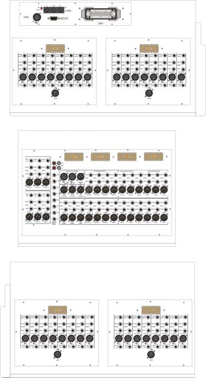
60 Rear Panel Configuration
61 1

62 Midas Legend Rear Panel (2 mono channel) 2
63
64 4 Edac Wiring Diagrams

65 Way Edac Connector Details = Individual Screens INPUTS 1 Mic In1 2 Mic In 2 Mic In 4 Mic In 4 Mic In Mic In 7 Mic In 7 8 Mic In 8 Direct Out 1 1 Direct Out 2 11 Direct Out Direct Out 4 1 Direct Out 14 Direct Out 1 Direct Out 7 1 Direct Out 8 This wiring pattern is the same for all input edacs. MIX & MASTERS Mix Out & Mix Bus Injects Master Out & Master Bus Injects 1 Mix 1 2 Mix Mix 2 4 Mix 1 Mix Mix 11 7 Mix 4 8 Mix Mix 1 Master L 11 Mix Master C 1 Mix 7 14 Master R 1 Mix 8 1 Chassis GROUP & SOLO Group Out & Group Bus Injects Solo Out & Solo Bus Injects 1 Group 1 2 FOH L Group 2 4 FOH C Group FOH R 7 Group 4 8 MON AFL Group 1 FOH PFL 11 Group MON PFL 1 Group 7 14 Chassis 1 Group 8 1 Chassis
66 Block Diagrams
67 7
68 MIC/LINE XLR INPUT B MIC/LINE JACK INPUT B EDAC MULIPIN SEND PHANTOM 48V INSERT POINT + - PAD gain + + PHASE REVERSE - O insert post only FOH INSERT FOH OR PRE EQ hi-pass VCA l stereo PAN c pan image r lcr LCR GROUP BUS SELECT ST MONO GROUP BUSSES 1-8 LEFT BUS RIGHT BUS MONO BUS RETURN front of house EQ SOLO LEFT SOLO BUS CENTER SOLO BUS RIGHT SOLO BUS PFL BUS 8 VCA BUSSES 1-1 MON - 2 bass SET VCA BUS SELECT VCA BUS SELECT MON - SET LEDS MAY FUNCTION IN ANY ONE OF FOUR WAYS AS SHOWN. FUNCTION IS DEPENDANT ON ASSIGN MASTER SWITCHES. lo-mid k 1 2k 1. 2 SET SUB GROUP MON SET MIX GROUP - hi-mid k k 4 8k 1. SET F.O.H. VCA GROUP + SET MON MONITOR VCA GROUP 2k f.o.h. CAN BUS - treble k 1k 2k hi-mid 2 monitor db lo-mid k 4k 1 4 1k 2k f.o.h. monitor monitor EQ DETECT VCA TO OTHER MIX SENDS PRE PRE / POST INTERNAL LINK SOLO SOLO SIGNAL PATH KEY = ANALOGUE SIGNALS = D.C. SIGNALS = AUTOMATION SIGNALS DIRECT OUTPUT EDAC MULTIPIN FOH 1 BUS MONITOR 1BUS AFL BUS PFL BUS LEGEND INPUT MODULE BLOCK DIAGRAM ISSUE 1 DATE
69 l c r ambience (solo level) LC 21 groups(st. return/matrix) masters(f.o.h.solo) LEGEND METERS MODULE BLOCK DIAGRAM ISSUE 1 DATE-2-2 GRP ST MTX meter select THESE METERS AUTOMATICALLY SWITCH BETWEEN LEFT / CENTER / RIGHT / AMBIENCE AND FOH SOLO LEFT / CENTER / RIGHT / MONO MONITOR SOLO IF A SOLO SWITCH IS PRESSED IF THE PFL SWITCH IN THE MONITOR SECTION IS SELECTED THE AUTOMATIC MONITOR FUNCTION BECOMES NOTHING / FOH PFL / NOTHING / MONITOR PFL
70 MIC REAR PANEL INPUT LEFT TAPE INPUT RIGHT TAPE INPUT PHANTOM _ + _ +1 + gain 1k k treble 4 8k 1k bass 1 2k stereo mono hi-mid lo-mid ST MONO AMBIENCE BUS LEFT BUS RIGHT BUS MONO BUS TAPE INPUT LEFT TAPE INPUT RIGHT LEGEND TALK MODULE BLOCK DIAGRAM ISSUE 1 DATE k k frequency OSC PINK PINK ON level + ST MONO GRP GRP MTX EXT dimmers littlite led LITTLITES LED BUS STEREO TALK MONO TALK GROUP 1-4 TALK GROUP -8 TALK MATRIX TALK TALK EXTERNAL REAR PANEL OUTPUT TALK BACK MIC INPUT TALK EXTERNAL REAR PANEL INPUT NEUTRIK 2 +48V mic ON rev tb level SOLO + SOLO SOLO MONITOR DIM LEFT SOLO BUS RIGHT SOLO BUS PFL BUS MONITOR PFL BUS MONITOR AFL BUS SOLO LOGIC BUS +1 +
71 - + AMBIENCE MIC FOH BUS MONITOR BUSS BUS INJECT (EDAC) + ambience MON 1 k 1k. 2 1k k 2k 2k 4 8k k k EQ +1dB - O SOLO MIX OUTPUT MIX OUTPUT (EDAC) 1 TALK BUSS SEND MIX INSERT POINT RETURN AUTOMATION CAN BUS TALK + - LEGEND MIX MODULE BLOCK DIAGRAM ISSUE 1 DATE SOLO MONITOR AFL BUS MONITOR PFL BUS FOH PFL BUS FOH LEFT SOLO BUS FOH RIGHT SOLO BUS
72 RETURN MASTER LEFT INSERT POINT SEND MASTER LEFT INJECT (EDAC) MASTER LEFT BUSS MASTER RIGHT BUSS MASTER RIGHT INJECT (EDAC) SEND MASTER RIGHT INSERT POINT RETURN LEGEND MASTERS MODULE BLOCK DIAGRAM ISSUE 1 DATE-2-2 l c balance r +1dB 1 +1dB MASTER LEFT MATRIX FEED MASTER LEFT MONITOR FEED MASTER LEFT OUTPUT EDAC MASTER RIGHT OUTPUT EDAC MASTER RIGHT MONITOR FEED MASTER RIGHT MATRIX FEED MASTER MONO MATRIX FEED MASTER MONO MONITOR FEED MASTER MONO BUSS MASTER MONO INJECT (EDAC) SEND MASTER RIGHT INSERT POINT dB 1 MASTER MONO OUTPUT EDAC RETURN
73 LEFT LINE INPUT RIGHT LINE INPUT stereo effects return k 1k 2k treble 2k k k 8k hi-mid lo-mid 1k bass 2 EQ +1dB +1dB l pan r PAN GROUP BUS SELECT MONO LEFT METER FEED RIGHT METER FEED GROUP BUSSES 1-8 MONO BUS ST LEFT BUS RIGHT BUS SIGNAL PATH KEY = ANALOGUE SIGNALS = AUTOMATION SIGNALS LEGEND STEREO EFFECTS RETURN BLOCK DIAGRAM ISSUE 1 DATE7-2-2 SEND INSERT POINT RETURN f.o.h SET SET LEDS ARE USED TO ASSIGN THE STEREO EFFECTS RETURN TO GROUPS DEPENDANT ON ASSIGN MASTER SWITCHES. CAN BUS +1 monitor +1dB SOLO SOLO SOLO LEFT SOLO BUS RIGHT SOLO BUS PFL BUS MONITOR PFL BUS MONITOR AFL BUS AUX BUS1 MIX BUS 1 AUX BUS 2 MIX BUS 2 AUX BUS MIX BUS AUX BUS 11 MIX BUS
74 - + RETURN GROUP LEFT INSERT POINT c SIS ST LEFT BUS SEND l r GROUP INJECT (EDAC) GROUP BUSS GROUP TALK BUSS AUTOMATION CAN BUS +1dB pan SOLO MONO SOLO RIGHT BUS MONO BUS LEFT SOLO BUS CENTER SOLO BUS RIGHT SOLO BUS PFL BUS MONITOR PFL BUS MONITOR AFL BUS GROUP OUTPUT LEGEND GROUP MODULE BLOCK DIAGRAM ISSUE 1 DATE-2-2 GROUP OUTPUT (EDAC) MATRIX BUS METER FEED
75 - + TALK 1 8 L R 1 8 l LEGEND MATRIX MODULE BLOCK DIAGRAM ISSUE 1 DATE-2-2 C r c dB MATRIX OUTPUT EXTERNAL INPUT AUTOMATION SEND + - ext + SOLO MTX meter select METER INSERT POINT RETURN LEFT SOLO BUS RIGHT SOLO BUS CENTRE SOLO BUS FOH PFL MONITOR PFL MONITOR AFL
76 FOH LEFT BUS OUTPUT (EDAC) - + FOH LEFT INJECT (EDAC) FOH LEFT BUSS FOH RIGHT BUS OUTPUT (EDAC) FOH RIGHT INJECT (EDAC) FOH RIGHT BUSS - + MONO FEED LEFT FEED RIGHT FEED MONO MONO ST -db LEGEND MONITOR MODULE BLOCK DIAGRAM ISSUE 1 DATE8-2-2 DIM INPUT FOH CENTER BUS OUTPUT (EDAC) FOH CENTER INJECT (EDAC) FOH CENTER BUSS MONITOR AFL BUS OUTPUT (EDAC) MONITOR AFL BUS INJECT (EDAC) MONITOR AFL BUS FOH PFL BUS OUTPUT (EDAC) db input f.o.h. MON MON TAPE INPUT LEFT TAPE INPUT RIGHT output stereo mono + stereo solo + mono solo TAPE +db +db +db -db -db VCA VCA VCA monitor +1 LOCAL LEFT OUTPUT LOCAL CENTER OUTPUT LOCAL RIGHT OUTPUT + FOH PFL INJECT (EDAC) FOH PFLBUSS MONITOR PFL BUS OUTPUT (EDAC) - + SOLO ACTIVE SOLO CLEAR SIS MODE PFL TO ST AFL TO ST MONITOR TO ST PFL TO MONO AFL TO MONO MONITOR TO MONO LOGIC CODE stereo SOLO solo PFL -db +1 phones headphones MONITOR PFL BUS INJECT (EDAC) SOLO ADD SIS ADD MONITOR PFL BUS mono SOLO CLEAR
77 7
78 8 Specification and Overview
79
80 LEGEND SPECIFICATION OVERVIEW AND STATISTICS. 1. The Legend is a 2 buss console with an additional x output matrix. The busses are as follows:- 8 audio groups = 8 mono aux = 1 stereo master = 2 1 mono master = 1 1 stereo AFL = 2 1 mono PFL = 1 1 mon AFL = 1 2 monitor solos = 2 TOTAL = 2 2. The Legend has 1 VCA sub groups which include VCA sub group muting.. The Legend XLR input count is a follows:- 4. The Legend has a total XLR output count of as follows:- 8 audio group outputs aux outputs matrix outputs master outputs local outputs 1 talk external output XLR Input count Frame Size (Mic Input Talk Mic Inputs Ambient Mic Input The Legend has a total of balanced ¼ inch jacks for inserts as follows:- Frame Size Balanced ¼ Jack Inserts Input channel insert sends Input channel insert returns Audio group insert sends Audio group insert returns Aux insert sends Aux insert returns Matrix insert sends Frame Size Balanced ¼ Jack Inserts Matrix insert returns Master insert sends Master insert returns Channel direct outputs Channel line inputs Stereo effects inputs Matrix external inputs The Legend has (48 frame) 2 (4 frame) 44 (2 frame) (24 frame) long throw faders for mix control and 72 (48 frame) 4 (4 frame) (2 frame) 48 (24 frame) short throw faders. 8. The Legend has a total of 72 (48 frame) 4 (4 frame) (2 frame) 48 (24 frame) peak program meters with 11 LED segments on all outputs and 7 LED segments on input channels. 7
81 LEGEND TECHNICAL SPECIFICATIONS. Input Impedance Mic 2k Balanced Line 2k Balanced Input Gain Mic Continuously variable from (all faders at db) + 1dB to + db Mic + Pad Line Level Inputs Continuously variable from - 1dB to + db db Maximum Input Level Mic + dbu Mic + Pad + 1dBu Line Level Inputs + 21dBu CMR at 1kHz Mic (gain + 4dB) > 8dB Mic + Pad (gain db) > db Frequency Response Mic to Mix (2 to 2kHz) (gain + 4dB) + db to - 1dB Noise (2 to 2kHz) Mic EIN ref. 1 (gain + db) - 8dBu System Noise (2 to 2kHz) Summing Noise (48 channels routed with faders down) Line to Mix Noise (48 channels routed at db, pan centre) - 8dB - 7dB Distortion at 1kHz Mic to Mix (+ 4dB gain, dbu output) <.% Crosstalk at 1kHz Channel to Mix < - 8dB Maximum Fader attenuation > 7dB Output Impedance All Line Outputs Ohms Balanced Source to drive > Headphones To drive > 8 Maximum Output Level All Line Outputs + 21dBu Headphones + 21dBu 71
82 Nominal Signal Level Mic - dbu to + 1dBu Line dbu Headphones + 1dBu Equaliser FOH & MON input Hi pass Slope db / Oct Hi pass Frequency Continuously variable - db point from 2Hz to 4Hz FOH input & MON output MON input Treble Gain Treble Shelving Freq. Hi Mid Gain Hi Mid Freq. Hi Mid Bandwidth Lo Mid Gain Lo Mid Freq. Lo Mid Bandwidth Bass Gain Bass Shelving Freq. Hi Mid Gain Hi Mid Freq. Lo Mid Gain Lo Mid Freq. Continuously variable + 1 db to - 1 db Centre detent = db Continuously variable - db point from 2KHz to 2KHz Continuously variable + 1 db to - 1 db Centre detent = db Continuously variable Centre from 4Hz to 8KHz Continuously variable.1 Oct. to 2 Oct Centre detent =.4 Oct Continuously variable + 1 db to - 1 db Centre detent = db Continuously variable Centre from 1Hz to 2KHz Continuously variable.1 Oct. to 2 Oct Centre detent =.4 Oct Continuously variable + 1 db to - 1 db Centre detent = db Continuously variable - db point from 2Hz to 4Hz Continuously variable + 1 db to - 1 db Centre detent = db Continuously variable Centre from 4Hz to 1KHz Continuously variable + 1 db to - 1 db Centre detent = db Continuously variable Centre from Hz to 2Khz 72
83 7
84 74 MIDAS L7 Power Supply

85 Power on / off switches Front View The POWER indicators show the status of all rails on the power supplies. IEC sockets Fuses DC power connector SUPPLY VOLTAGE 1-24V~ -Hz 7W FUSE T.A 2V psu 1 MADE IN KIDDERMINSTER ENGLAND SUPPLY VOLTAGE 1-24V~ -Hz 7W FUSE T.A 2V psu 2 C US Rear View Measurements and Specifications 7.2mm 88.mm.48 4.mm. 482.mm 1 Dimensions and Weights Width: Height 2U: Depth: Depth (incl. connectors) 482.mm mm mm 14. : 4.mm 1. Specifications Input Voltage Range: Maximum Output Power: Operating Temperature: 1-24VAC 7W - o C Weight: 1.Kg 28.lbs 7

86 Input Crib Sheet Inputs to Notes: 7 Input No
arthur ART48 - YELLOW ACOUSTIC FIDELITY USER MANUAL Assembling instruction on ART48-L/Rmast manual
 V2 ACOUSTIC FIDELITY arthur ART48 - YELLOW USER MANUAL Assembling instruction on ART48-L/Rmast manual WARNINGS PRECAUTIONS WARNINGS Read carefully this manual and follow these precautions before operating
ECA COMMERCIAL AMPLIFIER OWNER S MANUAL ECA-70MIXAMP V / 70V / 4Ω Amplifier ECA-70MIXAMP-1-60 OUTPUT LEVEL POWER MASTER MIC 1
 OWNER S MANUAL ECA COMMERCIAL AMPLIFIER ECA-MIXAMP--6 V / V / Ω Amplifier TEMP PROT OUTPUT LEVEL ECA-MIXAMP--6 6 POWER MIC MIC MIC MIC AUX AUX BASS TREBLE 5 5 5 5 5 6 6 6 6 6 MASTER 5 6 ON OFF + - + -
plifier D-501 otion Am Tactile M
 Tactile Motion Amplifier D-501 IMPORTANT SAFETY INSTRUCTIONS WARNING: 1. Read and keep these instructions for future reference. 2. Do not use this apparatus near water. 3. Clean only with a dry cloth.
M-300 Mono power amplifier User s guide
 M-300 Mono power amplifier User s guide M-300 Mono power amplifier User s guide Specifications: Contents: Power output: 8Ω: 290W, 0.01% THD SPECIFICATIONS Page 2 Input impedance: Gain: 4Ω: 580W, 0.01%
Model CC4041. CC Series Amplifier. Installation and Use Manual
 BASS 0 TREBLE 0-12 +12-12 +12 INPUT 1 INPUT 2 INPUT 3 INPUT 4 PEAK SIGNAL POWER POWER CC Series Amplifier Model CC4041 Installation and Use Manual 2012 Bogen Communications, Inc. All rights reserved. Specifications
HARMONY SINGER 2. Battery-Powered Vocal Effects Stompbox with Guitar-Controlled Harmony, Reverb and Tone. User Manual
 HARMONY SINGER 2 Battery-Powered Vocal Effects Stompbox with Guitar-Controlled Harmony, Reverb and Tone User Manual 2 Harmony Singer 2 User Manual Important Safety Instructions Terminals marked with this
CABINET POWERED MIXING CONSOLE
 R SHS AUDIO SPMU- 00 CABINET POWERED MIXING CONSOLE USER'S MANUAL SAFETY INSTRUCTIONS SPECIFICATIONS Inputs Input modes Input Impedance Rated Input level Connector WARNING - TO REDUCE THE RISK OF FIRE
Model CC4052. CC Series Amplifier. Installation and Use Manual
 CC Series Amplifier Model CC4052 Installation and Use Manual 2012 Bogen Communications, Inc. All rights reserved. Specifications subject to change without notice. 54-2216-01A 1303 NOTICE: Every effort
Classic Series Public Address Amplifiers C10 & C20 Models
 Classic Series Public Address Amplifiers C10 & C20 Models Installation and Use Manual 2009 Bogen Communications, Inc. All rights reserved. Specifications subject to change without notice. 54-5978-01B 0901
MIC MECHANIC 2. Ultra-Simple Battery-Powered Vocal Effects Stompbox with Echo, Reverb and Pitch Correction. User Manual
 MIC MECHANIC 2 Ultra-Simple Battery-Powered Vocal Effects Stompbox with Echo, Reverb and Pitch Correction User Manual 2 MIC MECHANIC 2 User Manual Important Safety Instructions Terminals marked with this
T L Audio. User Manual EQ1 VALVE EQUALISER. Tony Larking Professional Sales Limited, Letchworth, England.
 T L Audio User Manual EQ1 VALVE EQUALISER Tony Larking Professional Sales Limited, Letchworth, England. Tel: 01462 490600, International +44 1462 490600. Fax: 01462 490700, International +44 1462 490700.
KLASIK NEAR FIELD ACTIVE STUDIO MONITOR
 USER S MANUAL KLASIK NEAR FIELD ACTIVE STUDIO MONITOR CONTENTS page INTRODUCTION GENERAL INFORMATION 3 REAR PANEL REAR PANEL 4 INPUTS 5 SWITCHES 5 TECHNICAL SPECIFICATIONS TECHNICAL SPECIFICATIONS 7 SAFETY
Classic Series Amplifiers C35, C60, & C100 Models
 Classic Series Amplifiers C35, C60, & C100 Models Installation and Use Manual 2009 Bogen Communications, Inc. All rights reserved. Specifications subject to change without notice. 54-5979-02E 1203 Notice:
Lanen True Diversity UHF Systems For electric and bass guitars: GB21 For Series 21 mics: UHF21. User Manual GB21 receiver/uhf21 transmitter
 Lanen True Diversity UHF Systems For electric and bass guitars: GB21 For Series 21 mics: UHF21 User Manual GB21 receiver/uhf21 transmitter Safety Information Thank you for purchasing this digital appliance.
User Manual LMS-325 Line Monitor Speaker
 User Manual LMS-325 Line Monitor Speaker 9350-7490-000 Rev E 10/2010 PROPRIETARY NOTICE The product information and design disclosed herein were originated by and are the property of Bosch Security Systems,
MIXING CONSOLE CX-124 CX-164. TOA Corporation. Operating Instructions
 MIXING CONSOLE Operating Instructions CX-124 CX-164 Please follow the instructions in this manual to obtain the optimum results from these units. We also recommend you to keep this manual handy for future
Big Bang. B B O w n e r s M a n u a l. Power Amplifiers. SpeakerCraft BB2125 POWER ACTIVE PROTECTION L
 Big Bang Power Amplifiers SpeakerCraft BB2125 ACTIVE POWER PROTECTION L R B B 2 1 2 5 O w n e r s M a n u a l SAFETY INSTRUCTIONS APPLICABLE FOR USA, CANADA OR WHERE APPROVED FOR USAGE CAUTION: To reduce
Spider. Pilot s Handbook Manuel de pilotage Pilotenhandbuch Pilotenhandboek Manual del Piloto 取扱説明書
 Spider IV Pilot s Handbook Manuel de pilotage Pilotenhandbuch Pilotenhandboek Manual del Piloto 取扱説明書 Get free lessons and tones! Join Spider Online! www.line6.com/spideronline 40-00-0186 Pilot s Handbook
A Channel Amplifier
 Installation Manual A2150 2 Channel Amplifier Table of Contents Installation Requirements and Recommendations 1 What s included 1 Speaker Wire Recommendations 1 Setup 2 Rack Mounting 2 Individually Protected
SVS SoundPath Wireless Audio Adapter Owner s Manual
 SVS SoundPath Wireless Audio Adapter Owner s Manual SVS SoundPath Wireless Audio Adapter Thank you for choosing SVS! The SoundPath Wireless Audio Adapter reduces subwoofer cable clutter without sacrificing
Safety Precautions. Important Safety Instructions
 Thank you for purchasing this digital piano. For optimal operation and security, please read this manual carefully and keep it for future reference. Safety Precautions The lightning flash with arrowhead
Classic Series Public Address Amplifiers C10 & C20 Models
 Classic Series Public Address Amplifiers C10 & C20 Models Installation and Use Manual 2009 Bogen Communications, Inc. All rights reserved. Specifications subject to change without notice. 54-5978-01C 1106
IMPORTANT SAFETY INSTRUCTIONS
 IMPORTANT SAFETY INSTRUCTIONS The apparatus shall not be exposed to dripping or splashing and that no objects with liquids, such as vases, shall be placed on the apparatus. The MAINS plug is used as the
USER MANUAL APG DYNAMIC PROCESSORS MATRIX ARRAY SYSTEMS 4000SP 6000SP 9000SP
 USER MANUAL APG DYNAMIC PROCESSORS MATRIX ARRAY SYSTEMS 4000SP 6000SP 9000SP SAFETY INSTRUCTIONS This symbol, wherever it appears, alerts you to the presence of uninsulated dangerous voltage inside the
A WORLD OF LISTENING WARNING: TO PREVENT FIRE OR ELECTRIC SHOCK HAZARD, DO NOT EXPOSE THIS PRODUCT TO RAIN OR MOISTURE.
 DDR-3 FM RDS/DAB digital radio A WORLD OF LISTENING THE LIGHTNING FLASH AND ARROW- HEAD WITHIN THE TRIANGLE IS A WARNING SIGN ALERTING YOU OF DANGEROUS VOLTAGE INSIDE THE RADIO. WARNING: TO PREVENT FIRE
British Audio Engineering
 British Audio Engineering 1073 INSTRUCTION MANUAL 7421 Laurel Canyon Blvd, Unit 14 N. Hollywood CA 91605 (818) 784-2046 baeaudio.com i Table of Contents Safety Instructions... 1 Warranty... 2 Specifications...
MIXER POWER AMPLIFIER BG-130
 OPERATING INSTRUCTIONS MIXER POWER AMPLIFIER BG-115 BG-130 TO REDUCE THE RISK OF ELECTRICAL SHOCK, DO NOT REMOVE COVER. NO USER SERVICEABLE PARTS INSIDE. REFER SERVICING TO QUALIFIED SERVICE PERSONNEL
DPA-1.2. Instruction Manual. 2 Channel Amplifier with Auto A/B Selector DPA-1.2 DPA-1.2 POWER SERIAL # LINE INPUT SENSING SPEAKER B OUT
 POWER Russound DPA-1.2 Instruction Manual 2 Channel Amplifier with Auto A/B Selector NEWMARKET, NH USA DPA-1.2 Russound 68835 Conforms to UL 6500 Certified to CSA C22.2 No1-94 DPA-1.2 Tested to Comply
PREZONE1 Instruction manual
 PREZONE1 Instruction manual PREZONE1 manual PREZONE1 Instruction manual 3 4 Preamplifiers IMPORTANT SAFETY INSTRUCTIONS Read these instructions - All the safety and operating instructions should be read
DA216S DISTRIBUTION AMPLIFIER
 DISTRIBUTION AMPLIFIER IMPORTANT SAFETY INSTRUCTIONS 1. Read these instructions. 2. Keep these instructions. 3. Heed all warnings. 4. Follow all instructions. 5. Do not use this apparatus near water. 6.
REVAMP4100 Instruction manual
 REVAMP4100 Instruction manual REVAMP4100 Instruction manual 3 REVAMP4100 manual 4 CLASS-D POWER AMPLIFIER IMPORTANT SAFETY INSTRUCTIONS 1. Read these instructions 2. Keep these instructions 3. Heed all
WX-1 & WX-3 OPERATING MANUAL AND USER GUIDE. Professional Power Amplifier. WX-1 and WX-3.indd :23:16
 WX-1 & WX-3 Professional Power Amplifier OPERATING MANUAL AND USER GUIDE 3 www.wharfedalepro.com WX-1 and WX-3.indd 1 2014-7-16 10:23:16 TABLE OF CONTENTS TABLE OF CONTENTS... 1 IMPORTANT WARNINGS & SAFETY
Spider Valve. Pilot s Guide Manuel de pilotage Pilotenhandbuch Pilotenhandboek Manual del Piloto 取扱説明書
 Spider Valve MKII Pilot s Guide Manuel de pilotage Pilotenhandbuch Pilotenhandboek Manual del Piloto 取扱説明書 40-00-0233 Pilot s Handbook available @ www.line6.com/manuals Rev D Important Safety Instructions
JAM combo amplifier for acoustic instruments
 JAM combo amplifier for acoustic instruments IMPORTANT SAFETY INSTRUCTIONS THE LIGHTNING FLASH WITH ARROWHEAD SYMBOL, WITHIN AN EQUILATERAL TRIANGLE, IS INTENDED TO ALERT THE USER TO THE PRESENCE OF UNINSULATED
10 WATT GUITAR COMBO
 10 WATT GUITAR COMBO Caution: To reduce the hazard of electrical shock, do not remove cover or back. No user serviceable parts inside. Please refer all servicing to qualified personnel. WARNING: To reduce
T L Audio INDIGO SERIES. User Manual VP-2051 VALVE VOICE PROCESSOR. Tony Larking Professional Sales Limited, Letchworth, England.
 T L Audio INDIGO SERIES User Manual VP-2051 VALVE VOICE PROCESSOR Tony Larking Professional Sales Limited, Letchworth, England. Tel: 01462 490600. International +44 1462 490600. Fax: 01462 490700. International
REVAMP4120T Instruction manual
 REVAMP4120T Instruction manual REVAMP4120T Instruction manual 3 REVAMP4120T manual 4 CLASS-D POWER AMPLIFIER IMPORTANT SAFETY INSTRUCTIONS 1. Read these instructions 2. Keep these instructions 3. Pay
Spider IV 15. Pilot s Handbook Manuel de pilotage Pilotenhandbuch Pilotenhandboek Manual del Piloto 取扱説明書
 Spider IV 15 Pilot s Handbook Manuel de pilotage Pilotenhandbuch Pilotenhandboek Manual del Piloto 取扱説明書 Get free lessons and tones! Join Spider Online! www.line6.com/spideronline 40-00-0187 Pilot s Handbook
T L Audio CRIMSON SERIES. User Manual EQ-3012 PARAMETRIC EQUALISER. Tony Larking Professional Sales Limited, Letchworth, England.
 T L Audio CRIMSON SERIES User Manual EQ-3012 PARAMETRIC EQUALISER Tony Larking Professional Sales Limited, Letchworth, England. Tel: 01462 490600. International +44 1462 490600. Fax: 01462 490700. International
A32. f u l l y b a l a n c e d p o w e r a m p l i f i e r. user guide
 A32 f u l l y b a l a n c e d p o w e r a m p l i f i e r user guide Welcome! Welcome to the Primare A32 Amplifier! The A32 is a modular power amplifier designed as the ideal output stage in a home theatre
T L Audio CRIMSON SERIES. User Manual EQ-3011 EQUALISER. Tony Larking Professional Sales Limited, Letchworth, England.
 T L Audio CRIMSON SERIES User Manual EQ-3011 EQUALISER Tony Larking Professional Sales Limited, Letchworth, England. Tel: 01462 490600. International +44 1462 490600. Fax: 01462 490700. International +44
PP-9213 Pre Amplifier
 PP-923 Pre Amplifier CH CH2 CH3 CH4 CH5 CH6 CH7 CH8 CH9 INPUTS MASTER OUTPUTS PEAK -6-6 -6-6 AUX AUX2 - POWER ON PRIORITY - 6 SUB OFF PRIORITY2 SUB2 6 MASTER * Rack mount products in the Western Hemisphere(North
CSP & CSL-SERIES MIXING CONSOLES. Item ref: UK, UK, UK, UK, UK, UK User Manual. Version 2.
 CSP & CSL-SERIES MIXING CONSOLES Item ref: 170.841UK, 170.843UK, 170.845UK, 170.851UK, 170.853UK, 170.855UK User Manual Version 2.0 Caution: Please read this manual carefully before operating Damage caused
Instruction Manual Please read carefully before use and keep for future reference.
 Easy-Read Dual Alarm Clock with Daily Repeat, Bluetooth, and USB Charge Port NRC-181 Instruction Manual Please read carefully before use and keep for future reference. Important Safety Information CAUTION
ENGLISH TERROR BASS 500/1000
 1 THANK YOU! Thank you for choosing Orange. You are now a member of the Legendary British Guitar Amplifier owners club! Since 1968 when the company was founded, Orange has been a pioneering force in the
IMPORTANT SAFETY INSTRUCTIONS
 WR-2 GB Version 1 IMPORTANT SAFETY INSTRUCTIONS 1. 2. 3. 4. 5. 6. 7. 8. 9. Read these instructions. Keep these instructions. Heed all warnings. Follow all instructions. Do not use this apparatus near water.
DSR-3. Bedienungsanleitung User Guide
 DSR-3 Bedienungsanleitung User Guide EN Introduction The invention of the Hammond organ in the last century's mid 30s resulted in a need for artificial reverb. This led to the development of spring reverberation
STEREO POWER AMPLIFIER OWNER MANUAL PR-150 DESIGNED IN U.K. PDF created with FinePrint pdffactory trial version
 STEREO POWER AMPLIFIER OWNER MANUAL PR-150 DESIGNED IN U.K. INTRODUCTION Congratulations on your purchase of MA PR-150 Stereo Power Amplifier. The performance of PR-150 is perfect for any audio application,
a u d i o p h i l e d i g i t a l - t o - a n a l o g u e c o n v e r t e r user guide
 DAC30 a u d i o p h i l e d i g i t a l - t o - a n a l o g u e c o n v e r t e r user guide Welcome! Welcome to the Primare DAC30! Your DAC30 is a fully balanced audiophile digitalto-analogue converter,
REVAMP2250 Instruction manual
 REVAMP2250 Instruction manual REVAMP2250 Instruction manual 3 REVAMP2250 Manual 4 CLASS-D POWER AMPLIFIER IMPORTANT SAFETY INSTRUCTIONS 1. Read these instructions 2. Keep these instructions 3. Heed all
Dual Alarm Clock Radio with Digital Tuning NRC-174. Instruction Manual Please read carefully before use and keep for future reference.
 Dual Alarm Clock Radio with Digital Tuning NRC-174 Instruction Manual Please read carefully before use and keep for future reference. Important Safety Information CAUTION RISK OF ELECTRIC SHOCK DO NOT
INSTALLATION MANUAL ECA-70VMINI-60W ECA-70VMINI-60W L VOLUME SPEAKER OUTPUTS 12VDC IN + L+ L- GND R+ R- S GND GND Tx Rx
 INSTALLATION MANUAL ECA-70VMINI-60W ECA-70VMINI-60W L VOLUME R 12VDC IN BALANCED IN STEREO IN UNBALANCED IN SERVICE STATUS IR RS-232 + L+ L- GND R+ R- S GND GND Tx Rx SPEAKER OUTPUTS + page 2 CAUTION Risk
HTA125A/250A. Power Amplifiers. Installation & Use Manual
 HTA125A/250A Power Amplifiers Installation & Use Manual Specifications subject to change without notice. 2010 Bogen Communications, Inc. All rights reserved. 54-5832-04B 1011 NOTICE: Every effort was made
POWERED MIXER DIGITAL ECHO EFFECT ECHO LEVEL ECHO LEVEL ECHO LEVEL ECHO LEVEL ECHO VOL REPEAT MPM CHANNEL POWERED MIXER OWNER S MANUAL
 POWERED MIXER DIGITAL ECHO EFFECT ECHO LEVEL ECHO LEVEL ECHO LEVEL ECHO LEVEL ECHO VOL REPEAT MPM 480 4-CHANNEL POWERED MIXER OWNER S MANUAL MPM 480 4-CHANNEL POWERED MIXER Congratulations! You have just
R-Series R235LS 2-Channel Power Amplifier with Local Source Switching
 R-Series R235LS 2-Channel Power Amplifier with Local Source Switching User s Manual On Off R235LS POWER A MPLIFIER IMPORTANT SAFEGUARDS WARNING TO REDUCE THE RISK OF FIRE OR ELECTRIC SHOCK, DO NOT EXPOSE
Primare A33.2 Amplifier User Guide
 > Primare A33.2 Amplifier User Guide > Preface CAUTION RISK OF ELECTRIC SHOCK DO NOT OPEN CAUTION: To reduce the risk of electrical shock do not remove cover (or back). No user serviceable parts inside.
UA ª 35T II Utility Amplifier OPERATING INSTRUCTIONS
 OPERATING INSTRUCTIONS Intended to alert the user to the presence of uninsulated "dangerous voltage" within the product's enclosure that may be of sufficient magnitude to constitute a risk of electric
3400 Watt Stereo Power Amplifier
 3400 Watt Stereo Power Amplifier OWNER'S MANUAL Copyright 2014, Samson Technologies Corp. v1.1 Samson Technologies Corp. 45 Gilpin Ave Hauppauge, NY 11788 www.samsontech.com Important Safety Information
ZM-6. Professional 19 Rack Mixer USER MANUAL. Content
 Professional 19 Rack Mixer ZM-6 USER MANUAL Thank you for buying an LD Systems audio product. Please read these operating instructions carefully before you use the product for the first time and keep them
IMPORTANT SAFETY INSTRUCTIONS
 WR-1 Version 1 IMPORTANT SAFETY INSTRUCTIONS 1. 2. 3. 4. 5. 6. 7. 8. 9. Read these instructions. Keep these instructions. Heed all warnings. Follow all instructions. Do not use this apparatus near water.
MAZ 18/MAZ 38. Manual. Model: ZA-8 / ZA-5.
 MAZ 18/MAZ 38 Manual Model: ZA-8 / ZA-5 www.drzamps.com This symbol warns the user of dangerous voltage levels localized within the enclosure. This symbol advises the user to read all accompanying literature
User Manual. MA 21 Two zone mixing amplifier
 User Manual MA 21 Two zone mixing amplifier Safety instructions When using this electronic device, basic precautions should always be taken, including the following: 1 Read all instructions before using
THE NEW FACE OF BASS PRO BASS SYSTEM U30, U60, U120. Owner s Manual
 152420M-1 07/18 THE NEW FACE OF BASS Blackstar Amplification Ltd, Beckett House, 14 Billing Road, Northampton, NN1 5AW, UK For the latest information go to: www.blackstaramps.com PRO BASS SYSTEM U30, U60,
SR Series Crossovers. Owner s Manual SR 823 SR 834. A Harman International Company
 SR Series Crossovers Owner s Manual SR 823 SR 834 A Harman International Company Warning For your protection, please read the following: These symbols are internationally accepted symbols that warn of
Comfort Digisystem User Manual. SecureStream Technology. Receiver DH10. English
 Comfort Digisystem User Manual SecureStream Technology Receiver DH10 English User manual Table of contents Page Introduction to the Comfort Digisystem 3 Functions of the Receiver DH10 4 Getting started
A-16D A-Net Distributor
 A-16D A-Net Distributor For use with the Personal Monitor Mixing System Information in this document is subject to change. All rights reserved. Copyright 2003 Aviom, Inc. Printed in USA Document Rev. 1.03
USER MANUAL APG DYNAMIC PROCESSORS LPMC216 - LPDS8 - LPDS12S - LDSP15 - LPDS15S - LPMX4 - LP3000C - LPSC25
 USER MANUAL APG DYNAMIC PROCESSORS LPMC216 - LPDS8 - LPDS12S - LDSP15 - LPDS15S - LPMX4 - LP3000C - LPSC25 This symbol alerts you to the presence of un-insulated dangerous voltage inside the enclosure
Lanen Series 21 from Prodipe SB21 Lanen Instrument Mic. User Manual SB21 Lanen Sax / Brass / Percussion
 Lanen Series 21 from Prodipe SB21 Lanen Instrument Mic User Manual SB21 Lanen Sax / Brass / Percussion Safety Information Thank you for purchasing this digital appliance. To ensure perfect operation and
a u d i o p h i l e p r e a m p l i f i e r user guide
 PRE32 a u d i o p h i l e p r e a m p l i f i e r user guide Welcome! Welcome to the Primare PRE32! Your PRE32 is a high-quality audiophile preamplifier, designed as the ideal centrepiece of a home hi-fi
WM-SYS3/WM-SYS3D/WM-SYS4/WM-SYS4D
 WM-SYS3/WM-SYS3D/WM-SYS4/WM-SYS4D Wireless Kit For Active Speakers WIRELESS TRANSMITTER WM60 SIG/CLIP ON OFF ENGLISH User s Manual IMPORTANT SAFETY INSTRUCTIONS The apparatus shall not be exposed to dripping
H A 6 6 CHANNEL STEREO HEADPHONE AMPLIFIER INSTALLATION AND OPERATION MANUAL
 H A6 6 CHANNEL STEREO HEADPHONE AMPLIFIER INSTALLATION AND OPERATION MANUAL IMPORTANT SAFETY INFORMATION 1. Save the carton and packing material even if the equipment has arrived in good condition. Should
ZM 84 Audio Mixer. User Manual. Order code: CRAM41. Audio Mixer ZM 84 AUX 3 AUX 1 AUX 2 AUX 4 MASTER 1 MASTER 2 OFF BASS BASS TREBLE TREBLE BASS BASS
 ZM 84 Audio Mixer User Manual -20-10 0 +10 +20-20 -10 0 +10 +20 POWER L R 0 0 ON ZM 84 Audio Mixer AUX 4 MIC/LINE 1 MIC/LINE 1 MIC/LINE 2 MIC/LINE 3 MIC/LINE 4 THR THR +6 +10 +6 AUX 3 AUX 1 AUX 2 AUX 4
2BSST POWER AMPLIFIER OWNER S MANUAL
 2BSST POWER AMPLIFIER OWNER S MANUAL IMPORTANT SAFETY INSTRUCTIONS The lightning flash with arrowhead symbol within an equilateral triangle, is intended to alert the user to the presence of un-insulated
3.Avoid spilling liquids or allowing materials to enter the cabinet
 PUBLIC ADDRESS MIXER POWER AMPLIFIER INSTRUCTION MANUAL PL-260A 260 WATT RMS RISK OF ELECTRIC SHOCK, DO NOT OPEN! CAUTION: TO REDUCE THE RISK OF ELECTRIC SHOCK, DO NOT OPEN COVER. NO USER SERVICEABLE PARTS
mix 502, mix 802, mix 1202FX mixer user manual
 mix 502, mix 802, mix 1202FX mixer user manual Musikhaus Thomann Thomann GmbH Hans-Thomann-Straße 1 96138 Burgebrach Germany Telephone: +49 (0) 9546 9223-0 E-mail: info@thomann.de Internet: www.thomann.de
IMPORTANT SAFETY INSTRUCTIONS
 WR-11 Version 1 IMPORTANT SAFETY INSTRUCTIONS 1. Read these instructions. 2. Keep these instructions. 3. Heed all warnings. 4. Follow all instructions. 5. Do not use this apparatus near water. 6. Clean
User Manual. MA 240 Mixing amplifier
 User Manual MA 240 Mixing amplifier Safety instructions When using this electronic device, basic precautions should always be taken, including the following: 1 Read all instructions before using the product.
PROLUDE AMPLIFICATION D750. User s manual for the tube preamplifier version
 PROLUDE AMPLIFICATION D750 User s manual for the tube preamplifier version 1 2 Table of contents 1 INTRODUCTION...1 4 1.1 SOME WORDS TO THE CUSTOMER...1 4 1.2 SOME WORDS ABOUT ME...1 4 2 SAFETY INSTRUCTIONS,
Important safety instructions
 MMR-88 Version 1 Important safety instructions 1. 2. 3. 4. 5. 6. 7. 8. 9. Please read these instructions carefully. Please keep these instructions for future reference. Heed all warnings Follow all instructions
MC450/MC650 (MC750) OPERATING INSTRUCTIONS
 OPERATING INSTRUCTIONS") MC450/MC650 (MC750) OPERATING INSTRUCTIONS MC 2 AUDIO Ltd., Units 6 & 7 Kingsgate, Heathpark Industrial Estate, HONITON, Devon EX14 1YG England Tel: ++(0)1404.44633 Fax: ++(0)1404.44660 www.mc2-audio.co.uk
MC450/MC650 (MC750) OPERATING INSTRUCTIONS MC 2 AUDIO Ltd., Units 6 & 7 Kingsgate, Heathpark Industrial Estate, HONITON, Devon EX14 1YG England Tel: ++(0)1404.44633 Fax: ++(0)1404.44660 www.mc2-audio.co.uk
!!! WARNING!!! TO REDUCE THE RISK OF FIRE OR ELECTRIC SHOCK, DO NOT EXPOSE THIS UNIT TO RAIN OR MOISTURE.
 SAFETY PRECAUTIONS!!! WARNING!!! TO REDUCE THE RISK OF FIRE OR ELECTRIC SHOCK, DO NOT EXPOSE THIS UNIT TO RAIN OR MOISTURE. Avoid exposing rain, water, or any form of liquid to this unit. IMMEDIATELY unplug
EX WATT POWERED SUBWOOFER OWNERS MANUAL SAMSON
 WATT ED SUBWOOFER OWNERS MANUAL Caution: To reduce the hazard of electrical shock, do not remove cover or back. No user serviceable parts inside. Please refer all servicing to qualified personnel. Safety
AV30MX-2 Operation Manual
 AV30MX-2 Operation Manual 1 Important safety instructions 1. Please read carefully prior to product installation or operation. 2. Read these instructions. 3. Keep these instructions. 4. Heed all warnings.
XD-V30 Digital Wireless System
 XD-V30 Digital Wireless System Pilot s Handbook Manuel de pilotage Pilotenhandbuch Pilotenhandboek Manual del Piloto 取扱説明書 See www.line6.com/manuals for Advance Guide 40-00-0286 Advanced Users Guide available
Warning: Electrical Hazard... 3 Safety Instruction Sheet for STG Product Overview What s in the box?... 4
 STG-2412 User Guide Warning: Electrical Hazard... 3 Safety Instruction Sheet for STG-2412... 3 Product Overview... 4 What s in the box?... 4 Using STG-2412 for Mixing, Processing, and Recording... 5 Software
OWNER S MANUAL CPS 1 / CPS 2 CONTRACTOR PRECISION SERIES
 OWNER S MANUAL CPS 1 / CPS 2 CONTRACTOR PRECISION SERIES CONTENTS Introduction................................................................... 9 Front Panel...................................................................
ENGLISH THANK YOU! DARK TERROR. Thank you for choosing Orange. You are now a member of the Legendary British Guitar Amplifier owners club!
 ENGLISH THANK YOU! Thank you for choosing Orange. You are now a member of the Legendary British Guitar Amplifier owners club! Since 1968 when the company was founded, Orange has been a pioneering force
MLM82S MIC / LINE MIXER
 MLMS MIC / LINE MIXER IMPORTNT SFETY INSTRUCTIONS. Read these instructions.. Keep these instructions. 3. Heed all warnings.. Follow all instructions. 5. Do not use this apparatus near water.. Clean only
Mytek Studio Clock 192CX User Manual. Studio Clock 192CX. User Manual. ver. 1.0 / Jun 2011
 Studio Clock 192CX User Manual ver. 1.0 / Jun 2011 Mytek Digital 2011 Page: 1 / 9 This manual may be updated Download the newest version at: http:///download_library/ For technical support, technical tips
User Guide. Wideband 4-channel Auto Gain-Control Antenna Divider
 User Guide AD-708 Wideband 4-channel Auto Gain-Control Antenna Divider All rights reserved. Do not copy or forward without prior approvals MIPRO. Specifications and design subject to change without notice.
FOR AVLEX ONLY MT-24A. User Guide. 2.4 GHz Digital Stationary Transmitter
 2.4 GHz Digital Stationary Transmitter User Guide All rights reserved. MN 017/05 Do not copy or forward without prior approvals MIPRO. Specifications and design subject to change without notice. 2 CE5
N06... >> Manual. Puma 300, 500, 900
 N06... >> Manual Puma 300, 500, 900 >> Puma Tops Important Safety Instructions The apparatus shall not be exposed to dripping or splashing and that no objects with liquids, such as vases, shall be placed
Slim Audio Interface 4-Wire Quick Start Guide
 Slim Audio Interface 4-Wire Quick Start Guide Slim Audio Interface 4-Wire Quick Start Guide The Green-GO Slim Audio Interface 4-Wire can act as a general purpose line in/out device for purposes such as
V50D ELECTRIC GUITAR AMPLIFIER WITH DIGITAL DELAY AND CHORUS. User s Manual
 V50D ELECTRIC GUITAR AMPLIFIER WITH DIGITAL DELAY AND CHORUS User s Manual R Velocity is a registered trademark of GHS Corporation Battle Creek MI, USA May be covered by one or more of the following: U.S.
Dual Terror Owners Manual
 Dual Terror Owners Manual Orange Amplifiers OMEC House 108 Ripon Way Borehamwood Hertfordshire WD6 2JA ENGLAND Tel: +44 20 8905 2828 Fax: +44 20 8905 2868 info@omec.com Orange USA 2065 Peachtree Industrial
ENGLISH MICRO TERROR
 1 THANK YOU! Thank you for choosing Orange. You are now a member of the Legendary British Guitar Amplifier owners club! Since 1968 when the company was founded, Orange has been a pioneering force in the
LIVE 16 ORDERCODE D2211
 LIVE 16 ORDERCODE D2211 Congratulations! You have bought a great, innovative product from DAP Audio. The DAP Audio LIVE 16 brings excitement to any venue. Whether you want simple plug-&-play action or
PREMIUMAUDIOVIDEOLIGHTINGANDPOWERPRODUCTS
 FACTOR ELECTRONICS PREMIUMAUDIOVIDEOLIGHTINGANDPOWERPRODUCTS VT-1 / VT-4 Professional Tuners With RBDS Owners Manual Owners Manual IMPORTANT NOTE: THIS OWNER'S MANUAL IS PROVIDED AS AN INSTALLATION AND
RDX Quick Start Guide
 RDX Quick Start Guide Green-GO RDX Quick Start Guide Product description With the Green-GO Radio Interface you can connect your radio to the Green-GO network through a D-SUB 9 connector. Features Connect
LA-SERIES LOOP AMPLIFIERS. Item ref: UK, UK User Manual
 LA-SERIES LOOP AMPLIFIERS Item ref: 952.864UK, 952.867UK User Manual Caution: Please read this manual carefully before operating Damage caused by misuse is not covered by the warranty SAFETY SYMBOL AND