AIW26B. Operating Manual
|
|
|
- Lenard Ward
- 6 years ago
- Views:
Transcription

1 AIW26B Operating Manual

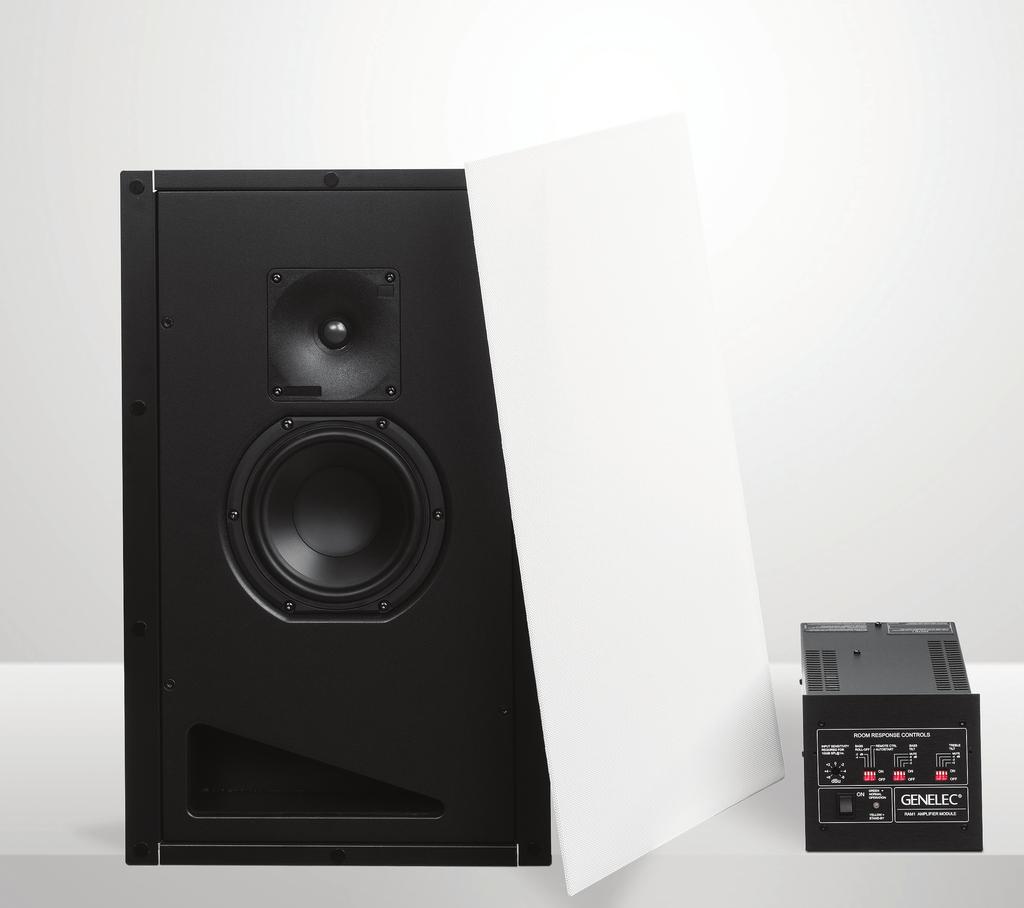
2 Genelec AIW26B Operating Manual Introduction Installation The Genelec AIW26B Active In-wall loudspeaker system consists of a bass reflex type two-way loudspeaker and a matched remote amplifier module, RAM1. It The AIW26B can be used in the most demanding applications, like the main L-C-R array of a Home Theater system, critical Stereo listening or rear/side channels of a large, state-of-the-art Home Theater. Unpacking A Genelec AIW26B set includes the items listed below. Check that nothing is missing or damaged during transport and delivery. If there is a problem with the product, contact your local Genelec dealer. AIW26B loudspeaker unit. Grille AIW26B cardboard cut-out template RAM1 amplifier unit Mains power cable Plexiglass cover for the control switches This Operating Manual Genelec recommends that you use the services of an authorized installation specialist or other competent and experienced installation company for the installation of the AIW26B system. Ask your local Genelec dealer for recommended installation companies in your region. Matching loudspeakers and amplifiers Each AIW26B loudspeaker unit has been factory calibrated for optimum performance with the RAM1 amplifier it is shipped with. Never mix these matched amplifierloudspeaker systems in the installation process. The matching units are marked with the same ID number on the reflex port of the AIW26B enclosure and the top panel of the RAM1. Loudspeaker placement Genelec AIW26B loudspeakers are equipped with Genelec s proprietary Directivity Control Waveguide (DCW). One of the main characteristics of the DCW technology is that the loudspeakers give a very even and consistent frequency response over a larger listening area than Figure 1. Symmetrical L-C-R loudspeaker placement conventional loudspeakers. A secondary function of the DCW is to reduce the off-axis radiated sound energy, thereby minimizing the reflections from the side walls, floor and ceiling. This results in a precise and stable sound image If the AIW26B loudspeakers are used in an application where their capability for precise sound imaging is needed, such as the front channels of a Surround Sound system or a Stereo system, we recommend that the loudspeakers are placed as far as possible from wall corners and other reflective


3 Figure 3. Connect the loudspeaker cable. Figure 2. Lift the AIW26B enclosure into the hole. Figure 4. Loudspeaker cable in place. Figure 5. Tighten the four Torx T25 screws to 1.5 Nm (1.1 lb ft). surfaces. The loudspeakers should be placed symmetrically in relation to the listening position and there should be no obstructions between the loudspeaker and the listener. This guarantees clear dialogue in films and a good stereo image with music. Figure 1 shows a Left-Center-Right arrangement that works well both as Surround Sound front channels and a Stereo pair. Whole house audio installations might require less stringent placement options. In these cases be sure to consult this manual for dip switch settings near boundary conditions in Table 3. Side and rear channel speaker placement in home theaters should follow the practical guidelines given in 5.1, 7.1 and 3D audio configurations. Painting the loudspeakers The metal mesh grille can be spray painted to match the wall colour. Do not paint the loudspeaker enclosure itself, or try to paint the grille while it is attached to the loudspeaker. Remove the thin cloth attached to the grille to avoid clogging the grille with paint. Paint the grille with a thin spray. Do not use brushes or rollers. Be very careful not to clog the holes on the mesh with paint. Installing the AIW26B loudspeaker enclosure AIW26B specific pre-construction brackets are available at your Genelec dealer. In the following we describe the installation procedure into an existing wall. Use the cardboard wall cut-out template to find the location for the AIW26B. The template also shows the position of the loudspeaker drivers, so you can easily find the placement that brings them to the optimum position as outlined in chapter Loudspeaker placement. Examine the wall structure carefully to find a clearly unobstructed location for the loudspeaker. The loudspeaker enclosure requires a minimum of 102 millimeters (4 in) of free depth measured from the surface of the drywall. Note that the grille is slightly wider and taller than the hole and requires about 30 millimeters (1 1/16 in) of smooth wall surface around all sides of the hole. When you have found a good location, check that the template is level and trace the hole onto the wall with a pencil along the outline of the template. If you are not sure that the chosen part of wall is free from obstructions, you can start by making a smaller hole at the center of the marked area through which you can probe the inside of the wall. Use a drywall saw and make the first cut at a 45 angle toward the center of the hole so you can put the cut piece back in if the location is unsuitable. If you find no obstructions, you can make the final cut along the marked lines. If you have already connected the RAM1 amplifier units to the system, select the loudspeaker that has the same ID number as the amplifier it will be driven by. Lift the loudspeaker into the hole lower end first and connect the loudspeaker cable connectors! Push the AIW26B loudspeaker into the hole and turn the four Torx T25 screws clockwise so that the mounting tabs rotate outwards. Continue tightening the screws to to 1.5 Nm (1.1 ft lb) and the drywall is firmly clamped between the mounting tabs and the enclosure flange. If necessary, a secondary support line can be attached to the tab on the top side of the enclosure. Next place the grille on the enclosure. The grille is held in place by magnets.

4 TWEETER WOOFER - - TWEETER TWEETER WOOFER WOOFER Figure 7. Correct loudspeaker cable polarity. Figure 6. The metal mesh grille is held in place by magnets. Choosing and installing the loudspeaker cables The RAM1 amplifier unit has separate power amplifiers for the tweeter and woofer. Accordingly, there are two pairs of binding posts, white (-) and red () for the tweeter and black (-) and grey () for the woofer. At the loudspeaker end, the cables are connected to a screw block terminal, which plugs into the input connector on the loudspeaker enclosure. Be sure to maintain correct polarity when connecting the loudspeaker cables and be extra careful not to mix the tweeter and woofer cables (See Figure 7). Use a good quality 4-conductor cable and make the cable runs as short as possible. See Table 1 for recommended cable gauges. The terminals accept a cable up to 6 mm 2 (9 gauge). If you are installing the AIW26B system to an existing wall, examine the walls thoroughly for the shortest and least obstructed cable route. Be careful to avoid cutting or drilling into electrical wires, ventilation or water pipes. These are often visible in the attic, basement or crawl space below the floor. It is a good idea to route the loudspeaker cables away from electric or video cables, which might induce hum into the loudspeaker system. Connecting the RAM1 amplifier The RAM1 amplifier is designed to be connected to a line level output of a preamplifier, Surround Sound processor or other low level source. NOTE! Never Cable gauge Max. length 2,0 mm 2 (14 AWG) 30 m (100 ft) 3,3 mm 2 (12 AWG) 40 m (130 ft) 5,3 mm 2 (10 AWG) 60 m (200 ft) Table 1. Recommended cable thicknesses for different lengths of loudspeaker cable. connect the RAM1 to a loudspeaker level output of a power amplifier! Before making the connections, check that the voltage selector on the amplifier s back panel is set to the correct voltage and the power on all components is turned off. Start by connecting the loudspeaker cables to the amplifier s binding posts (see Fig. 7 and 9). Check that the amplifier s serial number matches that of the AIW26B loudspeaker enclosure which it will power. The number can be found on a sticker on the loudspeaker s reflex port and on the amplifier s top cover. If the loudspeakers are not yet installed, make a note of which amplifier is connected to each channel. Check the cable polarity and use the provided cable binding post tool to tighten the binding posts. Be careful not to overtighten the binding posts as they may be damaged. The RAM1 has two parallel 10 kohm input connectors: a balanced XLR and an unbalanced RCA. For longer cable connection lengths (>10m or >30ft) a balanced line connection is recommended as it offers better immunity to external interference. The RCA connection method usually works as well for shorter connection lengths in less electrically noisy environments. Do not use both inputs at the same time. Consult your Genelec dealer for the choice of signal cables. The RAM1 has a provision for remote controlled switching between and STANDBY modes (not available in units sold in the EU). The REMOTE CTROL connector block has two connector pairs: 1 for a 12 V DC trigger remote control and 3 for an external switch or relay type (contact closure) remote control (see Table 2). Do not connect two remote controls to the amplifier at the same time. Space requirement for the RAM1 amplifier The dual 120 W power amplifiers of a RAM1 unit generate a large amount of heat when used at full power. To avoid overheating, ensure that there is good airflow around the amplifier and no external heat sources close to it. We recommend installing the RAM1 into a well ventilated equipment rack using its dedicated RM1 4U rack mount kit. If the RAM1 amplifier is placed in a cabinet, on a shelf or into an equipment rack without its dedicated RM1 rack mount kit, there must be at least 100 mm (4 in) of free space behind, 150 mm (6 in) above and 50 mm (2 in) on both sides of the amplifier to ensure adequate cooling (see figure 10). Mounting the RAM1 amplifier to an equipment rack We recommend that you use the Genelec RM1 4U rack mount kit when installing the RAM1 amplifier in an equipment rack. Make sure that the space above and below the RAM1 is uncluttered and there is a space of 100 mm (4 in) or more behind the amplifier. The space behind the amplifier must be well ventilated. If the temperature inside the rack is likely to rise close to the RAM1 s maximum ambient temperature of 35 C (95 F), we recommend installing ventilation fans to ensure that the thermal protection is not activated prematurely. See figure 11. Setting the input sensitivity The input sensitivity of each amplifier can be made to match that of the decoder or other source by use of the input sensitivity control on the amplifier s front panel (see

5 ROOM RESPSE CTROLS INPUT SENSITIVITY BASS REMOTE CTRL BASS REQUIRED FOR ROLL- AUTOSTART TILT 100dB db MUTE -6 db -6 dbu GREEN = NORMAL OPERATI YELLOW = STAND-BY RAM1 AMPLIFIER MODULE TREBLE TILT MUTE db 2 INPUT SENSITIVITY REQUIRED FOR 100dB SPL@1m. ROOM RESPSE CTROLS BASS REMOTE CTRL BASS ROLL- AUTOSTART TILT db MUTE -6 db OPERATI YELLOW = STAND-BY TREBLE TILT MUTE db 2 BASS ROLL-, AUTOSTART AND REMOTE CTROL SWITCHES (WHERE APPLICABLE) BASS TILT SWITCHES TREBLE TILT SWITCHES SENSITIVITY ADJUSTMENT MAINS POWER SWITCH STATUS INDICATOR LED dbu GREEN = NORMAL RAM1 AMPLIFIER MODULE Figure 8. Front panel of the RAM1 amplifier. Units sold in the EU have no Autostart and Remote Control functions. Figure 9. Rear panel of the RAM1 amplifier. Units sold in the EU have no Autostart and Remote Control functions. 150 (5 7/8 in) 50 (2 in) (2 in) 100 (4 in) Figure 10. Minimum space requirement of the RAM1 amplifier when not installed with Genelec RM1 rack mount. Figure 11. The optional Genelec RM1 4U rack mount holds up to three RAM1 amplifiers. figure 8). A small screwdriver is needed for the adjustment. The manufacturer default setting for this control is -6 dbu (0.389V, fully clockwise) which gives SPL of 100 with -6 dbu input level. Note that to get the full output level of 110 db SPL, an input level of 4 dbu (1.22V) is needed in this setting. Most pre-amplifiers are capable of this output level. Setting the room response controls The acoustic response of the system may have to be adjusted to match the acoustic environment and personal taste. See Table 3 for suggested room response control settings. If the sound is found subjectively too bright, set treble tilt to db, if too bass heavy, set bass tilt to db. The adjustment is done by setting the three groups of room response control switches treble tilt, bass tilt and bass roll-off on the front panel of the amplifier. The manufacturer default settings for all controls are All Off to give a flat response in half space, i.e. when the loudspeaker has been installed in a wall. Always start adjustment by setting all switches to the position. Then set only one switch within each group to the position to select the desired response curve. The switches are not cumulative. If more than one switch is set to (within one switch group) the attenuation value is not accurate. See Table 3 for some recommended settings. Using Autostart and Remote Control functions Autostart and Remote Control functions are not available in units sold in the EU. The RAM1 amplifier can be switched to STANDBY mode by activating the signal sensing Autostart function or by a remote control unit (not included in the AIW26B system). If the system is left unused for Remote Pole or Connect to control type contact remote control input pin no. 12 V DC 1 trigger - 2 voltage External Contact 1 3 switch or Contact 2 4 relay Connect only one remote control unit at a time Table 2. Remote control connectors on the RAM1. several days, power it down using the RAM1 s main power switch or a central power switch if one has been installed. The Autostart function is activated by turning switch 4 (AUTOSTART) on the first switch group to. Autostart turns the amplifier to STANDBY mode if there is no signal present for about 30 minutes. When the signal returns the amplifier switches on immediately and the loudspeaker functions normally. If you are using a remote control to switch the RAM1 between STANDBY or modes (see chapter Connecting the RAM1 amplifier ), turn switch 3 (REMOTE CTROL), on the first switch group to. This activates the remote control function. In this setting the remote control will override the Autostart function. If you want to use Autostart, turn the REMOTE CTROL switch to. Protecting the settings The control group of the RAM1 can be covered with a piece of plexiglass to protect
6 WOOFER WOOFER TWEETER TWEETER - - Bass Roll-Off Bass Tilt Treble Tilt Half space factory default setting ALL ALL ALL 350 mm (13 3/4 in) Well damped (dead sounding) room 0 db 0 db 0 db Normal room 0 db 0 db db Highly reflective (live sounding) room 0 db db db Additional settings to compensate the loudspeaker positioning within the room In a double corner (wall/wall or wall/ceiling) db db 0 db In a triple corner (wall/wall/ceiling) db db 0 db If the loudspeaker is positioned behind a perforated screen, add 2 db to the Treble Tilt setting to compensate Table 3. Suggested room response control settings for differing acoustical environments 574 mm (22 5/8 in) the settings. Attach the plexiglass over the switch groups with two Phillips screws when you have completed the adjustments. Do not overtighten the screws. Status indicator LED The status indicator LED on the RAM1 changes colour to indicate amplifier status. If the LED is yellow, it indicates that the amplifier is in STANDBY mode. When the amplifier is switched to mode, the LED changes to green colour. Automatic protection circuits The AIW26B system has protection circuits against loudspeaker driver thermal overload and amplifier overheating. The protection system resets automatically so the user only has to turn the input level down to ensure that it does not reactivate. Driver thermal overload protection protects the drivers from damage caused by prolonged overdriving with excessively high or distorted signal. The circuit automatically reduces the volume of the channel that is being overloaded. To avoid this, lower the listening volume if the sound becomes harsh and distorted at high sound pressure levels. Amplifier thermal protection turns the amplifier to STANDBY mode if the amplifier overheats. Let the amplifier cool down and check that there is sufficient clearance around the amplifier for cooling (see chapters Space requirement for the RAM1 amplifier and Mounting the RAM1 amplifier to an equipment rack above). If the problem persists, consult your Genelec dealer or Home Theater Installation company for an improved cooling solution for your equipment cabinet or rack. Maintenance There are no user serviceable parts within the loudspeaker or the amplifier. Any maintenance or repair should only be undertaken by qualified Genelec service personnel. Safety considerations Servicing and adjustment must only be performed by qualified Genelec service personnel. Do not undo any screws on the amplifier unit. It is forbidden to use this product with an unearthed power cable, which may lead to personal injury. To prevent fire or electric shock, do not expose any part of the system to water or moisture. Do not place any objects filled with liquid, such as vases, on the RAM1 amplifier or near it. Switch off the mains power from the amplifier if the system is not used for long periods of time. Note that the RAM1 amplifier is not completely disconnected from the AC mains service unless the mains power cable is removed from the amplifier or the mains outlet. WARNING! This equipment is capable of delivering Sound Pressure Levels in excess of 85 db, which may cause permanent hearing damage. Guarantee This product is supplied with a two year guarantee against manufacturing faults or defects that might alter the performance of the unit. Refer to supplier for full sales and guarantee terms. Figure 12. AIW26B front view 103 mm (4 1/16 in) 548 mm (21 9/16 in) Figure 13. AIW26B side view 300 mm (11 13/16 in) 100 mm (3 15/16 in) 157 mm (6 3/16 in) Figure 14. AIW26B top view 74 mm (2 7/8 in)
7 AIW26B LOUDSPEAKER UNIT RAM1 AMPLIFIER UNIT Lower cut-off frequency, -6 db: < 39 Hz Bass amplifier output power: Short term 120 W Upper cut-off frequency, -6 db: > 25 khz Treble amplifier output power: Short term 120 W Accuracy of frequency response, (±2.5 db): 45 Hz...21 khz Input impedance: 10 kohm Maximum short time sine wave acoustic output at 1 m on axis in half space, averaged from 100 Hz to 3 khz: Maximum peak acoustic output for a pair with music material: Drivers Bass: Treble: Harmonic distortion at 90 db 1 m on axis: Weight including grille assembly: Required cut-out dimensions Height: Width: Depth: Permissible drywall panel thickness: >110 db SPL >120 db SPL 165 mm (6.5 in) 19 mm ( 3 /4 in) metal dome < 3% ( Hz) < 0.5% (>200 Hz) 8.7 kg (19.2 lbs) 552 mm (21 3 /4 in)* 303 mm (11 15 /16 in) 102 mm (4 in)** 7-28 mm ( 1 /4 in /8 in ** The grille is taller and wider than the cut-out and requires 30 mm (1 1/16 in) of smooth wall surface around all sides of the cut-out. ** Depth = Free space requirement inside the wall cavity measured from the surface of the drywall. Crossover frequency: Treble tilt control in 2 db steps from 2 to db & MUTE: Bass roll-off control in 2 db steps from 0 to -6 db: Bass tilt control in 2 db steps from 0 to -6 db & MUTE: Mains voltage: Power consumption (Standby / Idle / Full output): Maximum ambient temperature Weight: Dimensions Height: Width: Depth: 3.5 Hz 100/200 V or 115/230 V 23/23/200 W 35 C (95 F) 4.6 kg (10.1 lbs) 130 mm (5 1 /8 in) 145 mm (5 3 /4 in) 309 mm (12 3 /16 in) 365 (14 3/8 in) 145 (5 3/4 in) 137 (5 3/8 in) 281 (11 1/16 in) Figure 16. RAM1 top view 309 (12 3/16 in) 589 (23 3/16 in) 130 (5 1/8 in) 117 (4 5/8 in) Figure 15. AIW26B grille front view. The thickness of the grille is 4 mm (3/16 in). Figure 17. RAM1 side view
8 AIW26B Operating Manual Genelec Document D0132R AIW26B. Copyright Genelec Oy All data subject to change without prior notice. International enquiries: Genelec Oy, Olvitie 5 FIN-74100, Iisalmi, Finland Phone Fax genelec@genelec.com In the U.S. please contact: Genelec, Inc., 7 Tech Circle Natick, MA 01760, USA Phone Fax genelec.usa@genelec.com In China please contact: Beijing Genelec Audio Co, Ltd. Room 101, 1st Floor Building 71 B33 Universal Business Park No.10 Jiuxianqiao Road, Chaoyang District, Beijing , China Phone 86 (10) , Post code genelec.china@genelec.com
AIC25. Operating Manual Genelec AIC25 Active In-Ceiling Loudspeaker
 AIC25 Operating Manual Genelec AIC25 Active In-Ceiling Loudspeaker Genelec AIC25 Active In-Ceiling Loudspeaker The Genelec AIC25 Active In-Ceiling loudspeaker system consists of a two-way loudspeaker enclosure
AIW25. Operating Manual Genelec AIW25 Active In-Wall Loudspeaker
 AIW25 Operating Manual Genelec AIW25 Active In-Wall Loudspeaker EC Declaration of Conformity This is to certify that the Genelec AIW25 Active In-Wall Loudspeaker conforms to the following standards: Safety:
4020B. Operating Manual
 4020B Operating Manual 4020B Active Loudspeaker General The bi-amplified Genelec 4020B is an extremely compact two way active loudspeaker designed for fixed installations. As an active loudspeaker, it
7040A. Operating Manual Genelec 7040A Active Subwoofer
 Operating Manual Genelec Active Subwoofer Genelec Active Subwoofer Introduction Congratulation and thank you for choosing Genelec! Since 1978, Genelec has been guided by a single idea to make perfect active
8000 Series. Operating Manual Genelec 8040A and 8050A Monitoring Systems
 8000 Series Operating Manual Genelec 8040A and 8050A Monitoring Systems Genelec 8040A and 8050A Monitoring Systems System The GENELEC 8040A and 8050A are two way active monitoring loudspeakers designed
1037C and 1038B. Operating Manual Genelec 1037C and 1038B Tri-amplified Monitoring Systems
 137C and Operating Manual Genelec 137C and Tri-amplified Monitoring Systems Genelec 137C and Tri-amplified Monitoring Systems System The Genelec 137C and are threeway active monitoring systems including
HT312B and HT315B. Operating Manual Genelec HT312B and HT315B Active 3-Way Speaker Systems
 HT312B and HT315B Operating Manual Genelec HT312B and HT315B Active 3-Way Speaker Systems Genelec HT312B and HT315B Active 3-Way Speaker Systems System The Genelec HT312B and HT315B are threeway active
4010A. Operating Manual
 4010A Operating Manual Operating Manual General The bi-amplified Genelec 4010A is an extremely compact two way active loudspeaker designed for fixed installations. It contains drivers, power amplifiers,
1238AC. Operating Manual Genelec 1238AC Smart Active Monitor
 1238AC Operating Manual Genelec 1238AC Smart Active Monitor Genelec 1238AC Operating Manual Introduction Congratulations and thank you for choosing Genelec! Since 1978, Genelec has been guided by a single
4020C. Operating Manual
 4020C Operating Manual General The bi-amplified Genelec 4020C is an extremely compact two way active loudspeaker designed for fixed installations. As an active loudspeaker, it contains drivers, power amplifiers,
4030C. Operating Manual
 4030C Operating Manual General The bi-amplified Genelec 4030C is an extremely compact two way active loudspeaker designed for fixed installations. As an active loudspeaker, it contains drivers, power amplifiers,
HT330A. Operating Manual Genelec HT330A Three-Way Active Loudspeaker
 HT330A Operating Manual Genelec HT330A Three-Way Active Loudspeaker System The GENELEC HT330A active loudspeaker is designed for neutral sound reproduction at high SPLs in large Home Theater rooms. The
Classic Active Monitoring Series. Catalogue 2018
 Classic Active Monitoring Series Catalogue 2018 8000 Series DCW Directivity Control Waveguide The revolutionary DCW provides extremely accurate control of the onand off-axis response over a wide bandwidth.
1039A. Operating Manual Genelec 1039A Control Room Monitoring System
 1039A Operating Manual Genelec 1039A Control Room Monitoring System System The GENELEC 1039A monitor is designed for neutral sound reproduction at high SPLs in large control rooms. The system comprises
Genelec 1034B Control Room Monitoring System. Operating Manual
 Genelec 1034B Control Room Monitoring System Operating Manual 1. DESCRIPTI The GENELEC 1034B monitor is designed for neutral sound reproduction at high SPLs in large control rooms. The system comprises
Genelec S30D Digital Monitoring System. Operating Manual
 Genelec S30D Digital Monitoring System Operating Manual S30D Digital Monitoring System 1. General description The Genelec S30D is a three-way Digital Monitoring System including a digital audio interface,
8341A Smart Active Monitor. Operating Manual
 8341A Smart Active Monitor Operating Manual Introduction Thank you for choosing a Genelec product! Fulfilling dreams by offering people the most truthful sound reproduction possible has been the source
SM 50Ak. 2 way nearfield active monitor owners manual.
 2 way nearfield active monitor owners manual www.sonodyne.com Introduction Safety Unpacking Fig 1 & 2 INTRODUCTION Congratulations on your purchase of the near field active studio monitor. The has all
User Manual. MA 240 Mixing amplifier
 User Manual MA 240 Mixing amplifier Safety instructions When using this electronic device, basic precautions should always be taken, including the following: 1 Read all instructions before using the product.
User Manual. ia480x Power amplifier
 User Manual ia480x Power amplifier Safety instructions When using this electronic device, basic precautions should always be taken, including the following: 1 Read all instructions before using the product.
User Manual. MA 21 Two zone mixing amplifier
 User Manual MA 21 Two zone mixing amplifier Safety instructions When using this electronic device, basic precautions should always be taken, including the following: 1 Read all instructions before using
1032C Smart Active Monitor. Operating Manual
 Smart Active Monitor Operating Manual Introduction Congratulations and a thank you for the purchase of this Genelec Smart Active Monitor (SAM ) system. This manual addresses the stand-alone setup and use
A32. f u l l y b a l a n c e d p o w e r a m p l i f i e r. user guide
 A32 f u l l y b a l a n c e d p o w e r a m p l i f i e r user guide Welcome! Welcome to the Primare A32 Amplifier! The A32 is a modular power amplifier designed as the ideal output stage in a home theatre
musikelectronic geithain RL 930K Instructions for installation and use
 musikelectronic geithain Instructions for installation and use 2 Table of contents 1 Introduction 3 2 System description 4 3 Basic information 5 3.1 Guidelines 5 3.2 Safety instructions 5 3.3 Unboxing
IMPORTANT SAFETY INSTRUCTIONS
 IMPORTANT SAFETY INSTRUCTIONS When using this electronic device, basic precautions should always be taken, including the following: 1. Read all instructions before using the product. 2. Do not use this
PROFESSIONAL STEREO AMPLIFIERS USER GUIDE
 PROFESSIONAL STEREO AMPLIFIERS USER GUIDE 967/9673 - September 00 - Version.0 ENGLISH Ti SERIES - Professional stereo amplifiers Page Ti SERIES - Professional stereo amplifiers ENGLISH - Safety information
IMPORTANT SAFETY INSTRUCTIONS
 IMPORTANT SAFETY INSTRUCTIONS When using this electronic device, basic precautions should always be taken, including the following: 1. Read all instructions before using the product. 2. Do not use this
Monolith. Subwoofer System OWNERS MANUAL
 Monolith Subwoofer System OWNERS MANUAL CONTENTS Page No. 1) Safety instructions. 2) 3) 4) Connecting up your Monolith. Connecting up using the high level input. Connecting up using the low level input.
STUDIO PRECISION DIRECT FIELD MONITOR SYSTEM
 STUDIO PRECISION DIRECT FIELD MONITOR SYSTEM 2 Thank you for choosing the Studio Precision Direct Field Monitor System. To get the most from your new monitors, please take a moment to read this manual
KLASIK NEAR FIELD ACTIVE STUDIO MONITOR
 USER S MANUAL KLASIK NEAR FIELD ACTIVE STUDIO MONITOR CONTENTS page INTRODUCTION GENERAL INFORMATION 3 REAR PANEL REAR PANEL 4 INPUTS 5 SWITCHES 5 TECHNICAL SPECIFICATIONS TECHNICAL SPECIFICATIONS 7 SAFETY
1160 Stereo Power Amplifier
 1160 Stereo Power Amplifier 03/01/2018 Rev. 1.0 P/N: 91055 Boulder Amplifiers, Inc. 255 S. Taylor Ave. Louisville, CO 80027 (303) 449-8220 www.boulderamp.com About About Boulder Amplifiers, Inc. Boulder
Opus 21 s80 Integrated Amplifier Owner's Manual
 Opus 21 s80 Integrated Amplifier Owner's Manual r e s o l u t i o n From all of us at Resolution Audio, thank you for choosing the Opus 21 s80 amplifier. We went to great lengths to design and produce
AV30MX-2 Operation Manual
 AV30MX-2 Operation Manual 1 Important safety instructions 1. Please read carefully prior to product installation or operation. 2. Read these instructions. 3. Keep these instructions. 4. Heed all warnings.
Big Bang. B B O w n e r s M a n u a l. Power Amplifiers. SpeakerCraft BB2125 POWER ACTIVE PROTECTION L
 Big Bang Power Amplifiers SpeakerCraft BB2125 ACTIVE POWER PROTECTION L R B B 2 1 2 5 O w n e r s M a n u a l SAFETY INSTRUCTIONS APPLICABLE FOR USA, CANADA OR WHERE APPROVED FOR USAGE CAUTION: To reduce
musikelectronic geithain RL 901K ME 901K Instructions for installation and use
 musikelectronic geithain RL 901K ME 901K Instructions for installation and use TABLE OF CONTENTS 2 Table of contents 1 Introduction 3 2 System description 4 3 Basic information 5 3.1 Guidelines 5 3.2 Safety
VAS35P / VAS36P SHAKER LOUDSPEAKER SYSTEMS
 VAS35P / VAS36P SHAKER LOUDSPEAKER SYSTEMS Thank you for your interest in VM Audio products. Our goal is to enhance your listening experience. The Shaker Series was designed as the economical solution
plifier D-501 otion Am Tactile M
 Tactile Motion Amplifier D-501 IMPORTANT SAFETY INSTRUCTIONS WARNING: 1. Read and keep these instructions for future reference. 2. Do not use this apparatus near water. 3. Clean only with a dry cloth.
REVAMP4100 Instruction manual
 REVAMP4100 Instruction manual REVAMP4100 Instruction manual 3 REVAMP4100 manual 4 CLASS-D POWER AMPLIFIER IMPORTANT SAFETY INSTRUCTIONS 1. Read these instructions 2. Keep these instructions 3. Heed all
SAGA PRO SERIES STEREO POWER AMPLIFIER OPERATION MANUAL
 SAGA PRO SERIES STEREO POWER AMPLIFIER OPERATION MANUAL INSTALLATION Use care in unpacking the amplifier, and be sure to save the carton and packing materials so that you can use them for moving, storing,
3050 Stereo Power Amplifier
 3050 Stereo Power Amplifier Owners Manual 10/26/2016 Boulder Amplifiers, Inc. 255 Taylor Ave. Louisville, CO 80027 (303) 449-8220 www.boulderamp.com Fault Conditions Boulderlink Appendix Remote Control
V6 V10 V35 V45 V218-S V221-S
 OWNER MANUAL V6 V10 V35 V45 V218-S V221-S VMAX SERIES LOUDSPEAKERS TABLE OF CONTENTS SAFETY AND OPERATING PRECAUTIONS DESCRIPTION CONNECTIONS SPECIFICATIONS DIMENSIONS 4 6 7 9 10 ENGLISH SAFETY PRECAUTIONS
The New 8260A Three-Way DSP Loudspeaker System. with Minimum Diffraction Coaxial (MDC ) Technology
 Technology") The New 8260A Three-Way DSP Loudspeaker System with Minimum Diffraction Coaxial (MDC ) Technology The New 8260A Three-Way DSP Loudspeaker System with Minimum Diffraction Coaxial (MDC ) Technology Masterpiece
The New 8260A Three-Way DSP Loudspeaker System with Minimum Diffraction Coaxial (MDC ) Technology The New 8260A Three-Way DSP Loudspeaker System with Minimum Diffraction Coaxial (MDC ) Technology Masterpiece
AELIUS YPSILON POWER AMPLIFIER. OWNERS MANUAL V1 01/01/20010 All rights reserved
 AELIUS YPSILON POWER AMPLIFIER OWNERS MANUAL V1 01/01/20010 All rights reserved INTRODUCTION Thank you for trusting YPSILON ELECTRONICS. We assure you that you have made an excellent purchase. Your amplifier
Amplifier Series BASIC. Installation & Operations Manual
 Amplifier Series BASIC Installation & Operations Manual Bittner-Audio 200 Power Amplifier Series BASIC Bittner - Audio September 200 200 Bittner-Audio. All Rights Reserved. Bittner-Audio reserves specification
EPA104/254. User Manual.
 EPA104/254 User Manual www.audac.eu ADDITIONAL INFORMATION This manual is put together with much care, and is as complete as could be on the publication date. However, updates on the specifications, functionality
PROFESSIONAL SMPS STEREO AMPLIFIERS USER GUIDE
 PROFESSIONAL SMPS STEREO AMPLIFIERS USER GUIDE 987/988/989 - December 00 - Version.0 English SMi series - Professional SMPS stereo amplifiers - Safety information Important safety information This unit
2BSST POWER AMPLIFIER OWNER S MANUAL
 2BSST POWER AMPLIFIER OWNER S MANUAL IMPORTANT SAFETY INSTRUCTIONS The lightning flash with arrowhead symbol within an equilateral triangle, is intended to alert the user to the presence of un-insulated
léìë=on ëpm=fåíéöê~íéç=^ãéäáñáéê lïåéêdë=j~åì~ä êéëçäìíáçå
 léìë=on ëpm=fåíéöê~íéç=^ãéäáñáéê lïåéêdë=j~åì~ä êéëçäìíáçå From all of us at Resolution AV, thank you for choosing the Opus 21 s30 amplifier. We went to great lengths to design and produce an integrated
DPA-1200 ORDERCODE D4180 DPA-2400 ORDERCODE D4181 DPA-3400 ORDERCODE D4182
 Digital DPA-1200 DPA-2400 DPA-3400 ORDERCODE D4180 ORDERCODE D4181 ORDERCODE D4182 Congratulations! You have bought a great, innovative product from DAP Audio. The Dap Audio Vintage Digital Power Series
M-300 Mono power amplifier User s guide
 M-300 Mono power amplifier User s guide M-300 Mono power amplifier User s guide Specifications: Contents: Power output: 8Ω: 290W, 0.01% THD SPECIFICATIONS Page 2 Input impedance: Gain: 4Ω: 580W, 0.01%
POWERED MONITOR SPEAKER MSP10STUDIO
 POWERED MONITOR SPEAKER MSP10STUDIO Owner s manual Mode d emploi Bedienungsanleitung Manual de instrucciones M Thank you for purchasing the Yamaha MSP10STUDIO powered monitor speaker system. The MSP10STUDIO
Professional Stereo Amplifiers
 Symbol 12000 Professional Stereo Amplifiers ENGLISH FBT elettronica S.p.A. - Via Paolo Soprani 1 - Zona Ind.le Squartabue - 62019 RECANATI (MC) - ITALY TEL. 071/750591 r.a. - FAX 071/7505920 - http://www.fbt.it
POWER AMPLIFIER. Owner s Manual Mode d emploi Bedienungsanleitung Manual de instrucciónes CLIP SIGNAL TEMP PROTECTION POWER
 POWER AMPLIFIER Owner s Manual Mode d emploi Bedienungsanleitung Manual de instrucciónes TEMP PROTECTION POWER A CLIP SIGNAL B ON OFF M Introduction Thank you for purchasing a Yamaha C450/320/160 series
Owner s Manual B 300 B 600 B 900 B 1200 B 1500 B 902 B 1202 B 1802 B300 B1802
 Owner s Manual B 300 B 600 B 900 B 1200 B 1500 B300 B 902 B 1202 B 1802 B1802 WARNING B 300 / B 600 / B 900 / B 1200 / B 1500 / B 902 / B 1202 / B 1802 Table of Contents Table of Contents Introduction
EPA152/252/502. User Manual.
 EPA152/252/502 User Manual www.audac.eu ADDITIONAL INFORMATION This manual is put together with much care, and is as complete as could be on the publication date. However, updates on the specifications,
R-Series R235LS 2-Channel Power Amplifier with Local Source Switching
 R-Series R235LS 2-Channel Power Amplifier with Local Source Switching User s Manual On Off R235LS POWER A MPLIFIER IMPORTANT SAFEGUARDS WARNING TO REDUCE THE RISK OF FIRE OR ELECTRIC SHOCK, DO NOT EXPOSE
AV Series AV-25-2 AV-25 Owner s Manual February 2010
 AV Series AV-25-2 AV-25 Owner s Manual February 2010 www.stewartaudio.com Important Safety Instructions Before using your Stewart Audio Inc. Power Amplifier, please read this Owner s Manual carefully to
STEREO POWER AMPLIFIER OWNER MANUAL PR-150 DESIGNED IN U.K. PDF created with FinePrint pdffactory trial version
 STEREO POWER AMPLIFIER OWNER MANUAL PR-150 DESIGNED IN U.K. INTRODUCTION Congratulations on your purchase of MA PR-150 Stereo Power Amplifier. The performance of PR-150 is perfect for any audio application,
Monitor Setup Guide The right monitors. The correct setup. Proper sound.
 Monitor Setup Guide 2017 The right monitors. The correct setup. Proper sound. Table of contents Genelec Key Technologies 3 What is a monitor? 4 What is a reference monitor? 4 Selecting the correct monitors
ECI 6D. Balanced Integrated Amplifier. Owner's Manual. (with a built-in DAC) ENGLISH
 ENGLISH") ECI 6D Balanced Integrated Amplifier (with a built-in DAC) Owner's Manual EN ENGLISH Unpacking the ECI 6D Immediately upon receipt of the ECI 6D, inspect the carton for possible damage during shipment.
ECI 6D Balanced Integrated Amplifier (with a built-in DAC) Owner's Manual EN ENGLISH Unpacking the ECI 6D Immediately upon receipt of the ECI 6D, inspect the carton for possible damage during shipment.
Q-Tech. Q-Tech Commercial Series QTA 1360P/1480P Power Amplifiers. User Manual
 Q-Tech Power Amplifiers WARNING THIS APPLIANCE MUST BE EARTHED General Installation DO NOT run unbalanced high impedance microphone cables near mains, data, telephone or 70/100V line cables. DO NOT run
ECA COMMERCIAL AMPLIFIER OWNER S MANUAL ECA-70MIXAMP V / 70V / 4Ω Amplifier ECA-70MIXAMP-1-60 OUTPUT LEVEL POWER MASTER MIC 1
 OWNER S MANUAL ECA COMMERCIAL AMPLIFIER ECA-MIXAMP--6 V / V / Ω Amplifier TEMP PROT OUTPUT LEVEL ECA-MIXAMP--6 6 POWER MIC MIC MIC MIC AUX AUX BASS TREBLE 5 5 5 5 5 6 6 6 6 6 MASTER 5 6 ON OFF + - + -
HT Watt 4 Channel Class D amplifier OWNER S MANUAL
 HT-4 600 Watt 4 Channel Class D amplifier OWNER S MANUAL Congratulations! Thank you for purchasing the Wet Sounds Hydro-Tech TM series amplifier. Wet Sounds represents the ultimate in high performance
UA ª 35T II Utility Amplifier OPERATING INSTRUCTIONS
 OPERATING INSTRUCTIONS Intended to alert the user to the presence of uninsulated "dangerous voltage" within the product's enclosure that may be of sufficient magnitude to constitute a risk of electric
HT Watt 6 Channel Class D amplifier OWNER S MANUAL
 HT-6 900 Watt 6 Channel Class D amplifier OWNER S MANUAL Congratulations! Thank you for purchasing the Wet Sounds Hydro-Tech TM series amplifier. Wet Sounds represents the ultimate in high performance
PROLUDE AMPLIFICATION D750. User s manual for the tube preamplifier version
 PROLUDE AMPLIFICATION D750 User s manual for the tube preamplifier version 1 2 Table of contents 1 INTRODUCTION...1 4 1.1 SOME WORDS TO THE CUSTOMER...1 4 1.2 SOME WORDS ABOUT ME...1 4 2 SAFETY INSTRUCTIONS,
poly-planar ME-51 Subwoofer Amplifier Waterproof Marine Audio
 ME-51 Subwoofer Amplifier 1 ME-51 Subwoofer Amplifier Introduction: The ME-51 is a dual channel mono audio amplifier capable of delivering 50W RMS (100W total music power). It is designed to be used with
A 4000 A Owner s Manual HPA HPA A4000 A5000 PROFESSIONAL POWER AMPLIFIER POWER CHANNEL 2 CHANNEL 1 PROFESSIONAL POWER AMPLIFIER POWER CHANNEL 2
 Owner s Manual A 000 A 000 PROFESSIAL POWER AMPLIFIER CHANNEL POWER PROTECT CLIP -0dB -0dB SIGNAL ACTIVE A000 CHANNEL HPA 0 9 0 9 9 0 9 0 9 9 PROFESSIAL POWER AMPLIFIER CHANNEL POWER PROTECT CLIP -0dB
TOA 500 SERIES MIXER POWER AMPLIFIER
 TOA 500 SERIES MIXER POWER AMPLIFIER Operation Instruction Manual A-503A A-506A A-512A Features General Description 1. High quality design and construction. 2. Full frequency response: 50-15,000Hz, ±3dB.
AV25-2 User Manual. 1 Important safety instructions
 AV25-2 User Manual 1 Important safety instructions 1. Please read carefully prior to product installation or operation. 2. Read these instructions. 3. Keep these instructions. 4. Heed all warnings. 5.
XLS200. Subwoofer System OWNERS MANUAL
 XLS200 Subwoofer System OWNERS MANUAL CONTENTS Page No. 1) Safety instructions. 2) 3) 4) Connecting up your XLS200. Connecting up using the high level input. Connecting up using the low level input. 5)
MC450/MC650 (MC750) OPERATING INSTRUCTIONS
 OPERATING INSTRUCTIONS") MC450/MC650 (MC750) OPERATING INSTRUCTIONS MC 2 AUDIO Ltd., Units 6 & 7 Kingsgate, Heathpark Industrial Estate, HONITON, Devon EX14 1YG England Tel: ++(0)1404.44633 Fax: ++(0)1404.44660 www.mc2-audio.co.uk
MC450/MC650 (MC750) OPERATING INSTRUCTIONS MC 2 AUDIO Ltd., Units 6 & 7 Kingsgate, Heathpark Industrial Estate, HONITON, Devon EX14 1YG England Tel: ++(0)1404.44633 Fax: ++(0)1404.44660 www.mc2-audio.co.uk
IMPORTANT SAFETY INSTRUCTIONS
 IMPORTANT SAFETY INSTRUCTIONS When using this electronic device, basic precautions should always be taken, including the following: 1. Read all instructions before using the product. 2. Do not use this
F O R T H E L O V E O F M U S I C LP100 OWNER'S MANUAL AND INSTALLATION GUIDE INTRODUCTION
 F O R T H E L O V E O F M U S I C LP100 OWNER'S MANUAL AND INSTALLATION GUIDE INTRODUCTION You have purchased an amplifier that leads the way with sound quality, reliability, and features. These high performance
C O N C O U R S E Q S E R I E S
 R E V.1 C O N C O U R S E Q S E R I E S INSTRUCTION BOOKLET CONCOURSE Q SERIES SUBWOOFER/Q SUB F O R T H E C L O S E S T A P P R O A C H T O T H E O R I G I N A L S O U N D TABLE OF CONTENTS Introduction:
SAFETY WARNINGS AND GUIDELINES INTRODUCTION
 SAFETY WARNINGS AND GUIDELINES Turn off and unplug all equipment prior to making electrical connections, including speaker wire connections. Reduce the volume level prior to making any change to the audio
Classic Series Public Address Amplifiers C10 & C20 Models
 Classic Series Public Address Amplifiers C10 & C20 Models Installation and Use Manual 2009 Bogen Communications, Inc. All rights reserved. Specifications subject to change without notice. 54-5978-01C 1106
USER MANUAL MG-TA1000 POWER AMPLIFIER
 USER MANUAL MG-TA1000 POWER AMPLIFIER INDEX: INTRODUCTION SAFETY INSTRUCTIONS OPERATING PRECAUTIONS FEATURES OF PANAL CONTROLS FRONT & REAR PPANEL DISPLAY CONNECTING INPUTS SPEAKER CONNECTIONS INTRODUCTION:
CX-A6 Amplifier Installation & User Guide V8.0
 CX-A6 Amplifier Installation & User Guide V8.0 Cloud Electronics Limited 140 Staniforth Road, Sheffield, S9 3HF England Tel + 44 (0) 114 244 7051 Fax + 44 (0) 114 242 5462 E-mail info@cloud.co.uk Web site
REVAMP2600 Instruction manual
 REVAMP2600 Instruction manual REVAMP2600 Instruction manual 3 REVAMP2600 MANUAL 4 PROFESSIONAL POWER AMPLIFIER Safety first! Caution! This professional device needs to be installed by qualified personnel
MIXER POWER AMPLIFIER BG-130
 OPERATING INSTRUCTIONS MIXER POWER AMPLIFIER BG-115 BG-130 TO REDUCE THE RISK OF ELECTRICAL SHOCK, DO NOT REMOVE COVER. NO USER SERVICEABLE PARTS INSIDE. REFER SERVICING TO QUALIFIED SERVICE PERSONNEL
TOA PROFESSIONAL POWER AMP
 Operating Instruction Manual TOA PROFESSIONAL POWER AMP Model P-150M, P-300M TOA ELECTRIC CO, LTD. KOBE, JAPAN Contents Precautions... 2 General Description... 2 Features... 3 Specifications... 4~5 Performance
The component shall reproduce the original musical sound, purely and naturally.
 a100 linear USER GUIDE Congratulations on your new CONSONANCE! Our products are based on a simple philosophy: The component shall reproduce the original musical sound, purely and naturally. The products
T L Audio. User Manual EQ1 VALVE EQUALISER. Tony Larking Professional Sales Limited, Letchworth, England.
 T L Audio User Manual EQ1 VALVE EQUALISER Tony Larking Professional Sales Limited, Letchworth, England. Tel: 01462 490600, International +44 1462 490600. Fax: 01462 490700, International +44 1462 490700.
CLASS D MONO AMPLIFIER GM-D8601 GM-D9601. Owner s Manual
 CLASS D MONO AMPLIFIER GM-D8601 GM-D9601 Owner s Manual Before you start BE SURE TO OBSERVE THE FOLLOWING GUIDELINES:! Do not turn up the volume so high that you can t hear what s around you.! Use caution
CX-A6 Amplifier Installation & User Guide V9.0
 CX-A6 Amplifier Installation & User Guide V9.0 Cloud Electronics Limited 140 Staniforth Road, Sheffield, S9 3HF England Tel + 44 (0) 114 244 7051 Fax + 44 (0) 114 242 5462 E-mail info@cloud.co.uk Web site
3400 Watt Stereo Power Amplifier
 3400 Watt Stereo Power Amplifier OWNER'S MANUAL Copyright 2014, Samson Technologies Corp. v1.1 Samson Technologies Corp. 45 Gilpin Ave Hauppauge, NY 11788 www.samsontech.com Important Safety Information
FreeSpace IZA 2120-LZ Integrated Zone Amplifier
 Product Description For background/foreground music and paging applications, Bose FreeSpace IZA 2120-LZ integrated zone amplifier elevates the audio experience when using FreeSpace loudspeakers. Optimized
MANUAL. Champ - 4. Professional quad power amplifier
 MANUAL Champ - 4 Professional quad power amplifier INFO@APART-AUDIO.COM Safety First! Caution: hot and sharp surfaces! This professional device needs to be installed by qualified personnel only. Please
SI-125 Power Amplifier Manual 6205 Kestrel Road; Mississauga, Ontario; Canada; L5T 2A1 November 2016, Rev 0.5
 SI-125 Power Amplifier Manual 6205 Kestrel Road; Mississauga, Ontario; Canada; L5T 2A1 November 2016, Rev 0.5 Phone: (905) 564-0801 Fax: (905) 564-0806 www.telecor.com E:\T2-108\T2-M108-ABC\T2-M108-B.doc/AD
For Accurate Music and Voice Reproduction from In-Ceiling Locations
 INSTALLATION & USER GUIDE For Accurate Music and Voice Reproduction from In-Ceiling Locations 6-1/2" IN-CEILING LOUDSPEAKER LSC-6 /6.5 LSC-6 / 6.5 6-1/2" IN-CEILING LOUDSPEAKER TABLE OF CONTENTS Features...1
CVA V. Owner s Manual May 2014 CVA V.
 CVA25-1 25V CVA25-1 25V www.stewartaudio.com Owner s Manual May 2014 Important Safety Instructions Before using your Stewart Audio Inc. Power Amplifier, please read this Owner s Manual carefully to ensure
SXD SXD SXD SXD Dynamic Audio
 SXD SXD SXD SXD SXD 1000.1 2000.1 1100.2 1600.4 Dynamic Audio Company Message Congratulations on the purchase of your new SXD Series amplifier. Our engineers designed your amplifier with performance in
Boulder W Class A Stereo Power Amplifier
 Boulder 2060 600 W Class A Stereo Power Amplifier Owners Manual V1.0 10/10/97 TABLE OF CONTENTS GETTING STARTED Placement of the 2050 Power amplifier......................................... 1-1 Connecting
BAK1500 INSTALLATION/OWNER'S MANUAL. Compact Amplified Subwoofer
 BAK1500 INSTALLATION/OWNER'S MANUAL Compact Amplified Subwoofer PREPARATION Getting Started Thank you for purchasing the Dual BAK1500 compact amplified subwoofer. Although Dual has attempted to ensure
OWNER S MANUAL Linear 1 Rev G 1 11/4/05, 3:46 pm
 OWNER S MANUAL 1 Contents Page Section 1 1 Introduction 1 2 Handling 1 3 Installation 2 4 Positioning 3 5 Connecting 4 6 Amplifiers 4 7 Listening 4 8 Specification 5 9 The Linear Range 5 10 Warranty 5
OWNER S MANUAL CPS 3 / CPS 4 CONTRACTOR PRECISION SERIES
 OWNER S MANUAL CPS 3 / CPS 4 CONTRACTOR PRECISION SERIES IMPORTANT SAFETY INSTRUCTIONS The lightning flash with arrowhead symbol, within an equilateral triangle is intended to alert the user to the presence
Classic Series Public Address Amplifiers C10 & C20 Models
 Classic Series Public Address Amplifiers C10 & C20 Models Installation and Use Manual 2009 Bogen Communications, Inc. All rights reserved. Specifications subject to change without notice. 54-5978-01B 0901
Hegel H2A High End Power Amplifier
 Hegel H2A High End Power Amplifier www.hegel.com info@hegel.com USER GUIDE Congratulations on your new HEGEL! Our products are based on a simple philosophy: The component shall reproduce the original musical
For Accurate Music and Voice Reproduction from In-Ceiling Locations
 INSTALLATION & USER GUIDE For Accurate Music and Voice Reproduction from In-Ceiling Locations 5-1/4 IN-CEILING LOUDSPEAKER LSC-5 /5R LSC-5 / 5R 5-1/4 IN-CEILING SPEAKER TABLE OF CONTENTS Features...1 Product