Network Analyzer and Spectrum Analyzer Measurements of Antennas and RF Components
|
|
|
- Iris Loreen Sharp
- 6 years ago
- Views:
Transcription


1 Network Analyzer and Spectrum Analyzer Measurements of Antennas and RF Components قياسات أنظمة أإلتصاالت ألعامله بألترددات ألراديويه وألميكرويفيه وتحليل وفحص ألهوائيات محمد ألنظامي by: Dr. Mohamed K. Nezami Tuesday, May 12, Hijjawi د.
2 RF/Microwave Measurements Presentation Outline Network Analyzer measurements S-Parameters X-Parameters Return loss Insertion loss Reflection loss VSWR Power Meter Impedance Analyzer Transmission line Time domain reflectometry measurements RF/Microwave Connector Types Waveguide Components
3 Antenna basic parameters Antenna Measurements Presentation Outline Antenna Laboratory measurements: Radiation pattern Bandwidth and Bandwidth Gain, efficiency, and Directivity VSWR, return loss, and input impedance Antenna Examples: Horn Antennas Parabolic Antennas Satellite Antenna Wire Antenna Corner Reflector Antenna BiQuad Antenna Cubical Quad Antenna Cubical Quad Antenna Bow Tie Antenna Circular Polarization Antenna Tactical Antennas Aircraft Antenna Cellular & WLAN Antennas Helical Antenna Yagi-Antenna Loop Antenna Log-Periodic Antennas Vertical/Horizontal Stacking of Antennas Printed Antennas (Microstrip Antennas) RFID (wire loop) Antenna Fun Free Antenna Designs د. محمد ألنظامي -- Nezami, Dr. Mohamed K.
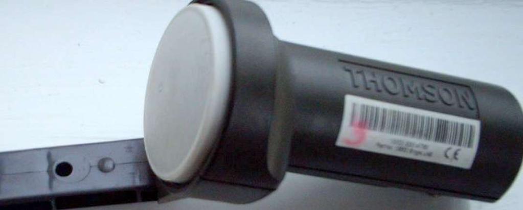
4 Analysis Examples: TV satellite LNB/dish/receiver system to explain. Movies: short movies about RF system and Antenna measurements.
 Voltage along line Transmission")
5 VSWR, Reflection Coefficient (r), Mismatched Loss (ML), and Return loss (RL) Voltage along line Transmission line
6


7 Network Analyzer د. محمد ألنظامي -- Nezami, Dr. Mohamed K.
8 Network Analyzer
9 The X-parameters
10
11 S-Parameters S-parameters measure the complex magnitude and phase relationship between small signals at the same frequency at different ports. Unlike S-parameters, X-parameters contain detailed and useful information including the magnitudes and phases of distortion products generated by the nonlinear component in response to large-signal conditions.
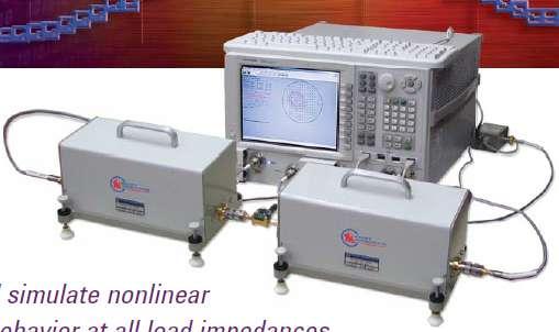
12 The X-parameters Generated from a circuit-level design in Advanced Design System (ADS) software. Measured using the Nonlinear Vector Network Analyzer. X-parameters can be easily imported into ADS and then dropped into a component or system to start the design process or for use with ADS linear, harmonic balance or circuit envelope simulation.
13 The X-parameters Created or Measured, X-parameters capture the frequency dependence and asymmetry of the intermodulations. X-parameters can be used to create a simulatable model for design with frequency-dependent distortion, like memory in PA. X-parameters allows you to measure and simulate nonlinear component behavior as a function of impedance, input power, bias and frequency at all load impedances.

14 Principle of S-parameters
15
16 Principle of S-parameters
17 Extracting Input/Output impedance from S-parameters
18


19 Network Analyzer SWR Network Analyzer method
20
21
22
23
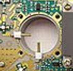
24 RF Impedance/ Material Analyzer


25 RF impedance/material analyzer This Equipment is used to characterize impedance or material at high frequency capacitance
26 RF impedance/material analyzer
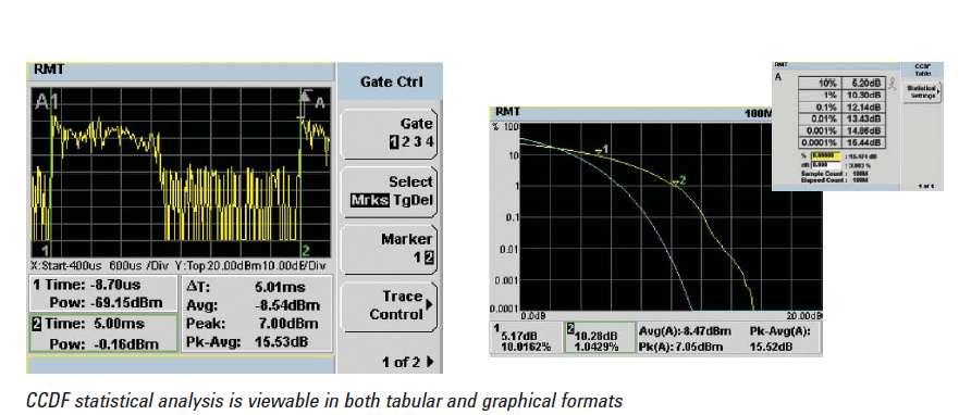
27 RF/Microwave Power Meter


28 RF Power Meter Power sensors, or Bolometers measures RF power by measuring the change in resistance due converting RF or microwave energy into heat within the bolometric element. Coaxial thermistor sensors

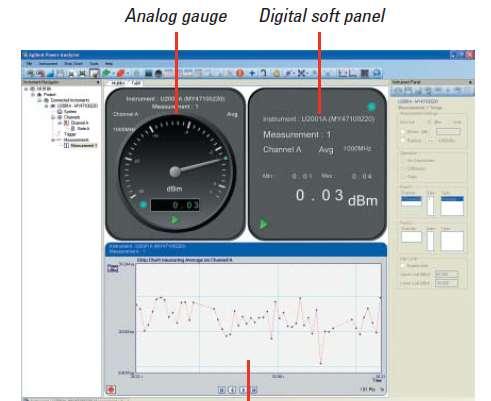
29 RF Power Meter

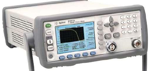
30 RF Power Meter
31 RF Power Meter Remotely monitoring transmitter output power
32 Time Domain Reflectometer (TDR)


33 Time Domain Reflectometer The TDR works on the same principle as radar. A pulse of energy is transmitted down a cable. When that pulse reaches the end of the cable, or a fault along the cable, part or all of the pulse energy is reflected back to the instrument
34 Time Domain Reflectometer Applications Characterize and locate faults in cables (twisted wire pairs, coaxial cables, and Microstrip). To locate discontinuities in a connectors, printed circuit board traces, or any other electrical path. To determine electrical length of lines. Determine cable unknown loads.

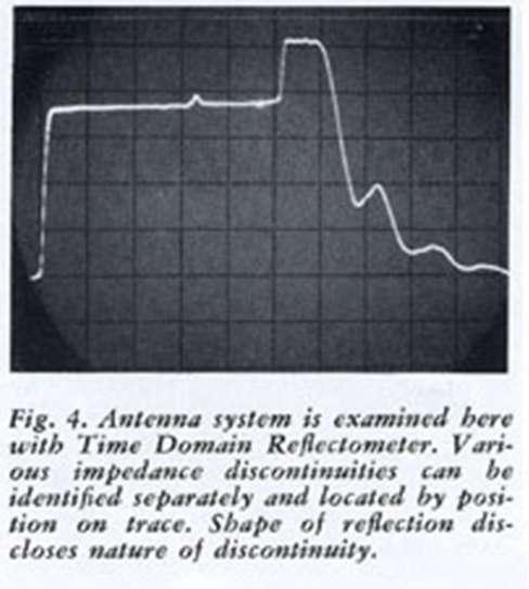
35 Time Domain Reflectometer Applications

36 Summary of Test Equipments

37 Summary of Test Equipments


38 RF/Microwave Connector Types BNC, TNC, N, UNF, Mini UHF, SMA, SMB, SMZ, F, MCX, MMCX, 1.5/5.6, FME, Twin axial, 1.0/2.3 DIN, 7/16 DIN
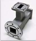
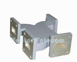
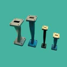
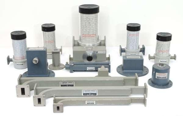
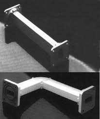
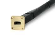
39 Waveguide Components

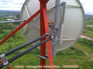

40 Antenna RF waveguide components
41 Measuring Antenna Parameters Input VSWR Input Impedance Radiation pattern Gain Beam-width Bandwidth Directivity Side Lope level Reciprocity
42
43 Measuring Antenna Input Parameters Input impedance for matching purposes Zin Return loss (S11) VSWR Efficiency
44 Measuring Antenna Transmission (Gain) Parameters
45
46 Antenna Measurements
47 Antenna Measurements

48 Antenna Measurements with the Network Analyzer S21 S11 The magnitude of the transfer function of an antenna system can be obtained by measuring the S21 parameter of the antenna using a network analyzer. Ideally this should be done in an anechoic chamber to provide accurate and repeatable results


49 Antenna Measurements with the Network Analyzer Network Analyzer

50 Antenna pattern measurement on transmit power and receiver sensitivity for notebooks, PCMCIA cards, and other terminals with WiMAX. The goal of the product certification process is to assure that WiMAX-enabled products perform as expected and provide the customer with a reliable communication experience. The RPT is one portion of this process that measures transmit power and receive sensitivity of WiMAX devices.
51 Principle of Gain Measurement using the Network Analyzer Connect Network Analyzer port 1 to any antenna with the same polarization as the AUT. Connect Network Analyzer port 2 to a calibrated reference a dipole Antenna with the same polarization as the AUT. Measure S21 (transmission coefficient of reference Antenna) with reference dipole antenna. P dbm) P ( dbm) G ( db) G ( db) PL( db) Replace the calibrated reference dipole with AUT, and measure S21 with AUT. P rx( tx tx _ Ant cal _ Ant rx ( dbm) Ptx( dbm) Gtx _ Ant ( db) GAUT _ The difference between the two S21 is the gain in dbd of your AUT Ant ( db) PL( db)
52 Gain Measurement using the Network Analyzer Dr. Mohamed K. Nezami, د. يماظنلأ دمحم -- كومريلأ ةعماج ) ( ) ( ) ( ) ( ) ( ) ( ) ( ) ( ) ( ) ( ) ( ) ( ) ( ) ( ) ( ) ( ) ( ) ( db G db G dbm P dbm P db G db G dbm P dbm P db PL db G db G dbm P dbm P db PL db G db G dbm P dbm P Ant AUT Ant cal AUT rx cal rx Ant AUT Ant cal AUT rx cal rx Ant AUT Ant tx tx AUT rx Ant cal Ant tx tx cal rx ) ( ) ( ) ( ) ( db G dbm P dbm P db G Ant cal cal rx AUT rx Ant AUT ant cal tx cal rx tx cal rx S dbm P dbm P watts P P _ 21 ) ( ) ( log 10 ant AUT tx AUT rx tx AUT rx S dbm P dbm P watts P P _ 21 ) ( ) ( log 10 ant AUT ant cal cal rx AUT rx S S dbm P dbm P _ _ ) ( ) ( ) ( ) ( db G S S db G Ant cal ant AUT ant cal Ant AUT
53 Gain Measurement using the Network Analyzer Example: S G G 21_ cal _ ant cal _ Ant AUT _ Ant S ( db) ( db) 21_ AUT _ ant 10dB 4dB 4dB 10( db) 6dB


54 Measurement using the Network Analyzer Beam and Band Width Side Lobe level Front-to-Back ratio Directivity
55 Travelling Wave Antennas Helical Antenna Yagi-Uda Antenna Dipole & Monopole Microstrip Antennas Microstrip Antennas Planar Antennas Reflector Antennas Corner Reflector Parabolic Reflector (Dish Antenna) Wire Antenna Aperture Antennas Slot Antenna Waveguide Antenna Horn Antenna Antenna Types
56 Horn Antennas Parabolic Antennas Satellite Antenna Wire Antenna Corner Reflector Antenna BiQuad Antenna Cubical Quad Antenna Cubical Quad Antenna Bow Tie Antenna Circular Polarization Antennas Tactical Antennas Aircraft Antenna Cellular & WLAN Antennas Helical Antenna Yagi-Antenna Loop Antenna Log-Periodic Antennas Vertical/Horizontal Stacking of Antennas Printed Antennas (Microstrip Antennas) RFID (wire loop) Antenna Satellite TV Reception Example Fun Free Antenna Designs References
57 Monopole and Dipole Antennas


58 Dipole & Monopole 4 2 GND radials b) Monopole


59 Half Wave Dipole Antenna 4 Construction 4 4 4
60 Characteristics of Dipoles and Monopoles A ½ λ dipole has an impedance of about 73 Ω. Vee A ½ λ dipole has a gain of 3dBi Monopole and Dipole are omnidirectional (in azimuth, or horizontal). Monopole has a gain of 1.64 (or G = 2.15 dbi) Loop A 1/4 λ Monopole has an impedance of about 73/2=36 Ω. A ½ λ folded dipole has an input impedance of about 300 Ω. A ½ λ folded dipole is used as the driving element in many other types of antennas. Loop fed Yagi 300/75 Ohm Balun
61 Characteristics of Dipoles and Monopoles Most TV receivers are equipped with two indoor antennas, one to cover the VHF band and the other the UHF band. The most common VHF antennas are the extendible monopole and vee dipole colloquially known as the rabbit ears. Rabbit ears (Vee) Antenna is available with either a 75 Ω or 300 Ω impedance and has a typical gain of -4 db with respect to a ½ λ dipole. The common UHF antennas are the circular loop with impedance of 300 Ω.

62 Marconi Monopole Antenna Construction Radially-dispersed wire radial system to enhance the ground conductivity
 The input impedance is half the dipole input impedance, 36Ohms.")
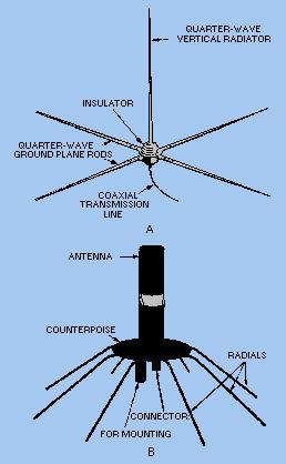
63 Quarter Wave Ground Plane ( Ground elements are bent 30 to 45 degrees down. This set of elements, called radials, is known as a ground plane. If used as car antenna, car body serves as ground plane. The gain is in the order of 2-4 dbi. Marconi Antenna) The input impedance is half the dipole input impedance, 36Ohms. This is a simple and effective antenna that can capture a signal equally from all directions (Omni in horizontal plane). When used in cellular telephones, the metal back plate of the phone serves as the ground plane.
64 Radiation pattern of Dipoles and Monopoles The azimuthal pattern of Dipole is a circle. The azimuthal pattern of is a circle.


65 Radiation pattern of Dipoles and Monopoles


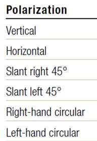
66 Antenna Polarization The polarization of an antenna is determined by the orientation of the the electrical component of the wave.


67 Antenna Polarization Vertical Vertical Vertical Horizontal
68
69 Shortening Monopole Antennas

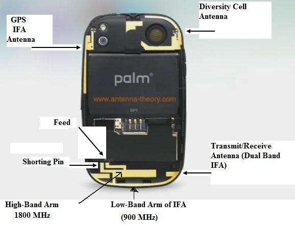
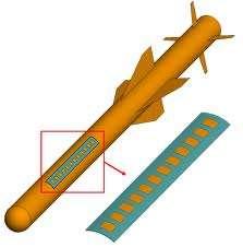
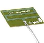
70 Multi-Band Monopole Antennas
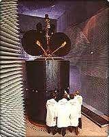
71 Horn Antennas


72 A horn antenna or microwave horn is an antenna that consists of a flaring metal waveguide shaped like a horn to direct the radio waves. Horn antennas are commonly used as the active element in a dish antenna..
73 Horn Configurations This horn antenna is flared in the E-plane This horn is flared in the H-plane Most popular Pyramid Horn is flared in both planes


74 Horn RF Signal Coupling Single polarization feed Dual polarization feed
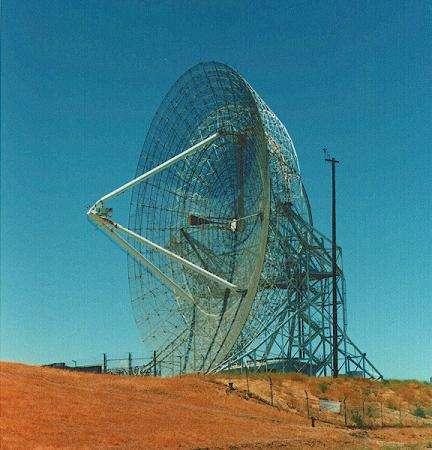
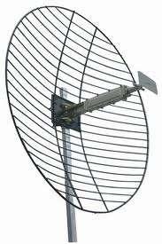
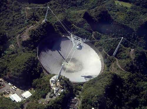
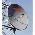
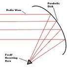
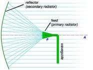
75 Parabolic Antennas
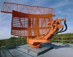

76

77
78
79 n is the efficiency or the effectiveness of illumination of the dish by the feed

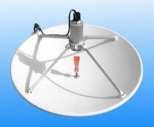
80 Dual offset feed
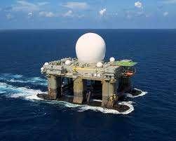
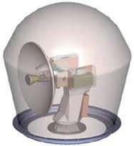
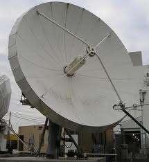
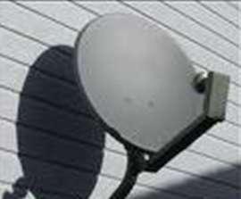
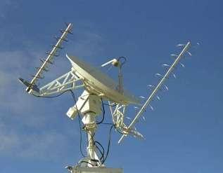
81 Satellite Antenna

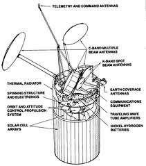
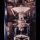
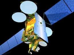
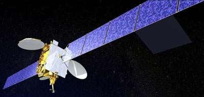
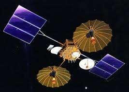
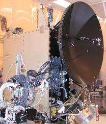
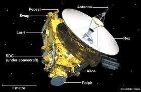
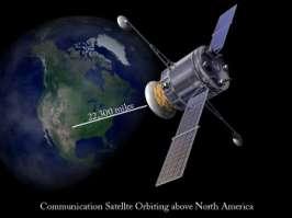
82 Satellite Antenna
83 Wire Antenna


84 Wire Antenna the feedpoint impedance is about Mhz full-wave loop is 100-ohms, so a 2:1 matching transformer is required when using 50 coax
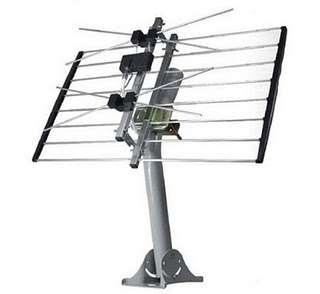
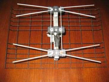
85 Corner Reflector Antenna


86 Corner reflector antenna comprised of one or more dipole elements in front of a corner reflector.
87
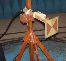
88 BiQuad Antenna


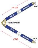
89 BiQuad Antenna simple to build and offers good directivity and gain for Point-to-Point communications a beamwidth of about 70 degrees gain in the order of dbi sed as stand-alone antenna or as feeder for a Parabolic Dish
90

91 D is the Distance from the Dipole to the Reflector Dr. Mohamed K. Nezami, -- د. محمد ألنظامي
92 Cubical Quad Antenna


93 A quad loop is a pair of dipole antennas mounted one above the other A quad fed at the bottom is horizontally polarized and this is usual on the HF bands. Fed at the side the quad will be vertically polarized.
94 Bow Tie Antenna

95 Bow Tie Antenna
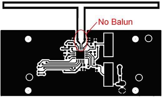
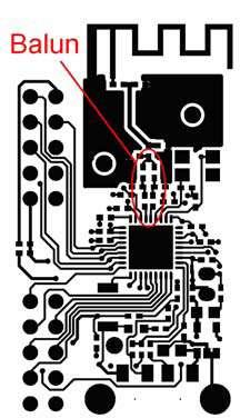
96 The side of the bowtie-triangle is a quarter-wavelength to the lowest frequency of interest. So technically, quarter-wave plus quarter-wave will make it a half-wavelength dipole, For example, for freq. = Mhz (ch 7), half wave = " The broader the angle, the broader the bandwidth. 60 to 90 degrees are common. It needs a BALANCED transmission line or a coax cable with a BALUN just like a normal dipole. BOW TIE has a OHM impedance this requires a 4:1 current balun for the un-balanced (50 OHM coax) feedline. BOW TIE provides a 3 db gain over a simple dipole If the antenna is mounted ¼ λ in front of a reflecting surface, the gain increases to approximately 9 db. Stacking two of them vertically one wavelength apart, increases the overall gain to about 12 db

97 Vertical Stacking

98 Vertical Stacking
99 Circular Polarization Antennas
100
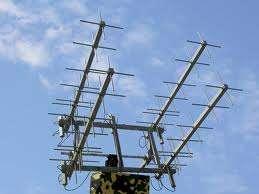
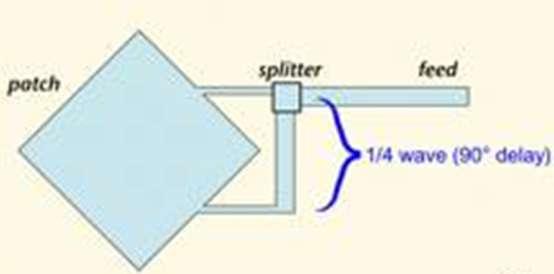
101
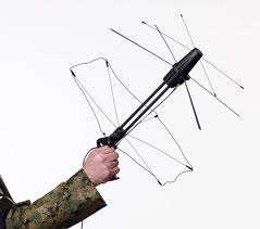
102 Tactical Antennas

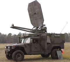
103
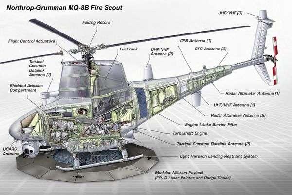
104 Aircraft Antenna

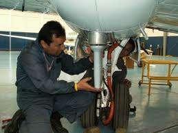
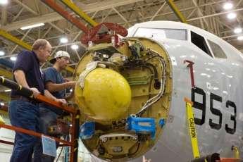


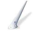

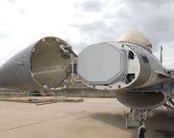
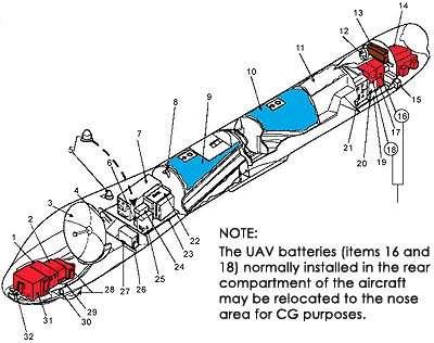
105 Aircraft Antenna
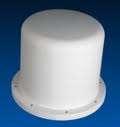
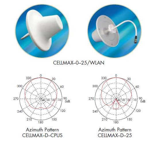
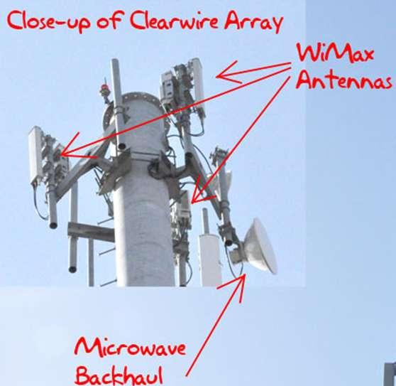
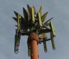
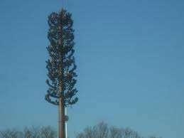
106 Cellular & WLAN Antennas


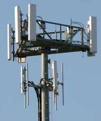
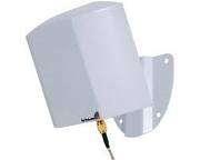
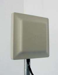
107 Panel antennas Tilting Sectoring


108 Panel antennas are made up of several dipoles mounted in front of a reflector so that gain can be achieved from both the horizontal and vertical plane.
109
110
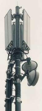
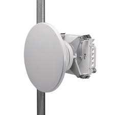
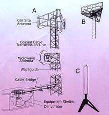
111 Backhauling Microwave Link Antennas
112 POLARIZATION DIVERSITY SPACE DIVERSITY
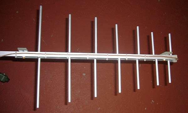
113 Polarization Diversity Space diversity uses 2 vertically polarized antennas as reception antennas and compares the signal level. Polarization diversity uses 2 orthogonally polarized antennas and compares the resulting signals. mobile telephone is never held exactly upright which means that all polarizations between vertical and horizontal are possible Dr. Mohamed K. Nezami, د. محمد ألنظامي --
114 If in addition the vertical path of the dual polarized antenna is fed via a duplexer for Rx and Tx, then only one antenna is needed per sector. As a result all 3 sectors can be supplied from one mast
115 Sector antenna system using Space Diversity Reception - 3 antennas, 3 feeders 3 to 5 db, Sector antenna system with Polarization Diversity Reception - 2 antennas, 3 feeders Sector antenna system with Polarization Diversity Reception using a duplex filter1 antenna, 3 feeders, 1 duplexer


116
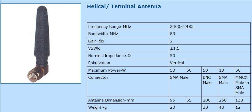
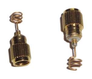
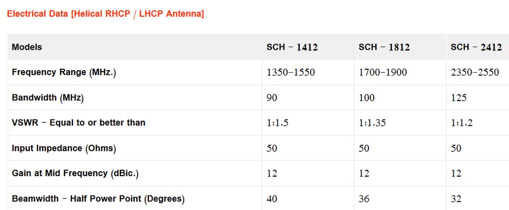
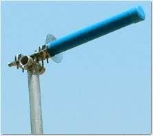
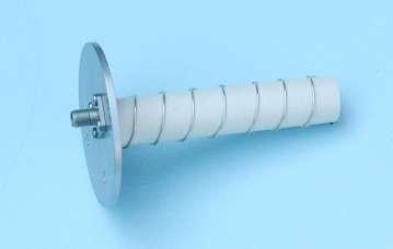
117 Helical Antenna


118 wide bandwidth easily constructed circularly polarized impedance is approximately 125 ohms so a matching transformer is required. The antenna is quite broadbanded. Beam widths of 50 Dr. and Mohamed a gain K. Nezami, of 12 dbi -- or greater are easily attained د. محمد ألنظامي

119 Online Helix Antenna Designer

120
121
122 Yagi-Antenna

 than half wavelength; a director is placed in front of the driven element and is slightly shorter")

123 It can be constructed with one or more (usually one or two) reflector elements and one or more (usually two or more) director elements. approximately 0.2 to 0.5 wavelength on either side of it, are straight rods or wires called reflectors and directors A reflector is placed behind the driven element and is slightly longer (+5%) than half wavelength; a director is placed in front of the driven element and is slightly shorter (-5%)than half wavelength It consists of a half wave dipole (sometimes a folded one, sometimes not), a rear "reflector" and may or may not have one or more forward "directors". Yagi antennas are used primarily for Point-to- Point links, have a gain from 10 to 20 dbi and a horizontal beamwidth of 10 to 20 degrees. can be mounted to support either horizontal or vertical polarization
124 The antenna gain is a function of the number of dipole elements : GT = 1.66 * N where N is the number of elements in the Yagi antenna Maximum gain will be about 5.5 dbi for a two element Yagi to 10.5 dbi for five elements
125 Loop Antenna


126 Folded Dipole Full wave feedpoint impedance of 300 ohms half wave dipole is 75 ohms that the upper half wavelength dipole is voltage fed from the ends of the lower dipole; this is not a parasitic element broader bandwidth than a wire dipole VHF/UHF region. Folded dipole antennas were mainly used in conjuction with Yagi antennas.
127 The Loop Antenna directivity is about 3.5 db. The mid band gain is 3 db higher than a ½ λ dipole, but falls off to about 1 db at either end The dipole is typically 0.45 to 0.49 wavelengths long. The reflector is normally 0.55 wavelengths long and placed anywhere from 0.1 to 0.25 wavelengths behind the dipole. The reflector spacing has no affect on the forward gain, but does influence the front to back ratio and input impedance. The directors are normally 0.4 to 0.45 wavelengths long and are spaced at 0.3 to 0.4 wavelengths in front of the dipole. An antenna will usually have 6 to 12 directors.
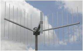
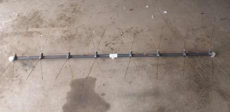
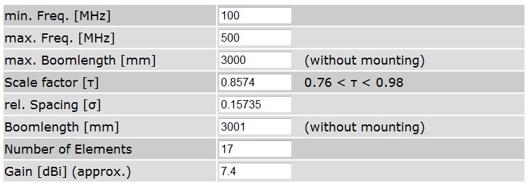
128 Log-Periodic Antennas


129 Log-Periodic Antenna is comprised of a set of dipoles, all active, that vary in size from smallest at the front to largest at the rear. Broadband, and its front-to-back gain ratio is high.
130
131 Vertical/Horizontal Stacking of Antennas


132 By connecting single, and vertically stacked dipoles at a middle distance of one wavelength the half power beamwidth can be reduced. As a result the horizontal gain is increased. Each doubling of the number of dipoles results in a gain increase of 3 db. Vertical Dipole Stacking

133 Vertical Dipole Stacking
134
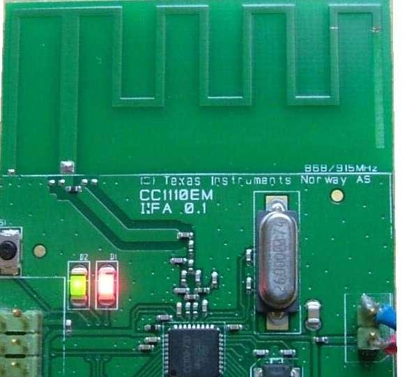
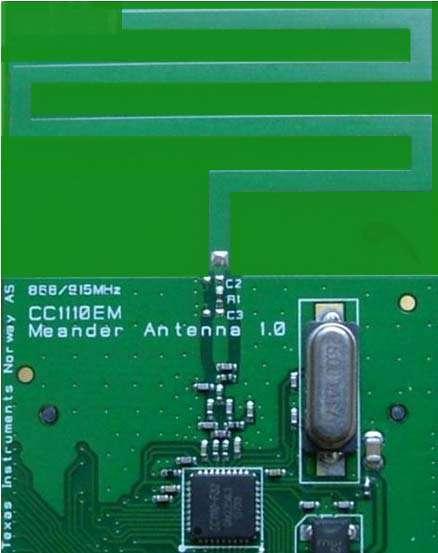
135 Printed Antennas (Microstrip Antennas)


136


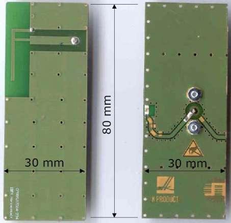
137 inverted F antenna [5], [6] is similar to a freestanding quarter-wave monopole above a ground plane

138 The positions of the two conductors determine the impedance and bandwidth as well as the field pattern. Inverted-L antenna Inverted-F antenna


139 The vertical arm is a stub tuning device to tune out the capacitance of the cross arm The cross arm is a quarter wavelength the configuration is treated as a small loop inductor, consisting of the feed probe and the inverted-l element behind the feed, resonated with the capacitance of a horizontal wire above a ground plane. The addition of the extra inverted-l element behind the feed tunes the input impedance of the antenna. [4] The -- ألنظامي impedance د. محمد is adjusted by changing جامعة point. أليرموكtap the Dr. Mohamed K. Nezami,
140
141
142

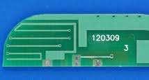
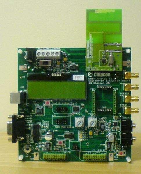
143 approximately 7dBi gain. Impedance of the antenna input is 50 Ω 2.4 GHz Yagi PCB Directional Antenna Test Board
144


145 PCB Material: FR4 PWB Thickness: 15 mils Red represents vertical polarization and blue represents horizontal polarization both measured in dbi
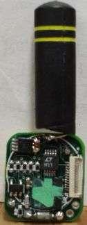
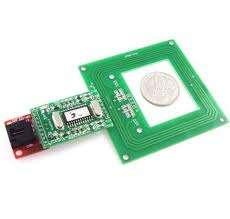
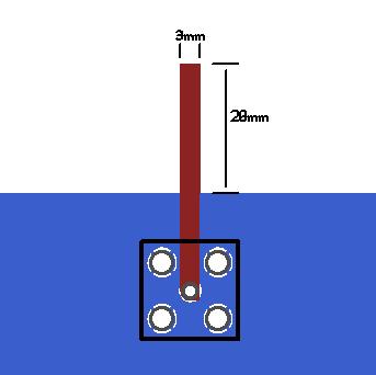
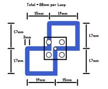
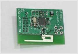
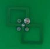
146 RFID (wire loop) Antenna


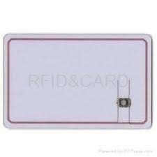
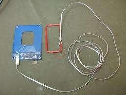
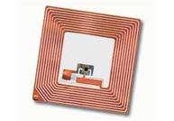

147 RFID (wire loop) Antenna
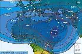
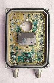
148 Satellite TV Reception Example

149 BADR Ku BAND SIGNALS

150 Diseq switch


151 Low Band: 10.7GHz to 11.7GHz High Band: 11.7GHz-12.7GHz IF:.95GHz-2.15GHz
 is generated by the satellite receiver to switch the target LNB between H/V polarizations, and between the low and high bands received (22 khz absent/present).")
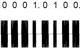
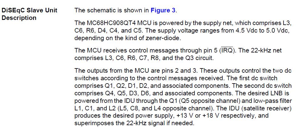
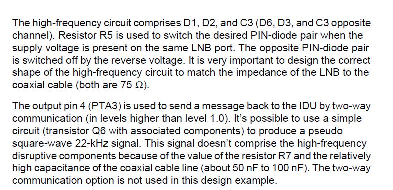
152 IF_Low=10.7GHz-9.75GHz=0.95Ghz IF_High=11.7GHz-9.75GHz=1.95Gh IF_Low=11.7GHz-10.6GHz=1.1Ghz IF_High=12.75GHz-10.6GHz=2.15Ghz Digital Satellite Equipment Control (DiSEqCä ). The signal (voltage and 22-kHz tone) is generated by the satellite receiver to switch the target LNB between H/V polarizations, and between the low and high bands received (22 khz absent/present). The DSU is through-hold for this signal.
153
 http://www.eutelsat.")
154 A OUT B 22 khz amplitude-modulated signaling)


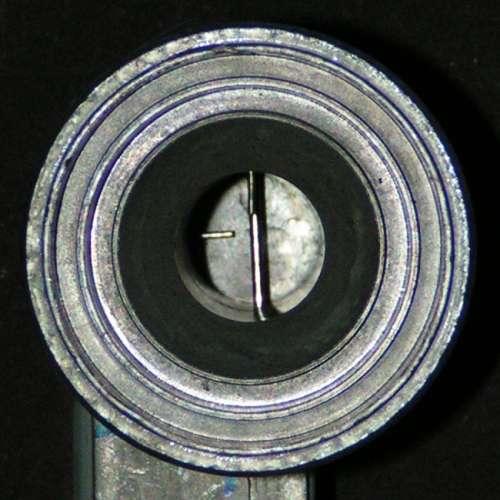
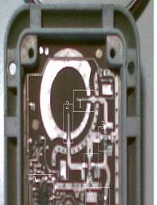
155 Dual Horn Fed Parabolic Dish
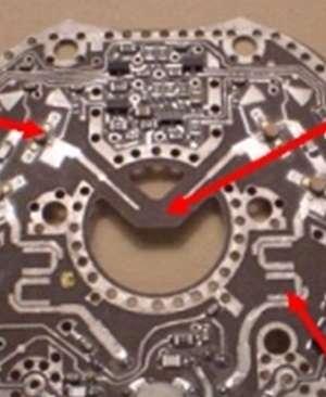
156 LNB Voltage Regulators zener diode
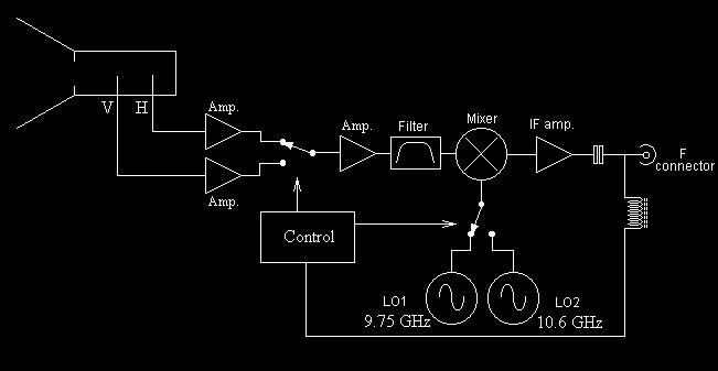
157 High/Low Local Oscillator frequency, Horizontal/Vertical polarization and two satellite locations. SAT-A/SAT-B Polarization Horz/Ver Local Oscillator High /Low
158
159

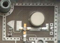
160 Image Rejection BPF Filter
161


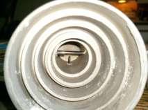
162 IF-AMP IMAGE FIL DRO Vertical IF-AMP Horizontal

163 Vertical MIXER/IFAMP RF-IN Horiz DRO BPF Inter-digital filter

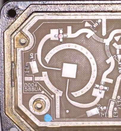
164 Hair Pin filter

165 Edge coupled filter

166 DRO MIXER BPF IF-AMP Hair Pin filter


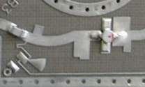
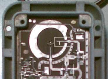
167 The radial stub has wider bandwidth and therefore less manufacturing tolerance problems. The disadvantage is the board surface area it takes up

168 Hair Pin filter BPF DRO Horiz RF-IN Vertical MIXER/IFAMP

169 Hair Pin filter

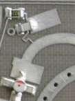
170 Edge coupled filter Mixer

171 Microwave Mixer Implementation
172

173 Edge coupled filter


174 Image filter response: Grundig AUN3S Inter-digital filter

175 Hair Pin filter
176 Fun Free Antenna Designs
177


178
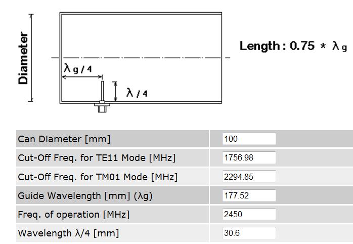
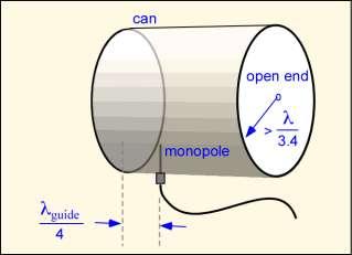
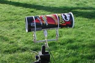
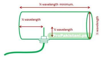
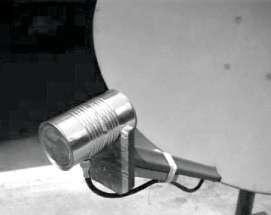
179 Cantenna
180 References

181 1. C.A. Balanis,.Antenna Theory: Analysis and Design., third edition, John Wiley & Sons, 2005, pp R.C. Johnson and H. Jasik,.Antenna Engineering Handbook., second edition, McGraw-Hill Book Company, ?metc=mtsz3m
Chapter 6 Antenna Basics. Dipoles, Ground-planes, and Wires Directional Antennas Feed Lines
 Chapter 6 Antenna Basics Dipoles, Ground-planes, and Wires Directional Antennas Feed Lines Some General Rules Bigger is better. (Most of the time) Higher is better. (Most of the time) Lower SWR is better.
Half-Wave Dipole. Radiation Resistance. Antenna Efficiency
 Antennas Simple Antennas Isotropic radiator is the simplest antenna mathematically Radiates all the power supplied to it, equally in all directions Theoretical only, can t be built Useful as a reference:
General License Class Chapter 6 - Antennas. Bob KA9BHD Eric K9VIC
 General License Class Chapter 6 - Antennas Bob KA9BHD Eric K9VIC Learning Objectives Teach you enough to get all the antenna questions right during the VE Session Learn a few things from you about antennas
Dr. John S. Seybold. November 9, IEEE Melbourne COM/SP AP/MTT Chapters
 Antennas Dr. John S. Seybold November 9, 004 IEEE Melbourne COM/SP AP/MTT Chapters Introduction The antenna is the air interface of a communication system An antenna is an electrical conductor or system
4/29/2012. General Class Element 3 Course Presentation. Ant Antennas as. Subelement G9. 4 Exam Questions, 4 Groups
 General Class Element 3 Course Presentation ti ELEMENT 3 SUB ELEMENTS General Licensing Class Subelement G9 Antennas and Feedlines 4 Exam Questions, 4 Groups G1 Commission s Rules G2 Operating Procedures
EMG4066:Antennas and Propagation Exp 1:ANTENNAS MMU:FOE. To study the radiation pattern characteristics of various types of antennas.
 OBJECTIVES To study the radiation pattern characteristics of various types of antennas. APPARATUS Microwave Source Rotating Antenna Platform Measurement Interface Transmitting Horn Antenna Dipole and Yagi
CHAPTER 8 ANTENNAS 1
 CHAPTER 8 ANTENNAS 1 2 Antennas A good antenna works A bad antenna is a waste of time & money Antenna systems can be very inexpensive and simple They can also be very expensive 3 Antenna Considerations
4 Antennas as an essential part of any radio station
 4 Antennas as an essential part of any radio station 4.1 Choosing an antenna Communicators quickly learn two antenna truths: Any antenna is better than no antenna. Time, effort and money invested in the
ANTENNAS. I will mostly be talking about transmission. Keep in mind though, whatever is said about transmission is true of reception.
 Reading 37 Ron Bertrand VK2DQ http://www.radioelectronicschool.com ANTENNAS The purpose of an antenna is to receive and/or transmit electromagnetic radiation. When the antenna is not connected directly
Antenna Trainer EAN. Technical Teaching Equipment INTRODUCTION
 Antenna Trainer EAN Technical Teaching Equipment Products Products range Units 3.-Communications INTRODUCTION Antennas are the main element of aerial communications. They are the transition between a transmission
Practical Antennas and. Tuesday, March 4, 14
 Practical Antennas and Transmission Lines Goals Antennas are the interface between guided waves (from a cable) and unguided waves (in space). To understand the various properties of antennas, so as to
Antenna Training and Measuring System
 Antenna Training and Measuring System LabVolt Series Datasheet Festo Didactic en 120 V - 60 Hz 05/2018 Table of Contents General Description 2 Antennas 5 Features & Benefits 7 List of Equipment 8 List
Development of a noval Switched Beam Antenna for Communications
 Master Thesis Presentation Development of a noval Switched Beam Antenna for Communications By Ashraf Abuelhaija Supervised by Prof. Dr.-Ing. Klaus Solbach Institute of Microwave and RF Technology Department
CHAPTER 5 PRINTED FLARED DIPOLE ANTENNA
 CHAPTER 5 PRINTED FLARED DIPOLE ANTENNA 5.1 INTRODUCTION This chapter deals with the design of L-band printed dipole antenna (operating frequency of 1060 MHz). A study is carried out to obtain 40 % impedance
Amateur Radio License. Propagation and Antennas
 Amateur Radio License Propagation and Antennas Todays Topics Propagation Antennas Propagation Modes Ground wave Low HF and below, ground acts as waveguide Line-of-Sight (LOS) VHF and above, radio waves
Traveling Wave Antennas
 Traveling Wave Antennas Antennas with open-ended wires where the current must go to zero (dipoles, monopoles, etc.) can be characterized as standing wave antennas or resonant antennas. The current on these
Antennas Demystified Antennas in Emergency Communications. Scott Honaker N7SS
 Antennas Demystified Antennas in Emergency Communications Scott Honaker N7SS Importance of Antennas Antennas are more important than the radio A $5000 TV with rabbit ears will have a lousy picture Antennas
UNIVERSITI MALAYSIA PERLIS
 UNIVERSITI MALAYSIA PERLIS SCHOOL OF COMPUTER & COMMUNICATIONS ENGINEERING EKT 341 LABORATORY MODULE LAB 2 Antenna Characteristic 1 Measurement of Radiation Pattern, Gain, VSWR, input impedance and reflection
Resonant Antennas: Wires and Patches
 Resonant Antennas: Wires and Patches Dipole Antennas Antenna 48 Current distribution approximation Un-normalized pattern: and Antenna 49 Radiating power: For half-wave dipole and,, or at exact resonance.
Antenna Fundamentals. Microwave Engineering EE 172. Dr. Ray Kwok
 Antenna Fundamentals Microwave Engineering EE 172 Dr. Ray Kwok Reference Antenna Theory and Design Warran Stutzman, Gary Thiele, Wiley & Sons (1981) Microstrip Antennas Bahl & Bhartia, Artech House (1980)
Technician Licensing Class T9
 Technician Licensing Class T9 Amateur Radio Course Monroe EMS Building Monroe, Utah January 11/18, 2014 January 22, 2014 Testing Session Valid dates: July 1, 2010 June 30, 2014 Amateur Radio Technician
Newsletter 2.3. Antenna Magus version 2.3 released! New antennas in Version 2.3. Potter horn. Circularly polarised rectangular-biquad antenna
 Newsletter 2.3 October 2010 Antenna Magus version 2.3 released! An update to Antenna Magus, version 2.3, is now available for download. This update features 10 new antennas, as opposed to the usual 6.
Broadband Antenna. Broadband Antenna. Chapter 4
 1 Chapter 4 Learning Outcome At the end of this chapter student should able to: To design and evaluate various antenna to meet application requirements for Loops antenna Helix antenna Yagi Uda antenna
Chapter 6 Broadband Antenna. 1. Loops antenna 2. Heliksantenna 3. Yagi uda antenna
 Chapter 6 Broadband Antenna 1. Loops antenna 2. Heliksantenna 3. Yagi uda antenna 1 Design A broadband antenna should have acceptable performance (determined by its pattern, gain and/or feed-point impedance)
Range Considerations for RF Networks
 TI Technology Days 2010 Range Considerations for RF Networks Richard Wallace Abstract The antenna can be one of the most daunting components of wireless designs. Most information available relates to large
Antennas and Propagation Chapters T4, G7, G8 Antenna Fundamentals, More Antenna Types, Feed lines and Measurements, Propagation
 Antennas and Propagation Chapters T4, G7, G8 Antenna Fundamentals, More Antenna Types, Feed lines and Measurements, Propagation =============================================================== Antenna Fundamentals
Antenna Fundamentals Basics antenna theory and concepts
 Antenna Fundamentals Basics antenna theory and concepts M. Haridim Brno University of Technology, Brno February 2017 1 Topics What is antenna Antenna types Antenna parameters: radiation pattern, directivity,
Antennas & Transmission Lines
 Antennas & Transmission Lines Network Startup Resource Center www.nsrc.org These materials are licensed under the Creative Commons Attribution-NonCommercial 4.0 International license (http://creativecommons.org/licenses/by-nc/4.0/)
Milton Keynes Amateur Radio Society (MKARS)
") Milton Keynes Amateur Radio Society (MKARS) Intermediate Licence Course Feeders Antennas Matching (Worksheets 31, 32 & 33) MKARS Intermediate Licence Course - Worksheet 31 32 33 Antennas Feeders Matching
Milton Keynes Amateur Radio Society (MKARS) Intermediate Licence Course Feeders Antennas Matching (Worksheets 31, 32 & 33) MKARS Intermediate Licence Course - Worksheet 31 32 33 Antennas Feeders Matching
MICROWAVE MICROWAVE TRAINING BENCH COMPONENT SPECIFICATIONS:
 Microwave section consists of Basic Microwave Training Bench, Advance Microwave Training Bench and Microwave Communication Training System. Microwave Training System is used to study all the concepts of
SI TECHNICAL 2018 UNIT IV QUESTION BANK
 SI TECHNICAL 2018 UNIT IV QUESTION BANK 1. In what range of frequencies are most omnidirectional horizontally polarized antennas used? A. VHF, UHF B. VLF, LF C. SH, EHF D. MF, HF 2. If the current ratios
CHAPTER 5 THEORY AND TYPES OF ANTENNAS. 5.1 Introduction
 CHAPTER 5 THEORY AND TYPES OF ANTENNAS 5.1 Introduction Antenna is an integral part of wireless communication systems, considered as an interface between transmission line and free space [16]. Antenna
ANTENNA AND TRANSMISSION LINE
 ANTENNA AND TRANSMISSION LINE series allows students to perform experiments to learn all concepts, equipment and systems used in modern transmission systems. This series analyzes all technologies and systems
Chapter 5.0 Antennas Section 5.1 Theory & Principles
 Chapter 5.0 Antennas Section 5.1 Theory & Principles G3C11 (B) p.135 Which of the following antenna types will be most effective for skip communications on 40-meters during the day? A. A vertical antenna
4/25/2012. Supplement T9. 2 Exam Questions, 2 Groups. Amateur Radio Technician Class T9A: T9A: T9A: T9A:
 Amateur Radio Technician Class Element 2 Course Presentation ti ELEMENT 2 SUB-ELEMENTS Technician Licensing Class Supplement T9 Antennas, Feedlines 2 Exam Questions, 2 Groups T1 - FCC Rules, descriptions
Cray Valley Radio Society. Real Life Wire Antennas
 Cray Valley Radio Society Real Life Wire Antennas 1 The basic dipole The size of an antenna is determined by the wavelength of operation In free space: ~3x10 8 m/s Frequency x Wavelength = Speed of Light,
Technician Licensing Class. Lesson 4. presented by the Arlington Radio Public Service Club Arlington County, Virginia
 Technician Licensing Class Lesson 4 presented by the Arlington Radio Public Service Club Arlington County, Virginia 1 Quiz Sub elements T6 & T7 2 Good Engineering Practice Sub element T8 3 A Basic Station
Antennas Prof. Girish Kumar Department of Electrical Engineering Indian Institute of Technology, Bombay. Module 2 Lecture - 10 Dipole Antennas-III
 Antennas Prof. Girish Kumar Department of Electrical Engineering Indian Institute of Technology, Bombay Module 2 Lecture - 10 Dipole Antennas-III Hello, and welcome to todays lecture on Dipole Antenna.
Technician Licensing Class. Antennas
 Technician Licensing Class Antennas Antennas A simple dipole mounted so the conductor is parallel to the Earth's surface is a horizontally polarized antenna. T9A3 Polarization is referenced to the Earth
Travelling Wave, Broadband, and Frequency Independent Antennas. EE-4382/ Antenna Engineering
 Travelling Wave, Broadband, and Frequency Independent Antennas EE-4382/5306 - Antenna Engineering Outline Traveling Wave Antennas Introduction Traveling Wave Antennas: Long Wire, V Antenna, Rhombic Antenna
Fundamentals of Antennas. Prof. Ely Levine
 Fundamentals of Antennas Prof. Ely Levine levineel@zahav.net.il 1 Chapter 3 Wire Antennas 2 Types of Antennas 3 Isotropic Antenna Isotropic radiator is the simplest antenna mathematically Radiates all
Antenna Technology Bootcamp. NTA Show 2017 Denver, CO
 Antenna Technology Bootcamp NTA Show 2017 Denver, CO Review: How a slot antenna works The slot antenna is a TEM-Mode coaxial structure. Coupling structures inside the pylon will distort and couple to the
Antennas 101 Don t Be a 0.97 db Weakling! Ward Silver NØAX
 Antennas 101 Don t Be a 0.97 db Weakling! Ward Silver NØAX Overview Antennas 101 2 Overview Basic Antennas: Ground Plane / Dipole How Gain and Nulls are Formed How Phased Arrays Work How Yagis Work (simplified)
Antenna Theory and Design
 Antenna Theory and Design Antenna Theory and Design Associate Professor: WANG Junjun 王珺珺 School of Electronic and Information Engineering, Beihang University F1025, New Main Building wangjunjun@buaa.edu.cn
Novel Broadband and Multi-band Antennas for Satellite and Wireless Applications
 Novel Broadband and Multi-band Antennas for Satellite and Wireless Applications The objective of our research is to develop novel antenna structures for broadband and/or multi-band satellite and wireless
I J E E Volume 5 Number 1 January-June 2013 pp
 I J E E Volume 5 Number 1 January-June 2013 pp. 21-25 Serials Publications, ISSN : 0973-7383 Various Antennas and Its Applications in Wireless Domain: A Review Paper P.A. Ambresh 1, P.M. Hadalgi 2 and
Improved Ionospheric Propagation With Polarization Diversity, Using A Dual Feedpoint Cubical Quad Loop
 Improved Ionospheric Propagation With Polarization Diversity, Using A Dual Feedpoint Cubical Quad Loop by George Pritchard - AB2KC ab2kc@optonline.net Introduction This Quad antenna project covers a practical
Technician License. Course
 Technician License Course Technician License Course Chapter 4 Lesson Plan Module - 10 Practical Antennas The Dipole Most basic antenna The Dipole Most basic antenna The Dipole Total length is ½ wavelength
The Basics of Patch Antennas, Updated
 The Basics of Patch Antennas, Updated By D. Orban and G.J.K. Moernaut, Orban Microwave Products www.orbanmicrowave.com Introduction This article introduces the basic concepts of patch antennas. We use
Broadband Circular Polarized Antenna Loaded with AMC Structure
 Progress In Electromagnetics Research Letters, Vol. 76, 113 119, 2018 Broadband Circular Polarized Antenna Loaded with AMC Structure Yi Ren, Xiaofei Guo *,andchaoyili Abstract In this paper, a novel broadband
Microstrip Antennas Integrated with Horn Antennas
 53 Microstrip Antennas Integrated with Horn Antennas Girish Kumar *1, K. P. Ray 2 and Amit A. Deshmukh 1 1. Department of Electrical Engineering, I.I.T. Bombay, Powai, Mumbai 400 076, India Phone: 91 22
Notes 21 Introduction to Antennas
 ECE 3317 Applied Electromagnetic Waves Prof. David R. Jackson Fall 018 Notes 1 Introduction to Antennas 1 Introduction to Antennas Antennas An antenna is a device that is used to transmit and/or receive
UNIVERSITY OF UTAH ELECTRICAL AND COMPUTER ENGINEERING DEPARTMENT. ECE 5324/6324 ANTENNA THEORY AND DESIGN Spring 2013
 UNIVERSITY OF UTAH ELECTRICAL AND COMPUTER ENGINEERING DEPARTMENT ECE 5324/6324 ANTENNA THEORY AND DESIGN Spring 2013 Instructor: O. P. Gandhi Office: MEB 4508 1. This is an engineering course which deals
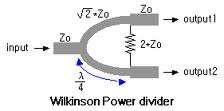
You will need the following pieces of equipment to complete this experiment: Wilkinson power divider (3-port board with oval-shaped trace on it)
") UNIVERSITY OF TORONTO FACULTY OF APPLIED SCIENCE AND ENGINEERING The Edward S. Rogers Sr. Department of Electrical and Computer Engineering ECE422H1S: RADIO AND MICROWAVE WIRELESS SYSTEMS EXPERIMENT 1:
UNIVERSITY OF TORONTO FACULTY OF APPLIED SCIENCE AND ENGINEERING The Edward S. Rogers Sr. Department of Electrical and Computer Engineering ECE422H1S: RADIO AND MICROWAVE WIRELESS SYSTEMS EXPERIMENT 1:
Antennas Prof. Girish Kumar Department of Electrical Engineering India Institute of Technology, Bombay. Module - 1 Lecture - 1 Antennas Introduction-I
 Antennas Prof. Girish Kumar Department of Electrical Engineering India Institute of Technology, Bombay Module - 1 Lecture - 1 Antennas Introduction-I Hello everyone. Welcome to the exciting world of antennas.
Newsletter 5.4. New Antennas. The profiled horns. Antenna Magus Version 5.4 released! May 2015
 Newsletter 5.4 May 215 Antenna Magus Version 5.4 released! Version 5.4 sees the release of eleven new antennas (taking the total number of antennas to 277) as well as a number of new features, improvements
Conclusion and Future Scope
 Chapter 8 8.1 Conclusions The study of planar Monopole, Slot, Defected Ground, and Fractal antennas has been carried out to achieve the research objectives. These UWB antenna designs are characterised
Chapter 2. Modified Rectangular Patch Antenna with Truncated Corners. 2.1 Introduction of rectangular microstrip antenna
 Chapter 2 Modified Rectangular Patch Antenna with Truncated Corners 2.1 Introduction of rectangular microstrip antenna 2.2 Design and analysis of rectangular microstrip patch antenna 2.3 Design of modified
ANTENNA THEORY. Analysis and Design. CONSTANTINE A. BALANIS Arizona State University. JOHN WILEY & SONS New York Chichester Brisbane Toronto Singapore
 ANTENNA THEORY Analysis and Design CONSTANTINE A. BALANIS Arizona State University JOHN WILEY & SONS New York Chichester Brisbane Toronto Singapore Contents Preface xv Chapter 1 Antennas 1 1.1 Introduction
Antenna. Wave length Km/s
 Antenna 5% Wave length 300 000 Km/s 066 velocity factor RG-58 = C = = F : 120 Impedance 50 50 50 VSWR and Reflected Power SWR VSWR VSWR 2:1 Voltage Standing Wave Ratio VSWR 15:1 15:1 VSWR 100 Watt 1:1
RADIATION PATTERNS. The half-power (-3 db) beamwidth is a measure of the directivity of the antenna.
 beamwidth is a measure of the directivity of the antenna.") RADIATION PATTERNS The radiation pattern is a graphical depiction of the relative field strength transmitted from or received by the antenna. Antenna radiation patterns are taken at one frequency, one
RADIATION PATTERNS The radiation pattern is a graphical depiction of the relative field strength transmitted from or received by the antenna. Antenna radiation patterns are taken at one frequency, one
Technician License Course Chapter 4. Lesson Plan Module 10 Practical Antennas
 Technician License Course Chapter 4 Lesson Plan Module 10 Practical Antennas The Dipole Most basic antenna Total length is ½ wavelength (½ λ) Usual construction: Two equal halves of wire, rod, or tubing
Newsletter 4.4. Antenna Magus version 4.4 released! Array synthesis reflective ground plane addition. July 2013
 Newsletter 4.4 July 2013 Antenna Magus version 4.4 released! We are pleased to announce the new release of Antenna Magus Version 4.4. This release sees the addition of 5 new antennas: Horn-fed truncated
BHARATHIDASAN ENGINEERING COLLEGE NATTARAMPALLI Frequently Asked Questions (FAQ) Unit 1
 Unit 1") BHARATHIDASAN ENGINEERING COLLEGE NATTARAMPALLI 635854 Frequently Asked Questions (FAQ) Unit 1 Degree / Branch : B.E / ECE Sem / Year : 3 rd / 6 th Sub Name : Antennas & Wave Propagation Sub Code : EC6602
BHARATHIDASAN ENGINEERING COLLEGE NATTARAMPALLI 635854 Frequently Asked Questions (FAQ) Unit 1 Degree / Branch : B.E / ECE Sem / Year : 3 rd / 6 th Sub Name : Antennas & Wave Propagation Sub Code : EC6602
The Benefits of BEC s Antenna Design
 The Benefits of BEC s Antenna Design Overview The explosive growth of wireless data communications is fast emerging with high peak data rates, which require superior antenna performance and design to support
INSTITUTE OF AERONAUTICAL ENGINEERING Dundigal, Hyderabad ELECTRONICS AND COMMUNIACTION ENGINEERING QUESTION BANK
 INSTITUTE OF AERONAUTICAL ENGINEERING Dundigal, Hyderabad - 500 04 ELECTRONICS AND COMMUNIACTION ENGINEERING QUESTION BANK Course Name : Antennas and Wave Propagation (AWP) Course Code : A50418 Class :
Antenna Theory and Design
 Antenna Theory and Design Antenna Theory and Design Associate Professor: WANG Junjun 王珺珺 School of Electronic and Information Engineering, Beihang University wangjunjun@buaa.edu.cn 13426405497 Chapter
Chapter 7 Design of the UWB Fractal Antenna
 Chapter 7 Design of the UWB Fractal Antenna 7.1 Introduction F ractal antennas are recognized as a good option to obtain miniaturization and multiband characteristics. These characteristics are achieved
A LABORATORY COURSE ON ANTENNA MEASUREMENT
 A LABORATORY COURSE ON ANTENNA MEASUREMENT Samuel Parker Raytheon Systems Company, 2000 East Imperial Highway RE/R02/V509, El Segundo, CA 90245 Dean Arakaki Electrical Engineering Department, California
ANTENNA TUTORIAL 1. INTRODUCTION 2. CLASSIFICATION OF ANTENNAS
 ANTENNA TUTORIAL Phumzile Malindi, Department of Electrical Engineering, Walter Sisulu University, 19 Manchester Road, Chiselhurst, EAST LONDON, 501, South Africa pmalindi@webmail.co.za 1. INTRODUCTION
Newsletter 2.0. Antenna Magus version 2.0 released! New Array synthesis tool. April 2010
 Newsletter 2.0 April 2010 Antenna Magus version 2.0 released! We are very proud to announce the second major release of Antenna Magus, Version 2.0. Looking back over the past 11 months since release 1.0
Fourth Year Antenna Lab
 Fourth Year Antenna Lab Name : Student ID#: Contents 1 Wire Antennas 1 1.1 Objectives................................................. 1 1.2 Equipments................................................ 1
Yagi beam antennas CHAPTER 10 COMPOSITION OF A BEAM ANTENNA _
 CHAPTER 10 Yagi beam antennas The Yagi beam antenna (more correctly, the Yagi Uda antenna, after both of the designers of Tohoku University in Japan 1926) is unidirectional. It can be vertically polarized
"Natural" Antennas. Mr. Robert Marcus, PE, NCE Dr. Bruce C. Gabrielson, NCE. Security Engineering Services, Inc. PO Box 550 Chesapeake Beach, MD 20732
 Published and presented: AFCEA TEMPEST Training Course, Burke, VA, 1992 Introduction "Natural" Antennas Mr. Robert Marcus, PE, NCE Dr. Bruce C. Gabrielson, NCE Security Engineering Services, Inc. PO Box
Advanced Test Equipment Rentals ATEC (2832)
") Established 1981 Advanced Test Equipment Rentals www.atecorp.com 800-404-ATEC (2832) LOG PERIODIC DIPOLES 20 MHz - 18 GHz TRANSMIT - RECEIVE SPECIFICATIONS ELECTRICAL Impedance: 50 ohms INDIVIDUALLY CALIBRATED
Established 1981 Advanced Test Equipment Rentals www.atecorp.com 800-404-ATEC (2832) LOG PERIODIC DIPOLES 20 MHz - 18 GHz TRANSMIT - RECEIVE SPECIFICATIONS ELECTRICAL Impedance: 50 ohms INDIVIDUALLY CALIBRATED
HHTEHHH THEORY ANALYSIS AND DESIGN. CONSTANTINE A. BALANIS Arizona State University
 HHTEHHH THEORY ANALYSIS AND DESIGN CONSTANTINE A. BALANIS Arizona State University JOHN WILEY & SONS, INC. New York Chichester Brisbane Toronto Singapore Contents Preface V CHAPTER 1 ANTENNAS 1.1 Introduction
Investigation of the Double-Y Balun for Feeding Pulsed Antennas
 Proceedings of the SPIE, Vol. 5089, April 2003 Investigation of the Double-Y Balun for Feeding Pulsed Antennas Jaikrishna B. Venkatesan a and Waymond R. Scott, Jr. b Georgia Institute of Technology Atlanta,
Planar Radiators 1.1 INTRODUCTION
 1 Planar Radiators 1.1 INTRODUCTION The rapid development of wireless communication systems is bringing about a wave of new wireless devices and systems to meet the demands of multimedia applications.
Broadband Dual Polarized Space-Fed Antenna Arrays with High Isolation
 Progress In Electromagnetics Research C, Vol. 55, 105 113, 2014 Broadband Dual Polarized Space-Fed Antenna Arrays with High Isolation Prashant K. Mishra 1, *, Dhananjay R. Jahagirdar 1,andGirishKumar 2
Design of a Novel Compact Cup Feed for Parabolic Reflector Antennas
 Progress In Electromagnetics Research Letters, Vol. 64, 81 86, 2016 Design of a Novel Compact Cup Feed for Parabolic Reflector Antennas Amir Moallemizadeh 1,R.Saraf-Shirazi 2, and Mohammad Bod 2, * Abstract
Technician License Course Chapter 4. Lesson Plan Module 9 Antenna Fundamentals, Feed Lines & SWR
 Technician License Course Chapter 4 Lesson Plan Module 9 Antenna Fundamentals, Feed Lines & SWR The Antenna System Antenna: Transforms current into radio waves (transmit) and vice versa (receive). Feed
FCC Technician License Course
 FCC Technician License Course 2014-2018 FCC Element 2 Technician Class Question Pool Presented by: Tamiami Amateur Radio Club (TARC) WELCOME To the third of 4, 3-hour classes presented by TARC to prepare
Technician License. Course
 Technician License Course Technician License Course Chapter 4 Lesson Plan Module - 9 Antenna Fundamentals Feed Lines & SWR The Antenna System The Antenna System Antenna: Transforms current into radio waves
ANTENNAS 101 An Introduction to Antennas for Ham Radio. Lee KD4RE
 ANTENNAS 101 An Introduction to Antennas for Ham Radio Lee KD4RE Prepared for Presentation at the Vienna Wireless Society, 13 January 2017 So What is an Antenna Anyway? We are all familiar with wire antennas
Double-Ridged Waveguide Horn
 Model 3106 200 MHz 2 GHz Uniform Gain Power Handling up to 1.6 kw Model 3115 1 GHz 18 GHz Low VSWR Model 3116 18 GHz 40 GHz Quality Construction M O D E L 3 1 0 6 Double-Ridged Waveguide Horn PROVIDING
Antenna Fundamentals
 HTEL 104 Antenna Fundamentals The antenna is the essential link between free space and the transmitter or receiver. As such, it plays an essential part in determining the characteristics of the complete
S.R.M. Institute of Science & Technology Deemed University School of Electronics & Communication Engineering
 S.R.M. Institute of Science & Technology Deemed University School of Electronics & Communication Engineering Question Bank Subject Code : EC401 Subject Name : Antennas and Wave Propagation Year & Sem :
Chapter 9 Antennas and Feedlines
 Chapter 9 Antennas and Feedlines Basics of Antennas Antenna Radiation Patterns. Graphical representation of spatial distribution of energy around an antenna. 3D = Full representation. 2D = Slice through
Measurement and Analysis of Multiband Mobile Antennas for Portable Radio Applications
 Measurement and Analysis of Multiband Mobile Antennas for Portable Radio Applications Majid Manteghi July 1 Bradley Dept. of Electrical & Computer Engineering Virginia Polytechnic Institute & State University
Least understood topics by most HAMs RF Safety Ground Antennas Matching & Feed Lines
 Least understood topics by most HAMs RF Safety Ground Antennas Matching & Feed Lines Remember this question from the General License Exam? G0A03 (D) How can you determine that your station complies with
An Introduction to Antennas
 May 11, 010 An Introduction to Antennas 1 Outline Antenna definition Main parameters of an antenna Types of antennas Antenna radiation (oynting vector) Radiation pattern Far-field distance, directivity,
KULLIYYAH OF ENGINEERING
 KULLIYYAH OF ENGINEERING DEPARTMENT OF ELECTRICAL & COMPUTER ENGINEERING ANTENNA AND WAVE PROPAGATION LABORATORY (ECE 4103) EXPERIMENT NO 3 RADIATION PATTERN AND GAIN CHARACTERISTICS OF THE DISH (PARABOLIC)
Multimedia Training Kit
 Multimedia Training Kit Antennas and Cables Alberto Escudero Pascual, IT+46 Goals Focus on explaining the losses in the link budget equation Introduce a set of types of antennas and cables How to make
Design of Linearly Polarized Rectangular Microstrip Patch Antenna for GPS Applications at MHz
 Design of Linearly Polarized Rectangular Microstrip Patch Antenna for GPS Applications at 1575.4MHz P. S. S. Pavan Ganesh Associate Professor, Sreyas Institute of Engineering and Technology, Hyderabad
Jacques Audet VE2AZX. Nov VE2AZX 1
 Jacques Audet VE2AZX VE2AZX@amsat.org Nov. 2006 VE2AZX 1 - REASONS FOR USING A BALUN - TYPES OF BALUNS - CHECK YOUR BALUN WITH AN SWR ANALYZER - MEASURING THE IMPEDANCE OF A NUMBER OF FERRITES - IMPEDANCE
CHAPTER - 6 PIN DIODE CONTROL CIRCUITS FOR WIRELESS COMMUNICATIONS SYSTEMS
 CHAPTER - 6 PIN DIODE CONTROL CIRCUITS FOR WIRELESS COMMUNICATIONS SYSTEMS 2 NOTES 3 INTRODUCTION PIN DIODE CONTROL CIRCUITS FOR WIRELESS COMMUNICATIONS SYSTEMS Chapter 6 discusses PIN Control Circuits
A Wideband Dual-polarized Modified Bowtie Antenna for 2G/3G/LTE Base-station Applications
 Progress In Electromagnetics Research Letters, Vol. 61, 131 137, 2016 A Wideband Dual-polarized Modified Bowtie Antenna for 2G/3G/LTE Base-station Applications Zhao Yang *, Cilei Zhang, Yingzeng Yin, and
Coming next: Wireless antennas for beginners
 Coming next: Wireless antennas for beginners In other rooms: Logbook of the World (Sussex Suite) SO2R contest operation (Stable Suite) Wires for your wireless: Simple wire antennas for beginners dominic
August, Antennas 101: A Course in RF Basics
 August, 2012 Antennas 101: A Course in RF Basics Antenna Basics Agenda: In today s training, we will go over a brief summary of the following topics at a basic level: Electromagnetic Waves Frequency and
Amateur Extra Manual Chapter 9.4 Transmission Lines
 9.4 TRANSMISSION LINES (page 9-31) WAVELENGTH IN A FEED LINE (page 9-31) VELOCITY OF PROPAGATION (page 9-32) Speed of Wave in a Transmission Line VF = Velocity Factor = Speed of Light in a Vacuum Question