Black Body Radiation. References: P.A. Tipler, Modern Physics, pp (Worth Publishers, Inc., NY, 1978).
|
|
|
- Clifton Lloyd
- 6 years ago
- Views:
Transcription
1 Black Body Radiation References: P.A. Tipler, Modern Physics, pp (Worth Publishers, Inc., NY, 1978). Read carefully the material in this reference or any other Modern Physics text. The goal of this experiment is measurement of the spectral distribution from a black body. The black body to be used is not a cavity (which is a very good black body) but the tungsten filament of a projection lamp (which is probably not black, i.e. the emissivity is less than one and which has a thin glass envelope surrounding it). Perhaps you may choose to determine how close to being a black body the lamp is. If U is the radiation density in equilibrium with the surface of a black body at temperature T, then the radiation is also at that temperature. The power radiated away from a surface A of 1 unit area is then R = cu. This power is radiated into the half space to the right of A, a solid 4 A r A' angle of 2π steradians. If we place a detector of area A a distance r from A along the normal to cua A 1 A, the power received at A is P = 4 2. The factor in parentheses is the ratio of the r 2π solid angle subtended by the detector to the total solid angle 2π into which thermal emission takes place. In our experiment, we will insert a number of additional elements between the source and the detector. The physical layout and lamp schematic are shown below. NaCl Prism Monochromator Chopper CaFl lens Lamp Pyroelectric Detector
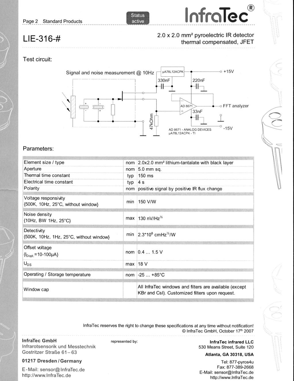
2 Lamp DC Power Supply + Volt Meter Current Meter The radiation detector is an InfraTec LIE-316-# pyroelectric detector with a CaFl window. This is a 2mm square lithium-tantalate capacitor, one plate of which is a blackened surface which approximates a black body absorber at radiation wavelengths from 400 to 10,000nm. The dielectric of this detector is permanently polarized; however, the magnitude of the polarization is temperature dependent. Therefore, a time dependent illumination of the detector changes its temperature and produces a charging current in an external circuit. Since the responsivity of the detector and its built in circuitry is only 150µV/µW of power, this very small signal is amplified by the first stage ac input amplifier of the Lock-In Amplifier. This amplifier has built into it a 60 hertz notch filter, designed to reject the 60 hertz components in the input signal. Even though the signal has been amplified and much of the 60 hertz noise removed, under conditions of the experiment, the signal is still buried in random noise. The next stage of the Lock-In is a phase sensitive detector which extracts the detector signal from the noise (refer to your notes from the Lock-In experiment). The light chopper modulates the light from the lamp and generates a reference signal at the chopping frequency. The phase sensitive detector chops the amplified input signal at the frequency of the reference signal. Since both are at the same frequency, the resultant signal waveform is rectified, and a dc voltage is produced. This dc voltage is a maximum when both signal and reference are exactly in phase. As oscilloscope can be used to monitor either the chopper reference signal or the amplified ac signal (before phase sensitive detection). Procedure 1. Familiarize yourself with all of the equipment, and read the appropriate manuals. 2. Cautions: a. The NaCl prism is moisture sensitive, therefore do not open up the spectrometer. b. The cables generate large electrostatic signals when moved, therefore don t move them.
3 c. The lock-in overload light indicates when the signal from the ac amplifier is too large for the psd. The phase quadrant and phase adjust controls shift the phase of the signal relative to the reference. The phase control should be adjusted for maximum signal. 3. Line up the lamp L and chopper C and turn on both (do not exceed 6 Amps for the lamp current). Connect the chopper reference to the lock-in reference input. Using a tee, you can also connect this reference signal to one input of the CRO. 4. Line up the lamp and monochromator and turn the lamp on (start with about 5.5 A). Set the spectrometer at 0.589µm and adjust the position of the lamp until the image is blinding. Insert the pyroelectric detector and connect it to the lock-in signal input. Set the monochromator to around µm. Adjust the sensitivity control to give a reading on scale, and the phase control for a maximum reading on the psd meter. Set the time constant to 1 or 3 seconds. Observe the lock-in output with and without the various notch filters. Why is it desirable to operate with the filters in? Play with the chopping frequency to determine the optimum value (best signal to noise ratio). Record what you learn. 5. Slowly scan the spectrum from.589µ to about 8µ, and roughly locate the region of peak intensity (remember that a 1 or 3 second time constant limits the response time of the system). Record intensity values which will enable you to plot the full spectrum, with special emphasis on data near the peak. Be sure to record both lamp current and voltage. Decrease the lamp current to ~4.2 A and repeat the above spectral scan. 5. Plot the intensities recorded with the higher lamp current as a function of wavelength. Determine the filament temperature for this lamp current using Wien s Displacement Law λ 3 o m T x = 10 m- K. Then plot the theoretical energy spectral distribution, derived by Planck, 5 8πhcλ λ U ( λ ) λ =. exp( hc / λkt) 1 Here λ is the bandpass of the spectrometer, λ is wavelength, h is Planck s constant, c is the speed of light, k is Boltzmann s constant and T is the Kelvin temperature. Since λ is approximately constant (it depends on the slit widths and the dispersion of NaCl), calculation 5 1 of λ [exp( hc / λkt) 1] is all that is required. The theoretical curve should be normalized to the experimental curve at the maximum. How good is the agreement between the shapes of the experimental and theoretical curves? Can you think of any factors that can explain any discrepancies you find? 6. Plot your data for the lower current setting on the same plot and in the same units. Once you know the lamp temperature at one current setting, there are a couple different methods you can use to try to determine the temperature at the other setting. One is to again look at the peak wavelength and use Wien s Displacement Law. A second is to note that the total power dissipated by the lamp is given by P = VI. Since the total power radiated is given by the Stefan-Boltzmann Law, you can estimate the temperature ratio from the ratio of the powers
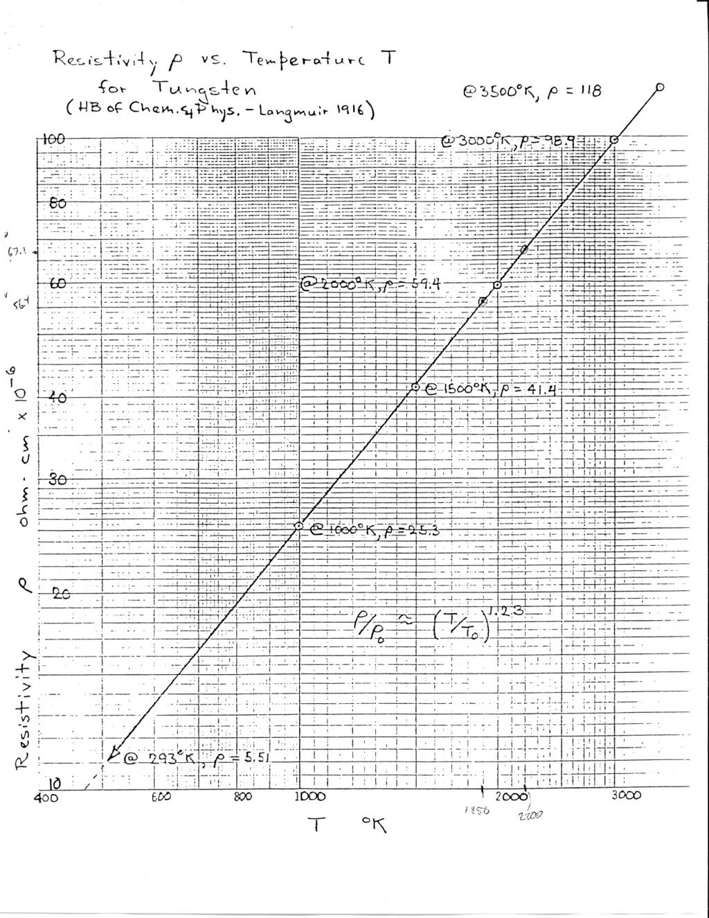
4 dissipated with the two current settings. Finally, the resistivity of tungsten exhibits simple power law behavior between T = 293 o C and 3000 o C (see graph); therefore, the change of resistance of the lamp can be used to measure its temperature change. The resistance R = ρ /A, where is filament length, A is filament cross-sectional area and ρ is resistivity. Since and A are constants, we have ( ) ( ) ( ) ( ) RT ρ T T = = RT0 ρ T0 T Thus by measuring the resistance at the higher and lower current settings, you can predict the temperature ratios. The experimental resistance R of the lamp is R = V I (meter readings). 7. Plot the theoretical spectrum for the lamp using each of the three estimates of the temperature corresponding to the lower lamp current. How do each of these theoretical curves compare to your experimental spectrum in terms of peak wavelength, overall (integrated) intensity, and shape of the curve? Which method of estimating the lamp temperature appears to be the best.
5
6
7
8
BLACKBODY RADIATION PHYSICS 359E
 BLACKBODY RADIATION PHYSICS 359E INTRODUCTION In this laboratory, you will make measurements intended to illustrate the Stefan-Boltzmann Law for the total radiated power per unit area I tot (in W m 2 )
The University of Toledo R. Ellingson and M. Heben
 focal length, f Spectral Measurement Using a Monochromator, Thermopile Detector, and Lock-In Amplifier September 18, 2012 The University of Toledo R. Ellingson and M. Heben Where are We, Where we are Going?
The equipment used share any common features regardless of the! being measured. Electronic detection was not always available.
 The equipment used share any common features regardless of the! being measured. Each will have a light source sample cell! selector We ll now look at various equipment types. Electronic detection was not
Spectroscopy of Ruby Fluorescence Physics Advanced Physics Lab - Summer 2018 Don Heiman, Northeastern University, 1/12/2018
 1 Spectroscopy of Ruby Fluorescence Physics 3600 - Advanced Physics Lab - Summer 2018 Don Heiman, Northeastern University, 1/12/2018 I. INTRODUCTION The laser was invented in May 1960 by Theodor Maiman.
Ultraviolet Visible Infrared Instrumentation
 Ultraviolet Visible Infrared Instrumentation Focus our attention on measurements in the UV-vis region of the EM spectrum Good instrumentation available Very widely used techniques Longstanding and proven
University of Wisconsin Chemistry 524 Spectroscopic Components *
 University of Wisconsin Chemistry 524 Spectroscopic Components * In journal articles, presentations, and textbooks, chemical instruments are often represented as block diagrams. These block diagrams highlight
SPECTRAL IRRADIANCE DATA
 The radiometric data on the following pages was measured in our Standards Laboratory. The wavelength calibrations are based on our spectral calibration lamps. Irradiance data from 250 to 2500 nm is based
Goals of the Lab: Photodetectors and Noise (Part 2) Department of Physics. Slide 1. PHYSICS6770 Laboratory 4
 Department of Physics. Slide 1. PHYSICS6770 Laboratory 4") Slide 1 Goals of the Lab: Understand the origin and properties of thermal noise Understand the origin and properties of optical shot noise In this lab, You will qualitatively and quantitatively determine
Slide 1 Goals of the Lab: Understand the origin and properties of thermal noise Understand the origin and properties of optical shot noise In this lab, You will qualitatively and quantitatively determine
CHAPTER 7. Components of Optical Instruments
 CHAPTER 7 Components of Optical Instruments From: Principles of Instrumental Analysis, 6 th Edition, Holler, Skoog and Crouch. CMY 383 Dr Tim Laurens NB Optical in this case refers not only to the visible
ECEN. Spectroscopy. Lab 8. copy. constituents HOMEWORK PR. Figure. 1. Layout of. of the
 ECEN 4606 Lab 8 Spectroscopy SUMMARY: ROBLEM 1: Pedrotti 3 12-10. In this lab, you will design, build and test an optical spectrum analyzer and use it for both absorption and emission spectroscopy. The
Oscilloscope Measurements
 PC1143 Physics III Oscilloscope Measurements 1 Purpose Investigate the fundamental principles and practical operation of the oscilloscope using signals from a signal generator. Measure sine and other waveform
Components of Optical Instruments. Chapter 7_III UV, Visible and IR Instruments
 Components of Optical Instruments Chapter 7_III UV, Visible and IR Instruments 1 Grating Monochromators Principle of operation: Diffraction Diffraction sources: grooves on a reflecting surface Fabrication:
Thermal Johnson Noise Generated by a Resistor
 Thermal Johnson Noise Generated by a Resistor Complete Pre- Lab before starting this experiment HISTORY In 196, experimental physicist John Johnson working in the physics division at Bell Labs was researching
Polarization Experiments Using Jones Calculus
 Polarization Experiments Using Jones Calculus Reference http://chaos.swarthmore.edu/courses/physics50_2008/p50_optics/04_polariz_matrices.pdf Theory In Jones calculus, the polarization state of light is
225 Lock-in Amplifier
 225 Lock-in Amplifier 225.02 Bentham Instruments Ltd 1 2 Bentham Instruments Ltd 225.02 1. WHAT IS A LOCK-IN? There are a number of ways of visualising the operation and significance of a lock-in amplifier.
Working in Visible NHMFL
 Working in Visible Optics @ NHMFL NHMFL Summer School 05-19-2016 Stephen McGill Optical Energy Range Energy of Optical Spectroscopy Range SCM3 Optics Facility Energy Range of Optical Spectroscopy SCM3
Instruction manual and data sheet ipca h
 1/15 instruction manual ipca-21-05-1000-800-h Instruction manual and data sheet ipca-21-05-1000-800-h Broad area interdigital photoconductive THz antenna with microlens array and hyperhemispherical silicon
DETECTORS Important characteristics: 1) Wavelength response 2) Quantum response how light is detected 3) Sensitivity 4) Frequency of response
 Wavelength response 2) Quantum response how light is detected 3) Sensitivity 4) Frequency of response") DETECTORS Important characteristics: 1) Wavelength response 2) Quantum response how light is detected 3) Sensitivity 4) Frequency of response (response time) 5) Stability 6) Cost 7) convenience Photoelectric
DETECTORS Important characteristics: 1) Wavelength response 2) Quantum response how light is detected 3) Sensitivity 4) Frequency of response (response time) 5) Stability 6) Cost 7) convenience Photoelectric
Intermediate Physics PHYS102
 Intermediate Physics PHYS102 Dr Richard H. Cyburt Assistant Professor of Physics My office: 402c in the Science Building My phone: (304) 384-6006 My email: rcyburt@concord.edu My webpage: www.concord.edu/rcyburt
EXPERIMENT NUMBER 8 Introduction to Active Filters
 EXPERIMENT NUMBER 8 Introduction to Active Filters i-1 Preface: Preliminary exercises are to be done and submitted individually. Laboratory hardware exercises are to be done in groups. This laboratory
Mechatronics. Analog and Digital Electronics: Studio Exercises 1 & 2
 Mechatronics Analog and Digital Electronics: Studio Exercises 1 & 2 There is an electronics revolution taking place in the industrialized world. Electronics pervades all activities. Perhaps the most important
EXPERIMENT 5 : THE DIODE
 EXPERIMENT 5 : THE DIODE Equipment List Dual Channel Oscilloscope R, 330, 1k, 10k resistors P, Tri-Power Supply V, 2x Multimeters D, 4x 1N4004: I max = 1A, PIV = 400V Silicon Diode P 2 35.6V pp (12.6 V
Spectrophotometer. An instrument used to make absorbance, transmittance or emission measurements is known as a spectrophotometer :
 Spectrophotometer An instrument used to make absorbance, transmittance or emission measurements is known as a spectrophotometer : Spectrophotometer components Excitation sources Deuterium Lamp Tungsten
ME 365 EXPERIMENT 7 SIGNAL CONDITIONING AND LOADING
 ME 365 EXPERIMENT 7 SIGNAL CONDITIONING AND LOADING Objectives: To familiarize the student with the concepts of signal conditioning. At the end of the lab, the student should be able to: Understand the
Measuring optical filters
 Measuring optical filters Application Note Author Don Anderson and Michelle Archard Agilent Technologies, Inc. Mulgrave, Victoria 3170, Australia Introduction Bandpass filters are used to isolate a narrow
Angela Piegari ENEA, Optical Coatings Laboratory, Roma, Italy
 Optical Filters for Space Instrumentation Angela Piegari ENEA, Optical Coatings Laboratory, Roma, Italy Trieste, 18 February 2015 Optical coatings for Space Instrumentation Spectrometers, imagers, interferometers,
CHAPTER 5 FINE-TUNING OF AN ECDL WITH AN INTRACAVITY LIQUID CRYSTAL ELEMENT
 CHAPTER 5 FINE-TUNING OF AN ECDL WITH AN INTRACAVITY LIQUID CRYSTAL ELEMENT In this chapter, the experimental results for fine-tuning of the laser wavelength with an intracavity liquid crystal element
7. Experiment K: Wave Propagation
 7. Experiment K: Wave Propagation This laboratory will be based upon observing standing waves in three different ways, through coaxial cables, in free space and in a waveguide. You will also observe some
Spectrally Selective Photocapacitance Modulation in Plasmonic Nanochannels for Infrared Imaging
 Supporting Information Spectrally Selective Photocapacitance Modulation in Plasmonic Nanochannels for Infrared Imaging Ya-Lun Ho, Li-Chung Huang, and Jean-Jacques Delaunay* Department of Mechanical Engineering,
Lab 12 Microwave Optics.
 b Lab 12 Microwave Optics. CAUTION: The output power of the microwave transmitter is well below standard safety levels. Nevertheless, do not look directly into the microwave horn at close range when the
Filters And Waveform Shaping
 Physics 3330 Experiment #3 Fall 2001 Purpose Filters And Waveform Shaping The aim of this experiment is to study the frequency filtering properties of passive (R, C, and L) circuits for sine waves, and
NON-AMPLIFIED PHOTODETECTOR USER S GUIDE
 NON-AMPLIFIED PHOTODETECTOR USER S GUIDE Thank you for purchasing your Non-amplified Photodetector. This user s guide will help answer any questions you may have regarding the safe use and optimal operation
EXPERIMENT 5 : THE DIODE
 EXPERIMENT 5 : THE DIODE Component List Resistors, one of each o 1 10 10W o 1 1k o 1 10k 4 1N4004 (I max = 1A, PIV = 400V) Diodes Center tap transformer (35.6V pp, 12.6 V RMS ) 100 F Electrolytic Capacitor
Advanced Features of InfraTec Pyroelectric Detectors
 1 Basics and Application of Variable Color Products The key element of InfraTec s variable color products is a silicon micro machined tunable narrow bandpass filter, which is fully integrated inside the
Chapter Ray and Wave Optics
 109 Chapter Ray and Wave Optics 1. An astronomical telescope has a large aperture to [2002] reduce spherical aberration have high resolution increase span of observation have low dispersion. 2. If two
Performance Comparisons of InGaAs, extended InGaAs, and Short-wave HgCdTe Detectors between 1 µm and 2.5 µm
 Performance Comparisons of, extended, and Short-wave HgCdTe Detectors between 1 µm and 2.5 µm Howard W. Yoon, Matt C. Dopkiss, and George P. Eppeldauer Optical Technology Division National Institute of
2.0 AC CIRCUITS 2.1 AC VOLTAGE AND CURRENT CALCULATIONS. ECE 4501 Power Systems Laboratory Manual Rev OBJECTIVE
 2.0 AC CIRCUITS 2.1 AC VOLTAGE AND CURRENT CALCULATIONS 2.1.1 OBJECTIVE To study sinusoidal voltages and currents in order to understand frequency, period, effective value, instantaneous power and average
Supplementary Figure 1. Effect of the spacer thickness on the resonance properties of the gold and silver metasurface layers.
 Supplementary Figure 1. Effect of the spacer thickness on the resonance properties of the gold and silver metasurface layers. Finite-difference time-domain calculations of the optical transmittance through
DC to 3.5-GHz Amplified Photoreceivers Models 1591 & 1592
 USER S GUIDE DC to 3.5-GHz Amplified Photoreceivers Models 1591 & 1592 These photoreceivers are sensitive to electrostatic discharges and could be permanently damaged if subjected even to small discharges.
EXPRIMENT 3 COUPLING FIBERS TO SEMICONDUCTOR SOURCES
 EXPRIMENT 3 COUPLING FIBERS TO SEMICONDUCTOR SOURCES OBJECTIVES In this lab, firstly you will learn to couple semiconductor sources, i.e., lightemitting diodes (LED's), to optical fibers. The coupling
(Oct revision) Physics 307 Laboratory Experiment #4 The Photoelectric Eect
 Physics 307 Laboratory Experiment #4 The Photoelectric Eect") (Oct. 2013 revision) Physics 307 Laboratory Experiment #4 The Photoelectric Eect Motivation: The photoelectric eect demonstrates that electromagnetic radiation (specically visible light) is composed of
(Oct. 2013 revision) Physics 307 Laboratory Experiment #4 The Photoelectric Eect Motivation: The photoelectric eect demonstrates that electromagnetic radiation (specically visible light) is composed of
NEEP 427 PROPORTIONAL COUNTERS. Knoll, Chapters 6 & 14 Sect. I & II
 NEEP 427 PROPORTIONAL COUNTERS References: Knoll, Chapters 6 & 14 Sect. I & II a proportional counter the height of the output pulse is proportional to the number of ion pairs produced in the counter gas.
Operational Amplifiers 2 Active Filters ReadMeFirst
 Operational Amplifiers 2 Active Filters ReadMeFirst Lab Summary In this lab you will build two active filters on a breadboard, using an op-amp, resistors, and capacitors, and take data for the magnitude
Comparison of Signal Attenuation of Multiple Frequencies Between Passive and Active High-Pass Filters
 Comparison of Signal Attenuation of Multiple Frequencies Between Passive and Active High-Pass Filters Aaron Batker Pritzker Harvey Mudd College 23 November 203 Abstract Differences in behavior at different
Calibration of a High Dynamic Range, Low Light Level Visible Source
 Calibration of a High Dynamic Range, Low Light Level Visible Source Joe LaVeigne a, Todd Szarlan a, Nate Radtke a a Santa Barbara Infrared, Inc., 30 S. Calle Cesar Chavez, #D, Santa Barbara, CA 93103 ABSTRACT
Department of Electrical Engineering and Computer Science, Massachusetts Institute of Technology, 77. Table of Contents 1
 Efficient single photon detection from 500 nm to 5 μm wavelength: Supporting Information F. Marsili 1, F. Bellei 1, F. Najafi 1, A. E. Dane 1, E. A. Dauler 2, R. J. Molnar 2, K. K. Berggren 1* 1 Department
DC to 12-GHz Amplified Photoreceivers Models 1544-B, 1554-B, & 1580-B
 USER S GUIDE DC to 12-GHz Amplified Photoreceivers Models 1544-B, 1554-B, & 1580-B Including multimode -50 option These photoreceivers are sensitive to electrostatic discharges and could be permanently
Experimental Physics. Experiment C & D: Pulsed Laser & Dye Laser. Course: FY12. Project: The Pulsed Laser. Done by: Wael Al-Assadi & Irvin Mangwiza
 Experiment C & D: Course: FY1 The Pulsed Laser Done by: Wael Al-Assadi Mangwiza 8/1/ Wael Al Assadi Mangwiza Experiment C & D : Introduction: Course: FY1 Rev. 35. Page: of 16 1// In this experiment we
THROUGHPUT OF AN OPTICAL INSTRUMENT CHEM 314
 THROUGHPUT OF AN OPTICAL INSTRUMENT CHEM 314 OBJECTIVES Calculate the number of photons present in a single beam UV- Vis: At the source Entering the monochromator Incident on the diffracgon gragng Emerging
Basic Components of Spectroscopic. Instrumentation
 Basic Components of Spectroscopic Ahmad Aqel Ifseisi Assistant Professor of Analytical Chemistry College of Science, Department of Chemistry King Saud University P.O. Box 2455 Riyadh 11451 Saudi Arabia
Section 1: SPECTRAL PRODUCTS
 Section 1: Optical Non-dispersive Wavelength Selection Filter Based Filter Filter Fundamentals Filter at an Incidence Angle Filters and Environmental Conditions Dispersive Instruments Grating and Polychromators
Components of Optical Instruments
 Components of Optical Instruments General Design of Optical Instruments Sources of Radiation Wavelength Selectors (Filters, Monochromators, Interferometers) Sample Containers Radiation Transducers (Detectors)
\Ç à{x ÇtÅx Éy ALLAH à{x `xüv yâä
 \Ç à{x ÇtÅx Éy ALLAH à{x `xüv yâä Ultraviolet Radiation from Some Types of Outdoor Lighting Lamps Dr.Essam El-Moghazy Photometry and Radiometry division, National Institute for Standards (NIS), Egypt.
Fundamental Optics ULTRAFAST THEORY ( ) = ( ) ( q) FUNDAMENTAL OPTICS. q q = ( A150 Ultrafast Theory
 = ( ) ( q) FUNDAMENTAL OPTICS. q q = ( A150 Ultrafast Theory") ULTRAFAST THEORY The distinguishing aspect of femtosecond laser optics design is the need to control the phase characteristic of the optical system over the requisite wide pulse bandwidth. CVI Laser Optics
ULTRAFAST THEORY The distinguishing aspect of femtosecond laser optics design is the need to control the phase characteristic of the optical system over the requisite wide pulse bandwidth. CVI Laser Optics
HR2000+ Spectrometer. User-Configured for Flexibility. now with. Spectrometers
 Spectrometers HR2000+ Spectrometer User-Configured for Flexibility HR2000+ One of our most popular items, the HR2000+ Spectrometer features a high-resolution optical bench, a powerful 2-MHz analog-to-digital
Extreme Sensitivity in Photoacoustics by Using Optical Cantilever-type Microphone
 Extreme Sensitivity in Photoacoustics by Using Optical Cantilever-type Microphone Jyrki Kauppinen, Vesa Koskinen, Minna Huuskonen Department of Physics, University of Turku, FIN-20014 TURKU, Finland, e-mail:
Mercury Cadmium Telluride Detectors
 Mercury Cadmium Telluride Detectors ISO 9001 Certified J15 Mercury Cadmium Telluride Detectors (2 to 26 µm) General HgCdTe is a ternary semiconductor compound which exhibits a wavelength cutoff proportional
R. J. Jones College of Optical Sciences OPTI 511L Fall 2017
 R. J. Jones College of Optical Sciences OPTI 511L Fall 2017 Active Modelocking of a Helium-Neon Laser The generation of short optical pulses is important for a wide variety of applications, from time-resolved
Experiment 12: Microwaves
 MASSACHUSETTS INSTITUTE OF TECHNOLOGY Department of Physics 8.02 Spring 2005 OBJECTIVES Experiment 12: Microwaves To observe the polarization and angular dependence of radiation from a microwave generator
Chemistry 524--"Hour Exam"--Keiderling Mar. 19, pm SES
 Chemistry 524--"Hour Exam"--Keiderling Mar. 19, 2013 -- 2-4 pm -- 170 SES Please answer all questions in the answer book provided. Calculators, rulers, pens and pencils permitted. No open books allowed.
Unit 8: Light and Optics
 Objectives Unit 8: Light and Optics Explain why we see colors as combinations of three primary colors. Explain the dispersion of light by a prism. Understand how lenses and mirrors work. Explain thermal
Laboratory 6. Lab 6. Operational Amplifier Circuits. Required Components: op amp 2 1k resistor 4 10k resistors 1 100k resistor 1 0.
 Laboratory 6 Operational Amplifier Circuits Required Components: 1 741 op amp 2 1k resistor 4 10k resistors 1 100k resistor 1 0.1 F capacitor 6.1 Objectives The operational amplifier is one of the most
College Physics II Lab 3: Microwave Optics
 ACTIVITY 1: RESONANT CAVITY College Physics II Lab 3: Microwave Optics Taner Edis with Peter Rolnick Spring 2018 We will be dealing with microwaves, a kind of electromagnetic radiation with wavelengths
SECOND HARMONIC GENERATION AND Q-SWITCHING
 SECOND HARMONIC GENERATION AND Q-SWITCHING INTRODUCTION In this experiment, the following learning subjects will be worked out: 1) Characteristics of a semiconductor diode laser. 2) Optical pumping on
6 Experiment II: Law of Reflection
 Lab 6: Microwaves 3 Suggested Reading Refer to the relevant chapters, 1 Introduction Refer to Appendix D for photos of the apparatus This lab allows you to test the laws of reflection, refraction and diffraction
Calibration of ARM Spectral Shortwave Radiometers
 Calibration of ARM Spectral Shortwave Radiometers J. J. Michalsky, J. L. Berndt, P. W. Kiedron, and L. C. Harrison Atmospheric Sciences Research Center State University of New York at Albany Albany, New
Photonic time-stretching of 102 GHz millimeter waves using 1.55 µm nonlinear optic polymer EO modulators
 Photonic time-stretching of 10 GHz millimeter waves using 1.55 µm nonlinear optic polymer EO modulators H. Erlig Pacific Wave Industries H. R. Fetterman and D. Chang University of California Los Angeles
Measurement Method of High Absorbance (Low Transmittance) Samples by UH4150 INTRODUCTION
 Samples by UH4150 INTRODUCTION") INTRODUCTION With UH4150, a detector can be selected depending on the analysis purpose. When analyzing a solid sample which doesn t contain any diffuse components, by selecting the direct light detector,
INTRODUCTION With UH4150, a detector can be selected depending on the analysis purpose. When analyzing a solid sample which doesn t contain any diffuse components, by selecting the direct light detector,
DWDM FILTERS; DESIGN AND IMPLEMENTATION
 DWDM FILTERS; DESIGN AND IMPLEMENTATION 1 OSI REFERENCE MODEL PHYSICAL OPTICAL FILTERS FOR DWDM SYSTEMS 2 AGENDA POINTS NEED CHARACTERISTICS CHARACTERISTICS CLASSIFICATION TYPES PRINCIPLES BRAGG GRATINGS
TracQ. Basic Data Acquisition and Spectroscopy Software
 Basic Data Acquisition and Spectroscopy Software TracQ Basic main application window. Many common spectroscopic measurements require coordinated operation of a detection instrument and light source, as
Laboratory #2 Guide: Measuring the Lamp/Monochromator Output Spectrum
 September 3, 2014 Laboratory #2 Guide: Measuring the Lamp/Monochromator Output Spectrum Introduction In the last lab we did a simple exercise to introduce students to the major components in our optical
Imaging Fourier transform spectrometer
 Rochester Institute of Technology RIT Scholar Works Theses Thesis/Dissertation Collections 2001 Imaging Fourier transform spectrometer Eric Sztanko Follow this and additional works at: http://scholarworks.rit.edu/theses
Physics 262. Lab #1: Lock-In Amplifier. John Yamrick
 Physics 262 Lab #1: Lock-In Amplifier John Yamrick Abstract This lab studied the workings of a photodiode and lock-in amplifier. The linearity and frequency response of the photodiode were examined. Introduction
Practical 2P12 Semiconductor Devices
 Practical 2P12 Semiconductor Devices What you should learn from this practical Science This practical illustrates some points from the lecture courses on Semiconductor Materials and Semiconductor Devices
Laboratory 9. Required Components: Objectives. Optional Components: Operational Amplifier Circuits (modified from lab text by Alciatore)
") Laboratory 9 Operational Amplifier Circuits (modified from lab text by Alciatore) Required Components: 1x 741 op-amp 2x 1k resistors 4x 10k resistors 1x l00k resistor 1x 0.1F capacitor Optional Components:
Laboratory 9 Operational Amplifier Circuits (modified from lab text by Alciatore) Required Components: 1x 741 op-amp 2x 1k resistors 4x 10k resistors 1x l00k resistor 1x 0.1F capacitor Optional Components:
UNIVERSITY OF NORTH CAROLINA AT CHARLOTTE Department of Electrical and Computer Engineering
 UNIVERSITY OF NORTH CAROLINA AT CHARLOTTE Department of Electrical and Computer Engineering EXPERIMENT 7 LAMPS OBJECTIVES The purpose of this experiment is to introduce the concept of resistance change
Exploring TeachSpin s Two-Slit Interference, One Photon at a Time Workshop Manual
 Introduction Exploring TeachSpin s Nobel Laureate Richard Feynman, one of the most joyous practitioners of physics, described single photon interference as a phenomenon which is impossible, absolutely
SCCH 4: 211: 2015 SCCH
 SCCH 211: Analytical Chemistry I Analytical Techniques Based on Optical Spectroscopy Atitaya Siripinyanond Office Room: C218B Email: atitaya.sir@mahidol.ac.th Course Details October 19 November 30 Topic
FPPO 1000 Fiber Laser Pumped Optical Parametric Oscillator: FPPO 1000 Product Manual
 Fiber Laser Pumped Optical Parametric Oscillator: FPPO 1000 Product Manual 2012 858 West Park Street, Eugene, OR 97401 www.mtinstruments.com Table of Contents Specifications and Overview... 1 General Layout...
EDUCATIONAL SPECTROPHOTOMETER ACCESSORY KIT AND EDUCATIONAL SPECTROPHOTOMETER SYSTEM
 GAIN 1 10 100 Instruction Manual and Experiment Guide for the PASCO scientific Model OS-8537 and OS-8539 012-06575A 3/98 EDUCATIONAL SPECTROPHOTOMETER ACCESSORY KIT AND EDUCATIONAL SPECTROPHOTOMETER SYSTEM
Bandpass Interference Filters
 Precise control of center wavelength and bandpass shape Wide selection of stock wavelengths from 250 nm-1550 nm Selection of bandwidths Available in 1/2 and 1 sizes High peak transmission values Excellent
1 Lock-in Amplifier Introduction
 1 Lock-in Amplifier Introduction The purpose of this laboratory is to introduce the student to the lock-in amplifier. A lock-in amplifier is a nearly ubiquitous piece of laboratory equipment, and can serve
1/8 m GRATING MONOCHROMATOR
 1/8 m GRATING GRATING OUTPUT PORT INPUT PORT 77250 1/8 m Monochromator with 6025 Hg(Ar) Spectral Calibration Lamp. Low cost, compact size and high performance, ideal for OEM applications Very efficient
06SurfaceQuality.nb Optics James C. Wyant (2012) 1
 1") 06SurfaceQuality.nb Optics 513 - James C. Wyant (2012) 1 Surface Quality SQ-1 a) How is surface profile data obtained using the FECO interferometer? Your explanation should include diagrams with the appropriate
06SurfaceQuality.nb Optics 513 - James C. Wyant (2012) 1 Surface Quality SQ-1 a) How is surface profile data obtained using the FECO interferometer? Your explanation should include diagrams with the appropriate
Instytut Fizyki Doświadczalnej Wydział Matematyki, Fizyki i Informatyki UNIWERSYTET GDAŃSKI
 Instytut Fizyki Doświadczalnej Wydział Matematyki, Fizyki i Informatyki UNIWERSYTET GDAŃSKI I. Background theory. 1. The temporal and spatial coherence of light. 2. Interaction of electromagnetic waves
ECE 2006 University of Minnesota Duluth Lab 11. AC Circuits
 1. Objective AC Circuits In this lab, the student will study sinusoidal voltages and currents in order to understand frequency, period, effective value, instantaneous power and average power. Also, the
Spectrometer using a tunable diode laser
 Spectrometer using a tunable diode laser Ricardo Vasquez Department of Physics, Purdue University, West Lafayette, IN April, 2000 In the following paper the construction of a simple spectrometer using
NIRCam optical calibration sources
 NIRCam optical calibration sources Stephen F. Somerstein, Glen D. Truong Lockheed Martin Advanced Technology Center, D/ABDS, B/201 3251 Hanover St., Palo Alto, CA 94304-1187 ABSTRACT The Near Infrared
Spectroscopy in the UV and Visible: Instrumentation. Spectroscopy in the UV and Visible: Instrumentation
 Spectroscopy in the UV and Visible: Instrumentation Typical UV-VIS instrument 1 Source - Disperser Sample (Blank) Detector Readout Monitor the relative response of the sample signal to the blank Transmittance
OPAC 202 Optical Design and Instrumentation. Topic 3 Review Of Geometrical and Wave Optics. Department of
 OPAC 202 Optical Design and Instrumentation Topic 3 Review Of Geometrical and Wave Optics Department of http://www.gantep.edu.tr/~bingul/opac202 Optical & Acustical Engineering Gaziantep University Feb
Ph 77 ADVANCED PHYSICS LABORATORY ATOMIC AND OPTICAL PHYSICS
 Ph 77 ADVANCED PHYSICS LABORATORY ATOMIC AND OPTICAL PHYSICS Diode Laser Characteristics I. BACKGROUND Beginning in the mid 1960 s, before the development of semiconductor diode lasers, physicists mostly
Mechatronics. Introduction to Analog and Digital Electronics: Laboratory Exercises 1 & 2
 Mechatronics Introduction to Analog and Digital Electronics: Laboratory Exercises 1 & 2 There is an electronics revolution taking plac thdustrialized world. Electronics pervades all activities. Perhaps
MAHALAKSHMI ENGINEERING COLLEGE TIRUCHIRAPALLI
 MAHALAKSHMI ENGINEERING COLLEGE TIRUCHIRAPALLI - 621213 DEPARTMENT : ECE SUBJECT NAME : OPTICAL COMMUNICATION & NETWORKS SUBJECT CODE : EC 2402 UNIT IV: FIBER OPTIC RECEIVER AND MEASUREMENT PART -A (2
Ph 3455 The Franck-Hertz Experiment
 Ph 3455 The Franck-Hertz Experiment Required background reading Tipler, Llewellyn, section 4-5 Prelab Questions 1. In this experiment, we will be using neon rather than mercury as described in the textbook.
PHY 351/651 LABORATORY 5 The Diode Basic Properties and Circuits
 Reading Assignment Horowitz, Hill Chap. 1.25 1.31 (p35-44) Data sheets 1N4007 & 1N4735A diodes Laboratory Goals PHY 351/651 LABORATORY 5 The Diode Basic Properties and Circuits In today s lab activities,
Microwave Optics. Department of Physics & Astronomy Texas Christian University, Fort Worth, TX. January 16, 2014
 Microwave Optics Department of Physics & Astronomy Texas Christian University, Fort Worth, TX January 16, 2014 1 Introduction Optical phenomena may be studied at microwave frequencies. Visible light has
Photoelectric effect
 Photoelectric effect Objective Study photoelectric effect. Measuring and Calculating Planck s constant, h. Measuring Current-Voltage Characteristics of photoelectric Spectral Lines. Theory Experiments
APPLICATION NOTE. Making Accurate Voltage Noise and Current Noise Measurements on Operational Amplifiers Down to 0.1Hz. Abstract
 APPLICATION NOTE Making Accurate Voltage Noise and Current Noise Measurements on Operational Amplifiers Down to 0.1Hz AN1560 Rev.1.00 Abstract Making accurate voltage and current noise measurements on
UV-VIS-IR Spectral Responsivity Measurement System for Solar Cells
 November 1998 NREL/CP-52-25654 UV-VIS-IR Spectral Responsivity Measurement System for Solar Cells H. Field Presented at the National Center for Photovoltaics Program Review Meeting, September 8 11, 1998,
10-Gbit/s 850-nm VCSEL Model 1780
 USER S GUIDE 10-Gbit/s 850-nm VCSEL Model 1780 Caution - Use of controls or adjustments or performance of procedures other than those specified herein may result in hazardous radiation exposure. Caution