IRDC3822A. Rev /22/2008 1
|
|
|
- Lesley Todd
- 6 years ago
- Views:
Transcription
1 02/22/2008
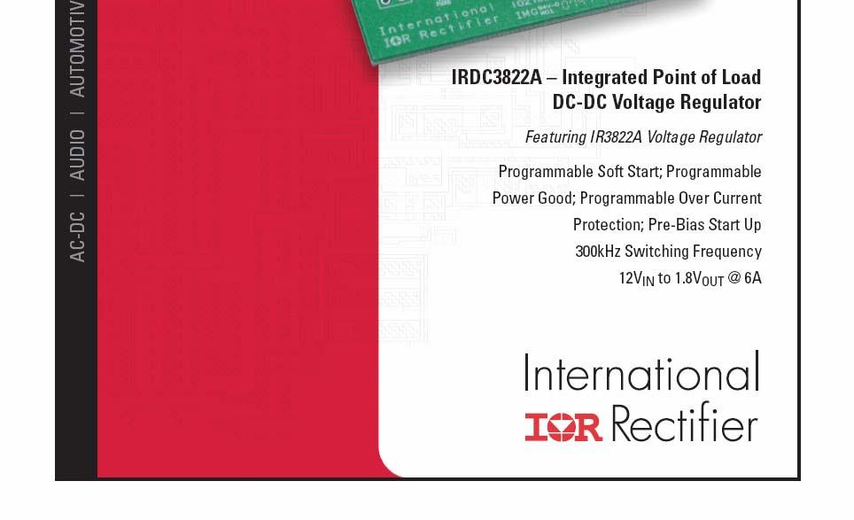
2 SupIRBuck TM DESCRIPTION USER GUIDE FOR IR3822A EVALUATION BOARD The IR3822A is a synchronous buck converter, providing a compact, high performance and flexible solution in a small 5mmx6mm Power QFN package. Key features offered by the IR3822A include programmable soft-start ramp, precision 0.6V reference voltage, programmable Power Good, thermal protection, fixed 300kHz switching frequency requiring no external component, input under-voltage lockout for proper start-up, and pre-bias start-up. An output over-current protection function is implemented by sensing the voltage developed across the on-resistance of the synchronous rectifier MOSFET for optimum cost and performance. This user guide contains the schematic and bill of materials for the IR3822A evaluation board. The guide describes operation and use of the evaluation board itself. Detailed application information for IR3822A is available in the IR3822A data sheet. BOARD FEATURES V in = +2V (3.2V Max) V out = 0-6A L= 2.2uH C in = 3x0uF (ceramic 206) + 330uF (electrolytic) C out = 6x22uF (ceramic 0805) 02/22/2008 2
3 CONNECTIONS and OPERATING INSTRUCTIONS A well regulated +2V input supply should be connected to VIN+ and VIN-. A maximum 6A load should be connected to VOUT+ and VOUT-. The connection diagram is shown in Fig. and inputs and outputs of the board are listed in Table I. IR3822A has two input supplies, one for biasing (Vcc) and the other as input voltage (Vin). These inputs are connected on the board with a zero ohm resistor (R5). Separate supplies can be applied to these inputs. Vcc input cannot be connected unless R5 is removed. Vcc input should be a well regulated 5V-2V supply and it would be connected to Vcc+ and Vcc-. Table I. Connections Connection VIN+ VIN- Vcc+ Vcc- VOUT- VOUT+ P_Good Signal Name V in (+2V) Ground of V in Optional Vcc input Ground for Optional Vcc input Ground of V out V out (+.8V) Power Good Signal LAYOUT The PCB is a 4-layer board. All of layers are 2 Oz. copper. The IR3822A SupIRBuck and all of the passive components are mounted on the top side of the board. Power supply decoupling capacitors, the charge-pump capacitor and feedback components are located close to IR3822A. The feedback resistors are connected to the output voltage at the point of regulation and are located close to the SupIRBuck. To improve efficiency, the circuit board is designed to minimize the length of the on-board power ground current path. 02/22/2008 3

4 IRDC3822A Connection Diagram Vin = +2v GROUND GROUND VCC+ GROUND VOUT = +.8v PGood Fig. : Connection diagram of IR3822A evaluation board 02/22/2008 4
")
5 Fig. 2: Board layout, top overlay Fig. 3: Board layout, bottom overlay (rear view) 02/22/2008 5


6 Fig. 4: Board layout, mid-layer I. AGND Plain PGND Plain Single point connection between AGND and PGND. Fig. 5: Board layout, mid-layer II. 02/22/2008 6
7 0 Vin Vin+ C0 0.22uF C24 000pF PGND C2 0.uF C2 + + C22 C4 0.uF C23 D BAT54S 3 2 R0 R9 0 R 34.8k J SS C26 000pF D2 C5 C4 0uF C3 0uF C2 0uF C25 0.uF C5 22uF C6 22uF C7 22uF C8 22uF C9 22uF C20 22uF Vout C3 uf R2 2.4K R4 C9 2.6K R2 R6 R3 40.2K 80.6k A 20 B 2 Agnd R8 C7 0.uF + C 330uF U Vsns VCC IR3822A L 2.2uH Vout+ C8 80pF Single point of connection between Power Ground and Signal ( analog ) Ground Fig. 6: Schematic of the IR3822A evaluation board 5 AGnd3 Vc Hg COMP AGnd2 SW 9 PGood 7 FB AGnd SS OCset Vin PGnd Vcc PGood VCC R7 0K R6 3.09k C 22pF R4 0k Vin+ C6 Vout- VCC Vcc- Vcc+ R5 Vin- Vout- Vin- Vout+ 02/22/2008 7
8 Bill of Materials Item Quantity Designator Value Description Size Manufacturer Mfr. Part Number C 330uF SMD Electrolytic, 25V, 20% SMD Panasonic EEV-FKE33P 2 3 C2 C3 C4 0uF Ceramic, 6V, X7R, 0% 206 Panasonic ECJ-3YXC06K 3 4 C7 C2 C4 C25 0.uF Ceramic, 50V, X7R, 0% 0603 Panasonic ECJ-VBH04K 4 C0 0.22uF Ceramic, 0V, X5R, 0% 0603 Panasonic ECJ-VBA224K 5 C8 80pF Ceramic, 50V, NPO, 5% 0603 Murata GRM885CH8JA0 6 C 22pF Ceramic, 50V, NPO, 5% 0603 Murata GRM885CH220JA0 7 C3 uf Ceramic, 6V, X5R, 0% 0603 Panasonic ECJ-VBC05K 8 6 C5 C6 C7 C8 C9 C20 22uF Ceramic, 6.3V, X5R, 20% 0805 Panasonic ECJ-2FB0J226M 9 2 C24, C26 000pF Ceramic, 50V, NPO, 5% 0603 Murata GRM885CH02JA0 0 D BAT54S Diode Schottky,40V, 200mA SOT-23 Fairchild BAT54S L 2.2uH SMT Inductor, 4.2mOhm,.8x 20% 0.5mm ACT STS205-2R2 2 R 34.8K Thick film, /0W, % 0603 Vishey/Dale CRCW060334K8FKEA 3 R3 40.2K Thick film, /0W, % 0603 Vishey/Dale CRCW060340K2FKEA 4 R2 80.6K Thick film, /0W, % 0603 Vishey/Dale CRCW060380K6FKEA 5 R4 2.6K Thick film, /0W, % 0603 Vishey/Dale CRCW06032K6FKEA 6 R6 20 Thick film, /0W, % 0603 Vishey/Dale CRCW060320R0FKEA 7 2 R9 R5 0 Thick film, /0W, % 0603 Vishey/Dale CRCW Z0EA 8 R2 2.4K Thick film, /0W, % 0603 Vishey/Dale CRCW06032K4FKEA 9 2 R4, R7 0K Thick film, /0W, % 0603 Vishey/Dale CRCW06030K0FKEA 20 R6 3.09K Thick film, /0W, % 0603 Vishey/Dale CRCW06033K09FKEA 2 U IR3822A 300kHz, 6A, SupIRBuck 5x6mm International Module Rectifier IR3822A Banana Jack, Insulated Johnson - Solder Terminal, Black Components Banana Jack- Insulated Johnson - Solder Terminal, Red Components Banana Jack- Insulated Solder Terminal, Green - Johnson Components /22/2008 8
9 TYPICAL OPERATING WAVEFORMS Vin=Vcc=2.0V, Vo=.8V, Io=0-6A, Room Temperature, No Air Flow Fig. 7: Start up at 6A Load Ch :V in, Ch 2 :V SS, Ch 3 :V out, Ch 4 :I out Fig. 8: Start up at 6A Load, Ch :V in, Ch 2 :V SS, Ch 3 :V out, Ch 4 :V PGood Fig. 9: Start up with 0.5V Pre Bias, 0A Load, Ch :V in, Ch 2 :V SS, Ch 3 :V out Fig. 0: Output Voltage Ripple, 6A load Ch : V out, Ch 4 : I out Fig. : Inductor node at 6A load Ch :LX, Ch 4 :I out Fig. 2: Short (Hiccup) Recovery Ch :V SS, Ch 2 :V out 02/22/2008 9
10 TYPICAL OPERATING WAVEFORMS Vin=Vcc=2V, Vo=.8V, Io=3A- 6A, Room Temperature, No Air Flow Fig. 3: Transient Response, 3A to 6A step Ch :V out, Ch 4 :I out 02/22/2008 0

11 TYPICAL OPERATING WAVEFORMS Vin=Vcc=2V, Vo=.8V, Io=6A, Room Temperature, No Air Flow Fig. 4: Bode Plot at 6A load shows a bandwidth of 52.7kHz and phase margin of 52 degrees 02/22/2008
12 TYPICAL OPERATING WAVEFORMS Vin=2V, Vo=.8V, Io=0-6A, Room Temperature, No Air Flow 85 Efficiency (%) Load Current (A) Efficiency Vin=Vcc=2V Efficiency Vin=2V Vcc=5V Fig.5: Efficiency versus load current 2.2 Power Loss (W) Load Current (A) Power Loss Vin=Vcc=2V Power Loss Vin=2V Vcc=5V Fig.6: Power loss versus load current 02/22/2008 2

13 THERMAL IMAGES Vin=2V, Vo=.8V, Io=6A, Room Temperature, No Air Flow Fig. 7: Thermal Image at 6A load Test point 3 is IR3822A 02/22/2008 3
14 PCB Metal and Components Placement The lead lands (the IC pins) width should be equal to the nominal part lead width. The minimum lead to lead spacing should be 0.2mm to minimize shorting. Lead land length should be equal to the maximum part lead length mm outboard extension. The outboard extension ensures a large and inspectable toe fillet. The pad lands (the 4 big pads other than the IC pins) length and width should be equal to maximum part pad length and width. However, the minimum metal to metal spacing should be no less than 0.7mm for 2 oz. Copper; no less than 0.mm for oz. Copper and no less than 0.23mm for 3 oz. Copper. 02/22/2008
15 Solder Resist It is recommended that the lead lands are Non Solder Mask Defined (NSMD). The solder resist should be pulled away from the metal lead lands by a minimum of 0.025mm to ensure NSMD pads. The land pad should be Solder Mask Defined (SMD), with a minimum overlap of the solder resist onto the copper of 0.05mm to accommodate solder resist mis-alignment. Ensure that the solder resist in between the lead lands and the pad land is 0.5mm due to the high aspect ratio of the solder resist strip separating the lead lands from the pad land. 02/22/2008
16 Stencil Design The Stencil apertures for the lead lands should be approximately 80% of the area of the lead lads. Reducing the amount of solder deposited will minimize the occurrences of lead shorts. If too much solder is deposited on the center pad the part will float and the lead lands will be open. The maximum length and width of the land pad stencil aperture should be equal to the solder resist opening minus an annular 0.2mm pull back to decrease the incidence of shorting the center land to the lead lands when the part is pushed into the solder paste. 02/22/2008
")


17 02/22/2008 IR WORLD HEADQUARTERS: 233 Kansas St., El Segundo, California 90245, USA Tel: (30) TAC Fax: (30) This product has been designed and qualified for the Consumer market. Visit us at for sales contact information Data and specifications subject to change without notice. /07
SupIRBuck TM IRDC3840W USER GUIDE FOR IR3840W EVALUATION BOARD DESCRIPTION BOARD FEATURES
 SupIRBuck TM DESCRIPTION USER GUIDE FOR IR3840W EVALUATION BOARD The IR3840W is a synchronous buck converter, providing a compact, high performance and flexible solution in a small 5mmx6mm Power QFN package.
SupIRBuck TM IRDC3841W USER GUIDE FOR IR3841W EVALUATION BOARD DESCRIPTION BOARD FEATURES
 IRDC384W SupIRBuck TM DESCRIPTION USER GUIDE FOR IR384W EVALUATION BOARD The IR384W is a synchronous buck converter, providing a compact, high performance and flexible solution in a small 5mmx6mm Power
SupIRBuck TM IRDC3856 USER GUIDE FOR IR3856 EVALUATION BOARD DESCRIPTION BOARD FEATURES
 SupIRBuck TM DESCRIPTION USER GUIDE FOR IR3856 EVALUATION BOARD The IR3856 is a synchronous buck converter, providing a compact, high performance and flexible solution in a small 4mmx5mm Power QFN package.
SupIRBuck TM IRDC3839 USER GUIDE FOR IR3839 EVALUATION BOARD DESCRIPTION BOARD FEATURES
 SupIRBuck TM DESCRIPTION USER GUIDE FOR IR3839 EVALUATION BOARD The IR3839 SupIRBuck TM is an easy-to-use, fully integrated and highly efficient DC/DC regulator. The onboard PWM controller and MOSFETs
IRDC3640 USER GUIDE FOR IR3640 EVALUATION BOARD DESCRIPTION BOARD FEATURES
 USER GUIDE FOR IR3640 EVALUATION BOARD DESCRIPTION The IR3640 is a PWM controller for use in high performance synchronous Buck DC/DC applications. This is designed to drive a pair of external NFETs using
SupIRBuck TM IRDC3846-P1V2 USER GUIDE FOR IRDC3846 EVALUATION BOARD DESCRIPTION BOARD FEATURES
 SupIRBuck TM USER GUIDE FOR IRDC3846 EVUATION BOARD DESCRIPTION IRDC3846-PV2 The IR3846 is a synchronous buck converter, providing a compact, high performance and flexible solution in a small 5mmx7mm QFN
SupIRBuck TM IRDC3447-P0V9 USER GUIDE FOR IR3447 EVALUATION BOARD DESCRIPTION BOARD FEATURES
 SupIRBuck TM USER GUIDE FOR IR3447 EVUATION BOARD DESCRIPTION IRDC3447-P0V9 The IR3447 is a synchronous buck converter, providing a compact, high performance and flexible solution in a small 5mmx6mm QFN
SupIRBuck TM IRDC3710-DF USER GUIDE FOR IRDC3710-DF EVALUATION BOARD DESCRIPTION BOARD FEATURES
 SupIRBuck TM IRDC3710-DF USER GUIDE FOR IRDC3710-DF EVALUATION BOARD DESCRIPTION The IR3710M is single phase sync-buck PWM controller IC optimized for efficiency in high performance portable electronics.
Overview. Demoboard Quick Start Guide Initial Settings: IRDCiP1203-A Recommended Operating Conditions
 International Rectifier 233 Kansas Street, El Segundo, CA 90245 USA IRDCiP1203-A: 400kHz, 15A, Synchronous Buck Converter Using ip1203 Overview This reference design is capable of delivering a continuous
IRDCiP2005A-B. Overview. IRDCiP2005A-B Recommended Operating Conditions. Demoboard Quick Start Guide Initial Settings:
 REFERENCE DESIGN IRDCiP2005A-B International Rectifier 233 Kansas Street, El Segundo, CA 90245 USA IRDCiP2005A-B: 500kHz, 60A, Synchronous Buck Converter Using IR3623+iP2005A Overview This reference design
IRPP A POWIR+ Chipset Reference Design #0612
 IRPP3624-12A POWIR+ Chipset Reference Design #0612 12Amp Single Phase Synchronous Buck POWIR+ TM Chipset Reference Design using IR3624MPBF PWM & Driver IC and IRF7823 and IRF7832Z MOSFET By Steve Oknaian,
IRDCiP2021C-1. Overview. IRDCiP2021C-1 Recommended Operating Conditions. Demoboard Quick Start Guide Initial Settings:
 REFERENCE DESIGN IRDCiPC- International Rectifier 33 Kansas Street, El Segundo, CA 945 USA IRDCiPC-: 5kHz, 4A, Single Output, Dual Phase Synchronous Buck Converter Featuring ipc and IR363M Overview This
This reference design is capable of delivering a continuous current of 60A without heatsink at an ambient temperature of 45ºC and airflow of 200LFM.
 REFERENCE DESIGN IRDCiP2005C-1 International Rectifier 233 Kansas Street, El Segundo, CA 90245 USA IRDCiP2005C-1: 500kHz, 60A, Single Output, Dual Phase Synchronous Buck Converter Featuring ip2005c and
IRPP A POWIR+ Chipset Reference Design
 IRPP3637-12A POWIR+ Chipset Reference Design 12Amp Single Phase Synchronous Buck POWIR+ TM Chipset Reference Design using IR3637SPBF PWM & Driver IC and IRF7823PBF & IRF7832ZPBF SO-8 MOSFETs By Steve Oknaian,
SYNCHRONOUS BUCK LGA POWER BLOCK
 Features 0A Multiphase building block No derating up to T C = T PCB = 95ºC Optimized for low power loss Bias supply range of.5v to 6.0V Operation up to 1.5MHz Over temperature protection Bi-directional
IRDCiP2005C-2. Overview. IRDCiP2005C-2 Recommended Operating Conditions. Demoboard Quick Start Guide Initial Settings:
 REFERENCE DESIGN IRDCiP2005C-2 International Rectifier 233 Kansas Street, El Segundo, CA 90245 USA IRDCiP2005C-2: 500kHz, 30A, Dual Output, 180 o Out of Phase Synchronous Buck Converter Featuring ip2005c
IRPP A POWIR+ Chipset Reference Design
 IRPP3637-18A POWIR+ Chipset Reference Design 18Amp Single Phase Synchronous Buck POWIR+ TM Chipset Reference Design using IR3637SPBF PWM & Driver IC and IRLR8713PBF & IRLR7843PBF D-Pak MOSFETs By Steve
IRDC3146EVAL IRU3146 EVALUATION BOARD USER GUIDE. INPUT/OUTPUT CONNECTIONS The following is the input/output connections: Dual Outputs.
 DCEVAL U EVALUATION OARD USER GUIDE INTRODUCTION The U IC is a Dual synchronous uck controller, providing a cost-effective, high performance and flexible solution. The U can be configured as a -independent
Purpose. Table of Contents. Purpose Introduction General Product Information Key Performance Summary Table... 3
 Purpose The RT8295A is a high-efficiency current mode synchronous step-down regulator that can deliver up to 2A output current from a wide input voltage range of 4.5V to 23V. This document explains the
IRDC3883 P3V3 user guide
 UG_2062_PL7_02 IRDC3883 P3V3 user guide About this document Scope and purpose The IR3883 is a synchronous buck converter, providing a compact, high performance and flexible solution in a small 3mm X 3
Design Note DN05009/D High Efficiency 3A Buck Regulator w/ Light Load Efficiency
 DN59/D Design Note DN59/D High Efficiency 3A Buck Regulator w/ Light Load Efficiency Device Application Input Output Output Topology Voltage Voltage Current NCP317A Consumer Electronic 5V & 12V 1.V-5.V
Evaluation Board for ADP2118 EVAL-ADP2118
 Evaluation Board for ADP8 EVAL-ADP8 GENERAL DESCRIPTION The evaluation (demo) board provides an easy way to evaluate the ADP8 buck regulator. This data sheet describes how to quickly set up the board to
IRDCiP2005A-A. Overview. Demo board Quick Start Guide Initial Settings: IRDCiP2005A-A Recommended Operating Conditions
 REFERENCE DESIGN IRDCiP2005A-A International Rectifier 233 Kansas Street, El Segundo, CA 90245 USA IRDCiP2005A-A: 1MHz, 65A DC, 80A Peak, Dual Phase, Sync Buck Converter using ip2005 Overview This reference
HM V 2A 500KHz Synchronous Step-Down Regulator
 Features HM8114 Wide 4V to 30V Operating Input Range 2A Continuous Output Current Fixed 500KHz Switching Frequency No Schottky Diode Required Short Protection with Hiccup-Mode Built-in Over Current Limit
TFT-LCD DC/DC Converter with Integrated Backlight LED Driver
 TFT-LCD DC/DC Converter with Integrated Backlight LED Driver Description The is a step-up current mode PWM DC/DC converter (Ch-1) built in an internal 1.6A, 0.25Ω power N-channel MOSFET and integrated
DESCRIPTION FEATURES APPLICATIONS TYPICAL APPLICATION. 500KHz, 18V, 2A Synchronous Step-Down Converter
 DESCRIPTION The is a fully integrated, high-efficiency 2A synchronous rectified step-down converter. The operates at high efficiency over a wide output current load range. This device offers two operation
EVQ4470-L-00A High-Efficiency, Fast-Transient, 5A, 36V Step-Down Converter Evaluation Board
 EVQ4470-L-00A High-Efficiency, Fast-Transient, 5A, 36V Step-Down Converter Evaluation Board DESCRIPTION The EVQ4470-L-00A is an evaluation board for the MPQ4470, a high-efficiency step-down regulator with
10A HIGHLY INTEGRATED WIDE-INPUT VOLTAGE, SYNCHRONOUS BUCK REGULATOR
 SupIRBuck TM Features Input Voltage Range: 3V to 26V Output Voltage Range: 0.5V to 12V Continuous 10A Load Capability Constant On-Time control Excellent Efficiency at very low output current levels Gate
Evaluates: MAX17532 (TDFN) in 5V Output Voltage Applications. MAX V Output Evaluation Kit (TDFN) General Description. Features.
 in 5V Output Voltage Applications. MAX V Output Evaluation Kit (TDFN) General Description. Features.") General Description The MAX753 5V evaluation kit (EV kit) (TDFN) is a fully assembled and tested circuit board that demonstrates the performance of the MAX753 4V, 00mA ultra-small, high-efficiency, synchronous
General Description The MAX753 5V evaluation kit (EV kit) (TDFN) is a fully assembled and tested circuit board that demonstrates the performance of the MAX753 4V, 00mA ultra-small, high-efficiency, synchronous
PAM2421 EVB User Guide
 EV Board User Guide AE Department 1. Revision Information PAM2421 Date Revision Description Comment 2011/09 V1.0 Initial Release 2. PAM2804 General Description The PAM2421 devices are high-performance,
November 2013 Rev VIN FDMS7578. L1 IHLP-5050FD-01 41A, 1mOhm. Csnub 0 Ohm FDMS7650DC. 0 Ohm. 6.8nF. CFF 0.56nF
 XRP64 November 0 Rev..0.0 GENERAL DESCRIPTION The XRP64 is a synchronous step-down controller for point-of load supplies up to 5A. A wide 4.5V to V input voltage range allows for single supply operation
Evaluates: MAX17544 in 5V Output-Voltage Application. MAX V Output Evaluation Kit. General Description. Features.
 MAX7544 5V Output Evaluation Kit Evaluates: MAX7544 in General Description The MAX7544 5V output evaluation kit (EV kit) provides a proven design to evaluate the MAX7544 high-voltage, high-efficiency,
Evaluates: MAX17761 in 5V Output-Voltage Application. MAX V Output Evaluation Kit. General Description. Quick Start.
 General Description The MAX17761 5V output EV kit is a proven design to evaluate the MAX17761 high-efficiency, high-voltage, synchronous step-down DC-DC converter in a TDFN package. The EV kit generates
MP A, 5.5V Synchronous Step-Down Switching Regulator
 The Future of Analog IC Technology DESCRIPTION The MP2120 is an internally compensated 1.5MHz fixed frequency PWM synchronous step-down regulator. MP2120 operates from a 2.7V to 5.5V input and generates
Evaluation Board for ADP2114 EVAL-ADP2114
 Evaluation Board for ADP EVAL-ADP FEATURES Full-featured demo board for the ADP Standalone capability Configurable dual synchronous step-down, dc-to-dc switching regulator Dual A/ A or A/ A output or single
8A HIGHLY INTEGRATED WIDE-INPUT VOLTAGE, SYNCHRONOUS BUCK REGULATOR
 PD-9747 IR3871MPBF SupIRBuck TM 8A HIGHLY INTEGRATED WIDE-INPUT VOLTAGE, SYNCHRONOUS BUCK REGULATOR Features Input Voltage Range: 3V to 6V Output Voltage Range: 0.5V to 1V Continuous 8A Load Capability
Design Note DN05019/D 200V Boost Regulator
 Design Note DN05019/D 200V Boost Regulator Device Application Input Voltage Output Voltage Output Current CS5171 General 12V 200V 20mA Topology Enhanced Boost Circuit Description The following solution
HM V 3A 500KHz Synchronous Step-Down Regulator
 Features Wide 4V to 18V Operating Input Range 3A Continuous Output Current 500KHz Switching Frequency Short Protection with Hiccup-Mode Built-in Over Current Limit Built-in Over Voltage Protection Internal
MP2314 High Efficiency 2A, 24V, 500kHz Synchronous Step Down Converter
 The Future of Analog IC Technology MP2314 High Efficiency 2A, 24V, 500kHz Synchronous Step Down Converter DESCRIPTION The MP2314 is a high frequency synchronous rectified step-down switch mode converter
Evaluates: MAX17546 in 5V Output-Voltage Application. MAX V Output Evaluation Kit. General Description. Quick Start.
 MAX7546 5V Output Evaluation Kit Evaluates: MAX7546 in 5V Output-Voltage Application General Description The MAX7546 5V output evaluation kit (EV kit) provides a proven design to evaluate the MAX7546 high-voltage,
MP8619 8A, 25V, 600kHz Synchronous Step-down Converter
 The Future of Analog IC Technology DESCRIPTION The MP8619 is a high frequency synchronous rectified step-down switch mode converter with built in internal power MOSFETs. It offers a very compact solution
IR3476 FEATURES DESCRIPTION APPLICATIONS EFFICIENCY BASIC APPLICATION. 12A Highly Integrated SupIRBuck TM
 FEATURES Input Voltage Range: 3V to 7V Output Voltage Range: 0.5V to 1V Continuous 1A Load Capability Constant On Time Control Compensation Loop not Required Excellent Efficiency at Very Low Output Currents
IR3742 APPLICATIONS ORDERING INFORMATION. 20A Integrated PowIRstage
 20A Integrated PowIRstage IR3742 FEATURES Single input voltage range from 5V to 21V Wide input voltage range from 1.0V to 21V with external V CC bias voltage Integrated MOSFET drivers, Control FET, Synchronous
CAD Layout Recommendations for the PowerBlox Family
 Solved by APPLICATION NOTE ANP4 TM CAD Layout Recommendations for the PowerBlox Family Introduction The Sipex PowerBlox family of parts offers designers a very high power density solution for wide input
Evaluates: MAX V Output-Voltage Application. MAX17632C Evaluation Kit. General Description. Quick Start. Features. Recommended Equipment
 General Description The MAX17632C 5V output evaluation kit (EV kit) provides a proven design to evaluate the MAX17632C highefficiency, synchronous step-down DC-DC converter. The EV kit provides 5V/2A at
Evaluates: MAX17574 in 3.3V Output-Voltage Application. MAX V Output Evaluation Kit. General Description. Quick Start.
 General Description The MAX17574 3.3V output evaluation kit (EV kit) provides a proven design to evaluate the MAX17574 high-voltage, high-efficiency, synchronous step-down DC-DC converter. The EV kit is
1MHz, 3A Synchronous Step-Down Switching Voltage Regulator
 FEATURES Guaranteed 3A Output Current Efficiency up to 94% Efficiency up to 80% at Light Load (10mA) Operate from 2.8V to 5.5V Supply Adjustable Output from 0.8V to VIN*0.9 Internal Soft-Start Short-Circuit
DT V 1A Output 400KHz Boost DC-DC Converter FEATURES GENERAL DESCRIPTION APPLICATIONS ORDER INFORMATION
 GENERAL DESCRIPTION The DT9111 is a 5V in 12V 1A Out step-up DC/DC converter The DT9111 incorporates a 30V 6A N-channel MOSFET with low 60mΩ RDSON. The externally adjustable peak inductor current limit
SR A, 30V, 420KHz Step-Down Converter DESCRIPTION FEATURES APPLICATIONS TYPICAL APPLICATION
 SR2026 5A, 30V, 420KHz Step-Down Converter DESCRIPTION The SR2026 is a monolithic step-down switch mode converter with a built in internal power MOSFET. It achieves 5A continuous output current over a
Evaluates: MAX17552 (TDFN) in 5V Output Voltage Applications. MAX V Output Evaluation Kit (TDFN) General Description.
 in 5V Output Voltage Applications. MAX V Output Evaluation Kit (TDFN) General Description.") General Description The MAX7552 5V evaluation kit (EV kit) (TDFN) is a fully assembled and tested circuit board that demonstrates the performance of the MAX7552 60V, 00mA ultra-small, high-efficiency,
General Description The MAX7552 5V evaluation kit (EV kit) (TDFN) is a fully assembled and tested circuit board that demonstrates the performance of the MAX7552 60V, 00mA ultra-small, high-efficiency,
IR A Integrated PowIRstage DESCRIPTION FEATURES APPLICATIONS BASIC APPLICATION
 Efficiency (%) Power Loss (W) FEATURES Peak efficiency up to 94.0% at 1.2V Integrated driver, control MOSFET, synchronous MOSFET and Schottky diode Input voltage (VIN) operating range of 4.5V to 15V Separate
EM5301. Pin Assignment
 5V/2V Synchronous Buck PWM Controller General Description is a synchronous rectified PWM controller operating with 5V or 2V supply voltage. This device operates at 200/300/500 khz and provides an optimal
ADP1829. Preliminary Technical Data FCDC FEATURES ADP1829 DESCRIPTION
 ADP1829 Preliminary Technical Data FCDC 00089 FEATURES Two Output Voltages: 5.0 V, 3.3 V Output Current: 3 A Input voltage: 8.0-16.0 V Ripple 2% ppk of Output Voltage Transient step ±5%, 50% max load ADP1829
15A Highly Integrated Single-Input Synchchrous SupIRBuck Regulator
 IR3 824 15A Highly Integrated Single-Input Synchchrous SupIRBuck Regulator Datasheet Rev 3.7, 03/24/2016 Power Management & Multimarket Product Overview 1 Product Overview Features Single 5V to 21V application
MAX V Output Evaluation Kit. Evaluates: MAX17572 in 5V Output-Voltage Application. General Description. Quick Start.
 General Description The MAX17572 5V output evaluation kit (EV kit) provides a proven design to evaluate the MAX17572 high-voltage, high-efficiency, synchronous step-down DC-DC converter. The EV kit is
Evaluates: MAX17521 in 3.3V and 5V Output-Voltage Application. MAX17521 Evaluation Kit. General Description. Quick Start. Features
 MAX75 Evaluation Kit Evaluates: MAX75 in 3.3V and 5V General Description The MAX75 evaluation kit (EV kit) provides a proven design to evaluate the MAX75 dual high-efficiency, high-voltage, synchronous
MAX V Output Evaluation Kit. Evaluates: MAX17543 in 3.3V Output-Voltage Application. Features. General Description.
 General Description The MAX754.V output evaluation kit (EV kit) provides a proven design to evaluate the MAX754 high-voltage, high-efficiency, synchronous step-down DC-DC converter. The EV kit is preset
Evaluates: MAX17536 in 5V Output-Voltage Application. MAX V Output Evaluation Kit. General Description. Quick Start.
 MAX7536 5V Output Evaluation Kit Evaluates: MAX7536 in General Description The MAX7536 5V output evaluation kit (EV kit) provides a proven design to evaluate this high-voltage, highefficiency, synchronous
MP2313 High Efficiency 1A, 24V, 2MHz Synchronous Step Down Converter
 The Future of Analog IC Technology MP2313 High Efficiency 1A, 24V, 2MHz Synchronous Step Down Converter DESCRIPTION The MP2313 is a high frequency synchronous rectified step-down switch mode converter
EVQ8616-L-6-00A. High Efficiency, 6A, 6V Synchronous Step-down Converter Evaluation Board FEATURES DESCRIPTION ELECTRICAL SPECIFICATION APPLICATIONS
 The Future of Analog IC Technology EVQ8616-L-6-00A High Efficiency, 6A, 6V Synchronous Step-down Converter Evaluation Board DESCRIPTION The EVQ8616-L-6-00A is an evaluation board for the MPQ8616GL-6, a
LM3102 Demonstration Board Reference Design
 LM3102 Demonstration Board Reference Design Introduction The LM3102 Step Down Switching Regulator features all required functions to implement a cost effective, efficient buck power converter capable of
EM5812/A. 12A 5V/12V Step-Down Converter. Applications. General Description. Pin Configuration. Ordering Information. Typical Application Circuit
 12A 5V/12V Step-Down Converter General Description is a synchronous rectified PWM controller with a built in high-side power MOSFET operating with 5V or 12V supply voltage. It achieves 10A continuous output
30V, 3.1A Monolithic Step-Down Switching Regulator. C5 100nF/25V 5 FB COMP GND 4. Fig. 1 Schematic 60.00%
 30V, 3.1A Monolithic Step-Down Switching Regulator 1 Features 3.1A continuous output current capability 6.5V to 30V wide operating input range with input Over Voltage Protection Integrated 36V, 79mΩ high
MPM3610A. 21V/1.2A DC/DC Module Synchronous Step-Down Converter with Integrated Inductor DESCRIPTION FEATURES APPLICATIONS TYPICAL APPLICATION
 The Future of Analog IC Technology DESCRIPTION The MPM361A is a synchronous rectified, step-down module converter with built-in power MOSFETs, inductor, and two capacitors. It offers a very compact solution,
1MHz, 3A Synchronous Step-Down Switching Voltage Regulator
 FEATURES Guaranteed 3A Output Current Efficiency up to 95% Operate from 2.8V to 5.5V Supply Adjustable Output from 0.8V to VIN*0.86 Internal Soft-Start Short-Circuit and Thermal -Overload Protection 1MHz
NOT RECOMMENDED FOR NEW DESIGNS REFER TO MP2147 MP Ultra Low Voltage, 4A, 5.5V Synchronous Step-Down Switching Regulator DESCRIPTION FEATURES
 The Future of Analog IC Technology DESCRIPTION The MP38115 is an internally compensated 1.5MHz fixed frequency PWM synchronous step-down regulator. MP38115 operates from a 1.1V to 5.5V input and generates
MPM V Input, 0.6A Module Synchronous Step-Down Converter with Integrated Inductor DESCRIPTION FEATURES APPLICATIONS
 The Future of Analog IC Technology MPM3805 6 Input, 0.6A Module Synchronous Step-Down Converter with Integrated Inductor DESCRIPTION The MPM3805 is a step-down module converter with built-in power MOSFETs
Evaluates: MAX17536 in 5V Output-Voltage Application. MAX V Output Evaluation Kit. General Description. Quick Start.
 MAX7536 5V Output Evaluation Kit Evaluates: MAX7536 in 5V Output-Voltage Application General Description The MAX7536 5V output evaluation kit (EV kit) provides a proven design to evaluate this high-voltage,
10A HIGHLY INTEGRATED WIDE-INPUT VOLTAGE, SYNCHRONOUS BUCK REGULATOR
 SupIRBuck TM PD-97606 IR3865MPBF 10A HIGHLY INTEGRATED WIDE-INPUT VOLTAGE, SYNCHRONOUS BUCK REGULATOR Features Input Voltage Range: 3V to 1V Output Voltage Range: 0.5V to 1V Continuous 10A Load Capability
MT3420 Rev.V1.2 GENERAL DESCRIPTION FEATURES APPLICATIONS. 1.4MHz, 2A Synchronous Step-Down Converter
 1.4MHz, 2A Synchronous Step-Down Converter FEATURES High Efficiency: Up to 96% 1.4MHz Constant Frequency Operation 2A Output Current No Schottky Diode Required 2.5V to 5.5V Input Voltage Range Output Voltage
Evaluates: MAX V Output-Voltage Application. MAX17546EVKITB# Evaluation Kit. Quick Start. General Description. Features. Recommended Equipment
 Click here for production status of specific part numbers. MAX7546EVKITB# Evaluation Kit Evaluates: MAX7546 General Description The MAX7546 5V output evaluation kit (EV kit) provides a proven design to
MP A, 30V, 420kHz Step-Down Converter
 The Future of Analog IC Technology DESCRIPTION The MP28490 is a monolithic step-down switch mode converter with a built in internal power MOSFET. It achieves 5A continuous output current over a wide input
LX MHz, 2.4A Step Down Converter. Features. Description. Applications LX7167
 LX7167 3MHz, 2.4A Step Down Converter Description LX7167 is a step-down PWM Switching Regulator IC with integrated high side P-CH and low side N- CH MOSFETs. The IC operates using a hysteretic control
August 2014 Rev FEATURES CC1. CC nf. RC k. Fig. 1: XRP76XX Evaluation Board Schematics
 XRP7664-65-74-75 2A/3A 8V Synchronous Step-Down Regulator, Constant frequency August 204 Rev. 2.0.0 GENERAL DESCRIPTION The EXAR XRP76XX Evaluation kit is a fully assembled and tested surface-mount PCB
RT6207AHGQUF Evaluation Board
 5A, 18V, 650kHz, ACOT Synchronous Step-Down Converter Purpose The RT6207AH is a Advanced Constant On-Time (ACOT ) control architecture step-down converter with the input voltage range from 4.5V to 18V
SP6126, 2A Evaluation Board Manual
 SP6126, 2A Evaluation Board Manual Easy Evaluation for the SP6126EK1 12V Input, 0 to 2A Output Non-Synchronous Buck Converter Precision 0.60V ±1% High -Accuracy Reference. Small form factor Feature Rich:
PWM & Driver PGND V F V FS
 PD - 94336c Full Function Synchronous Buck Power Block Integrated Power Semiconductors, Control IC & Passives Features 3.3V to 12V input voltage1 20A maximum load capability, with no derating up to T PCB
Evaluates: MAXM V Output-Voltage Application. MAXM17532 Evaluation Kit. General Description. Quick Start. Features. Recommended Equipment
 General Description The MAXM17532 evaluation kit (EV kit) is a demonstration circuit of the MAXM17532 42V,0mA ultra-small, high efficiency, current mode, synchronous step-down DC-DC switching power module.
HM V, 3.1A Monolithic Step-Down Switching Regulator in TSOT Features. 2 Applications. 3 Description. 4 Typical Application Schematic
 30V, 3.1A Monolithic Step-Down Switching Regulator in TSOT23-8 1 Features 3.0A continuous output current capability 6.5V to 30Vwide operating input range with input Over Voltage Protection Integrated 36V,
A7221 DC-DC CONVERTER/ BUCK (STEP-DOWN) HIGH EFFICIENCY FAST RESPONSE, 2A, 16V INPUT SYNCHRONOUS STEP-DOWN CONVERTER
 HIGH EFFICIENCY FAST RESPONSE, 2A, 16V INPUT SYNCHRONOUS STEP-DOWN CONVERTER") DESCRIPTION develops high efficiency synchronous step-down DC-DC converter capable of delivering 2A load current. operates over a wide input voltage range from 6V to 16V and integrates main switch and
DESCRIPTION develops high efficiency synchronous step-down DC-DC converter capable of delivering 2A load current. operates over a wide input voltage range from 6V to 16V and integrates main switch and
MP V, 4A Synchronous Step-Down Coverter
 MP9151 20, 4A Synchronous Step-Down Coverter DESCRIPTION The MP9151 is a synchronous rectified stepdown switch mode converter with built in internal power MOSFETs. It offers a very compact solution to
November 2012 Rev FEATURES Ohm/ 1%/ 0805/ 0.25W RSET ISEN 3 VREF GND PAD. RT 10k TH 5 LX 8. Fig. 1: XRP7613 Evaluation Board Schematics
 0 PAD t November 2012 Rev. 1.0.0 GENERAL DESCRIPTION The Exar Evaluation board (EVB) is a fully assembled and tested surface-mount PCB that demonstrates the LED driver. The is a non-synchronous step-down
DIO6305 High-Efficiency 1.2MHz, 1.1A Synchronous Step-Up Converter
 High-Efficiency 1.2MHz, 1.1A Synchronous Step-Up Converter Rev 1.2 Features High-Efficiency Synchronous-Mode 2.7-5.25V input voltage range Device Quiescent Current: 30µA (TYP) Less than 1µA Shutdown Current
September 2009 Rev FEATURES EN 1. L1 10uH. CZ2 2700pF. RZ2 8.06k D1 CMSH3-40MA. Fig. 1: XRP7657 Evaluation Board Schematics
 September 009 Rev..0.0 GENERAL DESCRIPTION The is a non synchronous voltage mode PWM step down (buck) regulator capable of a constant output current up to Amps. A wide 4.75V to 5V input voltage range allows
ACT111A. 4.8V to 30V Input, 1.5A LED Driver with Dimming Control GENERAL DESCRIPTION FEATURES APPLICATIONS TYPICAL APPLICATION CIRCUIT
 4.8V to 30V Input, 1.5A LED Driver with Dimming Control FEATURES Up to 92% Efficiency Wide 4.8V to 30V Input Voltage Range 100mV Low Feedback Voltage 1.5A High Output Capacity PWM Dimming 10kHz Maximum
ip1837 FEATURES DESCRIPTION APPLICATIONS BASIC APPLICATION Highly Integrated 35A Single input Voltage, Synchronous Buck Regulator
 FEATURES Wide input application.5v 6V Single 3.3V or single 5V application Output Voltage Range: 0.6V to 0.75*Vin 0.5% accurate Reference Voltage Programmable Switching Frequency up to.5mhz Programmable
n Application l Notebook Systems and I/O Power l Digital Set Top Boxes l LCD Display, TV l Networking, XDSL Modem n Typical Application VIN 4.
 5297 n General Description The 5297 is a high frequency synchronous stepdown DC-DC converter with built internal power MOSFETs. That provides wide 4.5 to 18 input voltage range and 3A continuous load current
ANP030. Contents. Application Note AP2014/A Synchronous PWM Controller. 1. AP2014/A Specification. 2. Hardware. 3. Design Procedure. 4.
 Contents 1. AP2014/A Specification 1.1 Features 1.2 General Description 1.3 Pin Assignments 1.4 Pin Descriptions 1.5 Block Diagram 1.6 Absolute Maximum Ratings 2. Hardware 2.1 Introduction 2.2 Description
MP2307 3A, 23V, 340KHz Synchronous Rectified Step-Down Converter
 The Future of Analog IC Technology TM TM MP307 3A, 3, 340KHz Synchronous Rectified Step-Down Converter DESCRIPTION The MP307 is a monolithic synchronous buck regulator. The device integrates 00mΩ MOSFETS
Purpose. Table of Contents. Purpose...1. Introduction...2. General Product Information...2. Key Performance Summary Table...3
 Purpose The RT8008 is a high-efficiency 1.5MHz current mode synchronous step-down regulator that can deliver up to 600mA output current from an input voltage range of 2.5V to 5.5V. This document explains
ANP012. Contents. Application Note AP2004 Buck Controller
 Contents 1. AP004 Specifications 1.1 Features 1. General Description 1. Pin Assignments 1.4 Pin Descriptions 1.5 Block Diagram 1.6 Absolute Maximum Ratings. Hardware.1 Introduction. Typical Application.
HM2259D. 2A, 4.5V-20V Input,1MHz Synchronous Step-Down Converter. General Description. Features. Applications. Package. Typical Application Circuit
 HM2259D 2A, 4.5V-20V Input,1MHz Synchronous Step-Down Converter General Description Features HM2259D is a fully integrated, high efficiency 2A synchronous rectified step-down converter. The HM2259D operates
MPM V Input 2A Module Synchronous Step-Down Converter with Integrated Inductor FEATURES DESCRIPTION APPLICATIONS TYPICAL APPLICATION
 The Future of Analog IC Technology DESCRIPTION The MPM3620 is a synchronous rectified, stepdown module converter with built-in power MOSFETs, inductor, and two capacitors. It offers a compact solution
EUP2619. TFT LCD DC-DC Converter with Integrated Charge Pumps and OP-AMP FEATURES DESCRIPTION APPLICATIONS. Typical Application Circuit
 TFT LCD DC-DC Converter with Integrated Charge Pumps and OP-AMP DESCRIPTION The EUP2619 generates power supply rails for thin-film transistor (TFT) liquid-crystal display (LCD) panels in tablet PCs and
FAN2013 2A Low-Voltage, Current-Mode Synchronous PWM Buck Regulator
 FAN2013 2A Low-Voltage, Current-Mode Synchronous PWM Buck Regulator Features 95% Efficiency, Synchronous Operation Adjustable Output Voltage from 0.8V to V IN-1 4.5V to 5.5V Input Voltage Range Up to 2A
C2 47uF 10V GND. 3.3V/300mA VOUT GND
 1 9 1 7 MPQ4569-AEC1 75V, 0.3A Synchronous Step-Down Converter AEC-Q100 Qualified DESCRIPTION The MPQ4569 is a step-down switching regulator with integrated high-side/low-side, high-voltage power MOSFETs.
3MHz, 2.4A Constant Frequency Hysteretic Synchronous Buck Regulator. 100k PG LX7167A EN GND PGND
 3MHz, 2.4A Constant Frequency Hysteretic Synchronous Buck Regulator Description LX7167A is a step-down PWM Switching Regulator IC with integrated high side P-CH and low side N- CH MOSFETs. The IC operates
MP2324 High Efficiency 2A, 24V, 500kHz Synchronous Step-Down Converter
 MP2324 High Efficiency 2A, 24V, 500kHz Synchronous Step-Down Converter DESCRIPTION The MP2324 is a high frequency synchronous rectified step-down switch mode converter with built in internal power MOSFETs.
FEATURES DESCRIPTION APPLICATIONS PACKAGE REFERENCE
 DESCRIPTION The is a monolithic synchronous buck regulator. The device integrates 100mΩ MOSFETS that provide 2A continuous load current over a wide operating input voltage of 4.75V to 25V. Current mode
MIC2251. General Description. Features. Applications. Typical Application. High-Efficiency Low EMI Boost Regulator
 High-Efficiency Low EMI Boost Regulator General Description The is a general purpose DC/DC boost switching regulator that features low noise, EMI reduction circuitry, and high efficiency across a wide