Physical Layer Issues
|
|
|
- Adela Hodges
- 6 years ago
- Views:
Transcription
1 Physical Layer Issues
2 twisted pair coax cable Frequencies for communication optical transmission 1 Mm 300 Hz 10 km 30 khz 100 m 3 MHz 1 m 300 MHz 10 mm 30 GHz 100 µm 3 THz 1 µm 300 THz VLF LF MF HF VHF UHF SHF EHF infrared visible light UV VLF = Very Low Frequency UHF = Ultra High Frequency LF = Low Frequency SHF = Super High Frequency MF = Medium Frequency EHF = Extra High Frequency HF = High Frequency UV = Ultraviolet Light VHF = Very High Frequency Frequency and wave length: λ = c/f wave length λ, speed of light c 3 x 10 8 m/s, frequency f

3 Frequency Bands
4 Frequencies for mobile communication VHF-/UHF-ranges for mobile radio simple, small antenna for cars deterministic propagation characteristics, reliable connections SHF and higher for directed radio links, satellite communication small antenna, focusing large bandwidth available Wireless LANs use frequencies in UHF to SHF spectrum some systems planned up to EHF limitations due to absorption by water and oxygen molecules (resonance frequencies) weather dependent fading, signal loss caused by heavy rainfall etc. WLAN uses unlicensed spectrum in ISM-bands (Industrial, Scientific, Medical) in the 2.4 GHz and 5.2 to 5.8 GHz range)
5 Frequencies and regulations ITU-R holds auctions for new frequencies, manages frequency bands worldwide (WRC, World Radio Conferences) Europe USA Japan Cellular Phones Cordless Phones Wireless LANs Others GSM , / , , / , / UMTS (FDD) , UMTS (TDD) , CT , CT DECT IEEE HIPERLAN , RF-Control 27, 128, 418, 433, 868 AMPS, TDMA, CDMA , TDMA, CDMA, GSM , PACS , PACS-UB IEEE , RF-Control 315, 915 PDC , , , PHS JCT IEEE RF-Control 426, 868
6 physical representation of data function of time and location Signals I signal parameters: parameters representing the value of data classification continuous time/discrete time continuous values/discrete values analog signal = continuous time and continuous values digital signal = discrete time and discrete values signal parameters of periodic signals: period T, frequency f = 1/T, amplitude A, phase shift ϕ sine wave as special periodic signal for a carrier: s(t) = A t sin(2 π f t t + ϕ t )
7 Fourier representation of periodic signals g( t) = 1 2 c + n= 1 a n sin(2πnft ) + n= 1 b n cos(2πnft ) ideal periodic signal t 0 real composition (based on harmonics) t
8 Signals II Different representations of signals amplitude (amplitude domain) frequency spectrum (frequency domain) phase state diagram (amplitude M and phase ϕ in polar coordinates) A [V] A [V] Q = M sin ϕ t[s] ϕ ϕ Composed signals transferred into frequency domain using Fourier transformation Digital signals need infinite frequencies for perfect transmission f [Hz] modulation with a carrier frequency for transmission (analog signal!) I= M cos ϕ
9 Antennas: isotropic radiator Radiation and reception of electromagnetic waves, coupling of wires to space for radio transmission Isotropic radiator: equal radiation in all directions (three dimensional) - only a theoretical reference antenna Real antennas always have directive effects (vertically and/or horizontally) Radiation pattern: measurement of radiation around an antenna Is used as reference for measuring of antennas (EIRP= Equivalent Isotropic Radiated Power) y z z x y x ideal isotropic radiator
10 Antennas: simple dipoles Real antennas are not isotropic radiators but, e.g., dipoles with lengths λ/4 on car roofs or λ/2 as Hertzian dipole shape of antenna proportional to wavelength Metallic Surface λ/4 λ/2 Example: Radiation pattern of a simple Hertzian dipole y y z x z x simple dipole side view (xy-plane) side view (yz-plane) top view (xz-plane) Gain: maximum power in the direction of the main lobe compared to the power of an isotropic radiator (with the same average power) Gain measure in dbi ( 10*log 10 P1/P2)
11 Antennas: directed and sectorized Often used for microwave connections or base stations for mobile phones (e.g., radio coverage of a valley) y y z x z x directed antenna side view (xy-plane) side view (yz-plane) top view (xz-plane) z z x x sectorized antenna top view, 3 sector top view, 6 sector
12 (passive) Antennas: diversity Grouping of 2 or more antennas multi-element antenna arrays Antenna diversity switched diversity, selection diversity receiver chooses antenna with largest output diversity combining combine output power to produce gain co-phasing needed to avoid cancellation λ/4 λ/2 λ/4 λ/2 λ/2 λ/2 + + ground plane
13 Signal propagation ranges Transmission range communication possible low error rate Detection range detection of the signal possible no communication possible Interference range signal may not be detected signal adds to the background noise sender transmission detection interference distance
14 Signal propagation Propagation in free space always like light (straight line) Receiving power proportional to 1/d² (d = distance between sender and receiver) Receiving power additionally influenced by fading (frequency dependent; H 2 O resonance at 2.5 GHz; O 2 Resonance at 60 GHz) shadowing reflection at large obstacles refraction depending on the density of a medium scattering at small obstacles diffraction at edges shadowing reflection refraction scattering diffraction

15 Real world example
16 Friis free-space equation in logarithmic form P rcvd (d)= P tx +G t +G r +PL in db PL= 10*log 10 (4*π*d/λ) 2 path loss in free space First Fresnel Zone considerations for antenna highs and reference distance d 0
17 P rcvd (d)= P tx +G t +G r +PL PL= ( L 0 + L 1 ) Link Budget Calculation L 0 =20 log ( 4 π Ρ / λ)
18 Multipath propagation Signal can take many different paths between sender and receiver due to reflection, scattering, diffraction LOS pulses multipath pulses signal at sender signal at receiver Time dispersion: signal is dispersed over time (delay spread) interference with neighbor symbols, Inter Symbol Interference (ISI) The signal reaches a receiver directly and phase shifted distorted signal depending on the phases of the different parts
19 Effects of mobility Channel characteristics change over time and location signal paths change different delay variations of different signal parts different phases of signal parts quick changes in the power received (short term fading) Additional changes in distance to sender obstacles further away slow changes in the average power received (long term fading) power short term fading long term fading t
20 Multiplexing Multiplexing in 4 dimensions space (s i ) time (t) frequency (f) code (c) channels k i k 1 c t k 2 k 3 k 4 k 5 k 6 SM c t Goal: multiple use of a shared medium s 1 f s 2 f Important: guard spaces needed! c t s 3 f
21 Frequency multiplex Separation of the whole spectrum into smaller frequency bands A channel gets a certain band of the spectrum for the whole time Advantages: no dynamic coordination necessary works also for analog signals c k 1 k 2 k 3 k 4 k 5 k 6 Disadvantages: waste of bandwidth if the traffic is distributed unevenly inflexible guard spaces t f
22 Time multiplex A channel gets the whole spectrum for a certain amount of time Advantages: only one carrier in the medium at any time throughput high even for many users k 1 k 2 k 3 k 4 k 5 k 6 Disadvantages: precise synchronization necessary c f t
23 Time and frequency multiplex Combination of both methods A channel gets a certain frequency band for a certain amount of time Example: GSM Advantages: better protection against tapping protection against frequency selective interference higher data rates as compared to code multiplex but: precise coordination required c k 1 k 2 k 3 k 4 k 5 k 6 f t
24 Code multiplex Each channel has a unique code k 1 k 2 k 3 k 4 k 5 k 6 All channels use the same spectrum at the same time Advantages: bandwidth efficient no coordination and synchronization necessary good protection against interference and tapping Disadvantages: lower user data rates more complex signal regeneration Implemented using spread spectrum technology t c f
25 Digital modulation Modulation digital data is translated into an analog signal (baseband) ASK, FSK, PSK - main focus in this chapter differences in spectral efficiency, power efficiency, robustness Analog modulation shifts center frequency of baseband signal up to the radio carrier Motivation smaller antennas (e.g., λ/4) Frequency Multiplexing medium characteristics Basic schemes Amplitude Modulation (AM) Frequency Modulation (FM) Phase Modulation (PM)
26 Modulation and demodulation analog baseband digital signal data digital analog modulation modulation radio transmitter radio carrier analog demodulation analog baseband signal Synchronization/ Demodulation/decision digital data radio receiver radio carrier
27 Digital modulation Modulation of digital signals known as Shift Keying Amplitude Shift Keying (ASK): very simple low bandwidth requirements very susceptible to interference t Frequency Shift Keying (FSK): needs larger bandwidth t Phase Shift Keying (PSK): more complex robust against interference t
28 Advanced Phase Shift Keying BPSK (Binary Phase Shift Keying): Q bit value 0: sine wave bit value 1: inverted sine wave very simple PSK 1 0 I low spectral efficiency robust, used e.g. in satellite systems 10 Q 11 QPSK (Quadrature Phase Shift Keying): 2 bits coded as one symbol I symbol determines shift of sine wave needs less bandwidth compared to BPSK more complex Often also transmission of relative, not absolute phase shift: DQPSK - Differential QPSK (IS-136, PHS) A t
29 Quadrature Amplitude Modulation Quadrature Amplitude Modulation (QAM): combines amplitude and phase modulation it is possible to code n bits using one symbol 2 n discrete levels, n=2 identical to QPSK bit error rate increases with n, but less errors compared to comparable PSK schemes Q Example: 16-QAM (4 bits = 1 symbol) I 1000 Symbols 0011 and 0001 have the same phase, but different amplitude and 1000 have different phase, but same amplitude. used in standard 9600 bit/s modems
30 Hierarchical Modulation DVB-T modulates two separate data streams onto a single DVB-T stream High Priority (HP) embedded within a Low Priority (LP) stream Multi carrier system, about 2000 or 8000 carriers (OFDM) QPSK, 16 QAM, 64QAM Example: 64QAM good reception: resolve the entire 64QAM constellation poor reception, mobile reception: resolve only QPSK portion 6 bit per QAM symbol, 2 most significant determine QPSK HP service coded in QPSK (2 bit), LP uses remaining 4 bit Q I
31 Multi Carrier Modulation (MCM) With Multi Carrier Modulation (MCM) the data stream is spilt into several concurrent communication streams using different frequencies Example of MCM are ADSL where each frequency is further modulated using BPSK or QAM For IEEE802.11a/g and Hiperlan-2 OFDM is used OFDM uses orthogonal frequencies to avoid inter carrier interference It uses long symbols to reduce ISI and to avoid complex equalization The initial symbol rate n can be divided onto m carriers such that the symbol rate/carrier is n/m. The distance between symbols (in the time domain) becomes larger and thus the ISI smaller.
32 OFDM model for transmission T s = T = N(2 (k-1) /R b ) R b bit rate (bps) FFT
33 Fourier transform of a single puls F -T/2 +T/2 F*T rect(t) si(t) = sin(t)/t
34 OFDM model for transmission (cont d) Modulation factor Constant phase ourier ransform s( t) S( f ) = = e j2π f N 1 2 N n= 2 o t a n N 1 2 N n= 2 T a sin n T t Π 2 T e j2π n f t (( f n f ) π T) ( f n f ) π T How do we select an appropiate value for f?
35 OFDM model for transmission (cont d) f = 0.8/T f T We find ICI (Inter-Carrier-Interference) f = 1.2/T f T
36 OFDM model for transmission (cont d) f = 1/T f T No ICI We have orthogonality between the different subcarriers
37 Components of a real system Transmitter Channel Coding Modulation Interleaving IFFT D/A RF- Transmission Receiver Channel Decoding Demodulation Deinterleaving FFT A/D RF- Reception Synchronizer
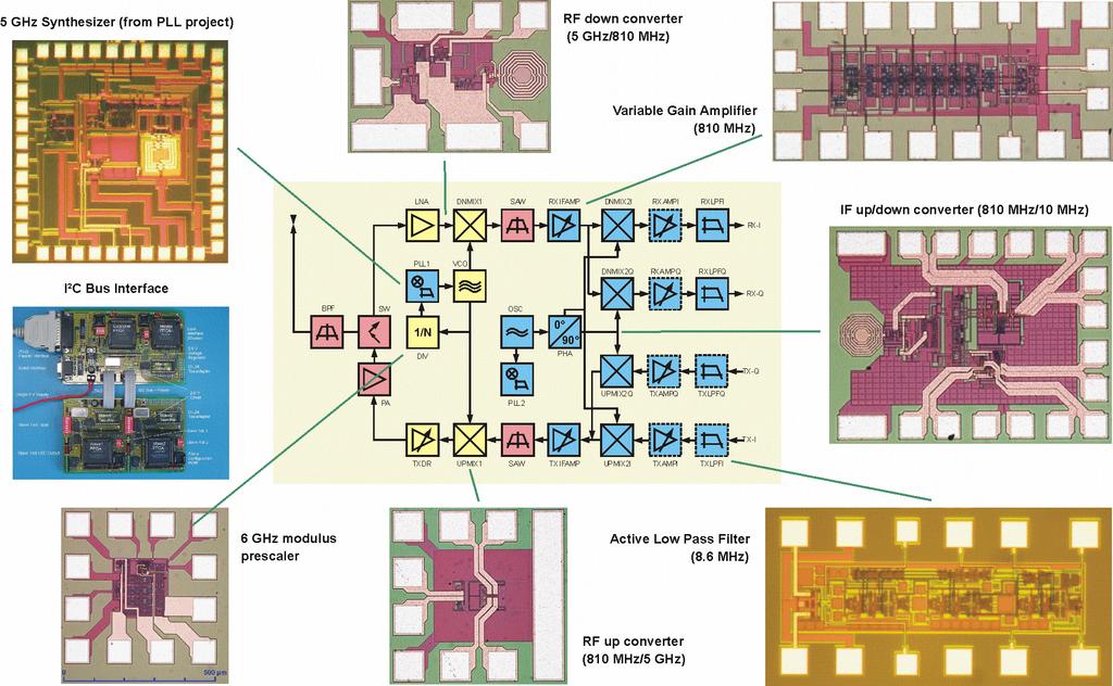
38 5 GHz Analog-Transceiver Blocks
39 Spread spectrum technology Problem of radio transmission: frequency dependent fading can wipe out narrow band signals for duration of the interference Solution: spread the narrow band signal into a broad band signal using a special code power interference spread signal power detection at receiver signal spread interference f f Side effects: coexistence of several signals without dynamic coordination tap-proof Alternatives: Direct Sequence, Frequency Hopping
40 Effects of spreading and interference dp/df dp/df i) dp/df ii) f sender dp/df f user signal broadband interference narrowband interference dp/df iii) iv) v) f receiver f f
41 channel quality Spreading and frequency selective fading narrowband channels frequency narrow band signal guard space channel quality spread spectrum frequency spread spectrum channels By spreading the effect of the fading channel is equally distributed to all users! How can we avoid interference of the chips?
42 DSSS (Direct Sequence Spread Spectrum) I XOR of the signal with pseudo-random number (chipping sequence) many chips per bit (e.g., 128, best known 11) result in higher bandwidth of the Spreading Factor s = t b /t c signal Advantages reduces frequency selective fading in cellular networks base stations can use the same frequency range several base stations can detect and recover the signal soft handover Disadvantages precise power control necessary Precise synchronization necessary (multi correlators can take advantage from multi-path propagation (Rakereceiver) t b 0 1 t c t b : bit period t c : chip period user data XOR chipping sequence = resulting signal
43 DSSS (Direct Sequence Spread Spectrum) II user data X spread spectrum signal modulator transmit signal chipping sequence radio carrier transmitter correlator received signal demodulator lowpass filtered signal X products integrator sampled sums decision data radio carrier chipping sequence receiver
44 Example Barker Code Good autocorrelation properties Minimal sequence allowed by FCC Coding Robust gain against 10.4 time db delay spread
45 FHSS (Frequency Hopping Spread Spectrum) I Discrete changes of carrier frequency sequence of frequency changes determined via pseudo random number sequence Two versions Fast Hopping: several frequencies per user bit Slow Hopping: several user bits per frequency Advantages frequency selective fading and interference limited to short period simple implementation uses only small portion of spectrum at any time Disadvantages not as robust as DSSS simpler to detect
46 FHSS (Frequency Hopping Spread Spectrum) II t b user data f f 3 f 2 f 1 f f 3 f 2 f t d t d t b : bit period t t t t d : dwell time slow Hopping (3 bits/hop) fast Hopping (3 hops/bit) t b <t d t b >t d
47 FHSS (Frequency Hopping Spread Spectrum) III user data modulator narrowband signal modulator spread transmit signal transmitter frequency synthesizer hopping sequence received signal demodulator narrowband signal demodulator data hopping sequence frequency synthesizer receiver
48 Example Bluetooth Frequency Hopping Bluetooth uses a slow frequency hopping scheme The frequency is changed every slot (625 µs) so approximately 1600 hops/s For multi-slot packets the frequency is changed with the next packet The hopping sequence is determined by the master (derived from the bluetooth MAC address) During inquiry and paging the the master MAC and timing offset is exchanged with the slaves The slot are enumerated from 0 to The master uses always the even slot The slot size is 1, 3 or 5
49 Master / Slave Communication B Ma D A C E SCO ACL f(k) f(k+2) f(k+4) f(k+6) f(k+8) f(k+10) f(k+12) f(k+14) f(k+16) f(k+18) f(k+20) f(k+22) f(k+24) A B C D E t SCO 1 ACL SCO 2 ACL SCO 1 ACL SCO 2 ACL SCO 1
50 UWB-System Definition: A signal is considered to be Ultra Wide Band if the Bandwidth of the signal is at least 25 % of the carrier frequency Special definition of FCC: For the UWB-Bands it is sufficient if the channel bandwidth is 500 MHz in the spectrum between 3.1 and 10.6 GHz Currently most systems use narrow band or wide band channels UWB spread the signal power over a very broad band and interferes therefore minimally with existing narrowband/wideband systems Spreading makes the system more stable against fading channel influences More bandwidth allow more data-rate More bandwidth allows more accurate location determination
51 UWB Spectrum FCC ruling permits UWB spectrum overlay Emitted Signal Power GPS PCS Bluetooth, b Cordless Phones Microwave Ovens a -41 dbm/mhz UWB Spectrum Part 15 Limit Frequency (Ghz) 10.6 FCC ruling issued 2/14/2002 after ~4 years of study & public debate FCC believes current ruling is conservative

52 Theoretical Data Rates over Range UWB shows significant throughput potential at at short range
53 What is Ultra Wideband? Radio technology that modulates impulse based waveforms instead of continuous carrier waves Time-domain behavior Frequency-domain behavior Ultrawideband Communication Impulse Modulation time 3 frequency 10 GHz (FCC Min=500Mhz) Narrowband Communication Frequency Modulation GHz
54 Information Modulation Pulse length ~ 200 ps; Energy concentrated in 2 6 GHz band; Voltage swing ~100 mv; Power ~ 10 µw Pulse Position Modulation (PPM) Pulse Amplitude Modulation (PAM) On-Off Keying (OOK) Bi-Phase Modulation (BPSK)
55 Related Standards IEEE : Wireless Personal Area Network (WPAN) IEEE : Bluetooth, 1 Mbps IEEE : WPAN/high rate, 50 Mbps IEEE a: WPAN/Higher rate, 500 Mbps, UWB IEEE c: WPAN Ultra High Data Rates 2-10 Gb/s IEEE : WPAN/low-rate, low-power, mw level, 200 kbps IEEE a: WPAN/low-rate, low-power, distance measurement; UWB
56 TOA (Time of Arrival) & RTD (Round Trip Delay) Three Principles of Positioning TDOA (Time Difference of Arrival) AOA (Angle of arrival)
57 Cell structure Implements space division multiplex: base station covers a certain transmission area (cell) Mobile stations communicate only via the base station Advantages of cell structures: higher capacity, higher number of users less transmission power needed more robust, decentralized base station deals with interference, transmission area etc. locally Problems: fixed network needed for the base stations handover (changing from one cell to another) necessary interference with other cells Cell sizes from some 100 m in cities to, e.g., 35 km on the country side (GSM) - even less for higher frequencies
58 Frequency planning I Frequency reuse only with a certain distance between the base stations Standard model using 7 frequencies: f 3 f 2 f 4 f 5 f 1 f 3 f 2 f 6 f 7 f 4 f 5 f 1 Fixed frequency assignment: certain frequencies are assigned to a certain cell problem: different traffic load in different cells Dynamic frequency assignment: base station chooses frequencies depending on the frequencies already used in neighbor cells more capacity in cells with more traffic assignment can also be based on interference measurements
59 Frequency planning II f 3 f 1 f 2 f 3 f 2 f 1 f 3 f 1 f 2 f 3 f 3 f 2 f 3 f 3 f 1 f 1 f 2 3 cell cluster f 3 f 4 f 2 f 5 f 1 f 3 f 2 f 3 f 2 f 6 f 7 f 7 f 4 f 5 f 1 f 6 f 5 f 3 f 2 7 cell cluster f 2 f 2 f 2 f f 1 3 h f 3 h f 3 h 2 h 2 1 h g h g 3 1 g 3 g 3 f 1 f 1 g 2 g g 2 1 g g cell cluster with 3 sector antennas
60 Cell breathing CDM systems: cell size depends on current load Additional traffic appears as noise to other users If the noise level is too high users drop out of cells
61 Mobile Communications Chapter 3 : Media Access Motivation SDMA, FDMA, TDMA Aloha Reservation schemes Collision avoidance, MACA Polling CDMA SAMA Comparison
62 Motivation Can we apply media access methods from fixed networks? Example CSMA/CD Carrier Sense Multiple Access with Collision Detection send as soon as the medium is free, listen into the medium if a collision occurs (original method in IEEE 802.3) Problems in wireless networks signal strength decreases proportional to the square of the distance the sender would apply CS and CD, but the collisions happen at the receiver it might be the case that a sender cannot hear the collision, i.e., CD does not work furthermore, CS might not work if, e.g., a terminal is hidden
63 Hidden terminals Motivation - hidden and exposed terminals A sends to B, C cannot receive A C wants to send to B, C senses a free medium (CS fails) collision at B, A cannot receive the collision (CD fails) A is hidden for C Exposed terminals A B C B sends to A, C wants to send to another terminal (not A or B) C has to wait, CS signals a medium in use but A is outside the radio range of C, therefore waiting is not necessary C is exposed to B
64 Motivation - near and far terminals Terminals A and B send, C receives signal strength decreases (at least) proportional to the square of the distance the signal of terminal B therefore drowns out A s signal C cannot receive A A B C If C for example was an arbiter for sending rights, terminal B would drown out terminal A already on the physical layer Also severe problem for CDMA-networks - precise power control needed!
65 Access methods SDMA/FDMA/TDMA SDMA (Space Division Multiple Access) segment space into sectors, use directed antennas cell structure MIMO, Beam steering FDMA (Frequency Division Multiple Access) assign a certain frequency to a transmission channel between a sender and a receiver permanent (e.g., radio broadcast), slow hopping (e.g., GSM), fast hopping (FHSS, Frequency Hopping Spread Spectrum) TDMA (Time Division Multiple Access) assign the fixed sending frequency to a transmission channel between a sender and a receiver for a certain amount of time The multiplexing schemes presented in chapter 2 are now used to control medium access!
66 FDD/FDMA - general scheme, example GSM 960 MHz f MHz 915 MHz MHz 200 khz MHz f u = 890 MHz + i*0.2 MHz f d = f u + 45 MHz 1 FDD (frequency division duplex) t
67 TDD/TDMA - general scheme, example DECT 417 µs downlink uplink t 10ms
68 Mechanism random, distributed (no central arbiter), time-multiplex Slotted Aloha additionally uses time-slots, sending must always start at slot boundaries Aloha Aloha/slotted aloha collision sender A sender B sender C Slotted Aloha collision t sender A sender B sender C t
69 Aloha performance
70 Slotted Aloha performance
71 DAMA - Demand Assigned Multiple Access Channel efficiency only 18 % for Aloha, 36 % for Slotted Aloha (assuming Poisson distribution for packet arrival and packet length) Reservation can increase efficiency to 80 % a sender reserves a future time-slot sending within this reserved time-slot is possible without collision reservation also causes higher delays (only in low load situations, the delay jitter increases dramatically in high load situations) typical scheme for satellite links Examples for reservation algorithms: Explicit Reservation according to Roberts (Reservation-ALOHA) Implicit Reservation (PRMA Packet reservation multiple access) Reservation-TDMA
72 Access method DAMA: Explicit Reservation Explicit Reservation (Reservation Aloha): two modes: ALOHA mode for reservation: competition for small reservation slots, collisions possible reserved mode for data transmission within successfully reserved slots (no collisions possible) it is important for all stations to keep the reservation list consistent at any point in time and, therefore, all stations have to synchronize from time to time. (Synchronization intervals strongly dependant on Clock accuracy) collision Aloha reserved Aloha reserved Aloha reserved Aloha t
73 Access method DAMA: PRMA Implicit reservation (PRMA - Packet Reservation MA): a certain number of slots form a frame, frames are repeated stations compete for empty slots according to the slotted aloha principle once a station reserves a slot successfully, this slot is automatically assigned to this station in all following frames as long as the station has data to send competition for this slots starts again as soon as the slot was empty in the last frame reservation ACDABA-F ACDABA-F AC-ABAF- A---BAFD ACEEBAFD frame 1 frame 2 frame 3 frame time-slot A C D A B A F A C A B A A B A F collision at reservation A B A F D attempts frame 5 A C E E B A F D t
74 Access method DAMA: Reservation-TDMA Reservation Time Division Multiple Access every frame consists of N mini-slots and x data-slots every station has its own mini-slot and can reserve up to k data-slots using this mini-slot (i.e. x = N * k). other stations can send data in unused data-slots according to a roundrobin sending scheme (best-effort traffic) N mini-slots N * k data-slots e.g. N=6, k=2 reservations for data-slots other stations can use free data-slots based on a round-robin scheme
75 MACA - collision avoidance MACA (Multiple Access with Collision Avoidance) uses short signaling packets for collision avoidance RTS (request to send): a sender request the right to send from a receiver with a short RTS packet before it sends a data packet CTS (clear to send): the receiver grants the right to send as soon as it is ready to receive Signaling packets contain sender address receiver address packet size Variants of this method can be found in IEEE as DFWMAC (Distributed Foundation Wireless MAC)
76 MACA avoids the problem of hidden terminals A and C want to send to B A sends RTS first C waits after receiving CTS from B MACA examples RTS CTS CTS A B C MACA avoids the problem of exposed terminals B wants to send to A, C to another terminal now C does not have to wait for it cannot receive CTS from A RTS CTS RTS A B C
77 MACA variant: DFWMAC in IEEE sender receiver idle idle ACK RxBusy time-out NAK; RTS wait for ACK packet ready to send; RTS wait for the right to send CTS; data time-out; RTS data; ACK time-out data; NAK wait for data RTS; CTS ACK: positive acknowledgement NAK: negative acknowledgement RxBusy: receiver busy RTS; RxBusy
78 Polling mechanisms If one terminal can be heard by all others, this central terminal (a.k.a. base station) can poll all other terminals according to a certain scheme now all schemes known from fixed networks can be used (typical mainframe - terminal scenario) This scheme is used in in PCF (Point coordination function) mode Example: Randomly Addressed Polling (no unique MAC address required) base station signals readiness to all mobile terminals terminals ready to send can now transmit a random number without collision with the help of CDMA or FDMA (the random number can be seen as dynamic address) the base station now chooses one address for polling from the list of all random numbers (collision if two terminals choose the same address) the base station acknowledges correct packets and continues polling the next terminal this cycle starts again after polling all terminals of the list
79 ISMA (Inhibit Sense Multiple Access) Current state of the medium is signaled via a busy tone the base station signals on the downlink (base station to terminals) if the medium is free or not (using a special signaling frequency) terminals must not send if the medium is busy terminals can access the medium as soon as the busy tone stops the base station signals collisions and successful transmissions via the busy tone and acknowledgements, respectively (media access is not coordinated within this approach) mechanism used, e.g., for CDPD (Cellular Digital Packet Data) (USA, integrated into AMPS)
80 Access method CDMA CDMA (Code Division Multiple Access) all terminals send on the same frequency probably at the same time and can use the whole bandwidth of the transmission channel each sender has a unique random number, the sender XORs the signal with this random number the receiver can tune into this signal if it knows the pseudo random number, tuning is done via a correlation function Disadvantages: higher complexity of a receiver (receiver cannot just listen into the medium and start receiving if there is a signal) all signals should have the same strength at a receiver Advantages: all terminals can use the same frequency, no planning needed huge code space (e.g ) compared to frequency space interferences (e.g. white noise) is not coded forward error correction and encryption can be easily integrated
81 CDMA in theory Sender A sends A d = 1, key A k = (assign: 0 = -1, 1 = +1) sending signal A s = A d * A k = (-1, +1, -1, -1, +1, +1) Sender B sends B d = 0, key B k = (assign: 0 = -1, 1 = +1) sending signal B s = B d * B k = (-1, -1, +1, -1, +1, -1) Both signals superimpose in space interference neglected (noise etc.) A s + B s = (-2, 0, 0, -2, +2, 0) Receiver wants to receive signal from sender A apply key A k bitwise (inner product) A e = (-2, 0, 0, -2, +2, 0) A k = = 6 result greater than 0, therefore, original bit was 1 receiving B B e = (-2, 0, 0, -2, +2, 0) B k = = -6, i.e. 0
82 data A key A key sequence A data key CDMA on signal level I A d A k signal A A s Real systems use much longer keys resulting in a larger distance between single code words in code space.
83 CDMA on signal level II signal A A s data B B d key B key sequence B data key B k signal B B s A s + B s
84 data A CDMA on signal level III A d A s + B s A k (A s + B s ) * A k integrator output comparator output 1 0 1
85 data B CDMA on signal level IV B d A s + B s B k (A s + B s ) * B k integrator output comparator output 1 0 0
86 CDMA on signal level V A s + B s wrong key K (A s + B s ) * K integrator output comparator output (0) (0)?
87 Aloha has only a very low efficiency, CDMA needs complex receivers to be able to receive different senders with individual codes at the same time Idea: use spread spectrum with only one single code (chipping sequence) for spreading for all senders accessing according to aloha sender A sender B SAMA - Spread Aloha Multiple Access narrow band spread the signal e.g. using the chipping sequence ( CDMA without CD ) 1 1 collision send for a shorter period with higher power Problem: find a chipping sequence with good characteristics t
88 Comparison SDMA/TDMA/FDMA/CDMA Approach SDMA TDMA FDMA CDMA Idea Terminals Signal separation segment space into cells/sectors only one terminal can be active in one cell/one sector cell structure, directed antennas segment sending time into disjoint time-slots, demand driven or fixed patterns all terminals are active for short periods of time on the same frequency synchronization in the time domain segment the frequency band into disjoint sub-bands every terminal has its own frequency, uninterrupted filtering in the frequency domain spread the spectrum using orthogonal codes all terminals can be active at the same place at the same moment, uninterrupted code plus special receivers Advantages very simple, increases capacity per km² Disadvantages Comment inflexible, antennas typically fixed only in combination with TDMA, FDMA or CDMA useful established, fully digital, flexible guard space needed (multipath propagation), synchronization difficult standard in fixed networks, together with FDMA/SDMA used in many mobile networks simple, established, robust inflexible, frequencies are a scarce resource typically combined with TDMA (frequency hopping patterns) and SDMA (frequency reuse) flexible, less frequency planning needed, soft handover complex receivers, needs more complicated power control for senders still faces some problems, higher complexity, lowered expectations; will be integrated with TDMA/FDMA
Chapter 2: Wireless Transmission. Mobile Communications. Spread spectrum. Multiplexing. Modulation. Frequencies. Antenna. Signals
 Mobile Communications Chapter 2: Wireless Transmission Frequencies Multiplexing Signals Spread spectrum Antenna Modulation Signal propagation Cellular systems Prof. Dr.-Ing. Jochen Schiller, http://www.jochenschiller.de/
Chapter 3 : Media Access. Mobile Communications. Collision avoidance, MACA
 Mobile Communications Chapter 3 : Media Access Motivation Collision avoidance, MACA SDMA, FDMA, TDMA Polling Aloha CDMA Reservation schemes SAMA Comparison Prof. Dr.-Ing. Jochen Schiller, http://www.jochenschiller.de/
ICT 5305 Mobile Communications. Lecture - 4 April Dr. Hossen Asiful Mustafa
 ICT 5305 Mobile Communications Lecture - 4 April 2016 Dr. Hossen Asiful Mustafa Media Access Motivation Can we apply media access methods from fixed networks? Example CSMA/CD Carrier Sense Multiple Access
Mobile Computing. Chapter 3: Medium Access Control
 Mobile Computing Chapter 3: Medium Access Control Prof. Sang-Jo Yoo Contents Motivation Access methods SDMA/FDMA/TDMA Aloha Other access methods Access method CDMA 2 1. Motivation Can we apply media access
Medium Access Control
 CMPE 477 Wireless and Mobile Networks Medium Access Control Motivation for Wireless MAC SDMA FDMA TDMA CDMA Comparisons CMPE 477 Motivation Can we apply media access methods from fixed networks? Example
Medium Access Control. Wireless Networks: Guevara Noubir. Slides adapted from Mobile Communications by J. Schiller
 Wireless Networks: Medium Access Control Guevara Noubir Slides adapted from Mobile Communications by J. Schiller S200, COM3525 Wireless Networks Lecture 4, Motivation Can we apply media access methods
Wireless Transmission & Media Access
 Wireless Transmission & Media Access Signals and Signal Propagation Multiplexing Modulation Media Access 1 Significant parts of slides are based on original material by Prof. Dr.-Ing. Jochen Schiller,
Medium Access Schemes
 Medium Access Schemes Winter Semester 2010/11 Integrated Communication Systems Group Ilmenau University of Technology Media Access: Motivation The problem: multiple users compete for a common, shared resource
Mobile Communications Chapter 2: Wireless Transmission
 Prof. Dr.-Ing Jochen H. Schiller Inst. of Computer Science Freie Universität Berlin Germany Mobile Communications Chapter 2: Wireless Transmission Frequencies Signals, antennas, signal propagation, MIMO
Mobile Communications Chapter 2: Wireless Transmission
 Mobile Communications Chapter 2: Wireless Transmission Frequencies Signals, antennas, signal propagation, MIMO Multiplexing, Cognitive Radio Spread spectrum, modulation Cellular systems 2.1 Frequencies
Chapter 2 Overview. Duplexing, Multiple Access - 1 -
 Chapter 2 Overview Part 1 (2 weeks ago) Digital Transmission System Frequencies, Spectrum Allocation Radio Propagation and Radio Channels Part 2 (last week) Modulation, Coding, Error Correction Part 3
Wireless Transmission:
 Wireless Transmission: Physical Layer Aspects and Channel Characteristics Frequencies Signals Antenna Signal propagation Multiplexing Modulation Spread spectrum Cellular systems 1 Frequencies for communication
Structure of the Lecture
 Structure of the Lecture Chapter 2 Technical Basics: Layer Methods for Medium Access: Layer 2 Channels in a frequency band Static medium access methods Flexible medium access methods Chapter 3 Wireless
1. Introduction 1.2 Medium Access Control. Prof. JP Hubaux
 1. Introduction 1.2 Medium Access Control Prof. JP Hubaux 1 Modulation and demodulation (reminder) analog baseband digital signal data digital analog 101101001 modulation modulation radio transmitter radio
Mobile & Wireless Networking. Lecture 2: Wireless Transmission (2/2)
") 192620010 Mobile & Wireless Networking Lecture 2: Wireless Transmission (2/2) [Schiller, Section 2.6 & 2.7] [Reader Part 1: OFDM: An architecture for the fourth generation] Geert Heijenk Outline of Lecture
192620010 Mobile & Wireless Networking Lecture 2: Wireless Transmission (2/2) [Schiller, Section 2.6 & 2.7] [Reader Part 1: OFDM: An architecture for the fourth generation] Geert Heijenk Outline of Lecture
Structure of the Lecture
 Structure of the Lecture Chapter 2 Technical Basics: Layer 1 Methods for Medium Access: Layer 2 Representation of digital signals on an analogous medium Signal propagation Characteristics of antennas Chapter
E-716-A Mobile Communications Systems. Lecture #2 Basic Concepts of Wireless Transmission (p1) Instructor: Dr. Ahmad El-Banna
 Instructor: Dr. Ahmad El-Banna") October 2014 Ahmad El-Banna Integrated Technical Education Cluster At AlAmeeria E-716-A Mobile Communications Systems Lecture #2 Basic Concepts of Wireless Transmission (p1) Instructor: Dr. Ahmad El-Banna
October 2014 Ahmad El-Banna Integrated Technical Education Cluster At AlAmeeria E-716-A Mobile Communications Systems Lecture #2 Basic Concepts of Wireless Transmission (p1) Instructor: Dr. Ahmad El-Banna
Mobile Communications
 Mobile Communications Semester B, Mandatory modules, ECTS Units: 3 George Pavlides http://georgepavlides.info Book: Jochen H. Schiller, Mobile Communications Second Edition, Addison- Wesley, Pearson Education
Wireless Transmission in Cellular Networks
 Wireless Transmission in Cellular Networks Frequencies Signal propagation Signal to Interference Ratio Channel capacity (Shannon) Multipath propagation Multiplexing Spatial reuse in cellular systems Antennas
Structure of the Lecture. Radio Waves. Frequencies for Mobile Communication. Frequencies (MHz) and Regulations
 and Regulations") Structure of the Lecture Chapter 2 Technical Basics: Laer Methods for Medium Access: Laer 2 Representation of digital signals on an analogous medium Signal propagation Characteristics of antennas Chapter
Structure of the Lecture Chapter 2 Technical Basics: Laer Methods for Medium Access: Laer 2 Representation of digital signals on an analogous medium Signal propagation Characteristics of antennas Chapter
Chapter 2 Overview - 1 -
 Chapter 2 Overview Part 1 (last week) Digital Transmission System Frequencies, Spectrum Allocation Radio Propagation and Radio Channels Part 2 (today) Modulation, Coding, Error Correction Part 3 (next
Mobile Computing and the IoT Wireless and Mobile Computing. Wireless Signals. George Roussos.
 Mobile Computing and the IoT Wireless and Mobile Computing Wireless Signals George Roussos g.roussos@dcs.bbk.ac.uk Overview Signal characteristics Representing digital information with wireless Transmission
Chapter 2 Overview - 1 -
 Chapter 2 Overview Part 1 (last week) Digital Transmission System Frequencies, Spectrum Allocation Radio Propagation and Radio Channels Part 2 (today) Modulation, Coding, Error Correction Part 3 (next
Introduction to Wireless and Mobile Networking. Hung-Yu Wei g National Taiwan University
 Introduction to Wireless and Mobile Networking Lecture 3: Multiplexing, Multiple Access, and Frequency Reuse Hung-Yu Wei g National Taiwan University Multiplexing/Multiple Access Multiplexing Multiplexing
Vehicle Networks. Wireless communication basics. Univ.-Prof. Dr. Thomas Strang, Dipl.-Inform. Matthias Röckl
 Vehicle Networks Wireless communication basics Univ.-Prof. Dr. Thomas Strang, Dipl.-Inform. Matthias Röckl Outline Wireless Signal Propagation Electro-magnetic waves Signal impairments Attenuation Distortion
Chapter 2 PHYSICAL AND LINK LAYER
 Chapter 2 PHYSICAL AND LINK LAYER Distributed Computing Group Mobile Computing Winter 2005 / 2006 Overview Frequencies Signals Antennas Signal propagation Multiplexing Spread spectrum CDMA Modulation Distributed
ICT 5305 Mobile Communications. Lecture - 3 April Dr. Hossen Asiful Mustafa
 ICT 5305 Mobile Communications Lecture - 3 April 2016 Dr. Hossen Asiul Mustaa Advanced Phase Shit Keying Q BPSK (Binary Phase Shit Keying): bit value 0: sine wave bit value 1: inverted sine wave very simple
Multiple Access Schemes
 Multiple Access Schemes Dr Yousef Dama Faculty of Engineering and Information Technology An-Najah National University 2016-2017 Why Multiple access schemes Multiple access schemes are used to allow many
Access Methods and Spectral Efficiency
 Access Methods and Spectral Efficiency Yousef Dama An-Najah National University Mobile Communications Access methods SDMA/FDMA/TDMA SDMA (Space Division Multiple Access) segment space into sectors, use
COM-405 Mobile Networks. Module A (Part A2) Introduction
 Introduction") COM-405 Mobile Networks Module A (Part A2) Introduction Prof. JP Hubaux http://mobnet.epfl.ch Note: some of the slides of this and other modules and derived from Schiller s book 1 Modulation and demodulation
COM-405 Mobile Networks Module A (Part A2) Introduction Prof. JP Hubaux http://mobnet.epfl.ch Note: some of the slides of this and other modules and derived from Schiller s book 1 Modulation and demodulation
Basics of Wireless and Mobile Communications
 Basics of Wireless and Mobile Communications Wireless Transmission Frequencies Signals Antenna Signal propagation Multiplexing Modulation Spread spectrum Cellular systems Media Access Schemes Motivation
Wireless Networks. Why Wireless Networks? Wireless Local Area Network. Wireless Personal Area Network (WPAN)
") Wireless Networks Why Wireless Networks? rate MBit/s 100.0 10.0 1.0 0.1 0.01 wired terminals WMAN WLAN CORDLESS (CT, DECT) Office Building stationary walking drive Indoor HIPERLAN UMTS CELLULAR (GSM) Outdoor
Wireless Networks Why Wireless Networks? rate MBit/s 100.0 10.0 1.0 0.1 0.01 wired terminals WMAN WLAN CORDLESS (CT, DECT) Office Building stationary walking drive Indoor HIPERLAN UMTS CELLULAR (GSM) Outdoor
Mobile Communication-Systems II: From Cellular to Mobile Services. Prof. Dr.-Ing. Rolf Kraemer Lehrstuhl für Systeme
 Mobile Communication-Systems II: From Cellular to Mobile Services Prof. Dr.-Ing. Rolf Kraemer Lehrstuhl für Systeme Lecture Overview Quick Repetition of Basics GSM: Architecture and Features GPRS: Extended
WIRELESS TRANSMISSION
 COMP 635: WIRELESS NETWORKS WIRELESS TRANSMISSION Jasleen Kaur Fall 205 Outline Frequenc Spectrum Ø Usage and Licensing Signals and Antennas Ø Propagation Characteristics Multipleing Ø Space, Frequenc,
Wireless PHY: Modulation and Demodulation
 Wireless PHY: Modulation and Demodulation Y. Richard Yang 09/6/2012 Outline Admin and recap Frequency domain examples Basic concepts of modulation Amplitude modulation Amplitude demodulation frequency
Chapter 7 Multiple Division Techniques for Traffic Channels
 Introduction to Wireless & Mobile Systems Chapter 7 Multiple Division Techniques for Traffic Channels Outline Introduction Concepts and Models for Multiple Divisions Frequency Division Multiple Access
ISHIK UNIVERSITY Faculty of Science Department of Information Technology Fall Course Name: Wireless Networks
 ISHIK UNIVERSITY Faculty of Science Department of Information Technology 2017-2018 Fall Course Name: Wireless Networks Agenda Lecture 4 Multiple Access Techniques: FDMA, TDMA, SDMA and CDMA 1. Frequency
UNIT 4 Spread Spectrum and Multiple. Access Technique
 UNIT 4 Spread Spectrum and Multiple Access Technique Spread Spectrum lspread spectrumis a communication technique that spreads a narrowband communication signal over a wide range of frequencies for transmission
Cellular systems 02/10/06
 Cellular systems 02/10/06 Cellular systems Implements space division multiplex: base station covers a certain transmission area (cell) Mobile stations communicate only via the base station Cell sizes from
Outline. Wireless PHY: Modulation and Demodulation. Admin. Page 1. G[k] = 1 T. g(t)e j2πk t dt. G[k] = = k L. ) = g L (t)e j2π f k t dt.
![Outline. Wireless PHY: Modulation and Demodulation. Admin. Page 1. G[k] = 1 T. g(t)e j2πk t dt. G[k] = = k L. ) = g L (t)e j2π f k t dt.](/thumbs/89/97558237.jpg "Outline. Wireless PHY: Modulation and Demodulation. Admin. Page 1. G[k] = 1 T. g(t)e j2πk t dt. G[k] = = k L. ) = g L (t)e j2π f k t dt.") Outline Wireless PHY: Modulation and Demodulation Y. Richard Yang Admin and recap Basic concepts o modulation Amplitude modulation Amplitude demodulation requency shiting 9/6/22 2 Admin First assignment
Outline Wireless PHY: Modulation and Demodulation Y. Richard Yang Admin and recap Basic concepts o modulation Amplitude modulation Amplitude demodulation requency shiting 9/6/22 2 Admin First assignment
Outline. Wireless PHY: Modulation and Demodulation. Admin. Page 1. g(t)e j2πk t dt. G[k] = 1 T. G[k] = = k L. ) = g L (t)e j2π f k t dt.
![Outline. Wireless PHY: Modulation and Demodulation. Admin. Page 1. g(t)e j2πk t dt. G[k] = 1 T. G[k] = = k L. ) = g L (t)e j2π f k t dt.](/thumbs/76/74238457.jpg "Outline. Wireless PHY: Modulation and Demodulation. Admin. Page 1. g(t)e j2πk t dt. G[k] = 1 T. G[k] = = k L. ) = g L (t)e j2π f k t dt.") Outline Wireless PHY: Modulation and Demodulation Y. Richard Yang Admin and recap Basic concepts o modulation Amplitude demodulation requency shiting 09/6/202 2 Admin First assignment to be posted by this
Outline Wireless PHY: Modulation and Demodulation Y. Richard Yang Admin and recap Basic concepts o modulation Amplitude demodulation requency shiting 09/6/202 2 Admin First assignment to be posted by this
Multiplexing Module W.tra.2
 Multiplexing Module W.tra.2 Dr.M.Y.Wu@CSE Shanghai Jiaotong University Shanghai, China Dr.W.Shu@ECE University of New Mexico Albuquerque, NM, USA 1 Multiplexing W.tra.2-2 Multiplexing shared medium at
CIS 632 / EEC 687 Mobile Computing. Mobile Communications (for Dummies) Chansu Yu. Contents. Modulation Propagation Spread spectrum
 Chansu Yu. Contents. Modulation Propagation Spread spectrum") CIS 632 / EEC 687 Mobile Computing Mobile Communications (for Dummies) Chansu Yu Contents Modulation Propagation Spread spectrum 2 1 Digital Communication 1 0 digital signal t Want to transform to since
CIS 632 / EEC 687 Mobile Computing Mobile Communications (for Dummies) Chansu Yu Contents Modulation Propagation Spread spectrum 2 1 Digital Communication 1 0 digital signal t Want to transform to since
Mobile Ad Hoc Networks
 Mobile Ad Hoc Networks Dr. Lokesh Chouhan Assistant Professor Computer Science and Engineering (CSE) Department National Institute of Technology (NIT) Hamirpur (H.P.) INDIA Website: http://nith.ac.in/newweb/computer-science-engineering/
Mobile Computing Unit 1 WIRELESS COMMUNICATION FUNDAMENTALS
 WIRELESS COMMUNICATION FUNDAMENTALS Objective Unit I present some basics about wireless transmission technology. The topics covered include: frequencies used for communication, signal characteristics,
UNIT I WIRELESS TRANSMISSION FUNDAMENTALS
 UNIT I WIRELESS TRANSMISSION FUNDAMENTALS Introduction to wireless transmission signal propagation Multiplexing-Modulation-Spread Spectrum-Fading- Coding and Error control. Applications of Wireless Networks
Multiple Access Techniques
 Multiple Access Techniques EE 442 Spring Semester Lecture 13 Multiple Access is the use of multiplexing techniques to provide communication service to multiple users over a single channel. It allows for
Mobile Communication Systems. Part 7- Multiplexing
 Mobile Communication Systems Part 7- Multiplexing Professor Z Ghassemlooy Faculty of Engineering and Environment University of Northumbria U.K. http://soe.ac.uk/ocr Contents Multiple Access Multiplexing
Page 1. Outline : Wireless Networks Lecture 6: Final Physical Layer. Direct Sequence Spread Spectrum (DSSS) Spread Spectrum
 Spread Spectrum") Outline 18-759 : Wireless Networks Lecture 6: Final Physical Layer Peter Steenkiste Dina Papagiannaki Spring Semester 2009 http://www.cs.cmu.edu/~prs/wireless09/ Peter A. Steenkiste 1 RF introduction Modulation
Outline 18-759 : Wireless Networks Lecture 6: Final Physical Layer Peter Steenkiste Dina Papagiannaki Spring Semester 2009 http://www.cs.cmu.edu/~prs/wireless09/ Peter A. Steenkiste 1 RF introduction Modulation
Difference Between. 1. Old connection is broken before a new connection is activated.
 Difference Between Hard handoff Soft handoff 1. Old connection is broken before a new connection is activated. 1. New connection is activated before the old is broken. 2. "break before make" connection
Part 3. Multiple Access Methods. p. 1 ELEC6040 Mobile Radio Communications, Dept. of E.E.E., HKU
 Part 3. Multiple Access Methods p. 1 ELEC6040 Mobile Radio Communications, Dept. of E.E.E., HKU Review of Multiple Access Methods Aim of multiple access To simultaneously support communications between
Wireless Networks (PHY): Design for Diversity
: Design for Diversity") Wireless Networks (PHY): Design for Diversity Y. Richard Yang 9/20/2012 Outline Admin and recap Design for diversity 2 Admin Assignment 1 questions Assignment 1 office hours Thursday 3-4 @ AKW 307A 3 Recap:
Wireless Networks (PHY): Design for Diversity Y. Richard Yang 9/20/2012 Outline Admin and recap Design for diversity 2 Admin Assignment 1 questions Assignment 1 office hours Thursday 3-4 @ AKW 307A 3 Recap:
CS441 Mobile & Wireless Computing Communication Basics
 Department of Computer Science Southern Illinois University Carbondale CS441 Mobile & Wireless Computing Communication Basics Dr. Kemal Akkaya E-mail: kemal@cs.siu.edu Kemal Akkaya Mobile & Wireless Computing
Wireless Transmission Rab Nawaz Jadoon
 Wireless Transmission Rab Nawaz Jadoon DCS Assistant Professor COMSATS IIT, Abbottabad Pakistan COMSATS Institute of Information Technology Mobile Communication Frequency Spectrum Note: The figure shows
Mobile and Ubiquitous Compu3ng. Wireless Signals. George Roussos.
 Mobile and Ubiquitous Compu3ng Wireless Signals George Roussos g.roussos@dcs.bbk.ac.uk Overview Signal characteris3cs Represen3ng digital informa3on with wireless Transmission and propaga3on Accessing
Advanced Computer Networks. Wireless Networks Fundamentals
 Advanced Computer Networks 263 3501 00 Wireless Networks Fundamentals Patrick Stuedi Spring Semester 2014 Oriana Riva, ETH Zürich Course Outline 1. General principles of network design Review of basic
UNIT- 7. Frequencies above 30Mhz tend to travel in straight lines they are limited in their propagation by the curvature of the earth.
 UNIT- 7 Radio wave propagation and propagation models EM waves below 2Mhz tend to travel as ground waves, These wave tend to follow the curvature of the earth and lose strength rapidly as they travel away
Outline / Wireless Networks and Applications Lecture 5: Physical Layer Signal Propagation and Modulation
 Outline 18-452/18-750 Wireless Networks and Applications Lecture 5: Physical Layer Signal Propagation and Modulation Peter Steenkiste Carnegie Mellon University Spring Semester 2017 http://www.cs.cmu.edu/~prs/wirelesss17/
Wireless Communication Fundamentals Feb. 8, 2005
 Wireless Communication Fundamentals Feb. 8, 005 Dr. Chengzhi Li 1 Suggested Reading Chapter Wireless Communications by T. S. Rappaport, 001 (version ) Rayleigh Fading Channels in Mobile Digital Communication
PRINCIPLES OF COMMUNICATION SYSTEMS. Lecture 1- Introduction Elements, Modulation, Demodulation, Frequency Spectrum
 PRINCIPLES OF COMMUNICATION SYSTEMS Lecture 1- Introduction Elements, Modulation, Demodulation, Frequency Spectrum Topic covered Introduction to subject Elements of Communication system Modulation General
Physical Layer: Modulation, FEC. Wireless Networks: Guevara Noubir. S2001, COM3525 Wireless Networks Lecture 3, 1
 Wireless Networks: Physical Layer: Modulation, FEC Guevara Noubir Noubir@ccsneuedu S, COM355 Wireless Networks Lecture 3, Lecture focus Modulation techniques Bit Error Rate Reducing the BER Forward Error
OFDMA and MIMO Notes
 OFDMA and MIMO Notes EE 442 Spring Semester Lecture 14 Orthogonal Frequency Division Multiplexing (OFDM) is a digital multi-carrier modulation technique extending the concept of single subcarrier modulation
 Introduction to Mobile Computing The rapidly expanding technology of cellular communication, wireless LANs, and satellite services will make information accessible anywhere and at any time. Regardless
Multiple Access Techniques for Wireless Communications
 Multiple Access Techniques for Wireless Communications Contents 1. Frequency Division Multiple Access (FDMA) 2. Time Division Multiple Access (TDMA) 3. Code Division Multiple Access (CDMA) 4. Space Division
Chapter 1 Acknowledgment:
 Chapter 1 Acknowledgment: This material is based on the slides formatted by Dr Sunilkumar S. Manvi and Dr Mahabaleshwar S. Kakkasageri, the authors of the textbook: Wireless and Mobile Networks, concepts
Section 1 Wireless Transmission
 Part : Wireless Communication! section : Wireless Transmission! Section : Digital modulation! Section : Multiplexing/Medium Access Control (MAC) Section Wireless Transmission Intro. to Wireless Transmission
EC 551 Telecommunication System Engineering. Mohamed Khedr
 EC 551 Telecommunication System Engineering Mohamed Khedr http://webmail.aast.edu/~khedr 1 Mohamed Khedr., 2008 Syllabus Tentatively Week 1 Week 2 Week 3 Week 4 Week 5 Week 6 Week 7 Week 8 Week 9 Week
Week 2. Topics in Wireless Systems EE584-F 03 9/9/2003. Copyright 2003 Stevens Institute of Technology - All rights reserved
 Week Topics in Wireless Systems 43 0 th Generation Wireless Systems Mobile Telephone Service Few, high-power, long-range basestations -> No sharing of spectrum -> few users -> expensive 44 Cellular Systems
W-CDMA for UMTS Principles
 W-CDMA for UMTS Principles Introduction CDMA Background/ History Code Division Multiple Access (CDMA) Why CDMA? CDMA Principles / Spreading Codes Multi-path Radio Channel and Rake Receiver Problems to
Lecture 3: Wireless Physical Layer: Modulation Techniques. Mythili Vutukuru CS 653 Spring 2014 Jan 13, Monday
 Lecture 3: Wireless Physical Layer: Modulation Techniques Mythili Vutukuru CS 653 Spring 2014 Jan 13, Monday Modulation We saw a simple example of amplitude modulation in the last lecture Modulation how
Point-to-Point Communications
 Point-to-Point Communications Key Aspects of Communication Voice Mail Tones Alphabet Signals Air Paper Media Language English/Hindi English/Hindi Outline of Point-to-Point Communication 1. Signals basic
Simplified Reference Model
 ITCE 720A Autonomic Wireless Networking (Fall, 2009) Mobile Communications Prof. Chansu Yu chansuyu@postech.ac.kr c.yu91@csuohio.edu Simplified Reference Model Mobile Terminals P ro t o c o l S ta c k
SC - Single carrier systems One carrier carries data stream
 Digital modulation SC - Single carrier systems One carrier carries data stream MC - Multi-carrier systems Many carriers are used for data transmission. Data stream is divided into sub-streams and each
An Introduction to Wireless Technologies Part 2. F. Ricci
 An Introduction to Wireless Technologies Part 2 F. Ricci Content Medium access control (MAC): FDMA = Frequency Division Multiple Access TDMA = Time Division Multiple Access CDMA = Code Division Multiple
Wireless Intro : Computer Networking. Wireless Challenges. Overview
 Wireless Intro 15-744: Computer Networking L-17 Wireless Overview TCP on wireless links Wireless MAC Assigned reading [BM09] In Defense of Wireless Carrier Sense [BAB+05] Roofnet (2 sections) Optional
Page 1. Overview : Wireless Networks Lecture 9: OFDM, WiMAX, LTE
 Overview 18-759: Wireless Networks Lecture 9: OFDM, WiMAX, LTE Dina Papagiannaki & Peter Steenkiste Departments of Computer Science and Electrical and Computer Engineering Spring Semester 2009 http://www.cs.cmu.edu/~prs/wireless09/
Ad hoc and Sensor Networks Chapter 4: Physical layer. Holger Karl
 Ad hoc and Sensor Networks Chapter 4: Physical layer Holger Karl Goals of this chapter Get an understanding of the peculiarities of wireless communication Wireless channel as abstraction of these properties
Study on the next generation ITS radio communication in Japan
 Study on the next generation ITS radio communication in Japan DSRC International Task Force, Japan Contents 1. 5.8GHz DSRC in Japan (ARIB STD-T75) 2. Requirements for the next generation ITS radio communication
Multi-carrier Modulation and OFDM
 3/28/2 Multi-carrier Modulation and OFDM Prof. Luiz DaSilva dasilval@tcd.ie +353 896-366 Multi-carrier systems: basic idea Typical mobile radio channel is a fading channel that is flat or frequency selective
Antenna & Propagation. Basic Radio Wave Propagation
 For updated version, please click on http://ocw.ump.edu.my Antenna & Propagation Basic Radio Wave Propagation by Nor Hadzfizah Binti Mohd Radi Faculty of Electric & Electronics Engineering hadzfizah@ump.edu.my
Chapter 7. Multiple Division Techniques
 Chapter 7 Multiple Division Techniques 1 Outline Frequency Division Multiple Access (FDMA) Division Multiple Access (TDMA) Code Division Multiple Access (CDMA) Comparison of FDMA, TDMA, and CDMA Walsh
Wireless Networked Systems. Lec #1b: PHY Basics
 Wireless Networked Systems CS 795/895 - Spring 2013 Lec #1b: PHY Basics Tamer Nadeem Dept. of Computer Science Wireless Communication Page 2 Spring 2013 CS 795/895 - Wireless Networked Systems Radio Signal
Wireless Communications
 2. Physical Layer DIN/CTC/UEM 2018 Periodic Signal Periodic signal: repeats itself in time, that is g(t) = g(t + T ) in which T (given in seconds [s]) is the period of the signal g(t) The number of cycles
Wireless LAN Applications LAN Extension Cross building interconnection Nomadic access Ad hoc networks Single Cell Wireless LAN
 Wireless LANs Mobility Flexibility Hard to wire areas Reduced cost of wireless systems Improved performance of wireless systems Wireless LAN Applications LAN Extension Cross building interconnection Nomadic
Direct Link Communication II: Wireless Media. Current Trend
 Direct Link Communication II: Wireless Media Current Trend WLAN explosion (also called WiFi) took most by surprise cellular telephony: 3G/4G cellular providers/telcos/data in the same mix self-organization
Simple Algorithm in (older) Selection Diversity. Receiver Diversity Can we Do Better? Receiver Diversity Optimization.
 Selection Diversity. Receiver Diversity Can we Do Better? Receiver Diversity Optimization.") 18-452/18-750 Wireless Networks and Applications Lecture 6: Physical Layer Diversity and Coding Peter Steenkiste Carnegie Mellon University Spring Semester 2017 http://www.cs.cmu.edu/~prs/wirelesss17/
18-452/18-750 Wireless Networks and Applications Lecture 6: Physical Layer Diversity and Coding Peter Steenkiste Carnegie Mellon University Spring Semester 2017 http://www.cs.cmu.edu/~prs/wirelesss17/
Wireless data networks Physical Layer
 Wireless data networks Physical Layer Martin Heusse X L ATEX E Attenuation / Propagation Ethernet (twisted pair), attenuation < 10dB for 100m Fiber: typically 1dB/km Radio waves in the air: 10 2 db/km
Wi-Fi. Wireless Fidelity. Spread Spectrum CSMA. Ad-hoc Networks. Engr. Mian Shahzad Iqbal Lecturer Department of Telecommunication Engineering
 Wi-Fi Wireless Fidelity Spread Spectrum CSMA Ad-hoc Networks Engr. Mian Shahzad Iqbal Lecturer Department of Telecommunication Engineering Outline for Today We learned how to setup a WiFi network. This
An Introduction to Wireless Technologies Part 2. F. Ricci 2008/2009
 An Introduction to Wireless Technologies Part 2 F. Ricci 2008/2009 Content Multiplexing Medium access control Medium access control (MAC): FDMA = Frequency Division Multiple Access TDMA = Time Division
Chapter 3. System Theory and Technologies. 3.1 Physical Layer. ... How to transport digital symbols...?
 Chapter 3 System Theory and Technologies 1 r... How to transport digital symbols...? 3.1.1 Introduction 3.1. Symbols, Bits and Baud 3.1.3 Wired Physical Layers 3.1.4 Radio based physical layer electromagnetic
S.D.M COLLEGE OF ENGINEERING AND TECHNOLOGY
 VISHVESHWARAIAH TECHNOLOGICAL UNIVERSITY S.D.M COLLEGE OF ENGINEERING AND TECHNOLOGY A seminar report on Orthogonal Frequency Division Multiplexing (OFDM) Submitted by Sandeep Katakol 2SD06CS085 8th semester
CS263: Wireless Communications and Sensor Networks
 CS263: Wireless Communications and Sensor Networks Matt Welsh Lecture 3: Antennas, Propagation, and Spread Spectrum September 30, 2004 2004 Matt Welsh Harvard University 1 Today's Lecture Antennas and
CS26007:Introduction to Wireless Networking
 CS26007:Introduction to Wireless Networking Guangtao Xue Department of Computer Sciences, Shanghai Jiao Tong University Fall 2015 Course Information Course Information Course #: CS26007 Lecture: T8:55
Technical Aspects of LTE Part I: OFDM
 Technical Aspects of LTE Part I: OFDM By Mohammad Movahhedian, Ph.D., MIET, MIEEE m.movahhedian@mci.ir ITU regional workshop on Long-Term Evolution 9-11 Dec. 2013 Outline Motivation for LTE LTE Network
Level 6 Graduate Diploma in Engineering Wireless and mobile communications
 9210-119 Level 6 Graduate Diploma in Engineering Wireless and mobile communications Sample Paper You should have the following for this examination one answer book non-programmable calculator pen, pencil,
An Introduction to Wireless Technologies Part 1. F. Ricci
 An Introduction to Wireless Technologies Part 1 F. Ricci Content Wireless communication standards Computer Networks Simple reference model Frequencies and regulations Wireless communication technologies
CSC344 Wireless and Mobile Computing. Department of Computer Science COMSATS Institute of Information Technology
 CSC344 Wireless and Mobile Computing Department of Computer Science COMSATS Institute of Information Technology Wireless Physical Layer Concepts Part III Noise Error Detection and Correction Hamming Code
Chapter 4 Radio Communication Basics
 Chapter 4 Radio Communication Basics Chapter 4 Radio Communication Basics RF Spectrum RF Spectrum Infrared (3-400THz): far(3-30), middle(30-120), near(120-400) Visible light (400-800THz) RF: Radio Frequency
Outline. Wireless Networks (PHY): Design for Diversity. Admin. Outline. Page 1. Recap: Impact of Channel on Decisions. [hg(t) + w(t)]g(t)dt.
![Outline. Wireless Networks (PHY): Design for Diversity. Admin. Outline. Page 1. Recap: Impact of Channel on Decisions. [hg(t) + w(t)]g(t)dt.](/thumbs/91/107493207.jpg "Outline. Wireless Networks (PHY): Design for Diversity. Admin. Outline. Page 1. Recap: Impact of Channel on Decisions. [hg(t) + w(t)]g(t)dt.") Wireless Networks (PHY): Design or Diversity Admin and recap Design or diversity Y. Richard Yang 9/2/212 2 Admin Assignment 1 questions Assignment 1 oice hours Thursday 3-4 @ AKW 37A Channel characteristics
Wireless Networks (PHY): Design or Diversity Admin and recap Design or diversity Y. Richard Yang 9/2/212 2 Admin Assignment 1 questions Assignment 1 oice hours Thursday 3-4 @ AKW 37A Channel characteristics
UNIK4230: Mobile Communications. Abul Kaosher
 UNIK4230: Mobile Communications Abul Kaosher abul.kaosher@nsn.com Multiple Access Multiple Access Introduction FDMA (Frequency Division Multiple Access) TDMA (Time Division Multiple Access) CDMA (Code