81195A Optical Modulation Generator Software
|
|
|
- Ann Potter
- 5 years ago
- Views:
Transcription

1 DATA SHEET 81195A Optical Modulation Generator Software Version 1.1
2 Product Description The latest developments in 200G, 400G and 1Tb coherent optical transmission systems are challenging test engineers. More and more flexibility is required to generate clean modulated signals as well as signal impairments to stress coherent receivers over multiple test scenarios. The 81195A optical modulation generator software introduces an innovative soft-waredefined test approach. It enables generation of dual-polarization complex modulated signals as well as elec-tronic synthesis of optical signal impairments such as phase noise, polarization rotation, and polarization mode dispersion (PMD), both in real time with M8195A or in a traditional waveform generation mode using M8195A, M8196A or M8194A Arbitrary waveform generators. Combined with the M8195A 65 GSa/s arbitrary waveform generator hardware Digital Signal Processor functions it improves up to 100x the speed of test, the cost and the predictability of the output In traditional fiber transmission and optical receiver testing, which uses optical elements for stress conditioning, the stress conditions can only be changed in a stochastic way resulting in long test times. In contrast, this new test approach allows you to generate and reproduce dynamic stress conditions with precise time evolution or stress statistics, increasing test coverage and reducing test time. The 81195A software in conjunction with a four-channel Keysight Technologies arbitrary waveform generator can generate cleanand distorted signals. With the digital signal processing (DSP) block of the M8195A, the parameters of the waveform (e.g. the pulse-shaping filter coefficients) and the impairments can be adjusted at run time without downloading a new waveform. The real-time waveform generation enables deterministic emulation of optical signal properties over a long period of time, which previously has not been possible. Key Features Waveform calculation for dual-polarization, complex modulated signals (up to 256QAM) Supporting hardware DSP in M8195A for real-time waveform generation Off-line waveform generation for M8196A, M8194A and multi-module M8195A AWGs setups Effective use of the available M8195A module memory in real-time waveform generation mode for complex modulated signals (up to 8 GSym per channel on two IQ channels simultaneously at up to 32.5 GBaud) Realistic emulation of optical signal properties and impairments, including phase noise, polarization mode dispersion, and polarization rotation over a long period of time Change signal properties, on-the-fly without needing to re-calculate the entire waveform (saves valuable time during debug and characterization) Output triggers synchronized with impairment generation Corresponding analysis capabilities in the Keysight Technologies optical modulation analyzer portfolio Page 2
3 Waveform Creation Methods The 81195A software provides two means of generating waveforms. As shown in the figure below, waveform mode creates them using software algorithms. Real-time mode uses the M8195A hardware DSP block to create the waveforms. Waveform mode Calculates data (e.g. PRBS) Memory (contains waveforms) Ix Qx Calculates encoding, pulse shaping, optical signal properties 81195A software DSP engine (encoding, pulse shaping, optical signal properties) M8195A arbitrary waveform generator Iy Qy Real-time mode Calculates data (e.g. PRBS) Memory (contains symbols) Ix Qx Calculates encoding, pulse shaping, optical signal properties 81195A software DSP engine (encoding, pulse shaping, optical signal properties) M8195A arbitrary waveform generator Iy Qy Each method has distinct benefits: In waveform mode A wide range of baud rates are available (real-time mode is limited to certain ranges) Signal waveforms with non-integer number of samples per symbol can be generated using waveform resampling In real-time mode Signal properties like pulse shaping parameters and signal impairments can be modified at run-time without need for re-calculating and re-downloading a new waveform, significantly reducing test time Real-time operation allows signal property generation and variation, such as polarization rotation, either as fast transients or slowly changing effects over a long period of time Trigger output, which is aligned with the signal impairment pattern, can be used to synchronize test equipment, e.g. time-to-error measurement with BERT Page 3
4 Real Time DSP Engine The real time DSP engine on the AWG chip of the M8195A arbitrary waveform generator consists of a fixed concatenation of pre-defined DSP functions and FIR filters, with programmable coefficients. Coefficient memories of various sizes are available to change the DSP characteristic upon external triggering or according to a repetitive dynamic impairment pattern. Output triggers are generated in sync with the coefficient patterns. External waveform / symbol memory Internal waveform /symbol memory 16 tap FIR AWG ASIC 65 GSa/s FPGA Trigger Hardware encoding and real-time signal property synthesis PSK / QAM encoder PSK / QAM encoder I/Q rotator I/Q rotator Polarization controller PMD emulator Pulse shaper FIR I/Q rotator I/Q rotator Polarization controller Non-linear equalizer 16 tap FIR 16 tap FIR 16 tap FIR 65 GSa/s 65 GSa/s 65 GSa/s Amplifier Outputs Trigger & coefficients Trigger PSK/QAM encoder For the real-time DSP operation, the AWG memory stores the data pattern symbols which are then encoded using the PSK/ QAM encoder based on reconfigurable look-up tables (LUT), instead of storing the pre-calculated waveform samples of the desired signal. IQ rotator The IQ rotator consists of two identical blocks where an instantaneous rotation angle, controlled from a pre-programmed coefficient pattern memory, is applied to the complex IQ signal for both the X and Y polarization, emulating, for example, carrier phase noise or a frequency offset. Polarization controller The polarization controller is a one-tap butterfly filter and alters the state of polarization (SOP) by acting like a concatenation of a circular and linear retarder. Rotation angle and retardation can be controlled from a pre-programmed pattern memory, which allows complex SOP trajectories on the Poincare sphere to be synthesized. PMD emulator Based on the model of multi-segment concatenation of birefringent elements, the PMD emulator block is a complex FIR butterfly structure in which its filter coefficients represent the optical channel s PMD impulse response. Pulse shaper FIR For a spectrally efficient transmission channels, the data symbols can be filtered with a general 16-tap FIR filter to flexibly vary the pulse shaping such as raised or root-raised cosine or the roll-off factor. Non-linear equalizer The non-linear equalizer applies a non-linear transfer function based on a broken line approximation algorithm to the data signal, allowing, for example, the equalizer to compensate for the transfer characteristic of an electro-optical modulator. Page 4
5 Product Structure The product structure of the 81195A optical modulation generator software is divided into Base functionality/waveform mode (does not require any option) Real-time signal processing/real-time mode (requires option #RSP) Optical signal properties (requires option #OSP) In the product description below, features that require one of the options are marked with #RSP or #OSP respectively. The 81195A GUI contains a number of tabs to setup the data pattern, modulation scheme, pulse shaping, and optical signal properties. Supported AWG Setups Support for single module setup (1x M8195A #004 or #002) - waveform mode and real-time mode (#RSP) Support for 4 module setup (4x M8195A #001 with sync module M8197A) in waveform mode only 1 Support for single module M8196A #004 or #002 in waveform mode only 1 Support for single module M8194A #004 or #002 - in waveform mode only 1 Specifications Waveform generation Data source Load external waveform and data patterns (supported formats: CSV, MAT89600 *.mat, *.ptrn) Generate waveforms of the following formats: Standard waveforms (sine, rectangle) Complex modulated (BPSK, QPSK, 8-PSK, 8-QAM (circ.), 16-QAM, 32-QAM, 64-QAM, 128-QAM, 256-QAM) with user-definable constellation rotation angle (phase offset) User-defined constellation 1. RSP functionality is not support for this setup Page 5

6 Symbol rates In Real-time mode: GBaud/ GBaud/ GBaud (i.e. fs/2, fs/4, fs/8 with fs being the sampling rate) In Waveform mode: Arbitrary resampling rates, e.g. 45 GBaud with appropriate pulse shaping Display Constellation plot Transmission rate Data generation PRBS (PRBS7,,PRBS23, PRBS31) selectable per channel Selectable MSB first/lsb first coding Selectable DC-balanced 2^N or standard 2^N-1 PRBS (up to PRBS2^23-1) External pattern file (#OSP) supported format: J-BERT N4903B File *.ptrn per channel Horizontal/Vertical Bit-pattern shift (de-correlation) Display Data pattern length Recommended number of samples Recommended sampling rate (for arbitrary resampling) Page 6
 FIR coefficients can be selected individually for each channel or by single selection for all Display Filter response in time and frequency domain Page")
7 Pulse shaping Pre-defined filter coefficients Rectangular, raised cosine, root-raised cosine, Gaussian Filter roll-off User-defined coefficients (format: CSV) (#OSP) FIR coefficients can be selected individually for each channel or by single selection for all Display Filter response in time and frequency domain Page 7
8 PMD emulation (#OSP) Overview Generally the term polarization mode dispersion (PMD) describes an optical effect that is present when light passes through a concatenation of birefringent elements. It can be represented by a vector, τ,which points in the direction of the system s slow principalstate (PSP), pˆ and its length is the differential group delay (DGD), τ, between the slow and the fast PSP. The PMD vector τ itself is a frequency-dependent parameter and thus should be not mixed up with the mean differential group delay of an optical fiber, which is a statistical scalar value and also often referred to as PMD value in literature. τ ω for 2 ω ω τ. Its parallel component, τ, is The vector difference between two PMD vectors τ ( ω 1 ) and ( ) is defined as second-order PMD (SOPMD) vector, ω ω referred to as polarization-dependent chromatic dispersion (PDCD) and the perpendicular component, τω, as depolarization. Implementation: Emulates standard model of concatenation of birefringent elements with constant length and adjustable axis rotation and output phase. Realized with complex butterfly FIR filter structure 32 GBaud: Up to 7 segments/taps with ps DGD each (at fs = 64 GSa/s) 16 GBaud: Up to 14 segments/taps with ps DGD each (at fs = 64 GSa/s) Load pre-defined states (Zero DGD, minimum pure first order, minimum first order, maximum first order, random) Addressable PMD range (at 64 GSa/s, 32 GBaud) Max. DGD: ps Second-order PMD: > ps² Display Scalar characteristics: PMD, SOPMD, depolarization, PCD Spectral characteristics: DGD, SOPMD s 3 s 3 s 2 p(ω ^ 1 ) s 2 p ^ τ s 1 p(ω ^ 2 ) s 1 τ (ω) Figure 1. PMD vector in Stokes space Figure 2. PSP spectrum τ ω τ (ω) 0 τ ω τ (ω2 ) τ ω τ (ω1 ) ω 1 Frequency ω 2 Figure 3.DGD spectrum Figure 4. Definition of second-order PMD (SOPMD) vector Page 8


9 Figure 5. Addressable PMD space with DSP emulator (shown exemplary states) Page 9

10 Phase Noise (#OSP) Overview The phase noise emulation tab allows artificial phase noise to be added to the waveform thus emulating laser phase noise/jitter and/or a frequency offset by rotating a complex IQ pair. The calculation of the phase noise pattern is based on a laser phase noise model considering three contributions to the phase noise PSD. For details see paper: Narrow Linewidth CW Laser Phase Noise Characterization Methods for Coherent Transmission System Applications, S. Camatel, V. Ferrero, Journal of Lightwave Technology, Vol. 26, No. 17, Sept Details Static frequency offset Range: 2.9 to +2.9 GHz Pattern rotation Generate random phase noise pattern (parameter: linewidth, flicker noise, random walk noise) Upload user-defined pattern (max. length 1024) Pattern advanced rate: 7.6 khz to 500 MHz at 64 GSa/s Display Noise spectrum Example: For an advanced rate of 500 MHz, a phase noise spectrum is generated covering approximately three frequency decades ranging from 500 khz to 250 MHz. Page 10
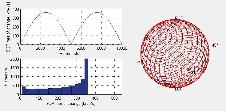
11 Polarization rotation (#OSP) Static and dynamic polarization control Static polarization control Basic mode 2 linear retarders 2 circular retarders Advanced mode 2 complex Jones matrices Dynamic polarization patterns Based on linear/circular retarders Pre-defined pattern modes with adjustable pattern length and SOP change rate characteristics Great circle Spinning coin Slicer Upload of user-defined pattern (max. length 10240) Pattern advanced rate: 1.9 khz to 500 MHz at 64 GSa/s Display SOP trajectory Speed characteristics (SOP pattern, SOP change rate histogram) Page 11
12 Details The SOP rate of change is defined by the pattern type (great circle, slicer, spinning coin), the pattern length as well as the pattern play rate. Therefore, a broad range of SOP rates can be achieved by different combinations of these parameters. At the same time, the maximum SOP angular step between two pattern entries is determined by the total pattern length. Large pattern lengths are used for small angular steps. Once a suitable angular step size has been selected, the speed setting is used to adjust the SOP rate of change and, at the same time, the pattern play time. Example (great circle, 64 GSa/s): Pattern length: SOP angular step: steps SOP rate of change: 3.3 rad/s to 870 krad/s While the great circle pattern gives a constant 2 SOP rate of change in a given plane in stokes space, Spinning Coin mode allows for an almost constant SOP rate of change, while providing good coverage of the Poincaré sphere. The Slicer mode, on the other hand combines sphere coverage with varying rates of change. In Dynamic mode (Pattern mode) and in Basic Static mode, polarization rotation is defined by means of two subsequent stages of both a circular and a linear (H/V) retarder. Each of the retarders covers a range of retardation of 360 at 0.25 step size. An output trigger can be configured which sends a trigger signal at the start of the rotation pattern. This can be used to start error counting in BERT or the DUT and identify the exact SOP when bit errors or system outage occur. Note: When using PMD emulation together with polarization rotation emulation, two individual polarization control stages are available (one before and one after the PMD emulation stage) with reduced pattern capabilities. 2. The pattern will still advance in discrete steps, so the pattern parameters should be chosen for sufficiently small SOP steps. Page 12
")

13 Great circle mode (example) Spinning coin mode (example) Slicer mode (example) Page 13
 Upload of pre-defined patterns: Linear (transparent) Sine ArcSin (inverse EO-modulator characteristic) User function (#OSP) Upload user-defined pattern (supported format: CSV) Display")
14 Non-linear equalizer Individually per channel: Selectable transfer function (broken line approximation with max. 16 segments) Upload of pre-defined patterns: Linear (transparent) Sine ArcSin (inverse EO-modulator characteristic) User function (#OSP) Upload user-defined pattern (supported format: CSV) Display Transfer function Corrections De-embedding of AWG channel specific frequency and phase response Cable loss (standard cable) Skew Gain imbalance VSA equalizer characteristics S-parameter files Real-time mode (#RSP) Correction done by FIR filter in hardware DSP Automatic coefficient calculation based on above de-embedding settings Upload user-defined coefficients (supported format: CSV) Page 14

15 Miscellaneous Clock configuration (internal/external) Channel mapping matrix: Waveform mode: User-defined assignment of XI, XQ, YI, YQ to AWG channels 1 4 Real-time mode: Fixed XI&CH1, XQ&CH2, YI&CH3, YQ&CH4 AWG output amplitude, offset Trigger setup Trigger-in configuration Trigger-out configuration Remote control Remote programming of the optical modulation generator functionality via SCPI interface In Real-time mode DSP coefficient memories are accessible via remote commands to allow for advanced programming Page 15
 Optical signal properties Learn more at: www.keysight.")
16 System Requirements 4 GB memory 10 GB hard disk space Ordering Information 81195A 81195A Opt. RSP 81195A Opt. OSP Optical modulation generator software Real-time signal processing (supported on M8195A #004 or #002 only) Optical signal properties Learn more at: For more information on Keysight Technologies products, applications or services, please contact your local Keysight office. The complete list is available at: Page 16 This information is subject to change without notice. Keysight Technologies, 2018, Published in USA, November 30, 2018, EN
Keysight 81195A Optical Modulation Generator Software
 Keysight 81195A Optical Modulation Generator Software Data Sheet Version 1.1 02 Keysight 81195A Optical Modulation Generator Software - Data Sheet Product Description The latest developments in 200G, 400G
M8195A 65 GSa/s Arbitrary Waveform Generator
 Arbitrary Waveform Generator New AWG with the highest combination of speed, bandwidth and channel density Juergen Beck Vice President & General Mgr. Digital & Photonic Test Division September 10, 2014
M8194A 120 GSa/s Arbitrary Waveform Generator
 M8194A 120 GSa/s Arbitrary Waveform Generator Version 0.9 M8194A in a 2-slot AXIe chassis Find us at www.keysight.com Page 1 M8194A at a glance The Keysight Technologies, Inc. M8194A arbitrary waveform
Polarization Optimized PMD Source Applications
 PMD mitigation in 40Gb/s systems Polarization Optimized PMD Source Applications As the bit rate of fiber optic communication systems increases from 10 Gbps to 40Gbps, 100 Gbps, and beyond, polarization
Fundamentals of Arbitrary. Waveform Generation
 Fundamentals of Arbitrary Waveform Generation History Applications Key Specifications Optimization Signal fidelity and dynamic range Embedding and de-embedding Waveform generation and automation software
PSO-200 OPTICAL MODULATION ANALYZER
 PSO-200 OPTICAL MODULATION ANALYZER Future-proof characterization of any optical signal SPEC SHEET KEY FEATURES All-optical design providing the effective bandwidth to properly characterize waveforms and
Keysight Technologies Characterizing High-Speed Coherent Optical Transmission Systems
 Keysight Technologies Characterizing High-Speed Coherent Optical Transmission Systems Application Brief M8195A 65 GSa/s Arbitrary Waveform Generator N4391A Optical Modulation Analyzer & N4392A Integrated
Lecture 7 Fiber Optical Communication Lecture 7, Slide 1
 Dispersion management Lecture 7 Dispersion compensating fibers (DCF) Fiber Bragg gratings (FBG) Dispersion-equalizing filters Optical phase conjugation (OPC) Electronic dispersion compensation (EDC) Fiber
NOW WITH UP TO 40 GHz BANDWIDTH
 NOW WITH UP TO 40 GHz BANDWIDTH IQTransmitter Industry Leading High Bandwidth of 40 GHz Full & Emulated Dual-Polarization IQTransmitter Your choice of 40 GHz, 26 GHz or 11 GHz of bandwidth Pattern independent
Improving Amplitude Accuracy with Next-Generation Signal Generators
 Improving Amplitude Accuracy with Next-Generation Signal Generators Generate True Performance Signal generators offer precise and highly stable test signals for a variety of components and systems test
Polarization Mode Dispersion and Its Mitigation Techniques in High Speed Fiber Optical Communication Systems
 Polarization Mode Dispersion and Its Mitigation Techniques in High Speed Fiber Optical Communication Systems Chongjin Xie Bell Labs, Lucent Technologies 791 Holmdel-Keyport Road, Holmdel, NJ 07733 WOCC
Keysight Technologies M8196A 92 GSa/s Arbitrary Waveform Generator
 Keysight Technologies M8196A 92 GSa/s Arbitrary Waveform Generator Data Sheet Version 2.1 M8196A in a 2-slot AXIe chassis 02 Keysight M8196A 92 GSa/s Arbitrary Waveform Generator - Data Sheet M8196A at
SHF BERT, DAC & Transmitter for Arbitrary Waveform Generation & Optical Transmission
 SHF BERT, DAC & Transmitter for Arbitrary Waveform Generation & Optical Transmission SHF reserves the right to change specifications and design without notice SHF BERT V017 Jan., 017 Page 1/8 All new BPG
OFDM for Optical Communications
 OFDM for Optical Communications William Shieh Department of Electrical and Electronic Engineering The University of Melbourne Ivan Djordjevic Department of Electrical and Computer Engineering The University
Next-Generation Optical Fiber Network Communication
 Next-Generation Optical Fiber Network Communication Naveen Panwar; Pankaj Kumar & manupanwar46@gmail.com & chandra.pankaj30@gmail.com ABSTRACT: In all over the world, much higher order off modulation formats
SHF BERT & DAC for NRZ, PAM4 and Arbitrary Waveform Generation
 SHF BERT & DAC for NRZ, PAM4 and Arbitrary Waveform Generation Content SHF s one for all System 2 (a) 64 or 120 Gbps binary NRZ BERT 2 (b) 60 GSymbols/s AWG 3 (c) 60 GBaud PAM4 Generator and Analyzer (PAM4-BERT)
Making Noise in RF Receivers Simulate Real-World Signals with Signal Generators
 Making Noise in RF Receivers Simulate Real-World Signals with Signal Generators Noise is an unwanted signal. In communication systems, noise affects both transmitter and receiver performance. It degrades
Study the Effects and Compensation of Polarization Mode Dispersion (PMD) at Different Bit Rates
 at Different Bit Rates") IOSR Journal of Engineering (IOSRJEN) ISSN: 2250-3021 Volume 2, Issue 7(July 2012), PP 32-40 Study the Effects and Compensation of Polarization Mode Dispersion (PMD) at Different Bit Rates Kapil Kashyap
IOSR Journal of Engineering (IOSRJEN) ISSN: 2250-3021 Volume 2, Issue 7(July 2012), PP 32-40 Study the Effects and Compensation of Polarization Mode Dispersion (PMD) at Different Bit Rates Kapil Kashyap
9 Best Practices for Optimizing Your Signal Generator Part 2 Making Better Measurements
 9 Best Practices for Optimizing Your Signal Generator Part 2 Making Better Measurements In consumer wireless, military communications, or radar, you face an ongoing bandwidth crunch in a spectrum that
L évolution des systèmes de transmission optique très haut débit et l impact de la photonique sur silicium
 L évolution des systèmes de transmission optique très haut débit et l impact de la photonique sur silicium G. Charlet 27-November-2017 1 Introduction Evolution of long distance transmission systems: from
PGT313 Digital Communication Technology. Lab 3. Quadrature Phase Shift Keying (QPSK) and 8-Phase Shift Keying (8-PSK)
 and 8-Phase Shift Keying (8-PSK)") PGT313 Digital Communication Technology Lab 3 Quadrature Phase Shift Keying (QPSK) and 8-Phase Shift Keying (8-PSK) Objectives i) To study the digitally modulated quadrature phase shift keying (QPSK) and
PGT313 Digital Communication Technology Lab 3 Quadrature Phase Shift Keying (QPSK) and 8-Phase Shift Keying (8-PSK) Objectives i) To study the digitally modulated quadrature phase shift keying (QPSK) and
SHF Communication Technologies AG
 SHF Communication Technologies AG Wilhelm-von-Siemens-Str. 23D 12277 Berlin Germany Phone ++49 30 / 772 05 10 Fax ++49 30 / 753 10 78 E-Mail: sales@shf.de Web: http://www.shf.de Datasheet SHF 46215 B Optical
46 GBaud Multi-Format Optical Transmitter OM5110 Datasheet
 46 GBaud Multi-Format Optical Transmitter OM5110 Datasheet The OM5110 Multi-Format Optical Transmitter is a C-and L-Band transmitter capable of providing the most common coherent optical modulation formats
Keysight Technologies 81180B Arbitrary Waveform Generator
 Ihr Spezialist für Mess- und Prüfgeräte Keysight Technologies 81180B Arbitrary Waveform Generator Data Sheet Set up complex real-world signals with up to 4.6-GSa/s arbitrary waveforms and 12-bit vertical
Keysight Technologies M8196A 92 GSa/s Arbitrary Waveform Generator
 Keysight Technologies M8196A 92 GSa/s Arbitrary Waveform Generator Data Sheet M8196A in a 2-slot AXIe chassis 02 Keysight M8196A 92 GSa/s Arbitrary Waveform Generator - Data Sheet M8196A at a Glance The
Lecture 2 Fiber Optical Communication Lecture 2, Slide 1
 Lecture 2 General concepts Digital modulation in general Optical modulation Direct modulation External modulation Modulation formats Differential detection Coherent detection Fiber Optical Communication
Global Consumer Internet Traffic
 Evolving Optical Transport Networks to 100G Lambdas and Beyond Gaylord Hart Infinera Abstract The cable industry is beginning to migrate to 100G core optical transport waves, which greatly improve fiber
HP 8509B Lightwave Polarization Analyzer. Product Overview. Optical polarization measurements of signal and components nm to 1600 nm
 HP 8509B Lightwave Polarization Analyzer Product Overview polarization measurements of signal and components 1200 nm to 1600 nm 2 The HP 8509B Lightwave Polarization Analyzer The HP 8509B lightwave polarization
Mike Harrop September PMD Testing in modern networks
 Mike Harrop Mike.harrop@exfo.com September 2016 PMD Testing in modern networks Table of Contents 1 Quick review of PMD 2 Impacts & limits 3 Impact of coherent systems 4 Challenges/Reducing the risk 5 Solutions
[P6] Naser Tarhuni, Timo O. Korhonen, and Mohammed Elmusrati, "State of Polarization Encoding for Optical Code Division Multiple Access Networks,"
![[P6] Naser Tarhuni, Timo O. Korhonen, and Mohammed Elmusrati, State of Polarization Encoding for Optical Code Division Multiple Access Networks,](/thumbs/89/98268029.jpg "[P6] Naser Tarhuni, Timo O. Korhonen, and Mohammed Elmusrati, State of Polarization Encoding for Optical Code Division Multiple Access Networks,") [P6] Naser Tarhuni, Timo O. Korhonen, and Mohammed Elmusrati, "State of Polarization Encoding for Optical Code Division Multiple Access Networks," Journal of ElectroMagnetic Waves and Applications JEMWA
[P6] Naser Tarhuni, Timo O. Korhonen, and Mohammed Elmusrati, "State of Polarization Encoding for Optical Code Division Multiple Access Networks," Journal of ElectroMagnetic Waves and Applications JEMWA
Digital Signal Processing. VO Embedded Systems Engineering Armin Wasicek WS 2009/10
 Digital Signal Processing VO Embedded Systems Engineering Armin Wasicek WS 2009/10 Overview Signals and Systems Processing of Signals Display of Signals Digital Signal Processors Common Signal Processing
Keysight Technologies M8290A Optical Modulation Analyzer and High-Speed Digitizer Test Solution. Data Sheet
 Keysight Technologies M8290A Optical Modulation Analyzer and High-Speed Digitizer Test Solution Data Sheet 02 Keysight M8290A Optical Modulation and High-Speed Digitizer Test Solution - Data Sheet Table
Performance Analysis Of Hybrid Optical OFDM System With High Order Dispersion Compensation
 Performance Analysis Of Hybrid Optical OFDM System With High Order Dispersion Compensation Manpreet Singh Student, University College of Engineering, Punjabi University, Patiala, India. Abstract Orthogonal
Simulating and Testing of Signal Processing Methods for Frequency Stepped Chirp Radar
 Test & Measurement Simulating and Testing of Signal Processing Methods for Frequency Stepped Chirp Radar Modern radar systems serve a broad range of commercial, civil, scientific and military applications.
Testing with Femtosecond Pulses
 Testing with Femtosecond Pulses White Paper PN 200-0200-00 Revision 1.3 January 2009 Calmar Laser, Inc www.calmarlaser.com Overview Calmar s femtosecond laser sources are passively mode-locked fiber lasers.
END-OF-YEAR EXAMINATIONS ELEC321 Communication Systems (D2) Tuesday, 22 November 2005, 9:20 a.m. Three hours plus 10 minutes reading time.
 Tuesday, 22 November 2005, 9:20 a.m. Three hours plus 10 minutes reading time.") END-OF-YEAR EXAMINATIONS 2005 Unit: Day and Time: Time Allowed: ELEC321 Communication Systems (D2) Tuesday, 22 November 2005, 9:20 a.m. Three hours plus 10 minutes reading time. Total Number of Questions:
END-OF-YEAR EXAMINATIONS 2005 Unit: Day and Time: Time Allowed: ELEC321 Communication Systems (D2) Tuesday, 22 November 2005, 9:20 a.m. Three hours plus 10 minutes reading time. Total Number of Questions:
Baseline Proposal for 400G/80km. Ilya Lyubomirsky, Jamal Riani, Ben Smith, Sudeep Bhoja, Inphi Corp. Rich Baca, Microsoft Corp.
 Baseline Proposal for 400G/80km Ilya Lyubomirsky, Jamal Riani, Ben Smith, Sudeep Bhoja, Inphi Corp. Rich Baca, Microsoft Corp. IEEE P802.3cn Task Force Meeting, Nov. 12-13, 2018 Supporters Brad Booth,
Keysight Technologies N4392A Optical Modulation Analyzer Compact, Portable, Affordable
 Keysight Technologies N4392A Optical Modulation Analyzer Compact, Portable, Affordable Data Sheet Your personal test tool for complex modulated optical signals 02 Keysight N4392A Optical Modulation Analyzer
Addressing the Challenges of Wideband Radar Signal Generation and Analysis. Marco Vivarelli Digital Sales Specialist
 Addressing the Challenges of Wideband Radar Signal Generation and Analysis Marco Vivarelli Digital Sales Specialist Agenda Challenges of Wideband Signal Generation Challenges of Wideband Signal Analysis
Testing RFIC Power Amplifiers with Envelope Tracking. April 2014
 Testing RFIC Power Amplifiers with Envelope Tracking April 2014 1 Agenda Key Test Challenges Addressing Test Challenges New emerging technologies such as envelope tracking and DPD and their implications
Keysight 81199A Wideband Waveform Center. Data Sheet
 Keysight 81199A Wideband Waveform Center Data Sheet Overview The trend continues: Increasingly convenient wireless access is driving demand for more data in less time. As transmission rates climb, it puts
Lecture 3: Wireless Physical Layer: Modulation Techniques. Mythili Vutukuru CS 653 Spring 2014 Jan 13, Monday
 Lecture 3: Wireless Physical Layer: Modulation Techniques Mythili Vutukuru CS 653 Spring 2014 Jan 13, Monday Modulation We saw a simple example of amplitude modulation in the last lecture Modulation how
Phase Modulator for Higher Order Dispersion Compensation in Optical OFDM System
 Phase Modulator for Higher Order Dispersion Compensation in Optical OFDM System Manpreet Singh 1, Karamjit Kaur 2 Student, University College of Engineering, Punjabi University, Patiala, India 1. Assistant
Emerging Subsea Networks
 Optimization of Pulse Shaping Scheme and Multiplexing/Demultiplexing Configuration for Ultra-Dense WDM based on mqam Modulation Format Takanori Inoue, Yoshihisa Inada, Eduardo Mateo, Takaaki Ogata (NEC
Unprecedented wealth of signals for virtually any requirement
 Dual-Channel Arbitrary / Function Generator R&S AM300 Unprecedented wealth of signals for virtually any requirement The new Dual-Channel Arbitrary / Function Generator R&S AM300 ideally complements the
Keysight Technologies Pulsed Antenna Measurements Using PNA Network Analyzers
 Keysight Technologies Pulsed Antenna Measurements Using PNA Network Analyzers White Paper Abstract This paper presents advances in the instrumentation techniques that can be used for the measurement and
SHF Communication Technologies AG. Wilhelm-von-Siemens-Str. 23D Berlin Germany. Phone Fax
 SHF Communication Technologies AG Wilhelm-von-Siemens-Str. 23D 12277 Berlin Germany Phone +49 30 772051-0 Fax ++49 30 7531078 E-Mail: sales@shf.de Web: http://www.shf.de Application Note Jitter Injection
CodeSScientific. OCSim Modules 2018 version 2.0. Fiber Optic Communication System Simulations Software Modules with Matlab
 CodeSScientific OCSim Modules 2018 version 2.0 Fiber Optic Communication System Simulations Software Modules with Matlab Use the Existing Modules for Research Papers, Research Projects and Theses Modify
Using a design-to-test capability for LTE MIMO (Part 1 of 2)
") Using a design-to-test capability for LTE MIMO (Part 1 of 2) System-level simulation helps engineers gain valuable insight into the design sensitivities of Long Term Evolution (LTE) Multiple-Input Multiple-Output
Using a design-to-test capability for LTE MIMO (Part 1 of 2) System-level simulation helps engineers gain valuable insight into the design sensitivities of Long Term Evolution (LTE) Multiple-Input Multiple-Output
Real-Time Digital Down-Conversion with Equalization
 Real-Time Digital Down-Conversion with Equalization February 20, 2019 By Alexander Taratorin, Anatoli Stein, Valeriy Serebryanskiy and Lauri Viitas DOWN CONVERSION PRINCIPLE Down conversion is basic operation
40 Gb/s and 100 Gb/s Ultra Long Haul Submarine Systems
 4 Gb/s and 1 Gb/s Ultra Long Haul Submarine Systems Jamie Gaudette, John Sitch, Mark Hinds, Elizabeth Rivera Hartling, Phil Rolle, Robert Hadaway, Kim Roberts [Nortel], Brian Smith, Dean Veverka [Southern
Keysight Technologies, Inc. Overcome PCB Loss and Deliver a Clean Eye to Your DUT Using Multi-tap De-emphasis
 Keysight Technologies, Inc. Overcome PCB Loss and Deliver a Clean Eye to Your DUT Using Multi-tap De-emphasis Application Brief Introduction Keysight Technologies, Inc. announces a new 32 Gb/s pattern
Key Features for OptiSystem 14.2
 14.2 New Features Created to address the needs of research scientists, photonic engineers, professors and students; OptiSystem satisfies the demand of users who are searching for a powerful yet easy to
M8131A 16/32 GSa/s Digitizer
 M8131A 16/32 GSa/s Digitizer Preliminary Data Sheet, Version 0.6, April 10 th, 2019 Find us at www.keysight.com Page 1 M8131A at a glance Key features 10 bit ADC 1, 2 or 4 channels, 6.5 GHz bandwidth (16
Payload measurements with digital signals. Markus Lörner, Product Management Signal Generation Dr. Susanne Hirschmann, Signal Processing Development
 Payload measurements with digital signals Markus Lörner, Product Management Signal Generation Dr. Susanne Hirschmann, Signal Processing Development Agenda ı Why test with modulated signals? ı Test environment
IZT C6000 RF Link Emulator
 www.izt-labs.de IZT C6000 RF Link Emulator Bi-directional wideband solutions for up to 600 MHz bandwidth Simulation of complete satellite links including payload, uplink and downlink effects Simulation
Polarization Related Tests for Coherent Detection Systems
 INTRODUCTION Coherent detection with polarization division multiplexing (PDM) has emerged as the key technology enabler for 40 Gbps and 100 Gbps networks because it significantly increases the spectral
Key Critical Specs You Should Know Before Selecting a Function Generator
 W H I T E PA P E R Key Critical Specs You Should Know Before Selecting a Function Generator Selecting a benchtop function generator for your everyday use is very important. You want to be sure it produces
Arbitrary/Function Waveform Generators 4075B Series
 Data Sheet Arbitrary/Function Waveform Generators Point-by-Point Signal Integrity The Arbitrary/Function Waveform Generators are versatile high-performance single- and dual-channel arbitrary waveform generators
Advanced RF Measurements You Didn t Know Your Oscilloscope Could Make. Brad Frieden Philip Gresock
 Advanced RF Measurements You Didn t Know Your Oscilloscope Could Make Brad Frieden Philip Gresock Agenda RF measurement challenges Oscilloscope platform overview Typical RF characteristics Bandwidth vs.
VIAVI Signal Workshop
 Data Sheet VIAVI Signal Workshop Configurable Modular Platform Introduction/Overview Signal Workshop is a fully integrated waveform creation, generation, signal capture, and post-capture analysis software
Keysight Technologies The ABC s of Arbitrary Waveform Generation. Application Note
 Keysight Technologies The ABC s of Arbitrary Waveform Generation Application Note Introduction Signal simulation In the old days, signal generation was fairly straight-forward. Analog signals were generated
Keysight Technologies
 Keysight Technologies 65 GSa/s Arbitrary Waveform Generator M8197A Multi-Channel Synchronization Module Data Sheet Version 3.1 02 Keysight 65 GSa/s Arbitrary Waveform Generator and M8197A Multi-Channel
The Fundamentals of Mixed Signal Testing
 The Fundamentals of Mixed Signal Testing Course Information The Fundamentals of Mixed Signal Testing course is designed to provide the foundation of knowledge that is required for testing modern mixed
Exploring Trends in Technology and Testing in Satellite Communications
 Exploring Trends in Technology and Testing in Satellite Communications Aerospace Defense Symposium Giuseppe Savoia Keysight Technologies Agenda Page 2 Evolving military and commercial satellite communications
Single channel and WDM transmission of 28 Gbaud zero-guard-interval CO-OFDM
 Single channel and WDM transmission of 28 Gbaud zero-guard-interval CO-OFDM Qunbi Zhuge, * Mohamed Morsy-Osman, Mohammad E. Mousa-Pasandi, Xian Xu, Mathieu Chagnon, Ziad A. El-Sahn, Chen Chen, and David
Antenna Measurements using Modulated Signals
 Antenna Measurements using Modulated Signals Roger Dygert MI Technologies, 1125 Satellite Boulevard, Suite 100 Suwanee, GA 30024-4629 Abstract Antenna test engineers are faced with testing increasingly
Keysight Technologies 81180B Arbitrary Waveform Generator
 Keysight Technologies 81180B Arbitrary Waveform Generator Data Sheet Set up complex real-world signals with up to 4.6-GSa/s arbitrary waveforms and 12-bit vertical resolution 02 Keysight 81180B Arbitrary
Optical Measurements in 100 and 400 Gb/s Networks: Will Coherent Receivers Take Over? Fred Heismann
 Optical Measurements in 100 and 400 Gb/s Networks: Will Coherent Receivers Take Over? Fred Heismann Chief Scientist Fiberoptic Test & Measurement Key Trends in DWDM and Impact on Test & Measurement Complex
Lab 2: Digital Modulations
 Lab 2: Digital Modulations Due: November 1, 2018 In this lab you will use a hardware device (RTL-SDR which has a frequency range of 25 MHz 1.75 GHz) to implement a digital receiver with Quaternary Phase
Fundamentals of Radar Measurements. Primer
 Primer Table of Contents Chapter I. Introduction.........................1 Radar Measurement Tasks Through the life cycle of a radar system.............................1 Challenges of Radar Design & Verification..............1
Application Note. StarMIMO. RX Diversity and MIMO OTA Test Range
 Application Note StarMIMO RX Diversity and MIMO OTA Test Range Contents Introduction P. 03 StarMIMO setup P. 04 1/ Multi-probe technology P. 05 Cluster vs Multiple Cluster setups Volume vs Number of probes
Picking the Optimal Oscilloscope for Serial Data Signal Integrity Validation and Debug
 Picking the Optimal Oscilloscope for Serial Data Signal Integrity Validation and Debug Application Note 1556 Introduction In the past, it was easy to decide whether to use a real-time oscilloscope or an
Modern Quadrature Amplitude Modulation Principles and Applications for Fixed and Wireless Channels
 1 Modern Quadrature Amplitude Modulation Principles and Applications for Fixed and Wireless Channels W.T. Webb, L.Hanzo Contents PART I: Background to QAM 1 Introduction and Background 1 1.1 Modulation
Satellite Communications: Part 4 Signal Distortions & Errors and their Relation to Communication Channel Specifications. Howard Hausman April 1, 2010
 Satellite Communications: Part 4 Signal Distortions & Errors and their Relation to Communication Channel Specifications Howard Hausman April 1, 2010 Satellite Communications: Part 4 Signal Distortions
Amplitude Frequency Phase
 Chapter 4 (part 2) Digital Modulation Techniques Chapter 4 (part 2) Overview Digital Modulation techniques (part 2) Bandpass data transmission Amplitude Shift Keying (ASK) Phase Shift Keying (PSK) Frequency
IEEE 802.3ba 40Gb/s and 100Gb/s Ethernet Task Force 22th Sep 2009
 Draft Amendment to IEEE Std 0.-0 IEEE Draft P0.ba/D. IEEE 0.ba 0Gb/s and 00Gb/s Ethernet Task Force th Sep 0.. Stressed receiver sensitivity Stressed receiver sensitivity shall be within the limits given
Efficiently simulating a direct-conversion I-Q modulator
 Efficiently simulating a direct-conversion I-Q modulator Andy Howard Applications Engineer Agilent Eesof EDA Overview An I-Q or vector modulator is a commonly used integrated circuit in communication systems.
ECE 185 ELECTRO-OPTIC MODULATION OF LIGHT
 ECE 185 ELECTRO-OPTIC MODULATION OF LIGHT I. Objective: To study the Pockels electro-optic (E-O) effect, and the property of light propagation in anisotropic medium, especially polarization-rotation effects.
Real-time Implementation of Digital Coherent Detection
 R. Noé 1 Real-time Implementation of Digital Coherent Detection R. Noé, U. Rückert, S. Hoffmann, R. Peveling, T. Pfau, M. El-Darawy, A. Al-Bermani University of Paderborn, Electrical Engineering Optical
MIMO RFIC Test Architectures
 MIMO RFIC Test Architectures Christopher D. Ziomek and Matthew T. Hunter ZTEC Instruments, Inc. Abstract This paper discusses the practical constraints of testing Radio Frequency Integrated Circuit (RFIC)
Agilent PN 8780A-1 Introductory Operating Guide to the Agilent 8780A Vector Signal Generator. Product Note
 Agilent PN 8780A-1 Introductory Operating Guide to the Agilent 8780A Vector Signal Generator Product Note Table of Contents 3 4 5 5 6 6 8 9 10 10 10 11 12 12 13 14 14 14 14 14 15 15 15 19 19 20 20 21 22
3-5 Polarization-mode Dispersion and its Mitigation
 3-5 Polarization-mode Dispersion and its Mitigation Polarization-mode dispersion (PMD) is one of major factors limiting the performance of highspeed optical fiber transmission systems. This review paper
Mobile & Wireless Networking. Lecture 2: Wireless Transmission (2/2)
") 192620010 Mobile & Wireless Networking Lecture 2: Wireless Transmission (2/2) [Schiller, Section 2.6 & 2.7] [Reader Part 1: OFDM: An architecture for the fourth generation] Geert Heijenk Outline of Lecture
192620010 Mobile & Wireless Networking Lecture 2: Wireless Transmission (2/2) [Schiller, Section 2.6 & 2.7] [Reader Part 1: OFDM: An architecture for the fourth generation] Geert Heijenk Outline of Lecture
SV2C 28 Gbps, 8 Lane SerDes Tester
 SV2C 28 Gbps, 8 Lane SerDes Tester Data Sheet SV2C Personalized SerDes Tester Data Sheet Revision: 1.0 2015-03-19 Revision Revision History Date 1.0 Document release. March 19, 2015 The information in
B!SA. True high-resolution
 B!SA True high-resolution CATALOG2016 Welcome a word from the team Welcome to our new Catalog! Continuous innovation is at the very core of our values here at Aragon Photonics. That s how we made the BOSA
SIGNAL PROCESSING WIRELESS COMMUNICATION RF TEST AND MEASUREMENT AUTOMOTIVE DEFENSE AND AEROSPACE
 SIGNAL PROCESSING WIRELESS COMMUNICATION RF TEST AND MEASUREMENT AUTOMOTIVE DEFENSE AND AEROSPACE Your One-Stop Provider for In-Vehicle Infotainment (IVI Test), Set-Top-Box, Digital TV Mobile TV test solution.
B!SA. True high-resolution
 B!SA True high-resolution CATALOG2016 Welcome a word from the team Welcome to our 2016 Catalog! At Aragon Photonics we never settle. We have worked very hard to bring you not only the most advanced and
Modulation (7): Constellation Diagrams
: Constellation Diagrams") Modulation (7): Constellation Diagrams Luiz DaSilva Professor of Telecommunications dasilval@tcd.ie +353-1-8963660 Adapted from material by Dr Nicola Marchetti Geometric representation of modulation signal
Modulation (7): Constellation Diagrams Luiz DaSilva Professor of Telecommunications dasilval@tcd.ie +353-1-8963660 Adapted from material by Dr Nicola Marchetti Geometric representation of modulation signal
Channel coding for polarization-mode dispersion limited optical fiber transmission
 Channel coding for polarization-mode dispersion limited optical fiber transmission Matthew Puzio, Zhenyu Zhu, Rick S. Blum, Peter A. Andrekson, Tiffany Li, Department of Electrical and Computer Engineering,
ArbStudio Arbitrary Waveform Generators. Powerful, Versatile Waveform Creation
 ArbStudio Arbitrary Waveform Generators Powerful, Versatile Waveform Creation UNMATCHED WAVEFORM UNMATCHED WAVEFORM GENERATION GENERATION Key Features 125 MHz bandwidth 1 GS/s maximum sample rate Long
Digital Signal Analysis
 Digital Signal Analysis Objectives - Provide a digital modulation overview - Review common digital radio impairments Digital Modulation Overview Signal Characteristics to Modify Polar Display / IQ Relationship
Chapter 4. Part 2(a) Digital Modulation Techniques
 Digital Modulation Techniques") Chapter 4 Part 2(a) Digital Modulation Techniques Overview Digital Modulation techniques Bandpass data transmission Amplitude Shift Keying (ASK) Phase Shift Keying (PSK) Frequency Shift Keying (FSK) Quadrature
Chapter 4 Part 2(a) Digital Modulation Techniques Overview Digital Modulation techniques Bandpass data transmission Amplitude Shift Keying (ASK) Phase Shift Keying (PSK) Frequency Shift Keying (FSK) Quadrature
QAM Receiver Reference Design V 1.0
 QAM Receiver Reference Design V 10 Copyright 2011 2012 Xilinx Xilinx Revision date ver author note 9-28-2012 01 Alex Paek, Jim Wu Page 2 Overview The goals of this QAM receiver reference design are: Easily
Vector Modulation Analysis VSA Software
 TECHNICAL OVERVIEW Vector Modulation Analysis 89600 VSA Software Option AYA Over 40 digital modulation formats, including PSK, QPSK, QAM, FSK, VSB, custom APSK, SOQPSK Over 30 standard communication formats,
Testing Polarization Mode Dispersion (PMD) in the Field
 in the Field") Introduction Competitive market pressures demand that service providers continuously upgrade and maintain their net-works to ensure they are able to deliver higher speed, higher quality applications and
Introduction Competitive market pressures demand that service providers continuously upgrade and maintain their net-works to ensure they are able to deliver higher speed, higher quality applications and
PicoSource AS Professional and portable performance at low cost. 8 GHz Agile Synthesizer
 PicoSource AS108 8 GHz Agile Synthesizer Professional and portable performance at low cost 300 khz to 8 GHz operation 15 dbm to +15 dbm dynamic range Fast 55 μs frequency settling time to 10 ppm Fast amplitude
Multi-format all-optical-3r-regeneration technology
 Multi-format all-optical-3r-regeneration technology Masatoshi Kagawa Hitoshi Murai Amount of information flowing through the Internet is growing by about 40% per year. In Japan, the monthly average has
A DSP IMPLEMENTED DIGITAL FM MULTIPLEXING SYSTEM
 A DSP IMPLEMENTED DIGITAL FM MULTIPLEXING SYSTEM Item Type text; Proceedings Authors Rosenthal, Glenn K. Publisher International Foundation for Telemetering Journal International Telemetering Conference
and geographical information systems
 S 3 S 2 S 1 Improving landfill monitoring programs An In-Band OSNR Monitoring Method for Polarization Multiplexed with the aid QPSK of geoelectrical Signals Using - Stokes imaging Parameters techniques