Noise and Distortion in Microwave System
|
|
|
- Karen Glenn
- 5 years ago
- Views:
Transcription
1 Noise and Distortion in Microwave System Prof. Tzong-Lin Wu EMC Laboratory Department of Electrical Engineering National Taiwan University 1
2 Introduction Noise is a random process from many sources: thermal, atmosphere, inter-stellar radiation and man-made radiation. 2
3 3.1 Review of Random Processes Probability and Random Variables 3
4 3.1 Review of Random Processes Cumulative Distribution Function The cumulative distribution function (CDF), Fx(x), of the random variable X is defined as the probability that X is less than or equal to a particular value, x. Properties: Monotonic (non decreasing) function 4
5 3.1 Review of Random Processes Probability Density Function The probability density function (PDF)of a random variable X is defined as the derivative of the CDF: 5
6 3.1 Review of Random Processes Probability Density Function PDF and CDF with 2 random variables Joint CDF associated with random variables X and Y is defined as the joint PDF is calculated as The probability of x and y both occurring in given ranges is found from 6
7 3.1 Review of Random Processes Probability Density Function The individual probability density functions for X and Y can be recovered from the joint PDF by integration over one of the variables: Statistically independent 7
8 3.1 Review of Random Processes Some Important Probability Density Functions Uniform distribution Gaussian distribution where m is the mean of the distribution, and is the variance. Rayleigh distribution 8
9 3.1 Review of Random Processes Expected Values The expected value is also sometimes called the mean, or average value. For discrete random variables Continuous random variables: Taking the expected value of a random variable is a linear operation Expected value of a function of a random variable Discrete case Continuous random variable 9
10 Higher order statistical average nth moment of the random variable The variance, Expected value of joint PDF Independent random variables: 10
11 3.1 Review of Random Processes Autocorrelation Autocorrelation: how fast a signal changes with time Defined for a complex deterministic signal, x(t) For stationary random processes, such as noise Power spectral density (PSD) 11
12 3.1 Review of Random Processes Autocorrelation Power delivered to 1 load is For a noise voltage, the power spectral density represents the noise power density in the spectral (frequency) domain, assuming a 1ohm load resistor. 12
13 13
14 14
15 15
16 3.2 Thermal Noise Random motion of charge carrier. Also called Nyquist, or Johnson noise Most important source of noise in microwave band. Other noise: shot noise, flicker, plasma, quantum Shot noise, due to the random motion of charge carriers in electron tubes and solid-state devices; flicker noise, also occurring in solid-sate devices and vacuum tubes; plasma noise, caused by random motions of charged particles in an ionized gas or sparking electrical contacts; Quantum noise, resulting from the quantized nature of charge carriers and photons. 16
17 3.2 Thermal Noise Noise Voltage and Power Rayleigh Jeans approximation: The electrons in the resistor are in random motion, with a kinetic energy that is proportional to the temperature, T. These random motions produce small random voltage fluctuations across the terminals of the resistor. The mean value of this voltage is zero, but its nonzero rms value in a narrow frequency bandwidth B is given by 17
18 3.2 Thermal Noise Noise Voltage and Power The noisy resistor can be modeled using a Thevenin equivalent circuit as an ideal (noiseless) resistor with a voltage generator to represent the noise voltage. The available noise power is defined as the maximum power that can be delivered from the noise source to a load resistor. Note that the noise power decreases as the system bandwidth decrease. This implies that systems with smaller bandwidths collect less noise power. Noise power decreases as temperature decreases, which implies that internally generated noise effects can be reduced by cooling a system to low temperatures. Since thermal noise power is independent of frequency, it is referred to as white noise 18
19 3.2 Thermal Noise Noise Voltage and Power Noise spectrum is flat from DC~1000GHz Two-sided power spectral density Autocorrelation of a white noise PDF of white noise: Gaussian with zero mean 19
20 Since the variance of the sum of two independent random variables is the sum of the individual variances (see Problem 3.5) The variance is equivalent to power delivered to a 1 Q load, the noise powers generated by two independent noise sources add in a common load. This is in contrast to the case of deterministic sources, where voltages add. 20
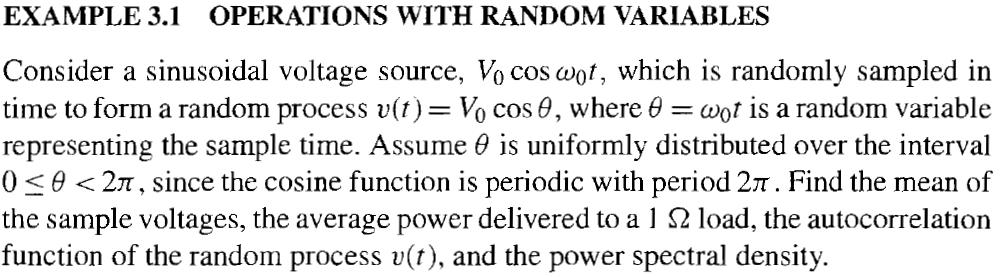
21 Ex
22 3.3 NOISE IN LINEAR SYSTEMS In a wireless radio receiver, both desired signals and undesired noise pass through various stages, such as RF amplifiers, filters, and mixers. These functions generally alter the statistical properties of the noise, and so it is useful to study these effects by considering the general case of transmission of noise through a linear system. Autocorrelation and Power Spectral Density in Linear Systems 22
23 3.3 Noise in Linear Systems Autocorrelation and Power Spectral Density in Linear Systems This result shows that the autocorrelation of the output is given by the double convolution of the autocorrelation of the input with the impulse response: 23
24 Autocorrelation and Power Spectral Density in Linear Systems the equivalent result in terms of power spectral density 24
25 3.3 Noise in Linear Systems Gaussian White Noise through an Ideal Low-pass Filter Filter notation The output noise power is proportional to the filter bandwidth. 25
26 3.3 Noise in Linear Systems Gaussian White Noise through an Integrator 26
27 3.3 Noise in Linear Systems Mixing of Noise LO signal with random phase: This result shows that mixing reduces the average noise power by half. In this case, the factor of one-half is due to the ensemble averaging of the cos 2 w 0 t term over the range of random phase. 27
28 3.3 Noise in Linear Systems Mixing of Noise LO signal with deterministic phase: The variance of the output signal is now a function of time, and represents the instantaneous power of the output signal. To find the time-average output power, we must take the time average of the variance We see that the same average output power is obtained whether the averaging is over the ensemble phase variation, or over time. 28
29 29
30 3.3 Noise in Linear Systems Narrowband Representation of Noise Gaussian white noise passing through a bandpass filter with a center frequency w 0 and bandwidth Δw. x(t) and y(t) are random processes, but are slowly varying due to the narrow bandwidth of the filter. How to prove the valid of this form? 30
31 3.3 Noise in Linear Systems Narrowband Representation of Noise After low-pass filtering with a low-pass cutoff frequency of y(t) terms will remain in the above results., only the x(t) and 31
32 We now find the statistics of x(t) and y(t), and show that these Gaussian random processes have zero mean, the same variance as n(t), and are uncorrelated. 32
33 3.3 Noise in Linear Systems Narrowband Representation of Noise Comparing (3.48) to (3.47) shows that Meaning? 33
34 3.3 Noise in Linear Systems Narrowband Representation of Noise Ans: 34
35 3.4 Basic Threshold Detection 35
36 Probability of error When a binary "1" is transmitted, a detection error will occur if the received signal and noise is less than the threshold level at the sampling time. For a threshold of v o /2, the probability of this event is set Gaussian probability density function Lower limit Define: complementary error function: Meaning? 36
37 37
38 Ex
39 39
40 3.5 Noise temperature and noise figure Equivalent noise temperature Besides being received from the external environment by the antenna, noise is also generated by passive and active components of a wireless receiver system. If an arbitrary noise source is white, so that its power spectral density is not a function of frequency (at least over the frequency range of interest), it can be modeled as an equivalent thermal noise source, and characterized by an equivalent noise temperature. This noise source can be replaced with a noisy resistor of value R, at temperature Te, where Te is an equivalent temperature selected so that the same noise power is delivered to the load. 40
41 Gaussian noise through integrator Consider a noisy amplifier having bandwidth B and power gain G. Let the amplifier be matched to noiseless source and load resistors, as shown in Figure 3.16a. Note the important point that the equivalent noise source is applied at the input to the device, and that the input noise power, Ni = kt e B, must be multiplied by the gain of the amplifier to obtain the output noise power. 41
42 3.5 Noise temperature and noise figure Noise temperature measurement A ratio technique, called the Y-factor method, is often used in practice. To obtain accurate results with this method, the two source temperatures should not be too close together, so that Y is not close to unity. In practice, one noise source may be a resistor at room temperature, while the other is either hotter or colder, depending on whether Te is greater or lesser than To. An active noise source can be used as a "hot" source, while a "cold" source can be obtained by immersing a load resistor in liquid nitrogen (T = 77 K), or liquid helium (T = 4 K). 42
43 3.5 Noise temperature and noise figure Noise Figure A measure of the degradation in the signal-to-noise ratio between the input and output of the component. When noise and a desired signal are applied to the input of a noiseless network, both noise and signal will be attenuated or amplified by the same factor, so that the SNR will be unchanged. But if the network is noisy, the output noise power will be increased to a greater degree than the output signal power, so that the output SNR will be reduced. By definition, the input noise power must be the noise power from a matched load at To = 290 K, that is, Ni = kt o B. (why this definition?) Noise figure is usually expressed in db, obtained as F(dB) = 10 logf 43
44 3.5 Noise temperature and noise figure Noise Figure the output noise power is the sum of the amplified input noise power and the internally generated noise: These results show that equivalent noise temperature and noise figure are interchangeable ways of characterizing the noise properties of RF and microwave components In practice, mixers and amplifiers are usually specified in terms of noise figure, while antennas and receivers are often specified in terms of noise temperature. 2011/2/21 MW & RF Design / Prof. T. -L. Wu 44
45 3.5 Noise temperature and noise figure Noise Figure By definition, the input noise power must be the noise power from a matched load at To = 290 K, that is, Ni = kt o B. (why this definition?) if we define N addd as the noise power added by the network, then the output noise power can be expressed as Since N added is independent of Ni it cannot be proportional to Ni, and so the noise figure depends on the particular value chosen for the input noise power. For this reason Ni must be defined according to a fixed standard if the noise figure is to be meaningful in a general sense 45
46 3.5 Noise temperature and noise figure Noise Figure of a Lossy Line If the input of the line is terminated with a matched load at temperature T, then the entire system is in thermal equilibrium, and the output of the line will appear as a resistor of value R, at temperature T. Another special case occurs when the line or attenuator is at room temperature. Then T = To, and the noise figure reduces to F = L. For instance, a 6 db attenuator at room temperature has a noise figure of 6 db. At higher temperatures, however, the noise figure will be higher. 46
47 3.5 Noise temperature and noise figure Noise Figure of a Cascaded Components In a typical wireless receiver the input signal travels through a cascade of several different components such as filters, amplifiers, mixers, and transmission lines. Each of these stages will progressively degrade the signal-to-noise ratio, so it is important to quantify this effect to evaluate the overall performance of the receiver. We will see that the most critical stage is usually the first, and that later stages generally have a progressively reduced effect on the overall noise figure. This is an important consideration for the design and layout of receiver circuitry. 2011/2/21 MW & RF Design / Prof. T. -L. Wu 47
48 3.5 Noise temperature and noise figure Noise Figure of a Cascaded Components Extend 48
49 49
50 50
51 51
52 3.7 Dynamic Range and Intermodulation Distortion Minimum and maximum realistic power range set by noise level and non-linear effect Devices such as diodes and transistors are nonlinear components, and it is this nonlinearity that is of great utility for functions such as amplification, detection, and frequency conversion. Nonlinear device characteristics, however, can also lead to undesired responses such as gain compression and the generation of spurious frequency components. These effects may produce increased losses, signal distortion, and possible interference with other radio channels or services. Taylor series of a diode or transistor: 52
53 3.7 Dynamic Range and Intermodulation Distortion If a0 is the only nonzero coefficient, the network functions as a rectifier, converting an AC signal to DC. If a1 is the only nonzero coefficient, we have a linear attenuator (al < 1) or amplifier (al > 1). If a2 is the only nonzero coefficient, we can achieve mixing and other frequency conversion functions. Usually, however, practical devices have a series expansion containing many nonzero terms, and a combination of several of these effects will occur. We consider some important special cases below. 53
54 3.7 Dynamic Range and Intermodulation Distortion Gain Compression A single frequency sinusoid is applied to the input of a general nonlinear network. a3 is usually negative The result shows that the voltage gain is equal to the a 1, coefficient, as expected, but with an additional term proportional to the square of the input voltage amplitude. a3 is typically negative, so that the gain of the amplifier tends to decrease for large values of Vo. This effect is called gain compression, or saturation. Meaning? 54
55 3.7 Dynamic Range and Intermodulation Distortion Gain Compression Physically, this is usually due to the fact that the instantaneous output voltage of an amplifier is limited by the power supply voltage used to bias the active device. To quantify the linear operating range of the amplifier, we define the 1 db compression point as the power level for which the output power has decreased by 1 db from the ideal characteristic. For amplifiers P 1 is usually specified as an output power, while for mixers P l is usually specified in terms of input power. A typical amplifier response 55
56 3.7 Dynamic Range and Intermodulation Distortion Intermodulation distortion Consider a two-tone input voltage, consisting of two closely spaced frequencies, 56
57 3.7 Dynamic Range and Intermodulation Distortion Intermodulation distortion The first four of these will again be located far from wl and w2, and will typically be outside the passband of the component. But the two difference terms produce products located near the original input signals at w1 and w2, and so cannot be easily filtered from the passband of an amplifier. 57
58 Third order intercept point Since power is proportional to the square of voltage, we can also say that the output power of third-order products must increase as the cube of the input power, So for small input powers the third-order intermodulation products must be very small, but will increase quickly as input power increases. Since these two lines have different slopes, they will intersect, typically at a point above the onset of compression. This hypothetical intersection point is called the thirdorder intercept point, denoted P3, and specified as either an input or an output power. Usually P3 is referenced at the output for amplifiers, and at the input for mixers. Many practical components follow the approximate rule that P3 is 12 to 15 db greater than P1 58
59 3.7 Dynamic Range and Intermodulation Distortion Intermodulation distortion By At P 3 59
60 Dynamic range We can define dynamic range in a general sense as the operating range for which a component or system has desirable characteristics. PA:power range that is limited at the low end by noise and at the high end by the compression point. This is essentially the linear operating range for the amplifier, and is called the linear dynamic range (DRe ). LNA or mixer: operation may be limited by noise at the low end and the maximum power level for which intermodulation distortion becomes unacceptable. This is effectively the operating range for which spurious responses are minimal, and is called the spurious-free dynamic range (DRf). 60
61 3.7 Dynamic Range and Intermodulation Distortion Dynamic Range The spurious free dynamic range is defined as the maximum output signal power for which the power of the third-order intermodulation product is equal to the noise level of the component. 61
62 62
63 3.7 Dynamic Range and Intermodulation Distortion Intercept Point of Cascaded Components As in the case of noise figure, the cascade connection of components has the effect of degrading (lowering) the third-order intercept point. Unlike the case of a cascade of noisy components, however, the intermodulation products in a cascaded system are deterministic (coherent), so we cannot simply add powers, but must deal with voltages. 63
64 3.7 Dynamic Range and Intermodulation Distortion Intercept Point of Cascaded Components 64

65 Mar. 7, 2008
66 Passive intermodulation Usually occurs at base station of cellular phone due to its high output power and large number of channels. 66
67 HW: 3.7, 3.9, 3.15, 3.16, 3.18, 3.19, 3.21, 3.25, 3.26,
Part A: Question & Answers UNIT I AMPLITUDE MODULATION
 PANDIAN SARASWATHI YADAV ENGINEERING COLLEGE DEPARTMENT OF ELECTRONICS & COMMUNICATON ENGG. Branch: ECE EC6402 COMMUNICATION THEORY Semester: IV Part A: Question & Answers UNIT I AMPLITUDE MODULATION 1.
RF Fundamental Concepts and Performance Parameters
 RF Fundamental Concepts and erformance arameters CCE 50 RF and Microwave System Design Dr. Owen Casha B. Eng. (Hons.) h.d. 09/0/0 Overview Introduction Nonlinearity and Time Variance System Noise Thermal
Outline. Noise and Distortion. Noise basics Component and system noise Distortion INF4420. Jørgen Andreas Michaelsen Spring / 45 2 / 45
 INF440 Noise and Distortion Jørgen Andreas Michaelsen Spring 013 1 / 45 Outline Noise basics Component and system noise Distortion Spring 013 Noise and distortion / 45 Introduction We have already considered
Receiver Design. Prof. Tzong-Lin Wu EMC Laboratory Department of Electrical Engineering National Taiwan University 2011/2/21
 Receiver Design Prof. Tzong-Lin Wu EMC Laboratory Department of Electrical Engineering National Taiwan University 2011/2/21 MW & RF Design / Prof. T. -L. Wu 1 The receiver mush be very sensitive to -110dBm
1. Distortion in Nonlinear Systems
 ECE145A/ECE18A Performance Limitations of Amplifiers 1. Distortion in Nonlinear Systems The upper limit of useful operation is limited by distortion. All analog systems and components of systems (amplifiers
6.976 High Speed Communication Circuits and Systems Lecture 20 Performance Measures of Wireless Communication
 6.976 High Speed Communication Circuits and Systems Lecture 20 Performance Measures of Wireless Communication Michael Perrott Massachusetts Institute of Technology Copyright 2003 by Michael H. Perrott
Module 10 : Receiver Noise and Bit Error Ratio
 Module 10 : Receiver Noise and Bit Error Ratio Lecture : Receiver Noise and Bit Error Ratio Objectives In this lecture you will learn the following Receiver Noise and Bit Error Ratio Shot Noise Thermal
+ 2. Basic concepts of RFIC design
 + 2. Basic concepts of RFIC design 1 A. Thanachayanont RF Microelectronics + General considerations: 2 Units in RF design n Voltage gain and power gain n Ap and Av are equal if vin and vout appear across
NOISE INTERNAL NOISE. Thermal Noise
 NOISE INTERNAL NOISE......1 Thermal Noise......1 Shot Noise......2 Frequency dependent noise......3 THERMAL NOISE......3 Resistors in series......3 Resistors in parallel......4 Power Spectral Density......4
Chapter 2: Signal Representation
 Chapter 2: Signal Representation Aveek Dutta Assistant Professor Department of Electrical and Computer Engineering University at Albany Spring 2018 Images and equations adopted from: Digital Communications
6.976 High Speed Communication Circuits and Systems Lecture 8 Noise Figure, Impact of Amplifier Nonlinearities
 6.976 High Speed Communication Circuits and Systems Lecture 8 Noise Figure, Impact of Amplifier Nonlinearities Michael Perrott Massachusetts Institute of Technology Copyright 2003 by Michael H. Perrott
Gábor C. Temes. School of Electrical Engineering and Computer Science Oregon State University. 1/25
 Gábor C. Temes School of Electrical Engineering and Computer Science Oregon State University temes@ece.orst.edu 1/25 Noise Intrinsic (inherent) noise: generated by random physical effects in the devices.
Notes on Optical Amplifiers
 Notes on Optical Amplifiers Optical amplifiers typically use energy transitions such as those in atomic media or electron/hole recombination in semiconductors. In optical amplifiers that use semiconductor
Analog Communication (10EC53)
") Introduction The function of the communication system is to make available at the destination a signal originating at a distant point. This signal is called the desired signal. Unfortunately, during the
Introduction The function of the communication system is to make available at the destination a signal originating at a distant point. This signal is called the desired signal. Unfortunately, during the
Problem Sheet 1 Probability, random processes, and noise
 Problem Sheet 1 Probability, random processes, and noise 1. If F X (x) is the distribution function of a random variable X and x 1 x 2, show that F X (x 1 ) F X (x 2 ). 2. Use the definition of the cumulative
EC2252: COMMUNICATION THEORY SEM / YEAR: II year DEPARTMENT OF ELECTRONICS AND COMMUNICATION ENGINEERING
 EC2252: COMMUNICATION THEORY SEM / YEAR: II year DEPARTMENT OF ELECTRONICS AND COMMUNICATION ENGINEERING QUESTION BANK SUBJECT CODE : EC2252 SEM / YEAR : II year SUBJECT NAME : COMMUNICATION THEORY UNIT
Microwave Seminar. Noise and Bit Error Ratio. J. Richie. Spring 2013
 Microwave Seminar Noise and Bit Error Ratio J. Richie Spring 2013 Outline Noise Noise and Equivalent Temperature Noise Figure Small Scale Fade and Multipath Impulse Response Model Types of Fading Modulation
Mobile Radio Propagation Channel Models
 Wireless Information Transmission System Lab. Mobile Radio Propagation Channel Models Institute of Communications Engineering National Sun Yat-sen University Table of Contents Introduction Propagation
AVN Training HartRAO 2016
 AVN Training HartRAO 2016 Microwave 1 Overview Introduction to basic components used in microwave receivers. Performance characteristics of these components. Assembly of components into a complete microwave
EENG473 Mobile Communications Module 3 : Week # (12) Mobile Radio Propagation: Small-Scale Path Loss
 Mobile Radio Propagation: Small-Scale Path Loss") EENG473 Mobile Communications Module 3 : Week # (12) Mobile Radio Propagation: Small-Scale Path Loss Introduction Small-scale fading is used to describe the rapid fluctuation of the amplitude of a radio
EENG473 Mobile Communications Module 3 : Week # (12) Mobile Radio Propagation: Small-Scale Path Loss Introduction Small-scale fading is used to describe the rapid fluctuation of the amplitude of a radio
System Noise Power 1
 System Noise Power 1 System Noise Power 1 Performance of system is determined by C/N ratio. Most systems require C/N > 10 db. (Remember, in dbs: C N > 10 db) Hence usually: C > N + 10 db We need to know
Chapter 1: Introduction. EET-223: RF Communication Circuits Walter Lara
 Chapter 1: Introduction EET-223: RF Communication Circuits Walter Lara Introduction Electronic communication involves transmission over medium from source to destination Information can contain voice,
Radio Receiver Architectures and Analysis
 Radio Receiver Architectures and Analysis Robert Wilson December 6, 01 Abstract This article discusses some common receiver architectures and analyzes some of the impairments that apply to each. 1 Contents
RF/IF Terminology and Specs
 RF/IF Terminology and Specs Contributors: Brad Brannon John Greichen Leo McHugh Eamon Nash Eberhard Brunner 1 Terminology LNA - Low-Noise Amplifier. A specialized amplifier to boost the very small received
WIRELESS COMMUNICATION TECHNOLOGIES (16:332:546) LECTURE 5 SMALL SCALE FADING
 LECTURE 5 SMALL SCALE FADING") WIRELESS COMMUNICATION TECHNOLOGIES (16:332:546) LECTURE 5 SMALL SCALE FADING Instructor: Dr. Narayan Mandayam Slides: SabarishVivek Sarathy A QUICK RECAP Why is there poor signal reception in urban clutters?
WIRELESS COMMUNICATION TECHNOLOGIES (16:332:546) LECTURE 5 SMALL SCALE FADING Instructor: Dr. Narayan Mandayam Slides: SabarishVivek Sarathy A QUICK RECAP Why is there poor signal reception in urban clutters?
High Dynamic Range Receiver Parameters
 High Dynamic Range Receiver Parameters The concept of a high-dynamic-range receiver implies more than an ability to detect, with low distortion, desired signals differing, in amplitude by as much as 90
RF, Microwave & Wireless. All rights reserved
 RF, Microwave & Wireless All rights reserved 1 Non-Linearity Phenomenon All rights reserved 2 Physical causes of nonlinearity Operation under finite power-supply voltages Essential non-linear characteristics
Michael F. Toner, et. al.. "Distortion Measurement." Copyright 2000 CRC Press LLC. <
 Michael F. Toner, et. al.. "Distortion Measurement." Copyright CRC Press LLC. . Distortion Measurement Michael F. Toner Nortel Networks Gordon W. Roberts McGill University 53.1
ECEN474: (Analog) VLSI Circuit Design Fall 2011
 VLSI Circuit Design Fall 2011") ECEN474: (Analog) LSI Circuit Design Fall 011 Lecture 1: Noise Sebastian Hoyos Analog & Mixed-Signal Center Texas A&M Uniersity Announcements Reading Razais CMOS Book Chapter 7 Agenda Noise Types Noise
ECEN474: (Analog) LSI Circuit Design Fall 011 Lecture 1: Noise Sebastian Hoyos Analog & Mixed-Signal Center Texas A&M Uniersity Announcements Reading Razais CMOS Book Chapter 7 Agenda Noise Types Noise
8.2 Common Forms of Noise
 8.2 Common Forms of Noise Johnson or thermal noise shot or Poisson noise 1/f noise or drift interference noise impulse noise real noise 8.2 : 1/19 Johnson Noise Johnson noise characteristics produced by
CHAPTER 3 Noise in Amplitude Modulation Systems
 CHAPTER 3 Noise in Amplitude Modulation Systems NOISE Review: Types of Noise External (Atmospheric(sky),Solar(Cosmic),Hotspot) Internal(Shot, Thermal) Parameters of Noise o Signal to Noise ratio o Noise
ANALOGUE TRANSMISSION OVER FADING CHANNELS
 J.P. Linnartz EECS 290i handouts Spring 1993 ANALOGUE TRANSMISSION OVER FADING CHANNELS Amplitude modulation Various methods exist to transmit a baseband message m(t) using an RF carrier signal c(t) =
ECE 476/ECE 501C/CS Wireless Communication Systems Winter Lecture 6: Fading
 ECE 476/ECE 501C/CS 513 - Wireless Communication Systems Winter 2004 Lecture 6: Fading Last lecture: Large scale propagation properties of wireless systems - slowly varying properties that depend primarily
ECE 476/ECE 501C/CS Wireless Communication Systems Winter Lecture 6: Fading
 ECE 476/ECE 501C/CS 513 - Wireless Communication Systems Winter 2005 Lecture 6: Fading Last lecture: Large scale propagation properties of wireless systems - slowly varying properties that depend primarily
Channel Characteristics and Impairments
 ELEX 3525 : Data Communications 2013 Winter Session Channel Characteristics and Impairments is lecture describes some of the most common channel characteristics and impairments. A er this lecture you should
Wideband Channel Characterization. Spring 2017 ELE 492 FUNDAMENTALS OF WIRELESS COMMUNICATIONS 1
 Wideband Channel Characterization Spring 2017 ELE 492 FUNDAMENTALS OF WIRELESS COMMUNICATIONS 1 Wideband Systems - ISI Previous chapter considered CW (carrier-only) or narrow-band signals which do NOT
ECE 476/ECE 501C/CS Wireless Communication Systems Winter Lecture 6: Fading
 ECE 476/ECE 501C/CS 513 - Wireless Communication Systems Winter 2003 Lecture 6: Fading Last lecture: Large scale propagation properties of wireless systems - slowly varying properties that depend primarily
TSEK02: Radio Electronics Lecture 8: RX Nonlinearity Issues, Demodulation. Ted Johansson, EKS, ISY
 TSEK02: Radio Electronics Lecture 8: RX Nonlinearity Issues, Demodulation Ted Johansson, EKS, ISY RX Nonlinearity Issues: 2.2, 2.4 Demodulation: not in the book 2 RX nonlinearities System Nonlinearity
Local Oscillator Phase Noise and its effect on Receiver Performance C. John Grebenkemper
 Watkins-Johnson Company Tech-notes Copyright 1981 Watkins-Johnson Company Vol. 8 No. 6 November/December 1981 Local Oscillator Phase Noise and its effect on Receiver Performance C. John Grebenkemper All
ELEN 701 RF & Microwave Systems Engineering. Lecture 8 November 8, 2006 Dr. Michael Thorburn Santa Clara University
 ELEN 701 RF & Microwave Systems Engineering Lecture 8 November 8, 2006 Dr. Michael Thorburn Santa Clara University System Noise Figure Signal S1 Noise N1 GAIN = G Signal G x S1 Noise G x (N1+No) Self Noise
RADIO RECEIVERS ECE 3103 WIRELESS COMMUNICATION SYSTEMS
 RADIO RECEIVERS ECE 3103 WIRELESS COMMUNICATION SYSTEMS FUNCTIONS OF A RADIO RECEIVER The main functions of a radio receiver are: 1. To intercept the RF signal by using the receiver antenna 2. Select the
APPLICATION NOTE 3942 Optimize the Buffer Amplifier/ADC Connection
 Maxim > Design Support > Technical Documents > Application Notes > Communications Circuits > APP 3942 Maxim > Design Support > Technical Documents > Application Notes > High-Speed Interconnect > APP 3942
Today s menu. Last lecture. Series mode interference. Noise and interferences R/2 V SM Z L. E Th R/2. Voltage transmission system
 Last lecture Introduction to statistics s? Random? Deterministic? Probability density functions and probabilities? Properties of random signals. Today s menu Effects of noise and interferences in measurement
Agilent Fundamentals of RF and Microwave Noise Figure Measurements
 Agilent Fundamentals of RF and Microwave Noise Figure Measurements Application Note 57-1 2 Table of Contents 1. What is Noise Figure?.....................................4 Introduction.................................................4
Satellite Communications: Part 4 Signal Distortions & Errors and their Relation to Communication Channel Specifications. Howard Hausman April 1, 2010
 Satellite Communications: Part 4 Signal Distortions & Errors and their Relation to Communication Channel Specifications Howard Hausman April 1, 2010 Satellite Communications: Part 4 Signal Distortions
Understanding Noise Figure
 Understanding Noise Figure Iulian Rosu, YO3DAC / VA3IUL, http://www.qsl.net/va3iul One of the most frequently discussed forms of noise is known as Thermal Noise. Thermal noise is a random fluctuation in
Mobile Radio Propagation: Small-Scale Fading and Multi-path
 Mobile Radio Propagation: Small-Scale Fading and Multi-path 1 EE/TE 4365, UT Dallas 2 Small-scale Fading Small-scale fading, or simply fading describes the rapid fluctuation of the amplitude of a radio
two computers. 2- Providing a channel between them for transmitting and receiving the signals through it.
 1. Introduction: Communication is the process of transmitting the messages that carrying information, where the two computers can be communicated with each other if the two conditions are available: 1-
TSEK02: Radio Electronics Lecture 8: RX Nonlinearity Issues, Demodulation. Ted Johansson, EKS, ISY
 TSEK02: Radio Electronics Lecture 8: RX Nonlinearity Issues, Demodulation Ted Johansson, EKS, ISY 2 RX Nonlinearity Issues, Demodulation RX nonlinearities (parts of 2.2) System Nonlinearity Sensitivity
Narrow- and wideband channels
 RADIO SYSTEMS ETIN15 Lecture no: 3 Narrow- and wideband channels Ove Edfors, Department of Electrical and Information technology Ove.Edfors@eit.lth.se 27 March 2017 1 Contents Short review NARROW-BAND
Nonlinear Companding Transform Algorithm for Suppression of PAPR in OFDM Systems
 Nonlinear Companding Transform Algorithm for Suppression of PAPR in OFDM Systems P. Guru Vamsikrishna Reddy 1, Dr. C. Subhas 2 1 Student, Department of ECE, Sree Vidyanikethan Engineering College, Andhra
Theory of Telecommunications Networks
 Theory of Telecommunications Networks Anton Čižmár Ján Papaj Department of electronics and multimedia telecommunications CONTENTS Preface... 5 1 Introduction... 6 1.1 Mathematical models for communication
Wireless Communication: Concepts, Techniques, and Models. Hongwei Zhang
 Wireless Communication: Concepts, Techniques, and Models Hongwei Zhang http://www.cs.wayne.edu/~hzhang Outline Digital communication over radio channels Channel capacity MIMO: diversity and parallel channels
Lecture 6. Angle Modulation and Demodulation
 Lecture 6 and Demodulation Agenda Introduction to and Demodulation Frequency and Phase Modulation Angle Demodulation FM Applications Introduction The other two parameters (frequency and phase) of the carrier
WIRELESS TRANSCEIVER ARCHITECTURE
 WIRELESS TRANSCEIVER ARCHITECTURE BRIDGING RF AND DIGITAL COMMUNICATIONS Pierre Baudin Wiley Contents Preface List of Abbreviations Nomenclature xiii xvii xxi Part I BETWEEN MAXWELL AND SHANNON 1 The Digital
Understanding Mixers Terms Defined, and Measuring Performance
 Understanding Mixers Terms Defined, and Measuring Performance Mixer Terms Defined Statistical Processing Applied to Mixers Today's stringent demands for precise electronic systems place a heavy burden
Understanding IP2 and IP3 Issues in Direct Conversion Receivers for WCDMA Wide Area Basestations
 L DESIGN FEATURES Understanding I and I3 Issues in Direct Conversion Receivers for Wide Area Basestations Introduction A direct conversion receiver architecture offers several advantages over the traditional
RECEIVER SENSITIVITY / NOISE
 RECEIVER SENSITIVITY / NOISE RECEIVER SENSITIVITY Sensitivity in a receiver is normally taken as the imum input signal (S ) required to produce a specified output signal having a specified signal-to-noise
ELEC3106 Electronics. Lecture notes: non-linearity and noise. Objective. Non-linearity. Non-linearity measures
 ELEC316 Electronics Lecture notes: non-linearity and noise Objective The objective o these brie notes is to supplement the textbooks used in the course on the topic o non-linearity and electrical noise.
The Friis Transmission Formula
 The Friis Transmission Formula If we assume that the antennas are aligned for maximum transmission and reception, then in free space, P RX = G TXA e P TX 4πr 2 where A e is the receiving aperture of the
Termination Insensitive Mixers By Howard Hausman President/CEO, MITEQ, Inc. 100 Davids Drive Hauppauge, NY
 Termination Insensitive Mixers By Howard Hausman President/CEO, MITEQ, Inc. 100 Davids Drive Hauppauge, NY 11788 hhausman@miteq.com Abstract Microwave mixers are non-linear devices that are used to translate
CHAPTER 3 CMOS LOW NOISE AMPLIFIERS
 46 CHAPTER 3 CMOS LOW NOISE AMPLIFIERS 3.1 INTRODUCTION The Low Noise Amplifier (LNA) plays an important role in the receiver design. LNA serves as the first block in the RF receiver. It is a critical
TSEK02: Radio Electronics Lecture 6: Propagation and Noise. Ted Johansson, EKS, ISY
 TSEK02: Radio Electronics Lecture 6: Propagation and Noise Ted Johansson, EKS, ISY 2 Propagation and Noise - Channel and antenna: not in the Razavi book - Noise: 2.3 The wireless channel The antenna Signal
MSK has three important properties. However, the PSD of the MSK only drops by 10log 10 9 = 9.54 db below its midband value at ft b = 0.
 Gaussian MSK MSK has three important properties Constant envelope (why?) Relatively narrow bandwidth Coherent detection performance equivalent to that of QPSK However, the PSD of the MSK only drops by
Introduction to Receivers
 Introduction to Receivers Purpose: translate RF signals to baseband Shift frequency Amplify Filter Demodulate Why is this a challenge? Interference Large dynamic range required Many receivers must be capable
Noise Lecture 1. EEL6935 Chris Dougherty (TA)
") Noise Lecture 1 EEL6935 Chris Dougherty (TA) An IEEE Definition of Noise The IEEE Standard Dictionary of Electrical and Electronics Terms defines noise (as a general term) as: unwanted disturbances superposed
Noise Lecture 1 EEL6935 Chris Dougherty (TA) An IEEE Definition of Noise The IEEE Standard Dictionary of Electrical and Electronics Terms defines noise (as a general term) as: unwanted disturbances superposed
15.Calculate the local oscillator frequency if incoming frequency is F1 and translated carrier frequency
 DEPARTMENT OF ELECTRONICS & COMMUNICATION ENGINEERING SUBJECT NAME:COMMUNICATION THEORY YEAR/SEM: II/IV SUBJECT CODE: EC 6402 UNIT I:l (AMPLITUDE MODULATION) PART A 1. Compute the bandwidth of the AMP
Thermal Johnson Noise Generated by a Resistor
 Thermal Johnson Noise Generated by a Resistor Complete Pre- Lab before starting this experiment HISTORY In 196, experimental physicist John Johnson working in the physics division at Bell Labs was researching
Introduction to Analog And Digital Communications
 Introduction to Analog And Digital Communications Second Edition Simon Haykin, Michael Moher Chapter 11 System and Noise Calculations 11.1 Electrical Noise 11.2 Noise Figure 11.3 Equivalent Noise Temperature
PRINCIPLES OF COMMUNICATIONS
 PRINCIPLES OF COMMUNICATIONS Systems, Modulation, and Noise SIXTH EDITION INTERNATIONAL STUDENT VERSION RODGER E. ZIEMER University of Colorado at Colorado Springs WILLIAM H. TRANTER Virginia Polytechnic
FIBER OPTICS. Prof. R.K. Shevgaonkar. Department of Electrical Engineering. Indian Institute of Technology, Bombay. Lecture: 20
 FIBER OPTICS Prof. R.K. Shevgaonkar Department of Electrical Engineering Indian Institute of Technology, Bombay Lecture: 20 Photo-Detectors and Detector Noise Fiber Optics, Prof. R.K. Shevgaonkar, Dept.
9.4 Temporal Channel Models
 ECEn 665: Antennas and Propagation for Wireless Communications 127 9.4 Temporal Channel Models The Rayleigh and Ricean fading models provide a statistical model for the variation of the power received
THE BASICS OF RADIO SYSTEM DESIGN
 THE BASICS OF RADIO SYSTEM DESIGN Mark Hunter * Abstract This paper is intended to give an overview of the design of radio transceivers to the engineer new to the field. It is shown how the requirements
Low noise amplifier, principles
 1 Low noise amplifier, principles l l Low noise amplifier (LNA) design Introduction -port noise theory, review LNA gain/noise desense Bias network and its effect on LNA IP3 LNA stability References Why
DIGITAL COMMUNICATION
 DEPARTMENT OF ELECTRICAL &ELECTRONICS ENGINEERING DIGITAL COMMUNICATION Spring 00 Yrd. Doç. Dr. Burak Kelleci OUTLINE Quantization Pulse-Code Modulation THE QUANTIZATION PROCESS A continuous signal has
E3 237 Integrated Circuits for Wireless Communication
 E3 237 Integrated Circuits for Wireless Communication Lecture 8: Noise in Components Gaurab Banerjee Department of Electrical Communication Engineering, Indian Institute of Science, Bangalore banerjee@ece.iisc.ernet.in
Wireless Channel Propagation Model Small-scale Fading
 Wireless Channel Propagation Model Small-scale Fading Basic Questions T x What will happen if the transmitter - changes transmit power? - changes frequency? - operates at higher speed? Transmit power,
Figure 1 shows the placement of a mixer in a ANTENNA. f R f I LNA R I. Figure 1. Schematic diagram showing mixer placement in a receiver front end.
 Mixers: Part 1 Characteristics and Performance The mixer is a critical component in modern RF systems. Since it is usually the first or second device from the RF input, the performance of the mixer is
Lecture 3: Data Transmission
 Lecture 3: Data Transmission 1 st semester 1439-2017 1 By: Elham Sunbu OUTLINE Data Transmission DATA RATE LIMITS Transmission Impairments Examples DATA TRANSMISSION The successful transmission of data
Digital Signal Analysis
 Digital Signal Analysis Objectives - Provide a digital modulation overview - Review common digital radio impairments Digital Modulation Overview Signal Characteristics to Modify Polar Display / IQ Relationship
Project = An Adventure : Wireless Networks. Lecture 4: More Physical Layer. What is an Antenna? Outline. Page 1
 Project = An Adventure 18-759: Wireless Networks Checkpoint 2 Checkpoint 1 Lecture 4: More Physical Layer You are here Done! Peter Steenkiste Departments of Computer Science and Electrical and Computer
Signals, Sound, and Sensation
 Signals, Sound, and Sensation William M. Hartmann Department of Physics and Astronomy Michigan State University East Lansing, Michigan Л1Р Contents Preface xv Chapter 1: Pure Tones 1 Mathematics of the
Lab course Analog Part of a State-of-the-Art Mobile Radio Receiver
 Communication Technology Laboratory Wireless Communications Group Prof. Dr. A. Wittneben ETH Zurich, ETF, Sternwartstrasse 7, 8092 Zurich Tel 41 44 632 36 11 Fax 41 44 632 12 09 Lab course Analog Part
Narrow- and wideband channels
 RADIO SYSTEMS ETIN15 Lecture no: 3 Narrow- and wideband channels Ove Edfors, Department of Electrical and Information technology Ove.Edfors@eit.lth.se 2012-03-19 Ove Edfors - ETIN15 1 Contents Short review
Downloaded from 1
 VII SEMESTER FINAL EXAMINATION-2004 Attempt ALL questions. Q. [1] How does Digital communication System differ from Analog systems? Draw functional block diagram of DCS and explain the significance of
Appendix. Harmonic Balance Simulator. Page 1
 Appendix Harmonic Balance Simulator Page 1 Harmonic Balance for Large Signal AC and S-parameter Simulation Harmonic Balance is a frequency domain analysis technique for simulating distortion in nonlinear
Digital Communication System
 Digital Communication System Purpose: communicate information at required rate between geographically separated locations reliably (quality) Important point: rate, quality spectral bandwidth, power requirements
VALLIAMMAI ENGINEERING COLLEGE
 VALLIAMMAI ENGINEERING COLLEGE SRM Nagar, Kattankulathur 603 203. DEPARTMENT OF ELECTRONICS & COMMUNICATION ENGINEERING QUESTION BANK SUBJECT : EC6402 COMMUNICATION THEORY SEM / YEAR: IV / II year B.E.
CALIFORNIA STATE UNIVERSITY, NORTHRIDGE FADING CHANNEL CHARACTERIZATION AND MODELING
 CALIFORNIA STATE UNIVERSITY, NORTHRIDGE FADING CHANNEL CHARACTERIZATION AND MODELING A graduate project submitted in partial fulfillment of the requirements For the degree of Master of Science in Electrical
Chapter 3 Digital Transmission Fundamentals
 Chapter 3 Digital Transmission Fundamentals Characterization of Communication Channels Fundamental Limits in Digital Transmission CSE 323, Winter 200 Instructor: Foroohar Foroozan Chapter 3 Digital Transmission
Contents. Introduction 1 1 Suggested Reading 2 2 Equipment and Software Tools 2 3 Experiment 2
 ECE363, Experiment 02, 2018 Communications Lab, University of Toronto Experiment 02: Noise Bruno Korst - bkf@comm.utoronto.ca Abstract This experiment will introduce you to some of the characteristics
NOISE FACTOR [or noise figure (NF) in decibels] is an
![NOISE FACTOR [or noise figure (NF) in decibels] is an](/thumbs/75/72198424.jpg "NOISE FACTOR [or noise figure (NF) in decibels] is an") 1330 IEEE TRANSACTIONS ON CIRCUITS AND SYSTEMS I: REGULAR PAPERS, VOL. 51, NO. 7, JULY 2004 Noise Figure of Digital Communication Receivers Revisited Won Namgoong, Member, IEEE, and Jongrit Lerdworatawee,
1330 IEEE TRANSACTIONS ON CIRCUITS AND SYSTEMS I: REGULAR PAPERS, VOL. 51, NO. 7, JULY 2004 Noise Figure of Digital Communication Receivers Revisited Won Namgoong, Member, IEEE, and Jongrit Lerdworatawee,
Time division multiplexing The block diagram for TDM is illustrated as shown in the figure
 CHAPTER 2 Syllabus: 1) Pulse amplitude modulation 2) TDM 3) Wave form coding techniques 4) PCM 5) Quantization noise and SNR 6) Robust quantization Pulse amplitude modulation In pulse amplitude modulation,
2.1 BASIC CONCEPTS Basic Operations on Signals Time Shifting. Figure 2.2 Time shifting of a signal. Time Reversal.
 1 2.1 BASIC CONCEPTS 2.1.1 Basic Operations on Signals Time Shifting. Figure 2.2 Time shifting of a signal. Time Reversal. 2 Time Scaling. Figure 2.4 Time scaling of a signal. 2.1.2 Classification of Signals
ELT Receiver Architectures and Signal Processing Fall Mandatory homework exercises
 ELT-44006 Receiver Architectures and Signal Processing Fall 2014 1 Mandatory homework exercises - Individual solutions to be returned to Markku Renfors by email or in paper format. - Solutions are expected
HY448 Sample Problems
 HY448 Sample Problems 10 November 2014 These sample problems include the material in the lectures and the guided lab exercises. 1 Part 1 1.1 Combining logarithmic quantities A carrier signal with power
PHY 122 Shot Noise. Complete Shot Noise Pre- Lab before starting this experiment
 PHY 122 Shot Noise HISTORY Complete Shot Noise Pre- Lab before starting this experiment In 1918, experimental physicist Walter Scottky working in the research lab at Siemens was investigating the origins
Berkeley. Mixers: An Overview. Prof. Ali M. Niknejad. U.C. Berkeley Copyright c 2014 by Ali M. Niknejad
 Berkeley Mixers: An Overview Prof. Ali M. U.C. Berkeley Copyright c 2014 by Ali M. Mixers Information PSD Mixer f c The Mixer is a critical component in communication circuits. It translates information
TSEK02: Radio Electronics Lecture 6: Propagation and Noise. Ted Johansson, EKS, ISY
 TSEK02: Radio Electronics Lecture 6: Propagation and Noise Ted Johansson, EKS, ISY 2 Propagation and Noise - Channel and antenna: not in the Razavi book - Noise: 2.3 The wireless channel The antenna Signal
Receiver Design for Passive Millimeter Wave (PMMW) Imaging
 Imaging") Introduction Receiver Design for Passive Millimeter Wave (PMMW) Imaging Millimeter Wave Systems, LLC Passive Millimeter Wave (PMMW) sensors are used for remote sensing and security applications. They rely
Introduction Receiver Design for Passive Millimeter Wave (PMMW) Imaging Millimeter Wave Systems, LLC Passive Millimeter Wave (PMMW) sensors are used for remote sensing and security applications. They rely