ECE1750, Spring Week 5 MOSFET Gate Drivers
|
|
|
- Charlotte Franklin
- 5 years ago
- Views:
Transcription
1 ECE1750, Spring 2018 Week 5 MOSFET Gate Drivers 1
2 Power MOSFETs (a high-speed, voltage-controlled switch) D: Drain D If desired, a series blocking diode can be inserted here to prevent reverse current G: Gate G S: Source Switch closes when V GS 4Vdc S N channel MOSFET equivalent circuit Controllability? - Controlled turn on, controlled turn off (but there is an internal antiparallel diode). Thanks to the diode it can conduct in both directions but it cannot block D-S voltages in which VD<VS. Controlled through the gate by voltage. If VGS>VGS,th it conducts. Otherwise, it does not conduct (in the forward direction). 2
3 We Avoid the Linear (Lossy) Region, Using Only the On and Off States Ideal MOSFET on D Ideal MOSFET off D S when V GS = 20 V S when V GS = 0 V 3
4 Main characteristics Static Characteristic Power MOSFETS Ohmic Region ON State Active Region i id id ON State Higher VGS Lower Cutoff (OFF State) VGS<VGS,th v vds VGS,th VDS vgs 4
5 Power MOSFETS Main characteristics Behavioral models Static model (sw) sw = ON when VGS>VGS,th OFF when VGS<VGS,th Dynamic Model G Cgd Cgs id Capacitances (particularly D Cgs) ) need to be charged or rd(t) discharged to turn the MOSFET ON or OFF, respectively Cds RDS,ON S 5
6 We Want to Switch Quickly to Minimize Switching Losses Turn Off Turn On V DS (t) V DS (t) 0 0 I(t) t off I(t) t on 0 0 p LOSS (t) p LOSS (t) 0 Energy lost per turn off 0 Energy lost per turn on Turn off and turn on times limit the frequency of operation because their sum must be considerably less than period T (i.e., 1/f) 6
7 Consider, for example, the turn off V DS (t) 0 I(t) Turn Off V Energy lost per turn off is proportional to V I t off, so we want to keep turn off (and turn on) times as small as possible. 0 I The more often we switch, the more energy loss areas we experience per second. p LOSS (t) t off 0 Energy lost per turn off Thus, switching losses (average W) are proportional to switching frequency f, V, I, t off, and t on. And, of course, there are conduction losses that are equal to the product of RDSon and I squared 7
8 Switching losses With a resistive load, voltage and current waveforms are approximately like (linear commutation) turn-on losses: V off turn-off losses: I on Voff I pon () t tvoff t on poff () t tion t ton ton t off t off Total switching losses: 1 I V I V P p t dt f p t p t dt f t t f t T 6 6 T T on off on off sw () ( on() off ()) ( on off ) sw 0 0
9 Switching losses With in inductive load and an ideal switch, voltage and current waveforms are approximately like More realistic behavior Approximate behavior turn-on losses: pon () t 0 Total switching losses: turn-off losses: V off I on poff () t Ion t Voff t ( tloff, /2) ( tloff, /2) 1 I V I V P p t dt f t f t T 2 2 T on off on off sw () ( L, off ) sw 0
10 Advantages of Operating Above 20kHz Yes, switching losses in power electronic switches do increase with operating frequency, but going beyond 20kHz has important advantages. Among these are Humans cannot hear the circuits For the same desired smoothing effect, L s and C s can be smaller because, as frequency increases and period T decreases, L s and C s charge and discharge less energy per cycle of operation. Smaller L s and C s permit smaller, lighter circuits. Correspondingly, L and C rms ripple currents decrease, so current ratings can be lower. Thus, smaller, lighter circuits. AC transformers are smaller because, for a given voltage rating, the peak flux density in the core is reduced (which means transformer cores can have smaller cross sectional areas A). d db d B sin( ) max t v( t) N NA NA NAB max cos( t ) dt dt dt Thus, smaller, lighter circuits. N = number of turns, ϕ = magnetic flux, B = magnetic field, A = x-sectional area 10
11 Fast Switching Frequencies Previous slide was just to illustrate how, with increased switching frequency, one can reduce the size of AC transformer cores needed: d db d B sin( ) ( ) max t v t N NA NA NABmax dt dt dt Thus, smaller, lighter circuits. cos( t) N = number of turns, ϕ = magnetic flux, B = magnetic field, A = x-sectional area The drawback, of course, to high frequency switching is increased power loss, since: P Total (loss) = P switching loss x number of switching events (or, the switching frequency) This is the downside of high-frequency switching. Thus, one must work to ensure overall losses are reduced by working to reduce the individual switching transition time. 11
12 MOSFETS are usually controlled with a pulse-width modulation (PWM) strategy. In essence, the PWM process involves comparing a sawtooth (or any other periodic function with linear transitions) with a voltage level. If the voltage level is constant, it will tend to produce a constant (dc) output. Sawtooth or triangle adjustable analog input (duty cycle control) Linear portions of sawtooth allows to directly translate voltage levels into time intervals (on-times) 12V Gate Driver (e.g. TC1427) Comparator (e.g., LM393) 12
13 PWM D = 8/12 = Gate Driver (e.g. TC1427) Comparator (e.g., LM393) 13
 Comparator (e.g., LM393) 14")
14 PWM D = 6/12 = Gate Driver (e.g. TC1427) Comparator (e.g., LM393) 14
 Comparator (e.g., LM393) 15")
15 PWM D = 4/12 = 1/3 Gate Driver (e.g. TC1427) Comparator (e.g., LM393) 15
16 MOSFETS are Very Sensitive to Static Electricity Touching the gate lead before the MOSFET is properly mounted will likely ruin the MOSFET But it may not fail right away. Instead, the failure may be gradual. Your circuit will work, but not correctly. Performance gradually deteriorates. When that happens, you can spend unnecessary hours debugging Key indicators of a failed MOSFET are Failed or burning hot driver chip Burning hot gate driver resistor (discolored, or bubbled up) Board scorches or melts underneath the driver chip or gate driver resistor Avoid these problems by mounting the MOSFET last, by using an antistatic wristband, and by not touching the gate lead 16


17 MOSFET Switch Turn-Off Overshoot.. Simple snubber circuit 200kHz, 0.01µF snubber VDS VGS 200kHz, no snubber VDS 100kHz, 0.01µF 01µF snubber VDS VGS VGS 200kHz, µF snubber VDS 50kHz, 0.01µF snubber VDS VGS VGS 17
18 MOSFET Safe Operating Area (SOA) Pulsed drain current must never be exceed Maximum continuous drain current can be exceeded but only for a brief time Operation naturally limited by R DS,on (Ohm s law) Thermal limit (power limit) can be exceeded but only for a brief time Breakdown voltage must never be exceeded 18

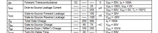
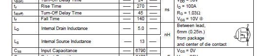
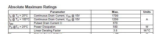
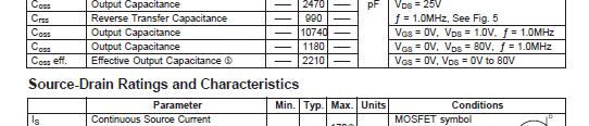
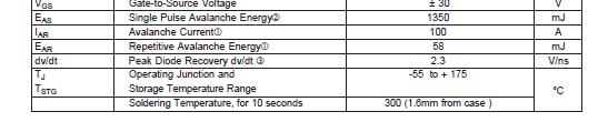
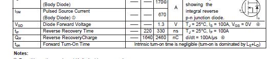
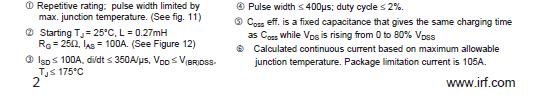
19 MOSFET Datasheet 19
20 Small 10Ω, 100W Resistor. 22Vdc. Vpeak = 240V. MOSFET opens V DS ON V GS OFF DT Note: Ringing is caused by the interaction of parasitic capacitors and inductors. 20
21 Small 10Ω, 100W Resistor. 22Vdc. Vpeak = 40V µF Snubber Cap MOSFET opens 21
22 Small 10Ω, 100W Resistor. 22Vdc. Vpeak = 60V µF Snubber Cap MOSFET opens 22
23 Gate Drivers 23

24 Integrated PWM f 1.2 R T C T MC34060A, Fixed Frequency, PWM, Voltage Mode Single Ended Controller f 1 C R T T 24
Switch closes when V GS 4Vdc. Figure 1. N Channel MOSFET Equivalent Circuit
 Overview MOSFETS are voltage-controlled switches. Unlike triacs, MOSFETS have the capability of being turned on and turned off. They also switch much faster than triacs. As illustrated in Figure 1, the
ECE1750, Spring Week 1 - Components
 ECE1750, Spring 2018 Week 1 - Components 1 Most commonly used power electronic switches: Diodes(aka (a.k.a. rectifiers) Thyristors (a.k.a. silicon controlled rectifiers, SCRs) Power MOSFETs IGBTs 2 But
ECE514 Power Electronics Converter Topologies. Part 2 [100 pts] Design of an RDC snubber for flyback converter
![ECE514 Power Electronics Converter Topologies. Part 2 [100 pts] Design of an RDC snubber for flyback converter](/thumbs/72/67440195.jpg "ECE514 Power Electronics Converter Topologies. Part 2 [100 pts] Design of an RDC snubber for flyback converter") ECE514 Power Electronics Converter Topologies Homework Assignment #4 Due date October 31, 2014, beginning of the lecture Part 1 [100 pts] Redo Term Test 1 (attached) Part 2 [100 pts] Design of an RDC snubber
ECE514 Power Electronics Converter Topologies Homework Assignment #4 Due date October 31, 2014, beginning of the lecture Part 1 [100 pts] Redo Term Test 1 (attached) Part 2 [100 pts] Design of an RDC snubber
Presentation Content Review of Active Clamp and Reset Technique in Single-Ended Forward Converters Design Material/Tools Design procedure and concern
 Active Clamp Forward Converters Design Using UCC2897 Hong Huang August 2007 1 Presentation Content Review of Active Clamp and Reset Technique in Single-Ended Forward Converters Design Material/Tools Design
Data Sheet Explanation
 Data Sheet Explanation V1.2 2014-04 Edition 2014-01 Published by Infineon Technologies AG, 81726 Munich, Germany. 2014 Infineon Technologies AG All Rights Reserved. LEGAL DISCLAIMER THE INFORMATION GIVEN
PFU70R360G / PFD70R360G
 FEATURES New technology for high voltage device Low RDS(on) low conduction losses Small package Ultra low gate charge cause lower driving requirement 100% avalanche tested Halogen Free APPLICATION Power
TO-220 G D S. T C = 25 C unless otherwise noted
 500V N-Channel MOSFET General Description This Power MOSFET is produced using Maple semi s advanced planar stripe DMOS technology. This advanced technology has been especially tailored to minimize on-state
AN-1001 Understanding Power MOSFET Parameters
 AN-1001 Understanding Power MOSFET Parameters www.taiwansemi.com Content 1. Absolute Maximum Ratings... 3 1.1 rain-source Voltage (VS)... 3 1.2 Gate-Source Voltage (VGS)... 3 1.3 Continuous rain Current
Cascode Configuration Eases Challenges of Applying SiC JFETs
 Application Note USCi_AN0004 March 2016 Cascode Configuration Eases Challenges of Applying SiC JFETs John Bendel Abstract The high switching speeds and low R DS(ON) of high-voltage SiC JFETs can significantly
Improvements of LLC Resonant Converter
 Chapter 5 Improvements of LLC Resonant Converter From previous chapter, the characteristic and design of LLC resonant converter were discussed. In this chapter, two improvements for LLC resonant converter
Lab Experiments. Boost converter (Experiment 2) Control circuit (Experiment 1) Power diode. + V g. C Power MOSFET. Load.
 Control circuit (Experiment 1) Power diode. + V g. C Power MOSFET. Load.") Lab Experiments L Power diode V g C Power MOSFET Load Boost converter (Experiment 2) V ref PWM chip UC3525A Gate driver TSC427 Control circuit (Experiment 1) Adjust duty cycle D The UC3525 PWM Control
Lab Experiments L Power diode V g C Power MOSFET Load Boost converter (Experiment 2) V ref PWM chip UC3525A Gate driver TSC427 Control circuit (Experiment 1) Adjust duty cycle D The UC3525 PWM Control
TC = 25 C unless otherwise noted. Maximum lead temperature for soldering purposes, 300 1/8" from case for 5 seconds
 General Description This Power MOSFET is produced Features using Maple semi s Advanced Super-Junction technology. - 7.6A, 500V, R DS(on) typ. = 0.5Ω@ = 10 V This advanced technology has been especially
Conventional Single-Switch Forward Converter Design
 Maxim > Design Support > Technical Documents > Application Notes > Amplifier and Comparator Circuits > APP 3983 Maxim > Design Support > Technical Documents > Application Notes > Power-Supply Circuits
Lecture 4 ECEN 4517/5517
 Lecture 4 ECEN 4517/5517 Experiment 3 weeks 2 and 3: interleaved flyback and feedback loop Battery 12 VDC HVDC: 120-200 VDC DC-DC converter Isolated flyback DC-AC inverter H-bridge v ac AC load 120 Vrms
EPC2201 Power Electronic Devices Tutorial Sheet
 EPC2201 Power Electronic Devices Tutorial heet 1. The ON state forward voltage drop of the controlled static switch in Figure 1 is 2V. Its forward leakage current in the state is 2mA. It is operated with
PFP15T140 / PFB15T140
 FEATURES 1% EAS Test Super high density cell design Extremely Low Intrinsic Capacitances Remarkable Switching Characteristics Extended Safe Operating Area Lower R DS(ON) : 6. mω (Typ.) @ =1V 15V N-Channel
I2-PAK I-PAK. TC = 25 C unless otherwise noted D2-PAK/D-PAK I2-PAK / I-PAK/ TO-220
 General Description This Power MOSFET is produced Features using Maple semi s Advanced Super-Junction technology. - 7.6A, 500V, R DS(on) typ. = 0.5Ω@V GS = 10 V This advanced technology has - been Low
An Improvement in the Virtually Isolated Transformerless Off - Line Power Supply
 An Improvement in the Virtually Isolated Transformerless Off - Line Power Supply Spiros Cofinas Department of Electrotechnics and Computer Science Hellenic Naval Academy Terma Hatzikyriakou, Piraeus GREECE
IRHNJ67130 SURFACE MOUNT (SMD-0.5) REF: MIL-PRF-19500/746. Absolute Maximum Ratings PD-95816D. Features: n Low RDS(on) n Fast Switching
 REF: MIL-PRF-19500/746. Absolute Maximum Ratings PD-95816D. Features: n Low RDS(on) n Fast Switching") PD-9586D RADIATION HARDENED POWER MOSFET SURFACE MOUNT (SMD-.5) IRHNJ673 JANSR2N7587U3 V, N-CHANNEL REF: MIL-PRF-95/746 TECHNOLOGY Product Summary Part Number Radiation Level RDS(on) ID QPL Part Number
PD-9586D RADIATION HARDENED POWER MOSFET SURFACE MOUNT (SMD-.5) IRHNJ673 JANSR2N7587U3 V, N-CHANNEL REF: MIL-PRF-95/746 TECHNOLOGY Product Summary Part Number Radiation Level RDS(on) ID QPL Part Number
SURFACE MOUNT (SMD-1) 100V, P-CHANNEL. Absolute Maximum Ratings. Product Summary
 100V, P-CHANNEL. Absolute Maximum Ratings. Product Summary") PD-9454A HEXFET POWER MOSFET SURFACE MOUNT (SMD-) IRF5N52 V, P-CHANNEL Product Summary Part Number BVDSS RDS(on) ID IRF5N52 -V.6Ω -3A Fifth Generation HEXFET power MOSFETs from International Rectifier
PD-9454A HEXFET POWER MOSFET SURFACE MOUNT (SMD-) IRF5N52 V, P-CHANNEL Product Summary Part Number BVDSS RDS(on) ID IRF5N52 -V.6Ω -3A Fifth Generation HEXFET power MOSFETs from International Rectifier
UNISONIC TECHNOLOGIES CO., LTD
 UNISONIC TECHNOLOGIES CO., LTD 5A, 650V N-CHANNEL POWER MOSFET DESCRIPTION The UTC 5N65 is a high voltage power MOSFET designed to have better characteristics, such as fast switching time, low gate charge,
AIC1896. Efficiency (%) I LED R1. Fig. 1 Li-Ion Powered Driver for three white LEDs
 I LED R1. Fig. 1 Li-Ion Powered Driver for three white LEDs") .MHz SOT2 Current-Mode Step-Up DC/DC Converter FEATURES Fixed Frequency.MHz Current-Mode PWM Operation. Adjustable Output Voltage up to 0V. Guaranteed V/ 200mA Output with 5V Input. 2.5V to 0V Input Range.
.MHz SOT2 Current-Mode Step-Up DC/DC Converter FEATURES Fixed Frequency.MHz Current-Mode PWM Operation. Adjustable Output Voltage up to 0V. Guaranteed V/ 200mA Output with 5V Input. 2.5V to 0V Input Range.
AN2170 APPLICATION NOTE MOSFET Device Effects on Phase Node Ringing in VRM Power Converters INTRODUCTION
 AN2170 APPLICATION NOTE MOSFET Device Effects on Phase Node Ringing in VRM Power Converters INTRODUCTION The growth in production volume of industrial equipment (e.g., power DC-DC converters devoted to
UNISONIC TECHNOLOGIES CO., LTD 5N60
 UNISONIC TECHNOLOGIES CO., LTD 5N60 5A, 600V N-CHANNEL POWER MOSFET DESCRIPTION The UTC 5N60 is a high voltage power MOSFET and is designed to have better characteristics, such as fast switching time,
Analog and Telecommunication Electronics
 Politecnico di Torino - ICT School Analog and Telecommunication Electronics F2 Active power devices»mos»bjt» IGBT, TRIAC» Safe Operating Area» Thermal analysis 30/05/2012-1 ATLCE - F2-2011 DDC Lesson F2:
Power Electronics. P. T. Krein
 Power Electronics Day 10 Power Semiconductor Devices P. T. Krein Department of Electrical and Computer Engineering University of Illinois at Urbana-Champaign 2011 Philip T. Krein. All rights reserved.
18 N Amps, 500 Volts N-CHANNEL MOSFET. Power MOSFET DESCRIPTION FEATURES SYMBOL
 Power MOSFET 8 Amps, 500 Volts NCHANNEL MOSFET DESCRIPTION The YR 8N50 are NChannel enhancement mode power field effect transistors (MOSFET) which are produced using YR s proprietary,planar stripe, DMOS
6.334 Final Project Buck Converter
 Nathan Monroe monroe@mit.edu 4/6/13 6.334 Final Project Buck Converter Design Input Filter Filter Capacitor - 40µF x 0µF Capstick CS6 film capacitors in parallel Filter Inductor - 10.08µH RM10/I-3F3-A630
UNISONIC TECHNOLOGIES CO., LTD
 UNISONIC TECHNOLOGIES CO., LTD 10A, 800V N-CHANNEL POWER MOSFET DESCRIPTION The UTC uses UTC s advanced proprietary, planar stripe, DMOS technology to provide excellent R DS(ON), low gate charge and operation
4.5V to 32V Input High Current LED Driver IC For Buck or Buck-Boost Topology CN5816. Features: SHDN COMP OVP CSP CSN
 4.5V to 32V Input High Current LED Driver IC For Buck or Buck-Boost Topology CN5816 General Description: The CN5816 is a current mode fixed-frequency PWM controller for high current LED applications. The
IRFE230 JANTXV2N6798U SURFACE MOUNT (LCC-18) 200V, N-CHANNEL REF:MIL-PRF-19500/557. Absolute Maximum Ratings PD-91715C.
 200V, N-CHANNEL REF:MIL-PRF-19500/557. Absolute Maximum Ratings PD-91715C.") PD-975C REPETITIVE AVALANCHE AND dv/dt RATED HEXFET TRANSISTORS SURFACE MOUNT (LCC-8) Product Summary Part Number BVDSS RDS(on) ID IRFE230 200V 0.40Ω 5.5A IRFE230 JANTX2N6798U JANTXV2N6798U REF:MIL-PRF-9500/557
PD-975C REPETITIVE AVALANCHE AND dv/dt RATED HEXFET TRANSISTORS SURFACE MOUNT (LCC-8) Product Summary Part Number BVDSS RDS(on) ID IRFE230 200V 0.40Ω 5.5A IRFE230 JANTX2N6798U JANTXV2N6798U REF:MIL-PRF-9500/557
PCB layout guidelines. From the IGBT team at IR September 2012
 PCB layout guidelines From the IGBT team at IR September 2012 1 PCB layout and parasitics Parasitics (unwanted L, R, C) have much influence on switching waveforms and losses. The IGBT itself has its own
POWER MOSFET SURFACE MOUNT (SMD-1) 200V, N-CHANNEL. Absolute Maximum Ratings PD-94236C
 200V, N-CHANNEL. Absolute Maximum Ratings PD-94236C") PD-94236C RADIATION HARDENED POWER MOSFET SURFACE MOUNT (SMD-) IRHN5725SE 2V, N-CHANNEL 5 TECHNOLOGY Product Summary Part Number Radiation Level RDS(on) ID IRHN5725SE K Rads (Si).6Ω 3A SMD- International
PD-94236C RADIATION HARDENED POWER MOSFET SURFACE MOUNT (SMD-) IRHN5725SE 2V, N-CHANNEL 5 TECHNOLOGY Product Summary Part Number Radiation Level RDS(on) ID IRHN5725SE K Rads (Si).6Ω 3A SMD- International
Class D Audio Amplifier Design
 Class D Audio Amplifier Design Class D Amplifier Introduction Theory of Class D operation, topology comparison Gate Driver How to drive the gate, key parameters in gate drive stage MOSFET How to choose,
UNIT 3: FIELD EFFECT TRANSISTORS
 FIELD EFFECT TRANSISTOR: UNIT 3: FIELD EFFECT TRANSISTORS The field effect transistor is a semiconductor device, which depends for its operation on the control of current by an electric field. There are
UNISONIC TECHNOLOGIES CO., LTD
 UNISONIC TECHNOLOGIES CO., LTD 4A, 6V N-CHANNEL POWER MOSFET DESCRIPTION TO-22F TO-22F The UTC 4N6-C is a high voltage power MOSFET and is designed to have better characteristics, such as fast switching
TO-220 G. T C = 25 C unless otherwise noted. Drain-Source Voltage 80 V. Symbol Parameter MSP120N08G Units R θjc
 MSP120N08G 80V N-Channel MOSFET General Description Features This Power MOSFET is produced using Maple semi s advanced technology. which provides high performance in on-state resistance, fast switching
IRHF57034 THRU-HOLE (TO-39) REF: MIL-PRF-19500/701. Absolute Maximum Ratings PD-93791D
 REF: MIL-PRF-19500/701. Absolute Maximum Ratings PD-93791D") PD-9379D RADIATION HARDENED POWER MOSFET THRU-HOLE (TO-39) Product Summary Part Number Radiation Level RDS(on) ID QPL Part Number IRHF5734 K Rads (Si).48Ω 2A* JANSR2N7492T2 IRHF5334 3K Rads (Si).48Ω 2A*
PD-9379D RADIATION HARDENED POWER MOSFET THRU-HOLE (TO-39) Product Summary Part Number Radiation Level RDS(on) ID QPL Part Number IRHF5734 K Rads (Si).48Ω 2A* JANSR2N7492T2 IRHF5334 3K Rads (Si).48Ω 2A*
SSFT04N15. Main Product Characteristics V DSS 150V. 130mΩ (typ.) I D. Features and Benefits. Description
 I D. Features and Benefits. Description") Main Product Characteristics V DSS 15V R DS (on) I D 13mΩ (typ.) 4A T4N15 G D S Features and Benefits Advanced MOSFET process technology Ideal for PWM, load switching and general purpose applications Low
Main Product Characteristics V DSS 15V R DS (on) I D 13mΩ (typ.) 4A T4N15 G D S Features and Benefits Advanced MOSFET process technology Ideal for PWM, load switching and general purpose applications Low
12N60 12N65 Power MOSFET
 12 Amps, 600/650 Volts N-CHANNEL POWER MOSFET DESCRIPTION 1 1 TO-220 ITO-220/TO-220F is a high voltage and high current power MOSFET, designed to have better characteristics, such as fast switching time,
T C =25 unless otherwise specified. Symbol Parameter Value Units V DSS Drain-Source Voltage 40 V
 40V N-Channel Trench MOSFET June 205 BS = 40 V R DS(on) typ = 3.3mΩ = 30 A FEATURES Originative New Design Superior Avalanche Rugged Technology Excellent Switching Characteristics Unrivalled Gate Charge
UNISONIC TECHNOLOGIES CO., LTD
 UNISONIC TECHNOLOGIES CO., LTD 10A, 650V N-CHANNEL POWER MOSFET DESCRIPTION The UTC 10N65 is a high voltage and high current power MOSFET, designed to have better characteristics, such as fast switching
10-PZ126PA080ME-M909F18Y. Maximum Ratings
 flow3xphase-sic 12V/8mΩ Features SiC-Power MOSFET s and Schottky Diodes 3 phase inverter topology with split output Improved switching behavior (reduced turn on energy and X-conduction) Ultra Low Inductance
IRHG V, Quad N-CHANNEL RADIATION HARDENED POWER MOSFET THRU-HOLE (MO-036) PD-94432C. 1 TECHNOLOGY. Product Summary MO-036AB
 PD-94432C. 1 TECHNOLOGY. Product Summary MO-036AB") PD-94432C RADIATION HARDENED POWER MOSFET THRU-HOLE (MO-36) Product Summary Part Number Radiation Level RDS(on) ID IRHG57 K Rads (Si).29Ω.6A IRHG53 3K Rads (Si).29Ω.6A IRHG54 5K Rads (Si).29Ω.6A IRHG58
PD-94432C RADIATION HARDENED POWER MOSFET THRU-HOLE (MO-36) Product Summary Part Number Radiation Level RDS(on) ID IRHG57 K Rads (Si).29Ω.6A IRHG53 3K Rads (Si).29Ω.6A IRHG54 5K Rads (Si).29Ω.6A IRHG58
TO-220F. 1. Gate 2. Drain 3. Source. Item Sales Type Marking Package Packaging 1 SW P 4N60 SW4N60 TO-220 TUBE 2 SW F 4N60 SW4N60 TO-220F TUBE
 N-channel MOSFET Features High ruggedness R DS(ON) (Max 2.2 Ω)@V GS =0V Gate Charge (Typ 30nC) Improved dv/dt Capability 00% Avalanche Tested 2 3 TO-220F 2 3 TO-220 BS : 600V I D : 4.0A R DS(ON) : 2.2ohm
Power MOSFET, 190 A FEATURES DESCRIPTION
 Power MOSFET, 90 A VSFB90SA0 SOT227 PRIMARY CHARACTERISTICS V DSS 00 V I D DC 90 A R DS(on) 6.5 m Type Modules MOSFET Package SOT227 FEATURES Fully isolated package Very low onresistance Fully avalanche
HCI70R500E 700V N-Channel Super Junction MOSFET
 HCI70R500E 700V N-Channel Super Junction MOSFET Features Very Low FOM (R DS(on) X Q g ) Extremely low switching loss Excellent stability and uniformity 100% Avalanche Tested Higher dv/dt ruggedness Application
6. Explain control characteristics of GTO, MCT, SITH with the help of waveforms and circuit diagrams.
 POWER ELECTRONICS QUESTION BANK Unit 1: Introduction 1. Explain the control characteristics of SCR and GTO with circuit diagrams, and waveforms of control signal and output voltage. 2. Explain the different
SLD8N6 65S / SLU8N65 5S
 SLD8N65S / SLU8N65S 650V N-Channel MOSFET General Description This Power MOSFET is produced using Maple semi s advanced planar stripe DMOS technology. This advanced technology has been especially tailored
SVF4N65T/F(G)/M_Datasheet
/M_Datasheet") 4A, 650V N-CHANNEL MOSFET SVF4N65T/F(G)/M_Datasheet GENERAL DESCRIPTION SVF4N65T/F(G)/M is an N-channel enhancement mode power MOS field effect transistor which is produced using Silan proprietary F-Cell
4A, 650V N-CHANNEL MOSFET SVF4N65T/F(G)/M_Datasheet GENERAL DESCRIPTION SVF4N65T/F(G)/M is an N-channel enhancement mode power MOS field effect transistor which is produced using Silan proprietary F-Cell
IRHF57133SE THRU-HOLE (TO-39) REF: MIL-PRF-19500/706. Absolute Maximum Ratings
 REF: MIL-PRF-19500/706. Absolute Maximum Ratings") PD - 94334B RADIATION HARDENED POWER MOSFET THRU-HOLE (TO-39) IRHF5733SE JANSR2N7497T2 3V, N-CHANNEL REF: MIL-PRF-95/76 5 TECHNOLOGY Product Summary Part Number Radiation Level RDS(on) ID QPL Part Number
PD - 94334B RADIATION HARDENED POWER MOSFET THRU-HOLE (TO-39) IRHF5733SE JANSR2N7497T2 3V, N-CHANNEL REF: MIL-PRF-95/76 5 TECHNOLOGY Product Summary Part Number Radiation Level RDS(on) ID QPL Part Number
Low-voltage Power MOSFET switching behavior and performance evaluation in motor control application topologies
 Application note Low-voltage Power MOSFET switching behavior and performance evaluation in motor control application topologies Introduction During the last years, some applications based on electrical
Impact of inductor current ringing in DCM on output voltage of DC-DC buck power converters
 ARCHIVES OF ELECTRICAL ENGINEERING VOL. 66(2), pp. 313-323 (2017) DOI 10.1515/aee-2017-0023 Impact of inductor current ringing in DCM on output voltage of DC-DC buck power converters MARCIN WALCZAK Department
SVF12N65T/F_Datasheet
 12A, 650V N-CHANNEL MOSFET GENERAL DESCRIPTION SVF12N65T/F is an N-channel enhancement mode power MOS field effect transistor which is produced using Silan proprietary F-Cell TM structure VDMOS technology.
UNISONIC TECHNOLOGIES CO., LTD
 UNISONIC TECHNOLOGIES CO., LTD 4A, 600V N-CHANNEL POWER MOSFET DESCRIPTION The UTC 4N60 is a high voltage power MOSFET and is designed to have better characteristics, such as fast switching time, low gate
PWRLITE LD1010D High Performance N-Ch Vertical Power JFET Transistor with Schottky G D S
 www.lovoltech.com PWRLITE LD11D High Performance N-Ch Vertical Power JFET Transistor with Schottky Features Trench Power JFET with low threshold voltage Vth. Device fully ON with Vgs =.7V Optimum for Low
Ordering Information Base Part Number Package Type Standard Pack Complete Part Number 500 I D = 100A T J = 125 C 200 I D,
 R DS(on), Drain-to -Source On Resistance (m Ω) I D, Drain Current (A) StrongIRFET TM Applications l Brushed Motor drive applications l BLDC Motor drive applications l Battery powered circuits l Half-bridge
8N Amps, 600/650 Volts N-CHANNEL POWER MOSFET 8N60 MOSFET N 600V 7.5A 1,2 OHM. Power MOSFET. DESCRIPTION FEATURES
 MOSFET N 6V 7.5A,2 OHM 8N6 7.5 Amps,6/65 Volts N-CHANNEL POWER MOSFET DESCRIPTION The UTC 8N6 is a high voltage and high current power MOSFET, designed to have better characteristics, such as fast switching
IRHNJ57133SE SURFACE MOUNT (SMD-0.5) REF: MIL-PRF-19500/704 TECHNOLOGY. Absolute Maximum Ratings
 REF: MIL-PRF-19500/704 TECHNOLOGY. Absolute Maximum Ratings") PD - 94294C RADIATION HARDENED POWER MOSFET SURFACE MOUNT (SMD-.5) IRHNJ5733SE JANSR2N7485U3 3V, N-CHANNEL REF: MIL-PRF-95/74 5 TECHNOLOGY Product Summary Part Number Radiation Level RDS(on) ID QPL Part
PD - 94294C RADIATION HARDENED POWER MOSFET SURFACE MOUNT (SMD-.5) IRHNJ5733SE JANSR2N7485U3 3V, N-CHANNEL REF: MIL-PRF-95/74 5 TECHNOLOGY Product Summary Part Number Radiation Level RDS(on) ID QPL Part
Technical. Application. Assembly. Availability. Pricing. Phone
 62 Baker Road, Suite 8 Minnetonka, MN 55345 www.chtechnology.com Phone (952) 933690 Fax (952) 9336223 8002744284 Thank you for downloading this document from C&H Technology, Inc. Please contact the C&H
TO-220. Item Sales Type Marking Package Packaging 1 SW P 640 SW640 TO-220 TUBE 2 SW W 640 SW640 TO-3P TUBE
 N-channel MOSFET Features High ruggedness R DS(ON) (Max 0.8 Ω)@V GS =0V Gate Charge (Typical 35nC) Improved dv/dt Capability 00% Avalanche Tested 2 3 2 3. Gate 2. Drain 3. Source General Description This
Interleaved PFC technology bring up low ripple and high efficiency
 Interleaved PFC technology bring up low ripple and high efficiency Tony Huang 黄福恩 Texas Instrument Sept 12,2007 1 Presentation Outline Introduction to Interleaved transition mode PFC Comparison to single-channel
IRF7821PbF. HEXFET Power MOSFET
 Applications l High Frequency Point-of-Load Synchronous Buck Converter for Applications in Networking & Computing Systems. l Lead-Free Benefits l Very Low R DS(on) at 4.5V V GS l Low Gate Charge l Fully
Chapter 3 : Closed Loop Current Mode DC\DC Boost Converter
 Chapter 3 : Closed Loop Current Mode DC\DC Boost Converter 3.1 Introduction DC/DC Converter efficiently converts unregulated DC voltage to a regulated DC voltage with better efficiency and high power density.
IRHNJ V, N-CHANNEL POWER MOSFET SURFACE MOUNT (SMD-0.5) REF: MIL-PRF-19500/703. Absolute Maximum Ratings. Product Summary
 REF: MIL-PRF-19500/703. Absolute Maximum Ratings. Product Summary") PD-93754G RADIATION HARDENED POWER MOSFET SURFACE MOUNT (SMD-.5) Product Summary Part Number Radiation Level RDS(on) ID QPL Part Number IRHNJ573 K Rads (Si).6Ω 22A* JANSR2N748U3 IRHNJ533 3K Rads (Si).6Ω
PD-93754G RADIATION HARDENED POWER MOSFET SURFACE MOUNT (SMD-.5) Product Summary Part Number Radiation Level RDS(on) ID QPL Part Number IRHNJ573 K Rads (Si).6Ω 22A* JANSR2N748U3 IRHNJ533 3K Rads (Si).6Ω
IRHLUB770Z4 SURFACE MOUNT (UB) REF: MIL-PRF-19500/744. Product Summary. Features: Absolute Maximum Ratings PD-95813H. Pre-Irradiation.
 REF: MIL-PRF-19500/744. Product Summary. Features: Absolute Maximum Ratings PD-95813H. Pre-Irradiation.") PD-9583H RADIATION HARDENED LOGIC LEVEL POWER MOSFET SURFACE MOUNT (UB) Product Summary IRHLUB770Z JANSR2N766UB 60V, N-CHANNEL REF: MIL-PRF-9500/7 TECHNOLOGY Part Number Radiation Level RDS(on) ID QPL
PD-9583H RADIATION HARDENED LOGIC LEVEL POWER MOSFET SURFACE MOUNT (UB) Product Summary IRHLUB770Z JANSR2N766UB 60V, N-CHANNEL REF: MIL-PRF-9500/7 TECHNOLOGY Part Number Radiation Level RDS(on) ID QPL
V DSS. 40V 1.5mΩ 2.0mΩ 250Ac 195A. R DS(on) typ. max. I D (Silicon Limited) I D (Package Limited) HEXFET Power MOSFET
 typ. max. I D (Silicon Limited) I D (Package Limited) HEXFET Power MOSFET") R DS (on), Drain-to -Source On Resistance (mω) I D, Drain Current (A) Applications l Brushed Motor drive applications l BLDC Motor drive applications l Battery powered circuits l Half-bridge and full-bridge
R DS (on), Drain-to -Source On Resistance (mω) I D, Drain Current (A) Applications l Brushed Motor drive applications l BLDC Motor drive applications l Battery powered circuits l Half-bridge and full-bridge
Approved (Not Released) V DSS R DS(on) max Qg. 30V 3.5mΩ 36nC
 V DSS R DS(on) max Qg. 30V 3.5mΩ 36nC") Approved (Not Released) PD - TBD Applications l Optimized for UPS/Inverter Applications l Low Voltage Power Tools Benefits l Best in Class Performance for UPS/Inverter Applications l Very Low RDS(on) at
Approved (Not Released) PD - TBD Applications l Optimized for UPS/Inverter Applications l Low Voltage Power Tools Benefits l Best in Class Performance for UPS/Inverter Applications l Very Low RDS(on) at
STB22NM60N, STF22NM60N, STP22NM60N
 Datasheet N-channel 600 V, 0.20 Ω typ., 16 A MDmesh II Power MOSFETs in D²PAK, TO-220FP and TO-220 packages TAB Features 3 1 2 D PAK TAB 1 2 3 TO-220FP Order code STB22NM60N V DS @ T jmax. R DS(on) max.
TSP13N 50M / TSF13N N50M
 TSP13N50M / TSF13N50M 600V N-Channel MOSFET General Description This Power MOSFET is produced using True semi s advanced planar stripe DMOS technology. This advanced technology has been especially tailored
I2-PAK G D S. T C = 25 C unless otherwise noted. Drain-Source Voltage 260 V. Symbol Parameter SLB40N26C/SLI40N26C Units R θjc
 SLB40N26C / SLI40N26C 260V N-Channel MOSFET General Description This Power MOSFET is produced using Maple semi s advanced planar stripe DMOS technology. This advanced technology has been especially tailored
2N65 650V N-Channel Power MOSFET
 R S E M I C O N D U C T O R FEATURES RDS(ON)< 4. 4Ω @VGS=1V, ID= 1A Fast switching capability Lead free in compliance with EU RoHS directive. Improved dv/ dt capability, high ruggedness MECHANICAL DATA
MOSFET Self-Turn-On Phenomenon Outline:
 Outline: When a rising voltage is applied sharply to a MOSFET between its drain and source, the MOSFET may turn on due to malfunction. This document describes the cause of this phenomenon and its countermeasures.
W/ C V GS Gate-to-Source Voltage ± 20 dv/dt Peak Diode Recovery f 23. V/ns T J. mj I AR
 IRF36SPbF Applications l High Efficiency Synchronous Rectification in SMPS l Uninterruptible Power Supply l High Speed Power Switching l Hard Switched and High Frequency Circuits Benefits l Improved Gate,
IXZ421DF12N100 RF Power MOSFET & DRIVER
 Driver / MOSFET Combination DEIC421 Driver combined with a DE37-12N12A MOSFET Gate driver matched to MOSFET Features Isolated Substrate high isolation voltage (>V) excellent thermal transfer Increased
Lab 6: MOSFET AMPLIFIER
 Lab 6: MOSFET AMPLIFIER NOTE: This is a "take home" lab. You are expected to do the lab on your own time (still working with your lab partner) and then submit your lab reports. Lab instructors will be
UNISONIC TECHNOLOGIES CO., LTD UTT80P06 Preliminary Power MOSFET
 UNISONIC TECHNOLOGIES CO., LTD UTT80P06 Preliminary Power MOSFET -80A, -60V P-CHANNEL POWER MOSFET DESCRIPTION The UTC UTT80P06 is a P-channel power MOSFET using UTC s advanced technology to provide the
I2-PAK G D S. T C = 25 C unless otherwise noted. Drain-Source Voltage 650 V. Symbol Parameter SLB10N65S SLI10N65S Units R θjc
 SLB10N65S/ SLI10N65S 650V N-Channel MOSFET General Description This Power MOSFET is produced using Maple semi s advanced planar stripe DMOS technology. This advanced technology has been especially tailored
UNISONIC TECHNOLOGIES CO., LTD
 UNISONIC TECHNOLOGIES CO., LTD 20A, 150V N-CHANNEL POWER MOSFET DESCRIPTION The UTC 20N15V is a N-Channel POWER MOSFET, it uses UTC s advanced technology to provide customers with high switching speed
Power MOSFET. PARAMETER SYMBOL LIMIT UNIT Drain-Source Voltage V DS 600 V Gate-Source Voltage V GS ± 30 T C = 25 C. V GS at 10 V
 Power MOSFET PRODUCT SUMMARY V DS (V) 600 R DS(on) ( ) V GS = V 0.75 Q g (Max.) (nc) 49 Q gs (nc) 3 Q gd (nc) 20 Configuration Single G D 2 PAK (TO-263) D S Note a. See device orientation. G N-Channel
HCS80R1K4E 800V N-Channel Super Junction MOSFET
 HCS80R1K4E 800V N-Channel Super Junction MOSFET Features Very Low FOM (R DS(on) X Q g ) Extremely low switching loss Excellent stability and uniformity 100% Avalanche Tested Application Switch Mode Power
Appendix: Power Loss Calculation
 Appendix: Power Loss Calculation Current flow paths in a synchronous buck converter during on and off phases are illustrated in Fig. 1. It has to be noticed that following parameters are interrelated:
HCS70R350E 700V N-Channel Super Junction MOSFET
 HCS70R350E 700V N-Channel Super Junction MOSFET Features Very Low FOM (R DS(on) X Q g ) Extremely low switching loss Excellent stability and uniformity 100% Avalanche Tested Higher dv/dt ruggedness Application
Parameter Symbol Limit Unit IDM 20 A T A = PD T A =100
 Features: Super high dense cell design for low R DS(ON) Rugged and reliable Surface Mount Package B VDSS =20V, R DS(ON) =24.5mΩ ID=6A Application DC-DC converters Power management in portable and Battery-powered
UNISONIC TECHNOLOGIES CO., LTD
 UNISONIC TECHNOLOGIES CO., LTD 7.4A, 600V N-CHANNEL POWER MOSFET DESCRIPTION The UTC 7N60 is a high voltage power MOSFET and is designed to have better characteristics, such as fast switching time, low
Rating Symbol Value Unit Drain Source Voltage VDSS 65 Vdc Drain Gate Voltage (RGS = 1.0 MΩ)
") SEMICONDUCTOR TECHNICAL DATA Order this document by MRF275G/D The RF MOSFET Line N Channel Enhancement Mode Designed primarily for wideband large signal output and driver stages from 1 5 MHz. Guaranteed
SEMICONDUCTOR TECHNICAL DATA Order this document by MRF275G/D The RF MOSFET Line N Channel Enhancement Mode Designed primarily for wideband large signal output and driver stages from 1 5 MHz. Guaranteed
SGP100N09T. Symbol Parameter SGP100N09T Unit. 70* -Continuous (TA = 100 )
") SUPER-SEMI SUPER-MOSFET Super Gate Metal Oxide Semiconductor Field Effect Transistor 100V Super Gate Power Transistor SG*100N09T Rev. 1.01 Jun. 2016 SGP100N09T 100V N-Channel MOSFET Description The SG-MOSFET
SUPER-SEMI SUPER-MOSFET Super Gate Metal Oxide Semiconductor Field Effect Transistor 100V Super Gate Power Transistor SG*100N09T Rev. 1.01 Jun. 2016 SGP100N09T 100V N-Channel MOSFET Description The SG-MOSFET
TPH3207WS TPH3207WS. GaN Power Low-loss Switch PRODUCT SUMMARY (TYPICAL) Absolute Maximum Ratings (T C =25 C unless otherwise stated)
 Absolute Maximum Ratings (T C =25 C unless otherwise stated)") PRODUCT SUMMARY (TYPICAL) V DS (V) 650 R DS(on) (m ) 35 Q rr (nc) 175 Features Low Q rr Free-wheeling diode not required Quiet Tab for reduced EMI at high dv/dt GSD pin layout improves high speed design
PRODUCT SUMMARY (TYPICAL) V DS (V) 650 R DS(on) (m ) 35 Q rr (nc) 175 Features Low Q rr Free-wheeling diode not required Quiet Tab for reduced EMI at high dv/dt GSD pin layout improves high speed design
D8020. Universal High Integration Led Driver Description. Features. Typical Applications
 Universal High Integration Led Driver Description The D8020 is a highly integrated Pulse Width Modulated (PWM) high efficiency LED driver IC. It requires as few as 6 external components. This IC allows
UNISONIC TECHNOLOGIES CO., LTD
 UNISONIC TECHNOLOGIES CO., LTD 6A, 6V N-CHANNEL POWER MOSFET DESCRIPTION The UTC 6N6 is N-channel enhancement mode power field effect transistors with stable off-state characteristics, fast switching speed,
Assuming continuous conduction, the circuit has two topologies switch closed, and switch open. These are shown in Figures 2a and 2b. L i C.
 EE46, Power Electronics, DC-DC Buck Converter Version Sept. 9, 011 Overview DC-DC converters provide efficient conversion of DC voltage from one level to another. Specifically, the term buck converter
Features. Description. AM01476v1. Table 1. Device summary. Order code Marking Packages Packaging. STF6N95K5 6N95K5 TO-220FP Tube
 N-channel 950 V, 1 Ω typ., 9 A MDmesh K5 Power MOSFET in a TO-220FP package Features Datasheet - production data Order code V DS R DS(on) max. I D P TOT STF6N95K5 950 V 1.25 Ω 9 A 25 W TO-220FP 1 2 3 Figure
Features. Symbol Parameter Rating Units V DS Drain-Source Voltage 20 V V GS Gate-Source Voltage ±10 V
 General Description These N-Channel enhancement mode power field effect transistors are using trench DMOS technology. This advanced technology has been especially tailored to minimize on-state resistance,
Analog and Telecommunication Electronics
 Politecnico di Torino - ICT School Analog and Telecommunication Electronics F3 - Actuator driving» Driving BJT switches» Driving MOS-FET» SOA and protection» Smart switches 29/06/2011-1 ATLCE - F3-2011
V DSS R DS(on) max Qg. 30V 4.8m: 15nC
 max Qg. 30V 4.8m: 15nC") PD - 9623 Applications l Optimized for UPS/Inverter Applications l High Frequency Synchronous Buck Converters for Computer Processor Power l High Frequency Isolated DC-DC Converters with Synchronous Rectification
PD - 9623 Applications l Optimized for UPS/Inverter Applications l High Frequency Synchronous Buck Converters for Computer Processor Power l High Frequency Isolated DC-DC Converters with Synchronous Rectification
A Class D Audio Amplifier as an Application for Silicon Carbide Switches
 A Class D Audio Amplifier as an Application for Silicon Carbide Switches Verena Grifone Fuchs, Carsten Wegner, Sebastian Neuser, Dietmar Ehrhardt University of Siegen, IMT, Hoelderlinstraße 3, D-57068
UNISONIC TECHNOLOGIES CO., LTD UTT100N06
 UNISONIC TECHNOLOGIES CO., LTD UTT1N6 1A, 6V N-CHANNEL ENHANCEMENT MODE POWER MOSFET DESCRIPTION The UTC UTT1N6 is an N-channel enhancement mode Power FET using UTC s advanced technology to provide customers
HCS80R380R 800V N-Channel Super Junction MOSFET
 HCS8R38R 8V N-Channel Super Junction MOSFET Features Very Low FOM (R DS(on) X Q g ) Extremely low switching loss Excellent stability and uniformity % Avalanche Tested Application Switch Mode Power Supply
Power MOSFET FEATURES. IRFIB6N60APbF SiHFIB6N60A-E3 IRFIB6N60A SiHFIB6N60A
 Power MOSFET IRFIB6N60A, SiHFIB6N60A PRODUCT SUMMARY V DS (V) 600 R DS(on) (Ω) V GS = V 0.75 Q g (Max.) (nc) 49 Q gs (nc) 3 Q gd (nc) 20 Configuration Single TO-220 FULLPAK D G FEATURES Low Gate Charge
Chapter 9 Zero-Voltage or Zero-Current Switchings
 Chapter 9 Zero-Voltage or Zero-Current Switchings converters for soft switching 9-1 Why resonant converters Hard switching is based on on/off Switching losses Electromagnetic Interference (EMI) because