Operating Manual
|
|
|
- David McBride
- 5 years ago
- Views:
Transcription


1 IPR 1600/3000/4500/6000 Power Amplifiers Operating Manual
2 Intended to alert the user to the presence of uninsulated dangerous voltage within the product s enclosure that may be of sufficient magnitude to constitute a risk of electric shock to persons. Intended to alert the user of the presence of important operating and maintenance (servicing) instructions in the literature accompanying the product. CAUTION: Risk of electrical shock DO NOT OPEN! CAUTION: To reduce the risk of electric shock, do not remove cover. No user serviceable parts inside. Refer servicing to qualified service personnel. WARNING: To prevent electrical shock or fire hazard, this apparatus should not be exposed to rain or moisture and objects filled with liquids such as vases should not be placed on this apparatus. Before using this apparatus read the operating guide for further warnings. Este símbolo tiene el propósito, de alertar al usuario de la presencia de (voltaje) peligroso sin aislamiento dentro de la caja del producto y que puede tener una magnitud suficiente como para constituir riesgo de descarga eléctrica. Este símbolo tiene el propósito de alertar al usario de la presencia de instruccones importantes sobre la operación y mantenimiento en la información que viene con el producto. PRECAUCION: Riesgo de descarga eléctrica NO ABRIR! PRECAUCION: Para disminuír el riesgo de descarga eléctrica, no abra la cubierta. No hay piezas útiles dentro. Deje todo mantenimiento en manos del personal técnico cualificado. ADVERTENCIA: Para prevenir choque electrico o riesgo de incendios, este aparato no se debe exponer a la lluvia o a la humedad. Los objetos llenos de liquidos, como los floreros, no se deben colocar encima de este aparato. Antes de usar este aparato, lea la guia de funcionamiento para otras advertencias. Ce symbole est utilisé dans ce manuel pour indiquer à l utilisateur la présence d une tension dangereuse pouvant être d amplitude suffisante pour constituer un risque de choc électrique. Ce symbole est utilisé dans ce manuel pour indiquer à l utilisateur qu il ou qu elle trouvera d importantes instructions concernant l utilisation et l entretien de l appareil dans le paragraphe signalé. ATTENTION: Risques de choc électrique NE PAS OUVRIR! ATTENTION: Afin de réduire le risque de choc électrique, ne pas enlever le couvercle. Il ne se trouve à l intérieur aucune pièce pouvant être reparée par l utilisateur. Confiez I entretien et la réparation de l appareil à un réparateur Peavey agréé. AVIS: Dans le but de reduire les risques d incendie ou de decharge electrique, cet appareil ne doit pas etre expose a la pluie ou a l humidite et aucun objet rempli de liquide, tel qu un vase, ne doit etre pose sur celui-ci. Avant d utiliser de cet appareil, lisez attentivement le guide fonctionnant pour avertissements supplémentaires. Dieses Symbol soll den Anwender vor unisolierten gefährlichen Spannungen innerhalb des Gehäuses warnen, die von Ausreichender Stärke sind, um einen elektrischen Schlag verursachen zu können. Dieses Symbol soll den Benutzer auf wichtige Instruktionen in der Bedienungsanleitung aufmerksam machen, die Handhabung und Wartung des Produkts betreffen. VORSICHT: Risiko Elektrischer Schlag! Nicht öffnen! VORSICHT: Um das Risiko eines elektrischen Schlages zu vermeiden, nicht die Abdeckung enfernen. Es befinden sich keine Teile darin, die vom Anwender repariert werden könnten. Reparaturen nur von qualifiziertem Fachpersonal durchführen lassen. WARNUNG: Um elektrischen Schlag oder Brandgefahr zu verhindern, sollte dieser Apparat nicht Regen oder Feuchtigkeit ausgesetzt werden und Gegenstände mit Flüssigkeiten gefuellt, wie Vasen, nicht auf diesen Apparat gesetzt werden. Bevor dieser Apparat verwendet wird, lesen Sie bitte den Funktionsführer für weitere Warnungen. 2
3 IMPORTANT SAFETY INSTRUCTIONS WARNING: When using electrical products, basic cautions should always be followed, including the following: 1. Read these instructions. 2. Keep these instructions. 3. Heed all warnings. 4. Follow all instructions. 5. Do not use this apparatus near water. 6. Clean only with a dry cloth. 7. Do not block any of the ventilation openings. Install in accordance with manufacturer s instructions. 8. Do not install near any heat sources such as radiators, heat registers, stoves or other apparatus (including amplifiers) that produce heat. 9. Do not defeat the safety purpose of the polarized or grounding-type plug. A polarized plug has two blades with one wider than the other. A grounding type plug has two blades and a third grounding plug. The wide blade or third prong is provided for your safety. If the provided plug does not fit into your outlet, consult an electrician for replacement of the obsolete outlet. 10. Protect the power cord from being walked on or pinched, particularly at plugs, convenience receptacles, and the point they exit from the apparatus. 11. Only use attachments/accessories provided by the manufacturer. 12. Use only with a cart, stand, tripod, bracket, or table specified by the manufacturer, or sold with the apparatus. When a cart is used, use caution when moving the cart/apparatus combination to avoid injury from tip-over. 13. Unplug this apparatus during lightning storms or when unused for long periods of time. 14. Refer all servicing to qualified service personnel. Servicing is required when the apparatus has been damaged in any way, such as when power-supply cord or plug is damaged, liquid has been spilled or objects have fallen into the apparatus, the apparatus has been exposed to rain or moisture, does not operate normally, or has been dropped. 15. Never break off the ground pin. Write for our free booklet Shock Hazard and Grounding. Connect only to a power supply of the type marked on the unit adjacent to the power supply cord. 16. If this product is to be mounted in an equipment rack, rear support should be provided. 17. Note for UK only: If the colors of the wires in the mains lead of this unit do not correspond with the terminals in your plug proceed as follows: a) The wire that is colored green and yellow must be connected to the terminal that is marked by the letter E the earth symbol colored green or colored green and yellow. b) The wire that is colored blue must be connected to the terminal that is marked with the letter N or the color black. c) The wire that is colored brown must be connected to the terminal that is marked with the letter L or the color red. 18. This electrical apparatus should not be exposed to dripping or splashing and care should be taken not to place objects containing liquids, such as vases, upon the apparatus. 19. Exposure to extremely high noise levels may cause a permanent hearing loss. Individuals vary considerably in susceptibility to noise-induced hearing loss, but nearly everyone will lose some hearing if exposed to sufficiently intense noise for a sufficient time. The U.S. Government s Occupational Safety and Health Administration (OSHA) has specified the following permissible noise level exposures: Duration Per Day In Hours Sound Level dba, Slow Response or less 115 According to OSHA, any exposure in excess of the above permissible limits could result in some hearing loss. Earplugs or protectors to the ear canals or over the ears must be worn when operating this amplification system in order to prevent a permanent hearing loss, if exposure is in excess of the limits as set forth above. To ensure against potentially dangerous exposure to high sound pressure levels, it is recommended that all persons exposed to equipment capable of producing high sound pressure levels such as this amplification system be protected by hearing protectors while this unit is in operation. SAVE THESE INSTRUCTIONS! 3
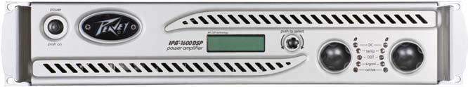
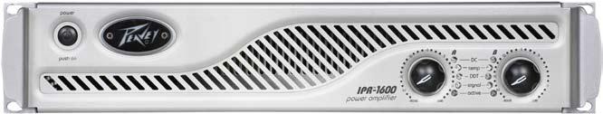
4 IPR 1600/3000/4500/6000 Power Amplifier ENGLISH Congratulations on your purchase of an IPR power amplifier, designed for years of reliable, flawless operation under rigorous use. The groundbreaking IPR series utilizes an advanced design that allows Peavey engineers to dramatically reduce weight while increasing output power, reliability and thermal efficiency. IPR Series amplifiers are designed with a resonant switch-mode power supply and a high-speed class D topology that yields the highest audio resolution and efficiency available. This revolutionary amplifier offers the sonic superiority and unsurpassed reliability for which Peavey is famous, in an extremely efficient and lightweight design. Advanced technology and extensive protection circuitry allow operation with greater efficiency into difficult loads and power conditions. The DDT (Distortion Detection Technique) circuitry ensures trouble-free operation into loads as low as 2 ohms. DDT protects drivers and ensures that sonic integrity is maintained, even in extreme overload conditions. The IPR s high-efficiency design allows the amplifier to operate at very low temperatures, and does not require massive heat sinks to cool. For your safety, read the important precautions section, as well as input, output and power connection instructions. Although the IPR amplifier is simple to operate and housed in an ultra-strong, ultra-lightweight chassis, improper use can be dangerous. This amplifier is very highpowered and can put out high voltages and sizable currents at frequencies up to 30 khz. Always use safe operating techniques when operating this amplifier. Before you send signal through your amplifier, it is very important to ensure that the product has the proper AC line voltage supplied. You can find the proper voltage for your amp printed next to the IEC line (power) cord on the rear panel of the unit. Each product feature is numbered. Refer to the front-panel diagram in this manual to locate the particular features next to its number. Please read this guide carefully to ensure your personal safety as well as the safety of your amplifier. AC POWER SWITCH Features: 2 channel independent, fourth-order Linkwitz-Riley crossovers 4 pole twist lock output connectors DDT protection Ultra-light weight Revolutionary IPR class D topology Individual signal pass 1/4 jacks on each channel Detented input controls LED illuminated Combination XLR 1/4 inputs Standby, LED power present indication VENTILATION: For proper ventilation, allow 12" clearance from nearest combustible surface. Make sure that vents are not blocked and air can flow freely through the unit. WARNING: Changes or modifications to this unit not expressly approved by the party responsible for compliance could void the user's authority to operate the equipment. NOTE: This equipment has been tested and found to comply with the limits for a Class B digital device, pursuant to Part 15 of the FCC Rules. These limits are designed to provide reasonable protection against harmful interference in a residential installation. This equipment generates, uses and can radiate radio frequency energy and if not installed and used in accordance with the instructions, may cause harmful interference to radio communications. However, there is no guarantee that interference will not occur in a particular installation. If this equipment does cause harmful interference to radio or television reception, which can be determined by turning the equipment off and on, the user is encouraged to try to correct the interference by one or more of the following measures: Reorient or relocate the receiving antenna. Increase the separation between the equipment and receiver. Connect the equipment into an outlet on a circuit different from that to which the receiver is connected. Consult the dealer or and experienced radio/tv technician for help. 7
 in standby mode, indicating AC power has been connected to the amplifier but the amplifier has not yet been turned on.")
5 Front Panel This button triggers the relay that provides power to the amplifier. This unique power switch will glow blue (along with the Peavey logo) in standby mode, indicating AC power has been connected to the amplifier but the amplifier has not yet been turned on. INDICATORS The IPR amplifiers feature five front-panel LED indicators per channel: ACTIVE, SIGNAL, DDT, TEMP and DC. These LED indicators inform the user of each channel s operating status and warn of possible abnormal conditions. ACTIVE LED The Active LED indicates that its channel s output relay is closed and the channel is operational. It lights under normal operation and remains on, even when the channel is in DDT gain reduction. These protection features leave the output relay closed. If the Active LED goes off, there is no signal at the output connectors. SIGNAL LED This LED lights when its channel produces an output signal of about 4 volts RMS or more (0.1 volt or more at the input, with 0 db attenuation and standard x40 voltage gain). This signal indicates whether a signal is reaching and being amplified by the amplifier. DDT (DISTORTION DETECTION TECHNIQUE) LED A channel s DDT LED will light at the onset of clipping. If the LEDs are flashing quickly and intermittently, the channel is just at the clip threshold. A steady, bright glow means the amp is clip limiting, or reducing gain to prevent severely clipped waveforms from reaching the loudspeakers. See the Distortion Detection Technique section for more information. During initial power-up the DDT LED will light to indicate that the RAMPUP gain reduction circuitry is activated. This prevents sudden signal bursts when the speaker relays are closed. TEMP LED In the unlikely event of an unstable thermal condition, amplifier protection will be activated and will shut down the offending channel. The Temp LED will remain illuminated until safe operating temperatures have returned. DC LED In the event of abnormal operating conditions, the IPR has built-in amplifier protection. Under conditions that would normally damage the power amplifier, the DC LED will illuminate and the channel will automatically attempt to restart to correct the condition. If the amplifier does not return to normal operating status, contact your local authorized service center. INPUT ATTENUATORS Whenever possible, set the attenuators fully clockwise to maintain optimum system headroom. The input attenuator controls, located at the front panel (one for channel A, one for channel B), adjust gain for their respective amplifier channels in all modes. See the specifications at the end of this manual for standard voltage gain and input sensitivity information. 2 8
6 Rear Panel AC POWER INLET: This is the receptacle for an IEC line cord, which provides AC power to the unit. Connect the line cord to this connector to provide power to the unit. Damage to the equipment may result if improper line voltage is used. (See line voltage marking on unit) Never break off the ground pin on any equipment. It is provided for your safety. If the outlet used does not have a ground pin, a suitable grounding adapter should be used and the third wire should be grounded properly. To prevent the risk of shock or fire hazard, always make sure that the amplifier and all associated equipment is properly grounded. NOTE: FOR U.K. ONLY As the colors of the wires in the mains lead of this apparatus may not correspond with the colored markings identifying the terminals in your plug, proceed as follows: (1) The wire which is colored green and yellow must be connected to the terminal which is marked by the letter E, or by the Earth symbol, or colored green or green and yellow. (2) The wire which is colored blue must be connected to the terminal which is marked with the letter N, or the color black. (3) The wire which is colored brown must be connected to the terminal which is marked with the letter L, or the color red. CHANNEL MODE SWITCH HIGH PASS This position is used to activate the HIGH PASS filter for the corresponding channel. This Linkwitz -Riley filter will limit the frequencies sent to the associated amplifier channel to those frequencies above 100 Hz. In situations where separate subwoofer cabinets are being used, this position would indicate connecting the mid-high frequency speaker cabinet to the channel associated with the HIGH PASS switch. FULL RANGE As the name implies, the Full Range position on this switch allows all frequencies to pass to the amplifier. Normally used when connecting a full range speaker enclosure to the amplifier's output. SUBWOOFER This position is used to activate the LOW PASS filter for the corresponding channel. This Linkwitz-Riley filter will limit the frequencies sent to the associated amplifier channel to those frequencies below 100 Hz. In situations where separate subwoofer cabinets are being used, this position would indicate connecting the subwoofer speaker cabinet to the channel associated with the Subwoofer switch. 9

7 Rear Panel THRU/OUT JACKS This 1/4 jack supplies parallel output signals from the associated channel for patching to this amplifier and/or additional power amplifier inputs. The Thru/Out jack is affected by the position of the associated Channel Mode switch. This 1/4 jack also provides an unbalanced (tip/sleeve) output to be patched with single-conductor shielded cables. CONNECTING INPUTS Input connections are made via the 3-pin XLR (pin 2+) or 6.3 mm plug combination connectors on the rear panel of the amplifier. The inputs are actively balanced. The input overload point is high enough to accept the maximum output level of virtually any signal source. CONNECTING OUTPUTS All models have one combination 4 pole twist lock output connector per channel. While a 1/4 speaker cable may be connected to this output, the 4 pole twist lock output connection is the preferred method. CIRCUIT BREAKER In the unlikely event of operating conditions that may potentially damage the amplifier, the circuit breaker may trip. After inspecting the cables and connections, the amplifier can be reset. If the circuit breaker trips a second time, contact the local Peavey authorized service center. 10
8 IPR 1600/3000/4500/6000 DSP Power Amplifier ENGLISH As the name implies, the IPR 1600, 3000, 4500, and 6000 DSP all include advanced digital signal processing. The DSP was designed to be incredibly effective, yet extremely easy to use. Using unique and revolutionary advanced bass enhancement processes, the IPR DSP amplifiers dramatically improve the perceived level of bass in any system, using a fraction of the power that would be required with any other power amp. Before you send signal through your amplifier, it is very important to ensure that the product has the proper AC line voltage supplied. You can find the proper voltage for your amp printed next to the IEC line (power) cord on the rear panel of the unit. Each product feature is numbered. Refer to the front panel diagram in this manual to locate the particular features next to its number. Please read this guide carefully to ensure your personal safety as well as the safety of your amplifier. IPR DSP Features: DDT protection Revolutionary IPR class D topology Detented input controls Combination XLR 1/4 inputs Combination 1/4 or 1/4 4 pole twist lock output connector Light weight Individual signal pass-thru 1/4 jacks on each channel LED illuminated DSP-based Loudspeaker Management System 120 ms of delay per channel 4 bands of parametric equalization per channel Security lock Adjustable fourth-order Linkwitz-Riley Crossover Adjustable fourth-order high-pass filter each channel Setup wizard MAXX Bass Horn EQ each channel Blue, backlit LCD screen WARNING: PLEASE REVIEW YOUR DSP SETTINGS BEFORE SENDING SIGNAL TO THE AMPLIFIER. INCORRECT SETTINGS CAN POTENTIALLY DAMAGE SPEAKER ENCLOSURES. We have made every attempt to ensure the Setup Wizard will help correctly configure the DSP; however, incorrect settings at any point of the setup process can damage your speaker enclosures. If you have any questions, please no not hesitate to call our customer service line. VENTILATION: For proper ventilation, allow 12" clearance from nearest combustible surface. Make sure that vents are not blocked and air can flow freely through the unit. WARNING: Changes or modifications to this unit not expressly approved by the party responsible for compliance could void the user's authority to operate the equipment. NOTE: This equipment has been tested and found to comply with the limits for a Class B digital device, pursuant to Part 15 of the FCC Rules. These limits are designed to provide reasonable protection against harmful interference in a residential installation. This equipment generates, uses and can radiate radio frequency energy, and if not installed and used in accordance with the instructions, may cause harmful interference to radio communications. However, there is no guarantee that interference will not occur in a particular installation. If this equipment does cause harmful interference to radio or television reception, which can be determined by turning the equipment off and on, the user is encouraged to try to correct the interference by one or more of the following measures: Reorient or relocate the receiving antenna. Increase the separation between the equipment and receiver. Connect the equipment into an outlet on a circuit different from that to which the receiver is connected. Consult the dealer or and experienced radio/tv technician for help. 11
.")
 If there are currently stored manual settings in the DSP, the LCD screen will read CLEAR MANUAL EQ SETTINGS?")
9 Getting Started with DSP To navigate through the menus on the LCD screen, simply use the push-button navigation encoder located to the right of the LCD screen. The quickest and easiest way to configure any IPR DSP model is to use the Setup Wizard. After switching the unit on, the IPR DSP will display the Setup Wizard entry screen for 6 seconds (Fig. 1). Turn the encoder to "Yes" and depress to enter the Setup Wizard. If no input is received after six seconds, the screen will advance to the main operating menu. Fig. 1 SETUP WIZARD (Fig. 2) If there are currently stored manual settings in the DSP, the LCD screen will read CLEAR MANUAL EQ SETTINGS? This warning indicates there have been changes made to the DSP in manual mode and continuing through the Setup Wizard will erase the previously stored settings. To continue through the wizard, select YES. Selecting NO will leave the Setup Wizard and advance to the main operating menu. Fig. 2 Speaker Selection The first screen in the Setup Wizard allows the user to select the speaker associated with each channel of the amplifier. Rotate the navigation encoder and press to select the speaker for each channel. By selecting the speaker associated with each channel, the IPR DSP can make certain assumptions and create optimal settings for most circumstances with very little input from the user. The IPR DSP includes a library of Peavey speakers, as well as some generic selections for non-peavey speakers. (Fig. 3) After selecting speakers for each channel, if a subwoofer has not been selected, the user will be prompted with, DOES THE SYSTEM HAVE A SUBWOOFER? If Yes is selected, the amplifier will assume it is part of a two-way system with another amplifier operating the subwoofer. The IPR DSP will then assign a 100 Hz crossover to each channel, allowing only those frequencies above 100 Hz to pass to the speaker cabinets attached to the amplifier. If a subwoofer was selected during the setup process, the amplifier will automatically assign the appropriate crossover to each channel. Fig. 3 Fig. 4 Note: In the Setup Wizard the crossover is automatically set at 100 Hz. Enter Manual mode to adjust crossover frequency. (Fig. 4) 12

. In other words, both channels will receive the signal coming from channel A.")
10 Setup Wizard Setup Wizard Input Mode Select: The IPR DSP has the capability of routing the signal coming into channel A to channel B for Mono operation. In the event the user selects a mid-high cabinet for one channel and a subwoofer for the other channel, the IPR DSP will make the assumption the amplifier is being used in Mono and will route the signal coming into channel A to channel B, as well. Otherwise, the user will be prompted to select the Input mode of operation. Mono, as described above, will send the signal coming from input A to both the A and B amplifiers. (Fig. 5). In other words, both channels will receive the signal coming from channel A. In Stereo mode, each channel will receive an independent input. Amplifier A will use input A and amplifier B will get signal from Input B (Fig. 6). Keep in mind the A and B 1/4 thru outputs are connected in parallel with the A and B input connectors, respectively. This is extremely helpful when running multiple amplifiers. To preserve the balanced input when using the thru output, use a TRS (Stereo) 1/4" cable. Fig. 5 Fig. 6 Any of these settings can be changed in Manual mode. 13

.")
: Rock Dance Thump DJ Contemporary Worship Speech Fig. 7 Fig. 8 Setup Wizard Remote Speaker Delay Delay is often required for systems with remote speakers.")
11 Setup Wizard SETUP WIZARD EQ EQ (or equalization) is designed to either make corrections to the audio signal based on frequency anomalies in a particular room, or to color the audio signal to adjust for a specific application. Many of these application-style EQs color the signal path to represent the EQ curve that would be typically associated with a style of music or a specific application (such as speech). After speaker cabinet selection, the IPR DSP will ask the user if EQ is required (Fig. 7). If Yes is selected the user will be able to scroll through several pre-designed EQ curves that will give the user the general characteristics associated with one of the following selections (Fig. 8): Rock Dance Thump DJ Contemporary Worship Speech Fig. 7 Fig. 8 Setup Wizard Remote Speaker Delay Delay is often required for systems with remote speakers. Occasionally remote speakers are required for larger audiences. These speakers can provide additional coverage in areas the main PA speakers do not adequately cover. Unless the remote speakers are delayed properly the audience will notice a time difference between the primary source (main PA) and remote speaker. This time difference will be perceived as an echo and will cause an undesirable listening environment. The IPR DSP amplifiers offer up to 120 ms of delay per channel, enough to position the remote speakers up to 136 ft from the primary PA speakers (Fig. 9). Fig. 9 When the amplifier is configured to drive a Mono, two-way speaker system, the delay adjustment changes both channels simultaneously. Once in the delay screen, turn the navigation encoder to increase or decrease the amount of delay. The screen displays the delay in milliseconds, feet and meters (Fig. 10). Fig

12 Setup Wizard Setup Wizard Lock Settings: The IPR DSP allows the user to safely lock the settings of the amplifier after they have been configured. This feature can be extremely useful when using the IPR DSP in an installation environment, preventing unwanted changes to the settings that can potentially damage the speakers. The user can chose whether to disable the security lock, lock all of the settings, or ALL of the settings EXCEPT the volume controls (input attenuators) (Fig.11). If the security lock is engaged, users will be prompted to enter the security code before being able to edit any of the DSP settings. Once the correct access code has been entered, the control screen will remain unlocked until the user either completes the Setup Wizard or returns to the main menu (Fig.12). Please contact Customer Service if the lock code is forgotten or misplaced. Fig. 11 NOTE: The IPR DSP input attenuators are actually encoders, unlike the non-dsp version of the IPR, and are controlled by DSP. Fig

.")
13 Main Menu Fig. 13 Scroll through menu using navigation encoder Main Menu Settings The Main Menu is divided into six sections, accessible by scrolling right or left through the Main Menu options using the navigation encoder (Fig. 13). Each menu item displays its current status. Press the encoder over the selection to edit. MODE The IPR DSP has the capability of routing the signal coming into input A to both amplifiers A and B for Mono operation (Fig. 14). In Mono mode, both channels will receive the signal coming in from channel A. In Stereo mode, each channel will receive and independent input. Amplifier A will use input A, and amplifier B will use input B (Fig. 15). Fig. 14 Keep in mind the 1/4 thru outputs can be used to route their respective input signals to other to other amplifiers. This is extremely helpful when in sound systems with amplifiers. To preserve the balanced input when using the thru output, use a TRS (stereo) 1/4" cable to route the "thru" signal to another balanced input. Fig. 15 Volume Volume: The Main Menu displays the current settings for the volume controls (0 being maximum) (Fig. 16) NOTE: The volume controls are really input attenuators and are controlled by DSP. Whenever possible, set the attenuators to maximum (0) to maintain optimum system headroom. The input attenuator controls, located on the front panel (one for channel A, one for channel B), adjust gain for their respective amplifier channels in all modes. See the specifications at the end of this manual for standard voltage gain and input sensitivity information. 16 Fig. 16
. Fig.")

14 Crossover Crossover The Main Menu displays the status of the crossover associated with each channel, either OFF, HI or LOW. In the case of this illustration, channel A indicates high frequencies are passing onto amplifier A. Channel B indicates low frequencies are passing onto amplifier B (Fig. 17). Fig. 17 To adjust the crossover, press the navigation encoder while the cursor is highlighting XVR. NOTE: INCORRECT CROSSOVER SETTINGS MAY DAMAGE YOUR SPEAKERS! Use speaker manufacturer s recommended settings to avoid potential damage. Crossover Edit mode allows the user to remove, add or adjust the crossover point. Select the desired crossover frequency and press the navigation encoder (Fig. 18). To turn OFF the crossover function, lower the crossover frequency until "None - Full Range" appears on the screen. Fig. 18 Once the crossover frequency has been selected, set the frequency range that channels A and B each receive. Press the navigation encoder to select and advance (Fig. 19). These screens will not appear if the crossover is turned off. Fig. 19 The next menu allows the selection of a high-pass filter for each channel. This filter reduces unwanted, potentially energy-robbing low-end frequencies from entering the system (Fig. 20). Setting an appropriate high-pass filter frequency also helps protect the loudspeaker from damage and adjusts the frequency range of the Maxx bass processor. Fig
. Fig. 21 After entering Edit mode, the user will be able to activate or deactivate the EQ on each channel.")
. Fig.")
15 EQ EQ The EQ section of the Main Menu indicates whether the EQ is active on each channel. Pressing the navigation encoder when the cursor highlights EQ will enter EQ Edit mode. Each channel has 4 parametric EQs, horn equalization and enhanced bass processing (Fig. 21). Fig. 21 After entering Edit mode, the user will be able to activate or deactivate the EQ on each channel. Press the navigation encoder to move the cursor from EQ to channel A, then select ON or BYPASS. Repeat for channel B (Fig. 22). Turn the navigation encoder to the right to navigate to the BASS ENHANCEMENT SCREEN. Press and select to adjust the amount of BASS ENHANCEMENT (Fig. 23). Fig. 22 MaxxBass uses psycho-acoustics to calculate precise harmonics that are related to the fundamental tones of sound. The harmonics are generated mostly from low-bass that is below the high-pass filter setting. When these harmonics are combined, it creates the effect of lower, deeper frequencies. Extends perceived bass response by up to 1.5 octaves Preserves the dynamic range and character of the original bass Fig
16 Parametric EQ Parametric equalizers allow precise control of the amplitude, center frequency and bandwidth of these bell response filters. Each channel of the amplifier has four bands of parametric EQ. These EQs can be used to compensate for peaks and dips in the frequency response of certain speakers, eliminate feedback, and reduce or enhance any area of the frequency spectrum. The attached frequency diagram will help identify the frequencies that may need to be adjusted. Each parametric EQ has three adjustable parameters: Fig. 24 Amplitude: the level of increase or decrease in decibels (cut or boost up to 15 db) Frequency: the center frequency of the bandwidth being adjusted. Bandwidth: the width of the frequency band being adjusted. The bandwidth control is adjustable from a narrow 3/10 of an octave for precise filtering to a wide 2 octaves for broad control. To adjust each EQ simply scroll to the desired EQ and press the navigation encoder to adjust each parameter (Fig. 24). Repeat for each of the four EQs on channel A and B. HORN EQ The horn equalization in the IPR DSP provides a gentle, rising high-frequency boost to compensate for the roll-off inherent to most high frequency horns. Adjust the frequency and level to achieve the desired response. (Fig. 25) Fig
17 Delay Delay: The Delay screen on the Main Menu indicates how much delay is present on each channel in milliseconds. To enter Delay Edit mode, highlight DLY with the cursor and press the navigation encoder (Fig. 26). Delay is often required for systems with remote speakers. Occasionally remote speakers are required for larger audiences. These speakers can provide additional coverage in areas that the main PA speakers are not adequate. Unless the remote speakers are delayed properly, the audience will notice a time difference between the primary source (main PA) and remote speaker. This time difference will be perceived as an echo and will cause an undesirable listening environment. The IPR DSP amplifiers offer up to 120 ms of delay per channel, enough to position the remote speakers up to 136 ft from the primary PA speakers. Fig. 26 Once in the delay screen, turn the navigation enconder to increase or decrease the amount of delay. The screen displays the delay in milliseconds, feet and meters. 20

18 Lock Settings Lock Settings: The IPR DSP allows the user to safely lock the settings of the amplifier (Fig. 27). This feature can be extremely useful when using the IPR DSP in an installation environment, preventing unwanted persons from changing the settings and potentially damaging the speakers. The user can choose to disable the security lock, lock ALL DSP settings, or lock ALL of the settings EXCEPT the volume controls (input attenuators). If the security lock is engaged, users will be prompted to enter the security code before being able to edit any of the DSP settings. The control screen will automatically relock when the user returns to the main menu. Please contact Customer Service if the lock code is forgotten or misplaced. Fig. 27 After selecting the type of lock, set a four-digit security code to engage the security feature. It is always best to record the access code in a safe place for future reference. AUTOMATIC STORAGE OF DSP SETTINGS When using the Setup Wizard, audio processing is not changed and the settings are not stored until setup is complete. None of the Wizard settings will be stored if the amplifier is turned off before completing the Wizard setup. The amplifier will return to previous settings when next powered on. When manually editing DSP parameters, the DSP processing will reflect changes as they are made. Changes are then automatically stored by returning to the Main Menu. Turning off the power before returning to the Main Menu will erase the changes made and return to the previous settings. 21
19 IPR 1600 Specification Sheet Rated Power (2 x 2 ohms) watts per 1 khz at <0.1% T.H.D. both channels driven. Rated Power (2 x 4 ohms) watts per 1 khz at <0.1% T.H.D. both channels driven. Rated Power (2 x 8 ohms) watts per 1 khz at <0.1% T.H.D. both channels driven. Rated Power (1 x 2 ohms) khz at <0.1% T.H.D. Rated Power (1 x 4 ohms) khz at <0.1% T.H.D. Rated Power (1 x 8 ohms) khz at <0.1% T.H.D. Minimum Load Impedance - 2 ohms Maximum RMS Voltage Swing - 55 volts Frequency Response - 10 Hz - 50 khz; +0, -3 db at 1 watt T.H.D. (2 x 2 ohms) watts per channel from 20 Hz to 1.5 khz, decreasing to 500 watts at 20 khz at <0.25% T.H.D. (2 x 4 ohms) watts per channel from 20 Hz to 20 khz T.H.D. (2 x 8 ohms) watts per channel from 20 Hz to 20 khz Input CMRR - > khz Voltage Gain - x 60 (+35 db) Crossover Hz switchable 2nd order High pass and 3rd order Low Pass per channel Crosstalk - > khz at 100 watts 4 ohms Hum and Noise - > -105 db, "A" weighted referenced to rated 4 ohms Damping Factor (8 ohms) - > 20 Hz - 1 khz at 8 ohms Phase Response - +9 to - 86 degrees from 20 Hz to 20kHz Slew Rate: - > 12V/us Input Sensitivity volts +/- 3% for 1 khz 4 ohm rated power,.68 volts +/- 3% for 1 khz. 2 ohm rated power Input Impedance - 15k ohms, balanced and 7.5k ohms unbalanced. Current 1/8 power ohms, ohms, ohms Current 1/3 power -1,160 2 ohms, ohms, ohms Cooling - Temperature dependent variable speed 80 mm DC fan Controls - 2 front panel attenuators, crossover select switch for H.P.F, Normal and L.P.F. Indicator LEDs - 2 DDT (clip limiting), 2 Signal presence, 2 Active status, 2 Temp and 2 DC protect Protection - Thermal, DC, subsonic, incorrect loads, under and over voltage Connectors - Inputs: Dual Combi 1/4 XLR, Outputs: Dual 1/4 signal patch, dual Speakon connectors Construction thick aluminum Dimensions x19 x 10.5 behind front panel for handle Dimensions Packed x20.8 x (120mm x 530mm x 316mm) Net Weight* kg (7.125 lbs.) Gross Weight kg (9.5 lbs.) Warranty - 5 years Rated power readings made with BW: <10 Hz to 22 khz. All power measurements made at 120 VAC and 240VAC. 2 ohm power is time limited by circuit breaker. *Net Weight does not include power cord. 22
20 PEAVEY ELECTRONICS CORPORATION LIMITED WARRANTY Effective Date: September 5, 2007 What This Warranty Covers Your Peavey Warranty covers defects in material and workmanship in Peavey products purchased and serviced in the U.S.A. and Canada. What This Warranty Does Not Cover The Warranty does not cover: (1) damage caused by accident, misuse, abuse, improper installation or operation, rental, product modification or neglect; (2) damage occurring during shipment; (3) damage caused by repair or service performed by persons not authorized by Peavey; (4) products on which the serial number has been altered, defaced or removed; (5) products not purchased from an Authorized Peavey Dealer. Who This Warranty Protects This Warranty protects only the original retail purchaser of the product. How Long This Warranty Lasts The Warranty begins on the date of purchase by the original retail purchaser. The duration of the Warranty is as follows: Product Category Guitars/Basses, Amplifiers, Pre-Amplifiers, Mixers, Electronic Crossovers and Equalizers Drums Enclosures Digital Effect Devices Microphones Speaker Components (incl. speakers, baskets, drivers, diaphragm replacement kits and passive crossovers) Tubes and Meters Cables Duration 2 years (+ 3 years)* 2 years (+ 1 year)* 2 years (+ 3 years)* 1 year (+ 1 year)* 2 years 1 year 90 days Limited Lifetime [*Denotes additional warranty period applicable if optional Warranty Registration Card is completed and returned to Peavey by original retail purchaser within 90 days of purchase.] What Peavey Will Do We will repair or replace (at Peavey's discretion) products covered by warranty at no charge for labor or materials. If the product or component must be shipped to Peavey for warranty service, the consumer must pay initial shipping charges. If the repairs are covered by warranty, Peavey will pay the return shipping charges. How To Get Warranty Service (1) Take the defective item and your sales receipt or other proof of date of purchase to your Authorized Peavey Dealer or Authorized Peavey Service Center. OR (2) Ship the defective item, prepaid, to Peavey Electronics Corporation, International Service Center, 412 Highway 11 & 80 East, Meridian, MS Include a detailed description of the problem, together with a copy of your sales receipt or other proof of date of purchase as evidence of warranty coverage. Also provide a complete return address. Limitation of Implied Warranties ANY IMPLIED WARRANTIES, INCLUDING WARRANTIES OF MERCHANTABILITY AND FITNESS FOR A PARTICULAR PURPOSE, ARE LIMITED IN DURATION TO THE LENGTH OF THIS WARRANTY. Some states do not allow limitations on how long an implied warranty lasts, so the above limitation may not apply to you. Exclusions of Damages PEAVEY'S LIABILITY FOR ANY DEFECTIVE PRODUCT IS LIMITED TO THE REPAIR OR REPLACEMENT OF THE PRODUCT, AT PEAVEY'S OPTION. IF WE ELECT TO REPLACE THE PRODUCT, THE REPLACEMENT MAY BE A RECONDITIONED UNIT. PEAVEY SHALL NOT BE LIABLE FOR DAMAGES BASED ON INCONVENIENCE, LOSS OF USE, LOST PROFITS, LOST SAVINGS, DAMAGE TO ANY OTHER EQUIPMENT OR OTHER ITEMS AT THE SITE OF USE, OR ANY OTHER DAMAGES WHETHER INCIDENTAL, CONSEQUENTIAL OR OTHERWISE, EVEN IF PEAVEY HAS BEEN ADVISED OF THE POSSIBILITY OF SUCH DAMAGES. Some states do not allow the exclusion or limitation of incidental or consequential damages, so the above limitation or exclusion may not apply to you. This Warranty gives you specific legal rights, and you may also have other rights which vary from state to state. If you have any questions about this warranty or service received or if you need assistance in locating an Authorized Service Center, please contact the Peavey International Service Center at (601) Features and specifications subject to change without notice. Logo referenced in Directive 2002/96/EC Annex IV (OJ(L)37/38, and defined in EN 50419: 2005 The bar is the symbol for marking of new waste and is applied only to equipment manufactured after 13 August
21 Features and specifications subject to change without notice. Peavey Electronics Corporation 5022 Hartley Peavey Drive Meridian, MS (601) FAX (601)
PV 231EQ Graphic Equalizer
 PV 231EQ Graphic Equalizer For more information on other great Peavey products, visit your local Peavey dealer or go online to www.peavey.com Intended to alert the user to the presence of uninsulated dangerous
Operating Manual
 PVi 4B 100-WATT 4-CHANNEL MIXER AMPLIFIER Operating Manual www.peavey.com Intended to alert the user to the presence of uninsulated dangerous voltage within the product s enclosure that may be of sufficient
Operating Manual
 PV i 8B 150-Watt, 8-Channel Mixer Amplifier Operating Manual www.peavey.com Intended to alert the user to the presence of uninsulated dangerous voltage within the product s enclosure that may be of sufficient
Operating Manual
 Classic 30 GUITAR AMPLIFIER Operating Manual www.peavey.com Intended to alert the user to the presence of uninsulated dangerous voltage within the product s enclosure that may be of sufficient magnitude
For more information on other great Peavey products, go to your local Peavey dealer or online at
 KB 1 Keyboard Amplifier Operation Manual For more information on other great Peavey products, go to your local Peavey dealer or online at www.peavey.com. Intended to alert the user to the presence of uninsulated
Operation Manual
 6505 + Operation Manual For more information on other great Peavey products, go to your local Peavey dealer or online at www.peavey.com. 1 Intended to alert the user to the presence of uninsulated dangerous
Operating Manual
 PV 6 and PV 6 USB Compact Mixers Operating Manual www.peavey.com Intended to alert the user to the presence of uninsulated dangerous voltage within the product s enclosure that may be of sufficient magnitude
Joe Satriani Signature All-Tube Amplifier
 JSX Joe Satriani Signature All-Tube Amplifier For more information on other great Peavey products, visit your local Peavey dealer or go online at www.peavey.com Intended to alert the user to the presence
Operating Manual
 PV 8 and PV 8 USB Compact Mixers Operating Manual www.peavey.com Intended to alert the user to the presence of uninsulated dangerous voltage within the product s enclosure that may be of sufficient magnitude
GPS Series Operation Manual
 GPS Series Operation Manual For more information on other great Peavey products, go to your local Peavey dealer or online at www.peavey.com. Intended to alert the user to the presence of uninsulated dangerous
A-16D A-Net Distributor
 A-16D A-Net Distributor For use with the Personal Monitor Mixing System Information in this document is subject to change. All rights reserved. Copyright 2003 Aviom, Inc. Printed in USA Document Rev. 1.03
DA216S DISTRIBUTION AMPLIFIER
 DISTRIBUTION AMPLIFIER IMPORTANT SAFETY INSTRUCTIONS 1. Read these instructions. 2. Keep these instructions. 3. Heed all warnings. 4. Follow all instructions. 5. Do not use this apparatus near water. 6.
MAX Series Bass Amplifiers
 MAX Series Bass Amplifiers Operating Manual www.peavey.com FCC Compliancy Statement This device complies with Part 15 of the FCC rules. Operation is subject to the following two conditions: (1) this device
P C X - V 1 2. True diversity VHF wireless receiver OPERATING GUIDE
 P C X - V 1 2 True diversity VHF wireless receiver OPERATING GUIDE Intended to alert the user to the presence of uninsulated dangerous voltage within the product s enclosure that may be of sufficient magnitude
WX-1 & WX-3 OPERATING MANUAL AND USER GUIDE. Professional Power Amplifier. WX-1 and WX-3.indd :23:16
 WX-1 & WX-3 Professional Power Amplifier OPERATING MANUAL AND USER GUIDE 3 www.wharfedalepro.com WX-1 and WX-3.indd 1 2014-7-16 10:23:16 TABLE OF CONTENTS TABLE OF CONTENTS... 1 IMPORTANT WARNINGS & SAFETY
A Channel Amplifier
 Installation Manual A2150 2 Channel Amplifier Table of Contents Installation Requirements and Recommendations 1 What s included 1 Speaker Wire Recommendations 1 Setup 2 Rack Mounting 2 Individually Protected
HTA125A/250A. Power Amplifiers. Installation & Use Manual
 HTA125A/250A Power Amplifiers Installation & Use Manual Specifications subject to change without notice. 2010 Bogen Communications, Inc. All rights reserved. 54-5832-04B 1011 NOTICE: Every effort was made
CS 1200H Operations Manual
 CS 1200H Operations Manual power amplifier For more information on other great Peavey products, go to your local Peavey dealer or online at www.peavey.com Intended to alert the user to the presence of
Cover for MMA 800T 1
 Cover for MMA 800T 1 Intended to alert the user to the presence of uninsulated "dangerous voltage" within the product's enclosure that may be of sufficient magnitude to constitute a risk of electric shock
SANPERA I. Player`s Handbook
 SANPERA I SANPERA I Player`s Handbook TM SANPERA I Welcome Thank you for purchasing the SanperaTM I foot controller for your VYPYR amplifier. We are certain you will enjoy having the control of your VYPYR
Cover for IPA 75/150T II
 Cover for IPA 75/150T II 1 Intended to alert the user to the presence of uninsulated "dangerous voltage" within the product's enclosure that may be of sufficient magnitude to constitute a risk of electric
N a s h v i l l e O p e r a t i n g G u i d e
 Nashville 1000 Operating Guide Intended to alert the user to the presence of uninsulated dangerous voltage within the product s enclosure that may be of sufficient magnitude to constitute a risk of electric
Classic Series Public Address Amplifiers C10 & C20 Models
 Classic Series Public Address Amplifiers C10 & C20 Models Installation and Use Manual 2009 Bogen Communications, Inc. All rights reserved. Specifications subject to change without notice. 54-5978-01B 0901
UA ª 35T II Utility Amplifier OPERATING INSTRUCTIONS
 OPERATING INSTRUCTIONS Intended to alert the user to the presence of uninsulated "dangerous voltage" within the product's enclosure that may be of sufficient magnitude to constitute a risk of electric
REVAMP4100 Instruction manual
 REVAMP4100 Instruction manual REVAMP4100 Instruction manual 3 REVAMP4100 manual 4 CLASS-D POWER AMPLIFIER IMPORTANT SAFETY INSTRUCTIONS 1. Read these instructions 2. Keep these instructions 3. Heed all
Model CC4041. CC Series Amplifier. Installation and Use Manual
 BASS 0 TREBLE 0-12 +12-12 +12 INPUT 1 INPUT 2 INPUT 3 INPUT 4 PEAK SIGNAL POWER POWER CC Series Amplifier Model CC4041 Installation and Use Manual 2012 Bogen Communications, Inc. All rights reserved. Specifications
PR 12P Powered bi-amplified two-way speaker system Operations Manual
 PR 12P Powered bi-amplified two-way speaker system Operations Manual For more information on other great Peavey products, go to your local Peavey dealer or online at www.peavey.com. Intended to alert the
XD-V30 Digital Wireless System
 XD-V30 Digital Wireless System Pilot s Handbook Manuel de pilotage Pilotenhandbuch Pilotenhandboek Manual del Piloto 取扱説明書 See www.line6.com/manuals for Advance Guide 40-00-0286 Advanced Users Guide available
Classic Series Public Address Amplifiers C10 & C20 Models
 Classic Series Public Address Amplifiers C10 & C20 Models Installation and Use Manual 2009 Bogen Communications, Inc. All rights reserved. Specifications subject to change without notice. 54-5978-01C 1106
FOR AVLEX ONLY MT-24A. User Guide. 2.4 GHz Digital Stationary Transmitter
 2.4 GHz Digital Stationary Transmitter User Guide All rights reserved. MN 017/05 Do not copy or forward without prior approvals MIPRO. Specifications and design subject to change without notice. 2 CE5
IPA 2300 Power Amplifer Owner s Manual
 1 IPA 2300 Power Amplifer Owner s Manual IPA 2300 Power Amplifier ENGLISH The IPA 2300 is a high-quality industrial-grade audio amplifier. Designed for flexibility in application this amplifier represents
IMPORTANT SAFETY INSTRUCTIONS
 Addendum IMPORTANT SAFETY INSTRUCTIONS Read these instructions. Keep these instructions. Heed all warnings. Follow all instructions. Do not use this apparatus near water. Mains powered apparatus shall
plifier D-501 otion Am Tactile M
 Tactile Motion Amplifier D-501 IMPORTANT SAFETY INSTRUCTIONS WARNING: 1. Read and keep these instructions for future reference. 2. Do not use this apparatus near water. 3. Clean only with a dry cloth.
DPA-1.2. Instruction Manual. 2 Channel Amplifier with Auto A/B Selector DPA-1.2 DPA-1.2 POWER SERIAL # LINE INPUT SENSING SPEAKER B OUT
 POWER Russound DPA-1.2 Instruction Manual 2 Channel Amplifier with Auto A/B Selector NEWMARKET, NH USA DPA-1.2 Russound 68835 Conforms to UL 6500 Certified to CSA C22.2 No1-94 DPA-1.2 Tested to Comply
Operating Manual
 Kosmos v pectrum Enhancement ystem Operating Manual www.peavey.com Intended to alert the user to the presence of uninsulated dangerous voltage within the product s enclosure that may be of sufficient magnitude
3400 Watt Stereo Power Amplifier
 3400 Watt Stereo Power Amplifier OWNER'S MANUAL Copyright 2014, Samson Technologies Corp. v1.1 Samson Technologies Corp. 45 Gilpin Ave Hauppauge, NY 11788 www.samsontech.com Important Safety Information
ECA COMMERCIAL AMPLIFIER OWNER S MANUAL ECA-70MIXAMP V / 70V / 4Ω Amplifier ECA-70MIXAMP-1-60 OUTPUT LEVEL POWER MASTER MIC 1
 OWNER S MANUAL ECA COMMERCIAL AMPLIFIER ECA-MIXAMP--6 V / V / Ω Amplifier TEMP PROT OUTPUT LEVEL ECA-MIXAMP--6 6 POWER MIC MIC MIC MIC AUX AUX BASS TREBLE 5 5 5 5 5 6 6 6 6 6 MASTER 5 6 ON OFF + - + -
REVAMP4120T Instruction manual
 REVAMP4120T Instruction manual REVAMP4120T Instruction manual 3 REVAMP4120T manual 4 CLASS-D POWER AMPLIFIER IMPORTANT SAFETY INSTRUCTIONS 1. Read these instructions 2. Keep these instructions 3. Pay
2BSST POWER AMPLIFIER OWNER S MANUAL
 2BSST POWER AMPLIFIER OWNER S MANUAL IMPORTANT SAFETY INSTRUCTIONS The lightning flash with arrowhead symbol within an equilateral triangle, is intended to alert the user to the presence of un-insulated
Classic Series Amplifiers C35, C60, & C100 Models
 Classic Series Amplifiers C35, C60, & C100 Models Installation and Use Manual 2009 Bogen Communications, Inc. All rights reserved. Specifications subject to change without notice. 54-5979-02E 1203 Notice:
TriFlex. Powered Subwoofer and Stereo Satellite System
 TriFlex Powered Subwoofer and Stereo Satellite System For more information on other great Peavey products, visit your local Peavey dealer or go online to www.peavey.com Intended to alert the user to the
Operating Manual
 PR 15 D Powered bi-amplified two-way speaker system Operating Manual www.peavey.com Intended to alert the user to the presence of uninsulated dangerous voltage within the product s enclosure that may be
NS-HDTUNE HD Radio Tuner
 NS-HDTUNE HD Radio Tuner HD Radio Tuner Contents Insignia NS-HDTUNE HD Radio Tuner Introduction.................................... 3 Safety information.............................. 4 Features........................................
Model CC4052. CC Series Amplifier. Installation and Use Manual
 CC Series Amplifier Model CC4052 Installation and Use Manual 2012 Bogen Communications, Inc. All rights reserved. Specifications subject to change without notice. 54-2216-01A 1303 NOTICE: Every effort
R-Series R235LS 2-Channel Power Amplifier with Local Source Switching
 R-Series R235LS 2-Channel Power Amplifier with Local Source Switching User s Manual On Off R235LS POWER A MPLIFIER IMPORTANT SAFEGUARDS WARNING TO REDUCE THE RISK OF FIRE OR ELECTRIC SHOCK, DO NOT EXPOSE
SPECIAL 6. 6-Watt Vacuum Tube Guitar Amplifier. User Manual
 SPECIAL 6 6-Watt Vacuum Tube Guitar Amplifier User Manual Table of Contents Table of Contents... 3 Product Safety Information...4 Panel Functions... 5 Technical Specifications... 8 Important Safety Instructions
Owners Manual Excite X14A
 Owners Manual Excite X14A Introduction Introduction Important safety instructions The lightning flash with an arrowhead symbol within an equilateral triangle, is intended to alert the user to the presence
REVAMP2250 Instruction manual
 REVAMP2250 Instruction manual REVAMP2250 Instruction manual 3 REVAMP2250 Manual 4 CLASS-D POWER AMPLIFIER IMPORTANT SAFETY INSTRUCTIONS 1. Read these instructions 2. Keep these instructions 3. Heed all
Dual Compressor/Expander/Limiter Operating Manual
 CEL-2A Dual Compressor/Expander/Limiter Operating Manual For more information on other great Peavey products, go to your local Peavey dealer or online at www.peavey.com Intended to alert the user to the
MODEL A1. PackLite TM POWER AMPLIFIER
 MODEL A1 PackLite TM POWER AMPLIFIER Svenska Nederlands Italiano Français Español Deutsch Dansk English Important Safety Instructions 1. Read these instructions. 2. Keep these instructions. 3. Heed all
Trace Elliot Elf Bass Instrument Amplifier
 Trace Elliot Elf Bass Instrument Amplifier Owner s Manual FCC Compliancy Statement This device complies with Part 15 of the FCC rules. Operation is subject to the following two conditions: (1) this device
Dual Alarm Clock Radio with Digital Tuning NRC-174. Instruction Manual Please read carefully before use and keep for future reference.
 Dual Alarm Clock Radio with Digital Tuning NRC-174 Instruction Manual Please read carefully before use and keep for future reference. Important Safety Information CAUTION RISK OF ELECTRIC SHOCK DO NOT
1695T Black Magick. User Manual
 1695T Black Magick User Manual All contents c Absara Audio LLC 2014 1. Important Safety Information The triangle surrounding an exclamation mark alerts users to the presence of important warnings or information.
AG30 USER S MANUAL.
 AG30 USER S MANUAL 30 WATT acoustic performance AMP FCC Statements 1. Caution: Changes or modifications to this unit not expressly approved by the party responsible for compliance could void the user s
INSTRUCTION MANUAL LCS TX
 INSTRUCTION MANUAL LCS TX 4 Channel Transmitter LCS1 Single Channel Transmitter Cardio Theater Inc Service 1-800-776-6695 Sales 1-800-CARDIO-1 1 Introduction CONGRATULATIONS on your choice of this product
KLASIK NEAR FIELD ACTIVE STUDIO MONITOR
 USER S MANUAL KLASIK NEAR FIELD ACTIVE STUDIO MONITOR CONTENTS page INTRODUCTION GENERAL INFORMATION 3 REAR PANEL REAR PANEL 4 INPUTS 5 SWITCHES 5 TECHNICAL SPECIFICATIONS TECHNICAL SPECIFICATIONS 7 SAFETY
HQ-31 HQ-15 USER S GUIDE SINGLE CHANNEL 31 BAND 1/3 OCTAVE GRAPHIC EQUALIZER DUAL CHANNEL 15 BAND 2/3 OCTAVE GRAPHIC EQUALIZER
 HQ-31 SINGLE CHANNEL 31 BAND 1/3 OCTAVE GRAPHIC EQUALIZER HQ-15 DUAL CHANNEL 15 BAND 2/3 OCTAVE GRAPHIC EQUALIZER USER S GUIDE GENERAL INFORMATION SINGLE CHANNEL 31 BAND 1/3 OCTAVE GRAPHIC EQUALIZER WITH
M-300 Mono power amplifier User s guide
 M-300 Mono power amplifier User s guide M-300 Mono power amplifier User s guide Specifications: Contents: Power output: 8Ω: 290W, 0.01% THD SPECIFICATIONS Page 2 Input impedance: Gain: 4Ω: 580W, 0.01%
STEREO POWER AMPLIFIER OWNER MANUAL PR-150 DESIGNED IN U.K. PDF created with FinePrint pdffactory trial version
 STEREO POWER AMPLIFIER OWNER MANUAL PR-150 DESIGNED IN U.K. INTRODUCTION Congratulations on your purchase of MA PR-150 Stereo Power Amplifier. The performance of PR-150 is perfect for any audio application,
Professional Power Amplifiers. AMERICAN AUDIO 4295 Charter Street Los Angeles Ca Revised 12/03. User Instructions
 Professional Power Amplifiers AMERICAN AUDIO 4295 Charter Street Los Angeles Ca. 90058 Revised 12/03 User Instructions This symbol is intended to alert the user to the presence of non insulated "dangerous
A W Table-Top Amplifier. with Built-in Bluetooth streaming
 A0361 100W Table-Top Amplifier with Built-in Bluetooth streaming 17 The A0361 Table-Top Amplifier can be used with Channel Vision s CAT5 audio hubs to provide a powerful 100 Watt Amplifier, 50Watts per
AG60 USER S MANUAL.
 AG60 USER S MANUAL 60 WATT acoustic PERFORMANCE SYSTEM FCC Statements 1. Caution: Changes or modifications to this unit not expressly approved by the party responsible for compliance could void the user
Tube Fusion II. OPERATING INSTRUCTIONS - Issue 1.1. Tube Fusion-II TF200-II TF300-II TF320-II TF700-II
 Tube Fusion II - Issue. Tube Fusion-II TF200-II TF300-II TF320-II TF700-II IMPORTANT SAFETY INSTRUCTIONS WARNING: When using electric products, basic cautions should always be followed, including the following..
CR31. Companion. Instruction Manual
 CR31 Companion Instruction Manual 910-244700-001 IMPORTANT SAFETY INSTRUCTION PLEASE READ CAREFULLY ALL THE FOLLOWING IMPORTANT SAFEGUARDS THAT ARE APPLICABLE TO YOUR EQUIPMENT 1. Read Instructions - All
Operating Manual
 Mini MAX Bass Amplifier Operating Manual www.peavey.com FCC/ICES Compliancy Statement This device complies with Part 15 of the FCC rules and Industry Canada license-exempt RSS Standard(s). Operation is
Warning: Electrical Hazard... 3 Safety Instruction Sheet for STG Product Overview What s in the box?... 4
 STG-2412 User Guide Warning: Electrical Hazard... 3 Safety Instruction Sheet for STG-2412... 3 Product Overview... 4 What s in the box?... 4 Using STG-2412 for Mixing, Processing, and Recording... 5 Software
EQ-AMP60 60W Mixer Amplifier
 EQ-AMP60 60W Mixer Amplifier Instruction Manual 4091 AMTC Center Drive Clearwater, FL 33764-6976 (727)531-3105 (727)531-3965 www.amtc.com Features 1. MIC 1 input with front- and rear-panel connectors 2.
Antidote. Manual. Model: ZA-35.
 Antidote Manual Model: ZA-35 www.drzamps.com This symbol warns the user of dangerous voltage levels localized within the enclosure. This symbol advises the user to read all accompanying literature for
POWERED SUBWOOFER V2218S
 TABLE OF CONTENTS Important Safety Instructions...3 Quick Start Guide...5 VâRi Series Back Panel...6 Specifications...7 Warranty/FCC Statements...8 WELCOME CONGRATULATIONS on your purchase of a Harbinger
XLS SERIES LOUD SPEAKERS
 XLS SERIES LOUD SPEAKERS User Manual CERWIN-VEGA S LIMITED WARRANTY WELCOME TO THE FAMILY! First off, you have great taste in loudspeakers. At Cerwin-Vega!, deep bass and great highs are a way of life.
THE NEW FACE OF BASS PRO BASS SYSTEM U30, U60, U120. Owner s Manual
 152420M-1 07/18 THE NEW FACE OF BASS Blackstar Amplification Ltd, Beckett House, 14 Billing Road, Northampton, NN1 5AW, UK For the latest information go to: www.blackstaramps.com PRO BASS SYSTEM U30, U60,
Instruction Manual Please read carefully before use and keep for future reference.
 Easy-Read Dual Alarm Clock with Daily Repeat, Bluetooth, and USB Charge Port NRC-181 Instruction Manual Please read carefully before use and keep for future reference. Important Safety Information CAUTION
AV30MX-2 Operation Manual
 AV30MX-2 Operation Manual 1 Important safety instructions 1. Please read carefully prior to product installation or operation. 2. Read these instructions. 3. Keep these instructions. 4. Heed all warnings.
MISTRAL 900/1500 STEREO POWER AMPLIFIER
 LTO R User's Manual MISTRAL 900/1500 STEREO POWER AMPLIFIER www.altoproaudio.com Version 1.0 OCT. 007 English IMPORTANT SAFETY INSTRUCTION CAUTION RISK OF ELECTRIC SHOCK DO NOT OPEN TO REDUCE THE RISK
Important Safety Information
 OWNER'S MANUAL Important Safety Information 1. Read these instructions. 2. Keep these instructions. 3. Heed all warnings. 4. Follow all instructions. 5. Do not use this apparatus near water. 6. Clean only
User Manual BUGERA Classic 150-Watt Hi-Gain Valve Amplifier Head. bugera-amps.com
 User Manual BUGERA 1960 Classic 150-Watt Hi-Gain Valve Amplifier Head 2 BUGERA 1960 User Manual Table of Contents Thank you... 2 Legal Disclaimer... 3 Limited Warranty... 3 Control elements... 5 Front
USER MANUAL APG DYNAMIC PROCESSORS MATRIX ARRAY SYSTEMS 4000SP 6000SP 9000SP
 USER MANUAL APG DYNAMIC PROCESSORS MATRIX ARRAY SYSTEMS 4000SP 6000SP 9000SP SAFETY INSTRUCTIONS This symbol, wherever it appears, alerts you to the presence of uninsulated dangerous voltage inside the
IMPORTANT SAFETY INSTRUCTIONS
 WR-1 Version 1 IMPORTANT SAFETY INSTRUCTIONS 1. 2. 3. 4. 5. 6. 7. 8. 9. Read these instructions. Keep these instructions. Heed all warnings. Follow all instructions. Do not use this apparatus near water.
HT-5. Owner s Manual. Designed and Engineered by Blackstar Amplification UK
 HT-5 Owner s Manual Designed and Engineered by Blackstar Amplification UK IMPORTANT SAFETY INSTRUCTIONS 1. Read these instructions. 2. Keep these instructions 3. Heed all warnings. 4. Follow all instructions.
441 DUAL CHANNEL 15 BAND 2/3 OCTAVE GRAPHIC EQUALIZER 451 SINGLE CHANNEL 31 BAND 1/3 OCTAVE GRAPHIC EQUALIZER
 441 DUAL CHANNEL 15 BAND 2/3 OCTAVE GRAPHIC EQUALIZER 451 SINGLE CHANNEL 31 BAND 1/3 OCTAVE GRAPHIC EQUALIZER 455 DUAL CHANNEL 31 BAND 1/3 OCTAVE GRAPHIC EQUALIZER The new ART 400 Series of Precision Graphic
6505 MICRO. Amplifier. Operating Manual.
 6505 MICRO Amplifier Operating Manual www.peavey.com FCC/ICES Compliancy Statement This device complies with Part 15 of the FCC rules and Industry Canada license-exempt RSS Standard(s). Operation is subject
MLM82S MIC / LINE MIXER
 MLMS MIC / LINE MIXER IMPORTNT SFETY INSTRUCTIONS. Read these instructions.. Keep these instructions. 3. Heed all warnings.. Follow all instructions. 5. Do not use this apparatus near water.. Clean only
DPA-1200 ORDERCODE D4180 DPA-2400 ORDERCODE D4181 DPA-3400 ORDERCODE D4182
 Digital DPA-1200 DPA-2400 DPA-3400 ORDERCODE D4180 ORDERCODE D4181 ORDERCODE D4182 Congratulations! You have bought a great, innovative product from DAP Audio. The Dap Audio Vintage Digital Power Series
User Guide. Wideband 4-channel Auto Gain-Control Antenna Divider
 User Guide AD-708 Wideband 4-channel Auto Gain-Control Antenna Divider All rights reserved. Do not copy or forward without prior approvals MIPRO. Specifications and design subject to change without notice.
Big Bang. B B O w n e r s M a n u a l. Power Amplifiers. SpeakerCraft BB2125 POWER ACTIVE PROTECTION L
 Big Bang Power Amplifiers SpeakerCraft BB2125 ACTIVE POWER PROTECTION L R B B 2 1 2 5 O w n e r s M a n u a l SAFETY INSTRUCTIONS APPLICABLE FOR USA, CANADA OR WHERE APPROVED FOR USAGE CAUTION: To reduce
Professional Power Amplifier V4002,V5002, & V6002. User Instructions 4/15
 Professional Power Amplifier V4002,V5002, & V6002 4/15 User Instructions This symbol is intended to alert the user to the presence of non insulated "dangerous voltage" within the product's enclosure that
Important Safety Instructions ENGLISH - PAGES ESPAÑOL - PAGINAS FRANÇAIS - PAGES ITALIANO - PAGINE...
 ENGLISH - PAGES........... 6-8 Important Safety Instructions This symbol warns the user of dangerous voltage levels localized within the enclosure. This symbol advises the user to read all accompanying
CLASS D STEREO AMPLIFIER 60 WPC. Model: APA102 User Manual
 CLASS D STEREO AMPLIFIER 60 WPC Model: APA102 User Manual CAUTION RISK OF ELECTRICAL SHOCK DO NOT OPEN CAUTION: TO REDUCE THE RISK OF ELECTRIC SHOCK, DO NOT REMOVE THE COVER. NO USER SERVICABLE PARTS INSIDE.
Active Transmitter Combiner 8:1 AC 3200-II. Instruction manual
 Active Transmitter Combiner 8:1 AC 3200-II Instruction manual Contents Contents Important safety instructions... 2 The AC 3200-II active transmitter combiner 8:1... 4 Delivery includes... 4 Connection
AQ-SWA8-1BT - ACTIVE SUBWOOFER USER / INSTALLATION MANUAL. with Bluetooth & Full Range Speaker Outputs
 AQ-SWA8-1BT - ACTIVE SUBWOOFER with Bluetooth & Full Range Speaker Outputs USER / INSTALLATION MANUAL PLEASE READ THIS INSTRUCTION MANUAL BEFORE INSTALLATION AND OPERATION Table of Contents 1 Introduction...
MAZ 18/MAZ 38. Manual. Model: ZA-8 / ZA-5.
 MAZ 18/MAZ 38 Manual Model: ZA-8 / ZA-5 www.drzamps.com This symbol warns the user of dangerous voltage levels localized within the enclosure. This symbol advises the user to read all accompanying literature
7603 Mic/Line Pre-Amplifier 7603 XMod Mic/Line Pre-Amplifier
 7603 Mic/Line Pre-Amplifier 7603 XMod Mic/Line Pre-Amplifier User s Manual 1 Important Safety Instructions 1. Read these instructions. 2. Keep these instructions. 3. Heed all warnings. 4. Follow all instructions.
EPA104/254. User Manual.
 EPA104/254 User Manual www.audac.eu ADDITIONAL INFORMATION This manual is put together with much care, and is as complete as could be on the publication date. However, updates on the specifications, functionality
POWERED MIXER DIGITAL ECHO EFFECT ECHO LEVEL ECHO LEVEL ECHO LEVEL ECHO LEVEL ECHO VOL REPEAT MPM CHANNEL POWERED MIXER OWNER S MANUAL
 POWERED MIXER DIGITAL ECHO EFFECT ECHO LEVEL ECHO LEVEL ECHO LEVEL ECHO LEVEL ECHO VOL REPEAT MPM 480 4-CHANNEL POWERED MIXER OWNER S MANUAL MPM 480 4-CHANNEL POWERED MIXER Congratulations! You have just
CPB Watt Stereo Guitar Amplifier. User s Guide
 CPB150 150 Watt Stereo Guitar Amplifier User s Guide TABLE OF CONTENTS: Introduction..................................3 The Front Panel...............................4 The Rear Panel...............................5
arthur ART48 - YELLOW ACOUSTIC FIDELITY USER MANUAL Assembling instruction on ART48-L/Rmast manual
 V2 ACOUSTIC FIDELITY arthur ART48 - YELLOW USER MANUAL Assembling instruction on ART48-L/Rmast manual WARNINGS PRECAUTIONS WARNINGS Read carefully this manual and follow these precautions before operating
INSTRUCTION MANUAL. MODEL: Vintage 60R. Vintage Series Guitar Amplifi er
 INSTRUCTION MANUAL MODEL: Vintage 60R Vintage Series Guitar Amplifi er 2 INTRODUCTION Thank you for choosing this Johnson amplifier. Please read this manual carefully and completely before operating your
User Guide. Radio with Universal ipod Dock NS-B3113B
 User Guide Radio with Universal ipod Dock NS-B3113B Contents Insignia NS-B3113B Radio with Universal ipod Dock Introduction.....................................................3 Safety information...............................................
T L Audio CRIMSON SERIES. User Manual EQ-3012 PARAMETRIC EQUALISER. Tony Larking Professional Sales Limited, Letchworth, England.
 T L Audio CRIMSON SERIES User Manual EQ-3012 PARAMETRIC EQUALISER Tony Larking Professional Sales Limited, Letchworth, England. Tel: 01462 490600. International +44 1462 490600. Fax: 01462 490700. International
IMPORTANT SAFETY INSTRUCTIONS
 WR-11 Version 1 IMPORTANT SAFETY INSTRUCTIONS 1. Read these instructions. 2. Keep these instructions. 3. Heed all warnings. 4. Follow all instructions. 5. Do not use this apparatus near water. 6. Clean