Instrumentation amplifier
|
|
|
- Jennifer Walsh
- 5 years ago
- Views:
Transcription
1 Instrumentationamplifieris a closed-loop gainblock that has a differential input and an output that is single-ended with respect to a reference terminal. Application: are intended to be used whenever acquisition of a useful signal is difficult. The precision of an IA is provided at the expense of flexibility. Performance of an IA are optimized performance for data acquisition and it is not useful for mathematical operations like op-amp. Requirements:IA is designed to amplify very low sensor signal (of the order of µ) and simultaneously to reject high common-mode signal (of the order of ).
2 properties: Differential input and single-ended output Gain can be adjusted by an internal or external gain resistor ery high input impedance. Input impedances of an in-amp are closely matched to one another. The typical value of the input impedance is about 10 9 Ω. ery low output impedance, of the order of mω. ery low bias currents. typical values of input bias current for bipolar inamp range from 1nA to50na. ery high CMRR, whose typical values are between 70 do 100dB.
3 Similarities between the operational amplifier and the instrument amplifier Differential input Single-ended output High input impedance (abour10 9 Ω) Low output impedance Negligible input bias currents (typically of the order of na) Differences between instrumentation amplifier and operational amplifier: In-amp has an internal feedback network. In-amp gain is adjustable by a gain resistor In-amp gain is not very large like in op-amp In-amp is exclusively intended for the amplification of the differential signal.
4 Advantages of the instrumentation amplifier An instrumentation amplifier is a closed-loop gain circuit whose feedback is implemented inside the integrated circuit and isolated from its signal input terminals. As opposed to the inamp, op-am linear circuits use external resistors connected between op-amp output and inverting input. Advantages of the instrumentation amplifiers: In-amp cancel out AC as well as DC signals that are common to both inputs as opposed to the op-amp circuits which usually simply amplify both the signal voltage and any dc, noise, or other common-mode voltages. In-amp gain can be adjusted in a wide range by an internal or external gain resistor which is isolated from the signal inputs. This resistance as opposed to the gain resistors in op-amp circuits, does not affect CMRR..

5 Data acquisition The most important application of the instrumentation amplifier is extracting small signals from transducers and other signal sources. In-amps find their primary use amplifying signals from low level output transducers in noisy environments. The measurements of temperature, pressure, weight usually include bridge circuit.
6 Typical applications for an instrumentation amplifier Medical Instrumentation In-amps are widely used in medical equipment such as EKG and EEG monitors, blood pressure monitors. Software-Programmable Applications An in-amp may be used with a software-programmable resistor chip to allow software control of hardware systems. Audio Applications Because of their high common-mode rejection in- amp are used in audio applications to extract a weak signal from a noisy environment. ideo Applications High speed in-amps may be used in many video and cable RF systems to amplify or process high frequency signals. Monitor and Control Electronics Diff amps may be used to monitor voltage or current in a system and then trigger alarm systems.
7 Properties of an instrumentation amplifier Common-Mode Rejection This is the most important characteristic of an instrumentation amplifier. CMR should be high over the range of input frequencies that need to be rejected. Offset oltage and offset voltage drift. total output offset will equal the sum of the gain times the input offset plus the offset of the output amplifier. Although the initial offset voltage may be nulledwith external trimming, offset voltage drift cannot be adjusted out. Input ImpedanceThe impedances of the inverting and noninvertinginput terminals of an in-amp must be high and closely matched to one another. High input impedance is necessary to avoid loading down the input signal. Typical values of input impedance is between 10 9 Ωto 10 1 Ω. Input Bias and Offset Current Errors are inevitable. Typical values of input bias current for bipolar in-amp range from 1nAto 50nA. Note that if the input source resistance becomes infinite, as with ac (capacitive) input coupling, the input common-mode voltage will climb until the amplifier saturates. This problem is prevented with a high value resistor connected between each input and ground.
8 Properties of an instrumentation amplifier Noise.Becauseitmustbeabletohandleverylowlevelinputvoltages,an in-ampmustnotadditsownnoisetothatofthesignal. Nonlinearity is an inherent performance limitation of the device and cannot be removed by external adjustment. Nonlinearity is normally specified as percentage of full scale. Gainselectionshouldbeeasy.Theuseofasingleexternalgainresistor is common, but an external resistor will affect the circuit s accuracy and gain drift with temperature. The better solution is the implementation of two resistors for gain selection where gain is proportional to the ratio of these two resistance. Bandwidth An instrumentation amplifier must provide bandwidth sufficient for the particular application. Typical unity gain, fall between 500 khz and 4 MHz. Small-signal bandwidths, performance at low gains is easily achieved, but at higher gains bandwidth becomes much more of an issue.

9 Standard instrumentation amplifier contains three op-amp.


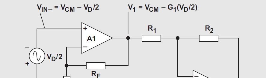
10 The first stage of the instrumentation amplifier is a non-inverting follower configuration. This configuration offer an extermelylarge input impedance. I D 1 IN+ IN IN+ R G I + I D IN D R F R DG D 1 CM 1 CM + G 1 Where G1 is the gain of the first stage G 1 R 1+ R We can notice that first stage amplifies only differential signal while common mode signal transfer unchanged at the output. F G F R D G

11 Extending the common mode voltage range When using instrumentation amplifier, it is necessary to take care about the value of the common-mode component of the input signal. Namely, at a certain value of CM the input op-amps reached the saturation. Both input operational amplifiers, A1 and A are in non-saturated mode when the following condition is satisfied: 1, CM + G1 D The range of the common mode voltage can be increased by decreasing thegainoftheinputstageg1: 1, ' const. D G1 D CM + CM + G sat ' 1 ' CM > CM ' 1 G1 G <


12 Extending the common mode voltage range IfordertoreducethegainofthefirststageG1andpreservethetotalgain Gtot,itisnecessarytoincreasethegainofthesecondstageG. When we reduce input voltage gain from G1 to a smaller gain of G1 the gain of the second stage should be changed from unity gain to: G ' G TOT ' G 1 ' ' R G R 1 Two feedback resistances of the differential amplifier R are usually realized as a serial connection of an internal resistance R and an external resistance Rext. This solution is not suitable for larger gain because in that case external resistors Rext, significantly increase the level of noise.

13 Extending the common mode voltage range Thecommonmodevoltagerangecanbeexpandedbyusingabuffered voltage divider in a feedback path form the output of A3 to its inverting input. In this case the output voltage is determined as: R R R1 R 3 This solution provides a wide range of gain with moderate resistor values ofr3andr4.furthermore,itpreservesahighvalueofcmrrasopposed to the previous solution with external resistors. 4
14 Rejection of the differential DC signal The signal conditioning in some applications is a challenge task due to the presence of a large differential DC signal and very small AC signal. In medical equipment such as EKG and EEG monitors, signal is sensed by electrodes on the skin surface. These electrodes typically generate a common-mode voltage of 1.5. The differential component of the signal is composed of DC voltage of about ±500 m and AC voltage between 0.5m and 1.5 m. The use of an active filter in front of an instrumentation amplifier is not a good solution because it decreases CMRR. The detection of small AC signal in the presence of large differential DC potential is performed in three steps: 1. Reduction of the input stage gain G1 in order to avoid saturation of the input operational amplifiers A1 i A.. Apply low-pass filtering in the output stage to remove the differential DC signal. 3. Apply high gain in the output stage to increase the level of the AC signal.

15 Rejection of the differential DC signal One way to reject DC differential signal is to add a buffered voltage divider and a low pas filter in the output stage of the instrumentation amplifier. The voltage divider feedbacks signal from the output to the inverting input anditspurposeistoenlargethegainoftheoutputstage. Thelowpassfilterreturnsignalfromtheoutputtothenon-invertinginput anditisusedtorejectdcdifferentialsignal.

16 oltagesattheop-ampinputscanbeexpressedas: After equating potentials at the inputs of the op-amp A3, we get the expression for the voltage gain: Rejection of the differential DC signal R R R n int int 0 1 C R j p ω ' 0 f 0 f j Where: + ' f f j f G A n 3 1 R R 4 G + int int ' 0 1 G C R f π

17 Rejection of the differential DC signal The alternative solution to reject differential DC signal is take the second stage gain of G1 and to introduce a separate gain stage. This gain stage contains an integrator and an inverting amplifier. The integrator composed of A5, Rint and Cint performs low-pass filtering. The final gain stage composed of op-amp A4 introduces additional gain and performs low-pass filtering of high-frequency noise.
18 Day 4 Problem 1 Design an electrocardiograph (ECG) amplifier by using an instrumentation amplifier with three rail-to-rail op-amps whose voltagesupplyis±5.theamplifiershouldbeabletoamplifythe following signal: common-mode voltage of 1.5, DC differential voltage of 0.4, AC differential voltage of 1m. Lower 3-dB frequency should be 0.05 Hz.
Introduction to Analog Interfacing. ECE/CS 5780/6780: Embedded System Design. Various Op Amps. Ideal Op Amps
 Introduction to Analog Interfacing ECE/CS 5780/6780: Embedded System Design Scott R. Little Lecture 19: Operational Amplifiers Most embedded systems include components that measure and/or control real-world
Concepts to be Reviewed
 Introductory Medical Device Prototyping Analog Circuits Part 3 Operational Amplifiers, http://saliterman.umn.edu/ Department of Biomedical Engineering, University of Minnesota Concepts to be Reviewed Operational
Differential Amplifier : input. resistance. Differential amplifiers are widely used in engineering instrumentation
 Differential Amplifier : input resistance Differential amplifiers are widely used in engineering instrumentation Differential Amplifier : input resistance v 2 v 1 ir 1 ir 1 2iR 1 R in v 2 i v 1 2R 1 Differential
Single Supply, MicroPower INSTRUMENTATION AMPLIFIER
 Single Supply, MicroPower INSTRUMENTATION AMPLIFIER FEATURES LOW QUIESCENT CURRENT: µa WIDE POWER SUPPLY RANGE Single Supply:. to Dual Supply:.9/. to ± COMMON-MODE RANGE TO (). RAIL-TO-RAIL OUTPUT SWING
Special-Purpose Operational Amplifier Circuits
 Special-Purpose Operational Amplifier Circuits Instrumentation Amplifier An instrumentation amplifier (IA) is a differential voltagegain device that amplifies the difference between the voltages existing
Analog Circuits Part 3 Operational Amplifiers
 Introductory Medical Device Prototyping Analog Circuits Part 3 Operational Amplifiers, http://saliterman.umn.edu/ Department of Biomedical Engineering, University of Minnesota Concepts to be Reviewed Operational
TRANSDUCER INTERFACE APPLICATIONS
 TRANSDUCER INTERFACE APPLICATIONS Instrumentation amplifiers have long been used as preamplifiers in transducer applications. High quality transducers typically provide a highly linear output, but at a
UNIT I. Operational Amplifiers
 UNIT I Operational Amplifiers Operational Amplifier: The operational amplifier is a direct-coupled high gain amplifier. It is a versatile multi-terminal device that can be used to amplify dc as well as
EKT 314 ELECTRONIC INSTRUMENTATION
 EKT 314 ELECTRONIC INSTRUMENTATION Elektronik Instrumentasi Semester 2 2012/2013 Chapter 3 Analog Signal Conditioning Session 2 Mr. Fazrul Faiz Zakaria school of computer and communication engineering.
Micropower, Single-Supply, Rail-to-Rail, Precision Instrumentation Amplifiers MAX4194 MAX4197
 General Description The is a variable-gain precision instrumentation amplifier that combines Rail-to-Rail single-supply operation, outstanding precision specifications, and a high gain bandwidth. This
Lecture Notes Unit-III
 Lecture Notes Unit-III FAQs Q1: An operational amplifier has a differential gain of 103 and CMRR of 100, input voltages are 120µV and 80µV, determine output voltage. 2 MARKS
Operational Amplifier BME 360 Lecture Notes Ying Sun
 Operational Amplifier BME 360 Lecture Notes Ying Sun Characteristics of Op-Amp An operational amplifier (op-amp) is an analog integrated circuit that consists of several stages of transistor amplification
Operational Amplifiers
 Operational Amplifiers Table of contents 1. Design 1.1. The Differential Amplifier 1.2. Level Shifter 1.3. Power Amplifier 2. Characteristics 3. The Opamp without NFB 4. Linear Amplifiers 4.1. The Non-Inverting
CHAPTER 3. Instrumentation Amplifier (IA) Background. 3.1 Introduction. 3.2 Instrumentation Amplifier Architecture and Configurations
 Background. 3.1 Introduction. 3.2 Instrumentation Amplifier Architecture and Configurations") CHAPTER 3 Instrumentation Amplifier (IA) Background 3.1 Introduction The IAs are key circuits in many sensor readout systems where, there is a need to amplify small differential signals in the presence
CHAPTER 3 Instrumentation Amplifier (IA) Background 3.1 Introduction The IAs are key circuits in many sensor readout systems where, there is a need to amplify small differential signals in the presence
Lesson number one. Operational Amplifier Basics
 What About Lesson number one Operational Amplifier Basics As well as resistors and capacitors, Operational Amplifiers, or Op-amps as they are more commonly called, are one of the basic building blocks
Analog Electronics. Lecture Pearson Education. Upper Saddle River, NJ, All rights reserved.
 Analog Electronics V Lecture 5 V Operational Amplifers Op-amp is an electronic device that amplify the difference of voltage at its two inputs. V V 8 1 DIP 8 1 DIP 20 SMT 1 8 1 SMT Operational Amplifers
Interface Electronic Circuits
 Lecture (5) Interface Electronic Circuits Part: 1 Prof. Kasim M. Al-Aubidy Philadelphia University-Jordan AMSS-MSc Prof. Kasim Al-Aubidy 1 Interface Circuits: An interface circuit is a signal conditioning
Chapter 10: The Operational Amplifiers
 Chapter 10: The Operational Amplifiers Electronic Devices Operational Amplifiers (op-amp) Op-amp is an electronic device that amplify the difference of voltage at its two inputs. It has two input terminals,
ELC224 Final Review (12/10/2009) Name:
 Name:") ELC224 Final Review (12/10/2009) Name: Select the correct answer to the problems 1 through 20. 1. A common-emitter amplifier that uses direct coupling is an example of a dc amplifier. 2. The frequency
ELC224 Final Review (12/10/2009) Name: Select the correct answer to the problems 1 through 20. 1. A common-emitter amplifier that uses direct coupling is an example of a dc amplifier. 2. The frequency
Precision INSTRUMENTATION AMPLIFIER
 Precision INSTRUMENTATION AMPLIFIER FEATURES LOW OFFSET VOLTAGE: µv max LOW DRIFT:.µV/ C max LOW INPUT BIAS CURRENT: na max HIGH COMMON-MODE REJECTION: db min INPUT OVER-VOLTAGE PROTECTION: ±V WIDE SUPPLY
ES250: Electrical Science. HW6: The Operational Amplifier
 ES250: Electrical Science HW6: The Operational Amplifier Introduction This chapter introduces the operational amplifier or op amp We will learn how to analyze and design circuits that contain op amps,
Homework Assignment 03
 Homework Assignment 03 Question 1 (Short Takes), 2 points each unless otherwise noted. 1. Two 0.68 μf capacitors are connected in series across a 10 khz sine wave signal source. The total capacitive reactance
Lecture 14 Interface Electronics (Part 2) ECE 5900/6900 Fundamentals of Sensor Design
 ECE 5900/6900 Fundamentals of Sensor Design") EE 4900: Fundamentals of Sensor Design 1 Lecture 14 Interface Electronics (Part 2) Interface Electronics (Part 2) 2 Linearizing Bridge Circuits (Sensor Tech Hand book) Precision Op amps, Auto Zero Op amps,
EE 4900: Fundamentals of Sensor Design 1 Lecture 14 Interface Electronics (Part 2) Interface Electronics (Part 2) 2 Linearizing Bridge Circuits (Sensor Tech Hand book) Precision Op amps, Auto Zero Op amps,
Dimensions in inches (mm) .021 (0.527).035 (0.889) .016 (.406).020 (.508 ) .280 (7.112).330 (8.382) Figure 1. Typical application circuit.
 .021 (0.527).035 (0.889) .016 (.406).020 (.508 ) .280 (7.112).330 (8.382) Figure 1. Typical application circuit.") IL Linear Optocoupler Dimensions in inches (mm) FEATURES Couples AC and DC signals.% Servo Linearity Wide Bandwidth, > khz High Gain Stability, ±.%/C Low Input-Output Capacitance Low Power Consumption,
IL Linear Optocoupler Dimensions in inches (mm) FEATURES Couples AC and DC signals.% Servo Linearity Wide Bandwidth, > khz High Gain Stability, ±.%/C Low Input-Output Capacitance Low Power Consumption,
Operational Amplifiers
 Operational Amplifiers From: http://ume.gatech.edu/mechatroni cs_course/opamp_f11.ppt What is an Op-Amp? The Surface An Operational Amplifier (Op-Amp) is an integrated circuit that uses external voltage
Low Cost, Low Power Instrumentation Amplifier AD620
 a FEATURES EASY TO USE Gain Set with One External Resistor (Gain Range to 000) Wide Power Supply Range (.3 V to V) Higher Performance than Three Op Amp IA Designs Available in -Lead DIP and SOIC Packaging
EE 3305 Lab I Revised July 18, 2003
 Operational Amplifiers Operational amplifiers are high-gain amplifiers with a similar general description typified by the most famous example, the LM741. The LM741 is used for many amplifier varieties
INA126. MicroPOWER INSTRUMENTATION AMPLIFIER Single and Dual Versions IN ) G V IN G = 5 +
 G V IN G = 5 +") INA6 INA6 INA6 INA6 INA6 INA6 INA6 SBOS06A JANUARY 996 REVISED AUGUST 005 MicroPOWER INSTRUMENTATION AMPLIFIER Single and Dual Versions FEATURES LOW QUIESCENT CURRENT: 75µA/chan. WIDE SUPPLY RANGE: ±.35V
INA6 INA6 INA6 INA6 INA6 INA6 INA6 SBOS06A JANUARY 996 REVISED AUGUST 005 MicroPOWER INSTRUMENTATION AMPLIFIER Single and Dual Versions FEATURES LOW QUIESCENT CURRENT: 75µA/chan. WIDE SUPPLY RANGE: ±.35V
High Speed FET-Input INSTRUMENTATION AMPLIFIER
 High Speed FET-Input INSTRUMENTATION AMPLIFIER FEATURES FET INPUT: I B = 2pA max HIGH SPEED: T S = 4µs (G =,.%) LOW OFFSET VOLTAGE: µv max LOW OFFSET VOLTAGE DRIFT: µv/ C max HIGH COMMON-MODE REJECTION:
2.996/6.971 Biomedical Devices Design Laboratory Lecture 7: OpAmps
 2.996/6.971 Biomedical Devices Design Laboratory Lecture 7: OpAmps Instructor: Dr. Hong Ma Oct. 3, 2007 Fundamental Circuit: Source and Load Sources Power supply Signal Generator Sensor Amplifier output
Examining a New In-Amp Architecture for Communication Satellites
 Examining a New In-Amp Architecture for Communication Satellites Introduction With more than 500 conventional sensors monitoring the condition and performance of various subsystems on a medium sized spacecraft,
Lecture #4 Basic Op-Amp Circuits
 Summer 2015 Ahmad El-Banna Faculty of Engineering Department of Electronics and Communications GEE336 Electronic Circuits II Lecture #4 Basic Op-Amp Circuits Instructor: Dr. Ahmad El-Banna Agenda Some
Chapter 10: Operational Amplifiers
 Chapter 10: Operational Amplifiers Differential Amplifier Differential amplifier has two identical transistors with two inputs and two outputs. 2 Differential Amplifier Differential amplifier has two identical
Operational Amplifier (Op-Amp)
") Operational Amplifier (Op-Amp) 1 Contents Op-Amp Characteristics Op-Amp Circuits - Noninverting Amplifier - Inverting Amplifier - Comparator - Differential - Summing - Integrator - Differentiator 2 Introduction
Operational Amplifier (Op-Amp) 1 Contents Op-Amp Characteristics Op-Amp Circuits - Noninverting Amplifier - Inverting Amplifier - Comparator - Differential - Summing - Integrator - Differentiator 2 Introduction
Voltage-to-Frequency and Frequency-to-Voltage Converter ADVFC32
 a FEATURES High Linearity 0.01% max at 10 khz FS 0.05% max at 100 khz FS 0.2% max at 500 khz FS Output TTL/CMOS Compatible V/F or F/V Conversion 6 Decade Dynamic Range Voltage or Current Input Reliable
Lecture #4 Special-purpose Op-amp Circuits
 Spring 2015 Benha University Faculty of Engineering at Shoubra ECE-322 Electronic Circuits (B) Lecture #4 Special-purpose Op-amp Circuits Instructor: Dr. Ahmad El-Banna Agenda Instrumentation Amplifiers
Operational Amplifiers
 Operational Amplifiers Spring 2008 Sean Lynch Lambros Samouris Tom Groshans History of Op Amps Non Named for their originally intended functions: performing mathematical operations and amplification Addition
ELEC207 LINEAR INTEGRATED CIRCUITS
 Concept of VIRTUAL SHORT For feedback amplifiers constructed with op-amps, the two op-amp terminals will always be approximately equal (V + = V - ) This condition in op-amp feedback amplifiers is known
Operational Amplifiers. Boylestad Chapter 10
 Operational Amplifiers Boylestad Chapter 10 DC-Offset Parameters Even when the input voltage is zero, an op-amp can have an output offset. The following can cause this offset: Input offset voltage Input
Dual FET-Input, Low Distortion OPERATIONAL AMPLIFIER
 www.burr-brown.com/databook/.html Dual FET-Input, Low Distortion OPERATIONAL AMPLIFIER FEATURES LOW DISTORTION:.3% at khz LOW NOISE: nv/ Hz HIGH SLEW RATE: 25V/µs WIDE GAIN-BANDWIDTH: MHz UNITY-GAIN STABLE
Low Noise, Low Distortion INSTRUMENTATION AMPLIFIER
 Low Noise, Low Distortion INSTRUMENTATION AMPLIFIER FEATURES LOW NOISE: nv/ Hz LOW THDN:.9% at khz, G = HIGH GBW: MHz at G = WIDE SUPPLY RANGE: ±9V to ±V HIGH CMRR: >db BUILT-IN GAIN SETTING RESISTORS:
Quad Picoampere Input Current Bipolar Op Amp AD704
 a FEATURES High DC Precision 75 V Max Offset Voltage V/ C Max Offset Voltage Drift 5 pa Max Input Bias Current.2 pa/ C Typical I B Drift Low Noise.5 V p-p Typical Noise,. Hz to Hz Low Power 6 A Max Supply
Single Supply, Rail to Rail Low Power FET-Input Op Amp AD820
 a FEATURES True Single Supply Operation Output Swings Rail-to-Rail Input Voltage Range Extends Below Ground Single Supply Capability from + V to + V Dual Supply Capability from. V to 8 V Excellent Load
Chapter 2. Operational Amplifiers
 Chapter 2. Operational Amplifiers Tong In Oh 1 2.3 The Noninverting Configuration v I is applied directly to the positive input terminal of the op amp One terminal of is connected to ground Closed-loop
Introduction to Op Amps
 Introduction to Op Amps ENGI 242 ELEC 222 Basic Op-Amp The op-amp is a differential amplifier with a very high open loop gain 25k AVOL 500k (much higher for FET inputs) high input impedance 500kΩ ZIN 10MΩ
Quad Picoampere Input Current Bipolar Op Amp AD704
 a FEATURES High DC Precision 75 V max Offset Voltage V/ C max Offset Voltage Drift 5 pa max Input Bias Current.2 pa/ C typical I B Drift Low Noise.5 V p-p typical Noise,. Hz to Hz Low Power 6 A max Supply
Low Cost Instrumentation Amplifier AD622
 a FEATURES Easy to Use Low Cost Solution Higher Performance than Two or Three Op Amp Design Unity Gain with No External Resistor Optional Gains with One External Resistor (Gain Range 2 to ) Wide Power
FET-Input, Low Power INSTRUMENTATION AMPLIFIER
 FET-Input, Low Power INSTRUMENTATION AMPLIFIER FEATURES LOW BIAS CURRENT: ±4pA LOW QUIESCENT CURRENT: ±4µA LOW INPUT OFFSET VOLTAGE: ±µv LOW INPUT OFFSET DRIFT: ±µv/ C LOW INPUT NOISE: nv/ Hz at f = khz
Model 176 and 178 DC Amplifiers
 Model 176 and 178 DC mplifiers Features*! Drifts to 100 MΩ! CMR: 120 db @! Gain Linearity of ±.005% *The key features of this amplifier series, listed above, do not necessarily apply
How to Monitor Sensor Health with Instrumentation Amplifiers
 White Paper How to Monitor Sensor Health with Instrumentation Amplifiers Introduction Many industrial and medical applications use instrumentation amplifiers (INAs) to condition small signals in the presence
Applied Electronics II
 Applied Electronics II Chapter 3: Operational Amplifier Part 1- Op Amp Basics School of Electrical and Computer Engineering Addis Ababa Institute of Technology Addis Ababa University Daniel D./Getachew
Lecture #2 Operational Amplifiers
 Spring 2015 Benha University Faculty of Engineering at Shoubra ECE-322 Electronic Circuits (B) Lecture #2 Operational Amplifiers Instructor: Dr. Ahmad El-Banna Agenda Introduction Op-Amps Input Modes and
Quad Picoampere Input Current Bipolar Op Amp AD704
 a FEATURES High DC Precision 75 V Max Offset Voltage V/ C Max Offset Voltage Drift 5 pa Max Input Bias Current.2 pa/ C Typical I B Drift Low Noise.5 V p-p Typical Noise,. Hz to Hz Low Power 6 A Max Supply
Single Supply, Rail to Rail Low Power FET-Input Op Amp AD820
 a FEATURES True Single Supply Operation Output Swings Rail-to-Rail Input Voltage Range Extends Below Ground Single Supply Capability from V to V Dual Supply Capability from. V to 8 V Excellent Load Drive
ECE-342 Test 1: Sep 27, :00-8:00, Closed Book. Name : SOLUTION
 ECE-342 Test 1: Sep 27, 2011 6:00-8:00, Closed Book Name : SOLUTION All solutions must provide units as appropriate. Use the physical constants and data as provided on the formula sheet the last page of
Low Drift, Low Power Instrumentation Amplifier AD621
 a FEATURES EASY TO USE Pin-Strappable Gains of and All Errors Specified for Total System Performance Higher Performance than Discrete In Amp Designs Available in 8-Lead DIP and SOIC Low Power,.3 ma Max
1) Consider the circuit shown in figure below. Compute the output waveform for an input of 5kHz
 Consider the circuit shown in figure below. Compute the output waveform for an input of 5kHz") ) Consider the circuit shown in figure below. Compute the output waveform for an input of 5kHz Solution: a) Input is of constant amplitude of 2 V from 0 to 0. ms and 2 V from 0. ms to 0.2 ms. The output
) Consider the circuit shown in figure below. Compute the output waveform for an input of 5kHz Solution: a) Input is of constant amplitude of 2 V from 0 to 0. ms and 2 V from 0. ms to 0.2 ms. The output
Homework Assignment 10
 Homework Assignment 10 Question The amplifier below has infinite input resistance, zero output resistance and an openloop gain. If, find the value of the feedback factor as well as so that the closed-loop
High Accuracy 8-Pin Instrumentation Amplifier AMP02
 a FEATURES Low Offset Voltage: 100 V max Low Drift: 2 V/ C max Wide Gain Range 1 to 10,000 High Common-Mode Rejection: 115 db min High Bandwidth (G = 1000): 200 khz typ Gain Equation Accuracy: 0.5% max
Dimensions in inches (mm) .268 (6.81).255 (6.48) .390 (9.91).379 (9.63) .045 (1.14).030 (.76) 4 Typ. Figure 1. Typical application circuit.
 .268 (6.81).255 (6.48) .390 (9.91).379 (9.63) .045 (1.14).030 (.76) 4 Typ. Figure 1. Typical application circuit.") LINEAR OPTOCOUPLER FEATURES Couples AC and DC signals.% Servo Linearity Wide Bandwidth, > KHz High Gain Stability, ±.%/C Low Input-Output Capacitance Low Power Consumption, < mw Isolation Test Voltage,
LINEAR OPTOCOUPLER FEATURES Couples AC and DC signals.% Servo Linearity Wide Bandwidth, > KHz High Gain Stability, ±.%/C Low Input-Output Capacitance Low Power Consumption, < mw Isolation Test Voltage,
350MHz, Ultra-Low-Noise Op Amps
 9-442; Rev ; /95 EVALUATION KIT AVAILABLE 35MHz, Ultra-Low-Noise Op Amps General Description The / op amps combine high-speed performance with ultra-low-noise performance. The is compensated for closed-loop
Linear IC s and applications
 Questions and Solutions PART-A Unit-1 INTRODUCTION TO OP-AMPS 1. Explain data acquisition system Jan13 DATA ACQUISITION SYSYTEM BLOCK DIAGRAM: Input stage Intermediate stage Level shifting stage Output
EE LINEAR INTEGRATED CIRCUITS & APPLICATIONS
 UNITII CHARACTERISTICS OF OPAMP 1. What is an opamp? List its functions. The opamp is a multi terminal device, which internally is quite complex. It is a direct coupled high gain amplifier consisting of
Unit WorkBook 1 Level 4 ENG U22 Electronic Circuits and Devices 2018 UniCourse Ltd. All Rights Reserved. Sample
 Pearson BTEC Level 4 Higher Nationals in Engineering (RQF) Unit 22: Electronic Circuits and Devices Unit Workbook 1 in a series of 4 for this unit Learning Outcome 1 Operational Amplifiers Page 1 of 23
Micropower, Single and Dual Supply Rail-to-Rail Instrumentation Amplifier AD627
 a FEATURES Micropower, 85 A Max Supply Current Wide Power Supply Range (+2.2 V to 8 V) Easy to Use Gain Set with One External Resistor Gain Range 5 (No Resistor) to, Higher Performance than Discrete Designs
Precision Gain=10 DIFFERENTIAL AMPLIFIER
 INA Precision Gain= DIFFERENTIAL AMPLIFIER FEATURES ACCURATE GAIN: ±.% max HIGH COMMON-MODE REJECTION: 8dB min NONLINEARITY:.% max EASY TO USE PLASTIC 8-PIN DIP, SO-8 SOIC PACKAGES APPLICATIONS G = DIFFERENTIAL
CLC1200 Instrumentation Amplifier
 CLC2 Instrumentation Amplifier General Description The CLC2 is a low power, general purpose instrumentation amplifier with a gain range of to,. The CLC2 is offered in 8-lead SOIC or DIP packages and requires
OPERATIONAL AMPLIFIER PREPARED BY, PROF. CHIRAG H. RAVAL ASSISTANT PROFESSOR NIRMA UNIVRSITY
 OPERATIONAL AMPLIFIER PREPARED BY, PROF. CHIRAG H. RAVAL ASSISTANT PROFESSOR NIRMA UNIVRSITY INTRODUCTION Op-Amp means Operational Amplifier. Operational stands for mathematical operation like addition,
Fast-Settling FET-Input INSTRUMENTATION AMPLIFIER
 INA Fast-Settling FET-Input INSTRUMENTATION AMPLIFIER FEATURES LOW BIAS CURRENT: pa max FAST SETTLING: 4µs to.% HIGH CMR: db min; db at khz INTERNAL GAINS:,,,, VERY LOW GAIN DRIFT: to ppm/ C LOW OFFSET
Chapter 9: Operational Amplifiers
 Chapter 9: Operational Amplifiers The Operational Amplifier (or op-amp) is the ideal, simple amplifier. It is an integrated circuit (IC). An IC contains many discrete components (resistors, capacitors,
Chapter 2. Operational Amplifiers
 Chapter 2. Operational Amplifiers Tong In Oh 1 2.5 Integrators and Differentiators Utilized resistors in the op-amp feedback and feed-in path Ideally independent of frequency Use of capacitors together
Example #6 1. An amplifier with a nominal gain
 1. An amplifier with a nominal gain A=1000 V/V exhibits a gain change of 10% as the operating temperature changes from 25 o C to 75 o C. If it is required to constrain the change to 0.1% by applying negative
DUAL ULTRA MICROPOWER RAIL-TO-RAIL CMOS OPERATIONAL AMPLIFIER
 ADVANCED LINEAR DEVICES, INC. ALD276A/ALD276B ALD276 DUAL ULTRA MICROPOWER RAILTORAIL CMOS OPERATIONAL AMPLIFIER GENERAL DESCRIPTION The ALD276 is a dual monolithic CMOS micropower high slewrate operational
Differential Amplifiers
 Differential Amplifiers Benefits of Differential Signal Processing The Benefits Become Apparent when Trying to get the Most Speed and/or Resolution out of a Design Avoid Grounding/Return Noise Problems
C H A P T E R 02. Operational Amplifiers
 C H A P T E R 02 Operational Amplifiers The Op-amp Figure 2.1 Circuit symbol for the op amp. Figure 2.2 The op amp shown connected to dc power supplies. The Ideal Op-amp 1. Infinite input impedance 2.
Op-Amp Simulation Part II
 Op-Amp Simulation Part II EE/CS 5720/6720 This assignment continues the simulation and characterization of a simple operational amplifier. Turn in a copy of this assignment with answers in the appropriate
Design and Simulation of Low Voltage Operational Amplifier
 Design and Simulation of Low Voltage Operational Amplifier Zach Nelson Department of Electrical Engineering, University of Nevada, Las Vegas 4505 S Maryland Pkwy, Las Vegas, NV 89154 United States of America
EXAM Amplifiers and Instrumentation (EE1C31)
") DELFT UNIVERSITY OF TECHNOLOGY Faculty of Electrical Engineering, Mathematics and Computer Science EXAM Amplifiers and Instrumentation (EE1C31) April 18, 2017, 9.00-12.00 hr This exam consists of four
DELFT UNIVERSITY OF TECHNOLOGY Faculty of Electrical Engineering, Mathematics and Computer Science EXAM Amplifiers and Instrumentation (EE1C31) April 18, 2017, 9.00-12.00 hr This exam consists of four
Lecture 4 Biopotential Amplifiers
 Bioinstrument Sahand University of Technology Lecture 4 Biopotential Amplifiers Dr. Shamekhi Summer 2016 OpAmp and Rules 1- A = (gain is infinity) 2- Vo = 0, when v1 = v2 (no offset voltage) 3- Rd = (input
Università degli Studi di Roma Tor Vergata Dipartimento di Ingegneria Elettronica. Analogue Electronics. Paolo Colantonio A.A.
 Università degli Studi di Roma Tor Vergata Dipartimento di Ingegneria Elettronica Analogue Electronics Paolo Colantonio A.A. 2056 Operational amplifiers (op amps) Operational amplifiers (op amps) are among
Homework Assignment 04
 Question 1 (Short Takes) Homework Assignment 04 1. Consider the single-supply op-amp amplifier shown. What is the purpose of R 3? (1 point) Answer: This compensates for the op-amp s input bias current.
Dual operational amplifier
 DESCRIPTION The 77 is a pair of high-performance monolithic operational amplifiers constructed on a single silicon chip. High common-mode voltage range and absence of latch-up make the 77 ideal for use
Emitter Coupled Differential Amplifier
 Emitter Coupled Differential Amplifier Returning to the transistor, a very common and useful circuit is the differential amplifier. It's basic circuit is: Vcc Q1 Q2 Re Vee To see how this circuit works,
Chapter 11 Operational Amplifiers and Applications
 Chapter Operational Amplifiers and Applications Chapter Goals Understand the magic of negatie feedback and the characteristics of ideal op amps. Understand the conditions for non-ideal op amp behaior so
Operational Amplifiers
 Operational Amplifiers Here we see two matched differential amps cascaded to form a basic OPAMP. The differential pair cancel temperature drifts and common mode noise at the input. First built to perform
Chapter 9: Operational Amplifiers
 Chapter 9: Operational Amplifiers The Operational Amplifier (or op-amp) is the ideal, simple amplifier. It is an integrated circuit (IC). An IC contains many discrete components (resistors, capacitors,
Examining a New In-Amp Architecture for Communication Satellites
 White Paper Examining a New In-Amp Architecture for Communication Satellites Introduction With more 500 conventional sensors monitoring the condition and performance of various subsystems on a medium sized
QUAD 5V RAIL-TO-RAIL PRECISION OPERATIONAL AMPLIFIER
 ADVANCED LINEAR DEVICES, INC. ALD472A/ALD472B ALD472 QUAD 5V RAILTORAIL PRECISION OPERATIONAL AMPLIFIER GENERAL DESCRIPTION The ALD472 is a quad monolithic precision CMOS railtorail operational amplifier
Signal Conditioning Systems
 Note-13 1 Signal Conditioning Systems 2 Generalized Measurement System: The output signal from a sensor has generally to be processed or conditioned to make it suitable for the next stage Signal conditioning
Practice questions for BIOEN 316 Quiz 4 Solutions for questions from 2011 and 2012 are posted with their respective quizzes.
 Practice questions for BIOEN 316 Quiz 4 Solutions for questions from 2011 and 2012 are posted with their respective quizzes. 1. [2011] When we talk about an ideal op-amp we usually make two assumptions.
New Rail-to-Rail Output Op Amps Bring Precision Performance to Low Voltage Systems
 New Rail-to-Rail Output Op Amps Bring Precision Performance to Low oltage Systems Introduction Linear Technology has recently released several new high precision op amps for use in low voltage systems.
Operational Amplifiers
 Operational Amplifiers for Basic Electronics http://cktse.eie.polyu.edu.hk/eie209 by Prof. Michael Tse January 2005 Where do we begin? We begin with assuming that the op-amp is an ideal element satisfying
Operational Amplifiers
 CHAPTER 5 Operational Amplifiers Operational amplifiers (or Op Amp) is an active circuit element that can perform mathematical operations between signals (e.g., amplify, sum, subtract, multiply, divide,
High Accuracy INSTRUMENTATION AMPLIFIER
 INA High Accuracy INSTRUMENTATION AMPLIFIER FEATURES LOW DRIFT:.µV/ C max LOW OFFSET VOLTAGE: µv max LOW NONLINEARITY:.% LOW NOISE: nv/ Hz HIGH CMR: db AT Hz HIGH INPUT IMPEDANCE: Ω -PIN PLASTIC, CERAMIC
Section 6 Chapter 2: Operational Amplifiers
 03 Section 6 Chapter : Operational Amplifiers eference : Microelectronic circuits Sedra sixth edition 4//03 4//03 Contents: - DC imperfections A. Offset voltage B. Solution of offset voltage C. Input bias
LT MHz, 30V/µs 16-Bit Accurate A V 2 Op Amp. Description. Features. Applications. Typical Application
 Features n Stable in Gain A (A = ) n MHz Gain Bandwidth Product n /μs Slew Rate n Settling Time: 8ns ( Step, ) n Specified at and Supplies n Low Distortion, 9.dB for khz, P-P n Maximum Input Offset oltage:
Dual Picoampere Input Current Bipolar Op Amp AD706
 a FEATURE HIGH DC PRECISION V max Offset Voltage.6 V/ C max Offset Drift pa max Input Bias Current LOW NOISE. V p-p Voltage Noise,. Hz to Hz LOW POWER A Supply Current Available in -Lead Plastic Mini-DlP,
Low Power INSTRUMENTATION AMPLIFIER
 INA2 ABRIDGED DATA SHEET For Complete Data Sheet Call Fax Line -800-8- Request Document Number 2 Low Power INSTRUMENTATION AMPLIFIER FEATURES LOW QUIESCENT CURRENT: 0µA max INTERNAL GAINS:,, 0, 00 LOW
Operational Amplifier as A Black Box
 Chapter 8 Operational Amplifier as A Black Box 8. General Considerations 8.2 Op-Amp-Based Circuits 8.3 Nonlinear Functions 8.4 Op-Amp Nonidealities 8.5 Design Examples Chapter Outline CH8 Operational Amplifier
IFB270 Advanced Electronic Circuits
 IFB270 Advanced Electronic Circuits Chapter 14: Special-purpose op-amp circuits Prof. Manar Mohaisen Department of EEC Engineering eview of the Precedent Lecture Introduce the level detection op-amp circuits