Test Report LP0002 ( ) Summit Data Communications Device Name: SDC-WB40NBT Brand: Summit Data Communications Model: SDC-WB40NBT
|
|
|
- Howard Jeremy Short
- 5 years ago
- Views:
Transcription

1 Test Report LP0002 ( ) Summit Data Communications Device Name: SDC-WB40NBT Brand: Summit Data Communications Model: SDC-WB40NBT GRANTEE: TEST SITE: Summit Data Communications 526 South Main St. Suite 805 Akron, OH Elliott Laboratories Boyce Road Fremont, CA REPORT DATE: March 14, 2012 FINAL TEST DATE: October 19, 20 and 21 and November 19 and 24, 2010 and May 11, August 2, 4, 10, 12, 13, 16, 17, 18 19, 20, 23, 24, 26 and October 6, 7, 19, 20 and 26 and November 3, 4, 7, 8, 9, 15, 2011 PRODUCT RECEIVED DATE: October 19, 2010 TOTAL NUMBER OF PAGES: 229 PROGRAM MGR / QUALITY ASSURANCE DELEGATE / TECHNICAL REVIEWER: FINAL REPORT PREPARER: Mark E Hill Staff Engineer David Guidotti Senior Technical Writer Elliott Laboratories is accredited by the A2LA, certificate number , to perform the test(s) listed in this report, except where noted otherwise. This report and the information contained herein represent the results of testing test articles identified and selected by the client performed to specifications and/or procedures selected by the client. National Technical Systems (NTS) makes no representations, expressed or implied, that such testing is adequate (or inadequate) to demonstrate efficiency, performance, reliability, or any other characteristic of the articles being tested, or similar products. This report should not be relied upon as an endorsement or certification by NTS of the equipment tested, nor does it represent any statement whatsoever as to its merchantability or fitness of the test article, or similar products, for a particular purpose. This report shall not be reproduced except in full File R85917 Page 1 of 229
2 Elliott Laboratories -- EMC Department REVISION HISTORY Test Report Report Date: March 14, 2012 Rev# Date Comments Modified By First release File R85917 Page 2 of 229
3 Elliott Laboratories -- EMC Department TABLE OF CONTENTS Test Report Report Date: March 14, 2012 TITLE PAGE... 1 REVISION HISTORY... 2 TABLE OF CONTENTS... 3 SCOPE... 4 OBJECTIVE... 4 SUMMARY OF RESULTS... 5 GENERAL REQUIREMENTS APPLICABLE TO ALL BANDS... 5 GENERAL TECHNICAL REQUIREMENTS... 5 DIGITAL TRANSMISSION SYSTEMS ( MHz)... 6 DIGITAL TRANSMISSION SYSTEMS ( MHz)... 7 UNII DEVICES, SECTION MEASUREMENT UNCERTAINTIES DEVIATIONS FROM THE STANDARD EQUIPMENT UNDER TEST (EUT) DETAILS GENERAL OTHER EUT DETAILS ANTENNA SYSTEM ENCLOSURE MODIFICATIONS SUPPORT EQUIPMENT EUT INTERFACE PORTS EUT OPERATION TEST SITE GENERAL INFORMATION CONDUCTED EMISSIONS CONSIDERATIONS RADIATED EMISSIONS CONSIDERATIONS MEASUREMENT INSTRUMENTATION RECEIVER SYSTEM INSTRUMENT CONTROL COMPUTER LINE IMPEDANCE STABILIZATION NETWORK (LISN) FILTERS/ATTENUATORS ANTENNAS ANTENNA MAST AND EQUIPMENT TURNTABLE INSTRUMENT CALIBRATION TEST PROCEDURES EUT AND CABLE PLACEMENT CONDUCTED EMISSIONS RADIATED EMISSIONS CONDUCTED EMISSIONS FROM ANTENNA PORT BANDWIDTH MEASUREMENTS SPECIFICATION LIMITS AND SAMPLE CALCULATIONS CONDUCTED EMISSIONS SPECIFICATION LIMITS: LP0002 SECTION GENERAL RADIATED EMISSIONS SPECIFICATION LIMITS, LP0002 SECTION OUTPUT POWER LIMITS DIGITAL TRANSMISSION SYSTEMS (LP ) OUTPUT POWER LIMITS FHSS SYSTEMS (LP ) TRANSMITTER RADIATED SPURIOUS EMISSIONS LIMITS (LP ) OUTPUT POWER LIMITS FOR UNII DEVICES(LP ) SPURIOUS EMISSIONS LIMITS UNII DEVICES (LP ) SAMPLE CALCULATIONS - CONDUCTED EMISSIONS SAMPLE CALCULATIONS - RADIATED EMISSIONS SAMPLE CALCULATIONS - FIELD STRENGTH TO EIRP CONVERSION APPENDIX A TEST EQUIPMENT CALIBRATION DATA APPENDIX B TEST DATA LOG SHEETS APPENDIX C RADIATED EMISSIONS TEST CONFIGURATION PHOTOGRAPHS APPENDIX D DETAILED PHOTOGRAPHS OF CONSTRUCTION END OF REPORT File R85917 Page 3 of 229
4 Elliott Laboratories -- EMC Department SCOPE Test Report Report Date: March 14, 2012 An electromagnetic emissions test has been performed on the Summit Data Communications model SDC-WB40NBT pursuant to LP0002 ( ) - Technical Regulations for Low-power Radio-frequency Devices. Conducted and radiated emissions data has been collected, reduced, and analyzed within this report in accordance with measurement guidelines set forth in ANSI C63.4:2003 and LP0002 as outlined in Elliott Laboratories test procedures. The intentional radiator above has been tested in a simulated typical installation to demonstrate compliance with the relevant performance and procedural standards. Final system data was gathered in a mode that tended to maximize emissions by varying orientation of EUT, orientation of power and I/O cabling, antenna search height, and antenna polarization. Every practical effort was made to perform an impartial test using appropriate test equipment of known calibration. All pertinent factors have been applied to reach the determination of compliance. The test results recorded herein are based on a single type test of the Summit Data Communications model SDC-WB40NBT and therefore apply only to the tested sample. The sample was selected and prepared by Ron Seide of Summit Data Communications OBJECTIVE The primary objective of the manufacturer is compliance with LP0002 ( ) - Technical Regulations for Low-power Radio-frequency Devices for the radiated and conducted emissions of intentional radiators. Certification is a procedure where the manufacturer or a contracted laboratory makes measurements and submits the test data and technical information for device approvals. Once the equipment authorization has been obtained, the label indicating compliance must be attached to all identical units that are subsequently manufactured. File R85917 Page 4 of 229
5 Elliott Laboratories -- EMC Department SUMMARY OF RESULTS GENERAL REQUIREMENTS APPLICABLE TO ALL BANDS LP0002 Section 2.10 (1) 2.10 (2) 2.10 (3) 2.10 (4) Description Users/Operational Manual Users/Operational Manual Users/Operational Manual Users/Operational Manual 5.12 Channel Selection Measured Value / Comments Device was tested on the top, bottom and center channels in each band Limit / Requirement Control, adjust, on/off operation will not cause violation Warnings against adjustments of the device Warnings against any replacement of components Full Contents of Article Measurements on three channels in each band Test Report Report Date: March 14, 2012 Result (margin) Complies Complies Complies Complies N/A GENERAL TECHNICAL REQUIREMENTS LP0002 Section 2.3 Description Measured Value Comments Refer to: Result AC Conducted Emissions 0.457MHz (-14.1dB) (4) Antenna Gain See EUT description (4) RF Connector 5.20 RF Exposure Requirements (minimum 20 cm separation) Module uses u.fl connectors AC conducted emissions shall meet the emissions limits detailed in 2.3 Antenna gains in excess of 6dBi may require reduction in output power, see appropriate rule part Complies - Complies - - Complies mw/cm 2 MPE shall be less than 1 mw/cm 2 Complies DTS Operation: b: 12.8MHz g: 16.7MHz 2.4GHz, n20: 17.9MHz - 99% bandwidth a: 16.9MHz 5GHz, n20: 18.2MHz UNII Operation: a: 17.3MHz n20: 18.1MHz Information only File R85917 Page 5 of 229
6 Elliott Laboratories -- EMC Department DIGITAL TRANSMISSION SYSTEMS ( MHz) LP0002 Section Test Report Report Date: March 14, 2012 Description Measured Value Comments Refer to: Result b: 15.2dBm (0.033 Watts) (2.3) Output Power, MHz g: 12.6dBm (0.018 Watts) n20: 9.5dBm (0.009W) Maximum power is 1Watt, reduced by the amount in db that the antenna gain exceeds 6dBi Note 1 Complies (1) Digital Modulation EIRP = W Note 1 Systems uses OFDM / DSSS techniques b: -5.3dBm/3kHz System must utilize a digital transmission technology Complies (6.2.2) Power Spectral Density g: -11.8dBm/3kHz Maximum permitted is 8dBm/3kHz Complies (6.2.1) 6dB Bandwidth n20: -14.4dBm/3kHz b: 9.0MHz g: 15.1MHz n20: 15.1MHz Minimum allowed is 500kHz Complies (5) Antenna Port Spurious Emissions 30MHz 25 GHz All spurious All spurious emissions < - emissions < -20dBc or < -30dBc Note 2 20dBc. Complies (5) & 2.8 Radiated Spurious Emissions 30MHz 25GHz MHz (-0.1dB) Section 2.8 in restricted bands, all others below -20dBc / -30dBc (Note 2) Complies 2.11 Radiated Spurious Emissions 30MHz 25 GHz MHz (-5.0dB) Receive mode emissions shall meet the emissions limits detailed in 2.8 Complies Note 1: Maximum antenna gain is 3.0, which is below 6dBi therefore the limit is 1 Watt (30dBm). Note 2: For those modes that were tested using a peak power meter, a limit of -20dBc was used. For those modes that were tested using the averaging method described in LP (2.3), a limit of -30dBc was used. Refer to the test data in the appendix for details File R85917 Page 6 of 229
7 Elliott Laboratories -- EMC Department DIGITAL TRANSMISSION SYSTEMS ( MHz) LP0002 Section (2.3) (1) (6.2.2) (6.2.1) Test Report Report Date: March 14, 2012 Description Measured Value Comments Refer to: Result Output Power (multipoint systems) Digital Modulation Power Spectral Density 6dB Bandwidth a: 7.9dBm (0.006 Watts) n20: 10.6dBm (0.012 Watts) EIRP = W Note 1 Systems uses OFDM / DSSS techniques a: -11.8dBm/3kHz n20: -10.2dBm/3kHz a: 15.0MHz n20: 16.8MHz Maximum power is 1Watt, reduced by the amount in db that the antenna gain exceeds 6dBi Note 1 System must utilize a digital transmission technology Maximum permitted is 8dBm/3kHz Minimum allowed is 500kHz Complies Complies Complies Complies (5) Antenna Port Spurious Emissions 30MHz 25 GHz All spurious All spurious emissions < - emissions < -20dBc or < -30dBc Note 2 20dBc. Complies (5) & 2.8 Radiated Spurious Emissions 30MHz 25GHz MHz (-0.2dB) Section 2.8 in restricted bands, all others below -20dBc / -30dBc (Note 2) Complies 2.11 Radiated Spurious Emissions 30MHz 25 GHz MHz (-5.0dB) Receive mode emissions shall meet the emissions limits detailed in 2.8 Complies Note 1: Maximum antenna gain is 6.5dBi, which exceeds 6dBi therefore the limit is 0.89 Watt (29.5dBm). Note 2: For those modes that were tested using a peak power meter, a limit of -20dBc was used. For those modes that were tested using the averaging method described in LP (2.3), a limit of -30dBc was used. Refer to the test data in the appendix for details. File R85917 Page 7 of 229
8 Elliott Laboratories -- EMC Department UNII DEVICES, SECTION 4.7 LP0002 Section Requirements Specific To Operation in the GHz Band Test Report Report Date: March 14, 2012 Description Measured Value Comments Refer to: Result Indoor Use (1) 26dB Bandwidth 22.2MHz 4.7.2(1) Output Power Power Spectral Density a: 14.2dBm (0.026W) n20: 13.2dBm (0.021W) (Max eirp: 0.118W) a: 3.1dBm/MHz Device restricted to indoor use in this band N/A limits output power if < 20MHz 17 dbm / 50mW (eirp < 30dBm) Complies N/A Complies 4.7.2(1) n20: 4.0 dbm/mhz Complies 1.7dBm/MHz Note 1: Maximum antenna gain is 6.5dBi therefore the limit is 44.7mW (16.5dBm). LP0002 Section 4.7.2(2) Requirements Specific To Operation in the GHz Band Description Measured Value Comments Refer to: Result 26dB Bandwidth 4.7.2(2) Output Power 22.3MHz a: 15.0dBm (0.031W) n20: 13.2dBm (0.021W) N/A limits output power if < 20MHz 23.5 dbm / 223.9mW (eirp < 30dBm) N/A Complies (Max eirp: 0.140W) a: 4.7.2(2) Power Spectral 4.0 dbm/mhz Density n20: 11 dbm/mhz Complies 2.1dBm/MHz dB bandwidth of all GHz Applies to Master devices channels falls outside Slave use only only the band. N/A Note 1: Maximum antenna gain is 6.5dBi therefore the limit is 44.7mW (16.5dBm). File R85917 Page 8 of 229
9 Elliott Laboratories -- EMC Department Test Report Report Date: March 14, 2012 LP0002 Section (1) Modulation 4.7.3(4)/ / (6) (2.1) (2.2) 4.7.4(1) Requirements for All U-NII Devices Description Measured Value Comments Refer to: Result Spurious Emissions below 1GHz Spurious Emissions above 1GHz Peak Excursion Ratio Frequency Stability Transmit Power Control Radiated Spurious Emissions 30MHz 25 GHz Dynamic frequency Selection (device without radar detection) Operation in the absence of information to transmit OFDM modulation is used No emissions below 1 GHz related to the transmitter were detected MHz (-0.2dB) Digital modulation is required Refer to Standard Refer to Standard - Complies Complies Complies 11.8 db < 13dB Complies Frequency stability is better than 10ppm (Operational Description) TPC is not required as the device operates at below 500mW eirp MHz (-2.2dB) Refer to separate test report, reference R86361 Operation is discontinued in the absence of information Refer to Standard The U-NII device shall have the capability to operate with a mean EIRP value lower than 24dBm (250mW) Receive mode emissions shall meet the emissions limits detailed in 2.8 Channel move time < 10s Channel closing transmission time < 260ms Device shall automatically discontinue operation in the absence of information to transmit Complies Complies Complies Complies Complies File R85917 Page 9 of 229
10 Elliott Laboratories -- EMC Department MEASUREMENT UNCERTAINTIES Test Report Report Date: March 14, 2012 ISO/IEC requires that an estimate of the measurement uncertainties associated with the emissions test results be included in the report. The measurement uncertainties given below are based on a 95% confidence level and were calculated in accordance with UKAS document LAB 34. Measurement Type RF power, conducted (power meter) RF power, conducted (Spectrum analyzer) Conducted emission of transmitter Conducted emission of receiver Radiated emission (substitution method) Radiated emission (field strength) Conducted Emissions (AC Power) Measurement Unit Frequency Range Expanded Uncertainty dbm 25 to 7000 MHz ± 0.52 db dbm 25 to 7000 MHz ± 0.7 db dbm 25 to MHz ± 0.7 db dbm 25 to MHz ± 0.7 db dbm 25 to MHz ± 2.5 db dbμv/m 25 to 1000 MHz ± 3.6 db 1000 to MHz ± 6.0 db dbμv 0.15 to 30 MHz ± 2.4 db DEVIATIONS FROM THE STANDARD All measurements were made in accordance with the requirements of the LP0002 ( ) standard and ANSI C63.4 test methods and procedures. File R85917 Page 10 of 229
11 Elliott Laboratories -- EMC Department EQUIPMENT UNDER TEST (EUT) DETAILS GENERAL Test Report Report Date: March 14, 2012 The Summit Data Communications model SDC-WB40NBT is an abgn 1x1 with Bluetooth 2.1 module. The sample was received on October 19, 2010 and tested on October 19, 20 and 21 and November 19 and 24, 2010 and May 11, August 2, 4, 10, 12, 13, 16, 17, 18 19, 20, 23, 24, 26 and October 6, 7, 19, 20 and 26 and November 3, 4, 7, 8, 9, 15, The EUT consisted of the following component(s): Company Model Description Serial Number FCC ID SDC abgn 1x TWG- Summit WB40NBT with BT Prototype SDCWB40NBT OTHER EUT DETAILS The EUT supports single transmit chain operation. The EUT supports 20MHz operation only. ANTENNA SYSTEM Monopole Antenna and 5GHz bands - Huber+Suhner, SOA 2459/360/5/0/V_C, 3dBi (2.4GHz), 6.5dBi (5GHz) Dipole Antenna #1-2.4 and 5GHz bands - Larsen, R , 1.6dBi (2.4GHz), 5dBi (5GHz) Dipole Antenna #2-2.4 GHz only - Cisco Air-Ant dBi(2.4GHz) Magnetic Dipole - 2.4GHz and 5GHz bands Ethertronics, 2.5dBi (2.4GHz), 5dBi (5GHz) In the 2.4GHz range, the Huber+Suhner (H&S), Cisco and Ethertronics antennas were tested as they represented the highest gain antennas of each available type. In the 5GHz range, the H&S, Larsen, and Ethertronics antennas were tested as the represented the highest gain antennas of each available type. The antenna connects to the EUT via a non-standard u.fl antenna connector, thereby meeting the requirements of FCC ENCLOSURE The EUT has no enclosure. It is designed to be installed within the enclosure of a host computer. MODIFICATIONS No modifications were made to the EUT during the time the product was at Elliott. File R85917 Page 11 of 229
12 Elliott Laboratories -- EMC Department SUPPORT EQUIPMENT The following equipment was used as support equipment for testing: Test Report Report Date: March 14, 2012 Company Model Description Serial Number FCC ID Lenovo Inspiron 1545 Laptop Computer (Note 1) 953R2K1 DoC GME AC/DC Adapter GFP181U-A330 (Note 2) Battery Pack (Note 3) - - Note 1 - Used to configure the EUT and then disconnected prior to testing Note 2 Used for AC conducted emissions only Note 3 Used for radiated spurious emissions tests EUT INTERFACE PORTS The I/O cabling configuration during testing was as follows: Port AC/DC Adapter DC out Connected To Cable(s) Description Shielded or Unshielded Length(m) WB40 2wire Unshielded 1.5m Battery Pack WB40 2wire Unshielded 0.1m EUT OPERATION During testing, the EUT was configured to transmit continuously at the lowest data rate for the mode as this resulted in the highest output power. File R85917 Page 12 of 229
13 Elliott Laboratories -- EMC Department TEST SITE GENERAL INFORMATION Test Report Report Date: March 14, 2012 Final test measurements were taken at the test sites listed below. Pursuant to section of the FCC s Rules and section 3.3 of RSP-100, construction, calibration, and equipment data has been filed with the Commission and with Industry Canada. Site Registration Numbers FCC Canada Location Chamber B-3 Chamber B Boyce Road Chamber B-5 Fremont, Chamber 7 A2LA CA B-7 accreditation All test sites are covered under the A2LA accreditation and the lab code US0027 for measurements against LP0002. ANSI C63.4:2003 recommends that ambient noise at the test site be at least 6 db below the allowable limits. Ambient levels are below this requirement. The test site(s) contain separate areas for radiated and conducted emissions testing. Considerable engineering effort has been expended to ensure that the facilities conform to all pertinent requirements of ANSI C63.4:2003 and LP0002. CONDUCTED EMISSIONS CONSIDERATIONS Conducted emissions testing is performed in conformance with ANSI C63.4:2003 and LP0002. Measurements are made with the EUT connected to the public power network through a nominal, standardized RF impedance, which is provided by a line impedance stabilization network, known as a LISN. A LISN is inserted in series with each currentcarrying conductor in the EUT power cord. RADIATED EMISSIONS CONSIDERATIONS The FCC has determined that radiation measurements made in a shielded enclosure are not suitable for determining levels of radiated emissions. Radiated measurements are performed in an open field environment or in a semi-anechoic chamber. The test sites are maintained free of conductive objects within the CISPR defined elliptical area incorporated in ANSI C63.4:2003 guidelines and meet the Normalized Site Attenuation (NSA) requirements of ANSI C63.4:2003. File R85917 Page 13 of 229
14 Elliott Laboratories -- EMC Department MEASUREMENT INSTRUMENTATION RECEIVER SYSTEM Test Report Report Date: March 14, 2012 An EMI receiver as specified in CISPR is used for emissions measurements. The receivers used can measure over the frequency range of 9 khz up to 2000 MHz. These receivers allow both ease of measurement and high accuracy to be achieved. The receivers have Peak, Average, and CISPR (Quasi-peak) detectors built into their design so no external adapters are necessary. The receiver automatically sets the required bandwidth for the CISPR detector used during measurements. If the repetition frequency of the signal being measured is below 20Hz, peak measurements are made in lieu of Quasi-Peak measurements. For measurements above the frequency range of the receivers, a spectrum analyzer is utilized because it provides visibility of the entire spectrum along with the precision and versatility required to support engineering analysis. Average measurements above 1000MHz are performed on the spectrum analyzer using the linear-average method with a resolution bandwidth of 1 MHz and a video bandwidth of 10 Hz, unless the signal is pulsed in which case the average (or video) bandwidth of the measuring instrument is reduced to onset of pulse desensitization and then increased. INSTRUMENT CONTROL COMPUTER The receivers utilize either a Rohde & Schwarz EZM Spectrum Monitor/Controller or contain an internal Spectrum Monitor/Controller to view and convert the receiver measurements to the field strength at an antenna or voltage developed at the LISN measurement port, which is then compared directly with the appropriate specification limit. This provides faster, more accurate readings by performing the conversions described under Sample Calculations within the Test Procedures section of this report. Results are printed in a graphic and/or tabular format, as appropriate. A personal computer is used to record all measurements made with the receivers. The Spectrum Monitor provides a visual display of the signal being measured. In addition, the controller or a personal computer run automated data collection programs which control the receivers. This provides added accuracy since all site correction factors, such as cable loss and antenna factors are added automatically. LINE IMPEDANCE STABILIZATION NETWORK (LISN) Line conducted measurements utilize a fifty microhenry Line Impedance Stabilization Network as the monitoring point. The LISN used also contains a 250 uh CISPR adapter. This network provides for calibrated radio frequency noise measurements by the design of the internal low pass and high pass filters on the EUT and measurement ports, respectively. File R85917 Page 14 of 229
15 Elliott Laboratories -- EMC Department FILTERS/ATTENUATORS Test Report Report Date: March 14, 2012 External filters and precision attenuators are often connected between the receiving antenna or LISN and the receiver. This eliminates saturation effects and non-linear operation due to high amplitude transient events. ANTENNAS A loop antenna is used below 30 MHz. For the measurement range 30 MHz to 1000 MHz either a combination of a biconical antenna and a log periodic or a bi-log antenna is used. Above 1000 MHz, horn antennas are used. The antenna calibration factors to convert the received voltage to an electric field strength are included with appropriate cable loss and amplifier gain factors to determine an overall site factor, which is then programmed into the test receivers or incorporated into the test software. ANTENNA MAST AND EQUIPMENT TURNTABLE The antennas used to measure the radiated electric field strength are mounted on a nonconductive antenna mast equipped with a motor-drive to vary the antenna height. Measurements below 30 MHz are made with the loop antenna at a fixed height of 1m above the ground plane. ANSI C63.4:2003 specifies that the test height above ground for table mounted devices shall be 80 centimeters. Floor mounted equipment shall be placed on the ground plane if the device is normally used on a conductive floor or separated from the ground plane by insulating material from 3 to 12 mm if the device is normally used on a non-conductive floor. During radiated measurements, the EUT is positioned on a motorized turntable in conformance with this requirement. INSTRUMENT CALIBRATION All test equipment is regularly checked to ensure that performance is maintained in accordance with the manufacturer's specifications. All antennas are calibrated at regular intervals with respect to tuned half-wave dipoles. An exhibit of this report contains the list of test equipment used and calibration information. File R85917 Page 15 of 229
16 Elliott Laboratories -- EMC Department TEST PROCEDURES EUT AND CABLE PLACEMENT Test Report Report Date: March 14, 2012 The regulations require that interconnecting cables be connected to the available ports of the unit and that the placement of the unit and the attached cables simulate the worst case orientation that can be expected from a typical installation, so far as practicable. To this end, the position of the unit and associated cabling is varied within the guidelines of ANSI C63.4:2003, and the worst-case orientation is used for final measurements. CONDUCTED EMISSIONS Conducted emissions are measured at the plug end of the power cord supplied with the EUT. Excess power cord length is wrapped in a bundle between 30 and 40 centimeters in length near the center of the cord. Preliminary measurements are made to determine the highest amplitude emission relative to the specification limit for all the modes of operation. Placement of system components and varying of cable positions are performed in each mode. A final peak mode scan is then performed in the position and mode for which the highest emission was noted on all current carrying conductors of the power cord. LISN EUT LISN AE 0.4m 0.8m Figure 1 Typical Conducted Emissions Test Configuration File R85917 Page 16 of 229
17 Elliott Laboratories -- EMC Department RADIATED EMISSIONS Test Report Report Date: March 14, 2012 A preliminary scan of the radiated emissions is performed in which all significant EUT frequencies are identified with the system in a nominal configuration. At least two scans are performed, one scan for each antenna polarization (horizontal and vertical; loop parallel and perpendicular to the EUT). During the preliminary scans, the EUT is rotated through 360, the antenna height is varied (for measurements above 30 MHz) and cable positions are varied to determine the highest emission relative to the limit. Preliminary scans may be performed in a fully anechoic chamber for the purposes of identifying the frequencies of the highest emissions from the EUT. A speaker is provided in the receiver to aid in discriminating between EUT and ambient emissions. Other methods used during the preliminary scan for EUT emissions involve scanning with near field magnetic loops, monitoring I/O cables with RF current clamps, and cycling power to the EUT. Final maximization is a phase in which the highest amplitude emissions identified in the spectral search are viewed while the EUT azimuth angle is varied from 0 to 360 degrees relative to the receiving antenna. The azimuth, which results in the highest emission is then maintained while varying the antenna height from one to four meters (for measurements above 30 MHz, measurements below 30 MHz are made with the loop antenna at a fixed height of 1m). The result is the identification of the highest amplitude for each of the highest peaks. Each recorded level is corrected in the receiver using appropriate factors for cables, connectors, antennas, and preamplifier gain. When testing above 18 GHz, the receive antenna is located at 1meter from the EUT and the antenna height is restricted to a maximum of 2.5 meters. REAR VIEW 0.4m AC Outlets (flush-mounted) 0.8m SIDE VIEW Typical Test Configuration for Radiated Field Strength Measurements File R85917 Page 17 of 229
18 Elliott Laboratories -- EMC Department Test Report Report Date: March 14, 2012 Antenna EUT d The ground plane extends beyond the ellipse defined in CISPR 16 / CISPR 22 / ANSI C63.4 and is large enough to accommodate test distances (d) of 3m and 10m. Refer to the test data tables for the actual measurement distance. EUT d Antenna height range 1 to 4 m 0.8m Test Configuration for Radiated Field Strength Measurements OATS- Plan and Side Views File R85917 Page 18 of 229
19 Elliott Laboratories -- EMC Department Test Report Report Date: March 14, 2012 EUT d Antenna The anechoic materials on the walls and ceiling ensure compliance with the normalized site attenuation requirements of CISPR 16 / CISPR 22 / ANSI C63.4 for an alternate test site at the measurement distances used. Floor-standing equipment is placed on the floor with insulating supports between the unit and the ground plane. EUT d 0.8m Antenna height range 1 to 4 m Test Configuration for Radiated Field Strength Measurements Semi-Anechoic Chamber, Plan and Side Views File R85917 Page 19 of 229
20 Elliott Laboratories -- EMC Department CONDUCTED EMISSIONS FROM ANTENNA PORT Test Report Report Date: March 14, 2012 Direct measurements of power, bandwidth and power spectral density are performed, where possible, with the antenna port of the EUT connected to either the power meter or spectrum analyzer via a suitable attenuator and/or filter. These are used to ensure that the front end of the measurement instrument is not overloaded by the fundamental transmission. EUT Attenuator (optional) Spectrum Analyzer (or Power Meter) Test Configuration for Antenna Port Measurements Measurement bandwidths (video and resolution) are set in accordance with the relevant standards and Elliott s test procedures for the type of radio being tested. When power measurements are made using a resolution bandwidth less than the signal bandwidth the power is calculated by summing the power across the signal bandwidth using either the analyzer channel power function or by capturing the trace data and calculating the power using software. In both cases the summed power is corrected to account for the equivalent noise bandwidth (ENBW) of the resolution bandwidth used. If power averaging is used (typically for certain digital modulation techniques), the EUT is configured to transmit continuously. Power averaging is performed using either the built-in function of the analyzer or, if the analyzer does not feature power averaging, using external software. In both cases the average power is calculated over a number of sweeps (typically 100). When the EUT cannot be configured to continuously transmit then either the analyzer is configured to perform a gated sweep to ensure that the power is averaged over periods that the device is transmitting or power averaging is disabled and a max-hold feature is used. If a power meter is used to make output power measurements the sensor head type (peak or average) is stated in the test data table. BANDWIDTH MEASUREMENTS The 6dB, 20dB and/or 26dB signal bandwidth is measured in using the bandwidths recommended by ANSI C63.4 and LP0002. When required, the 99% bandwidth is measured using the methods detailed in RSS GEN. File R85917 Page 20 of 229
21 Elliott Laboratories -- EMC Department SPECIFICATION LIMITS AND SAMPLE CALCULATIONS Test Report Report Date: March 14, 2012 The limits for conducted emissions are given in units of microvolts, and the limits for radiated emissions are given in units of microvolts per meter at a specified test distance. Data is measured in the logarithmic form of decibels relative to one microvolt, or db microvolts (dbuv). For radiated emissions, the measured data is converted to the field strength at the antenna in db microvolts per meter (dbuv/m). The results are then converted to the linear forms of uv and uv/m for comparison to published specifications. For reference, converting the specification limits from linear to decibel form is accomplished by taking the base ten logarithm, then multiplying by 20. These limits in both linear and logarithmic form are as follows: CONDUCTED EMISSIONS SPECIFICATION LIMITS: LP0002 SECTION 2.3 The table below shows the limits for the emissions on the AC power line from an intentional radiator and a receiver. Frequency (MHz) to Average Limit (dbuv) Linear decrease on logarithmic frequency axis between 56.0 and 46.0 Quasi Peak Limit (dbuv) Linear decrease on logarithmic frequency axis between 66.0 and to to File R85917 Page 21 of 229
22 Elliott Laboratories -- EMC Department GENERAL RADIATED EMISSIONS SPECIFICATION LIMITS, LP0002 SECTION 2.8 Test Report Report Date: March 14, 2012 The table below shows the limits for the spurious emissions from transmitters that fall in restricted bands 1, the limits for all emissions from a low power device operating under the general rules of LP0002 and the limits for receiver spurious emissions. Note that receivers operating below 30 MHz are exempt from these requirements and receiver spurious limits do not apply below 30MHz. Frequency Range (MHz) Limit (uv/m) Limit 3m) /F 300m *log 10 (F KHz 300m /F 30m *log 10 (F KHz 30m to 30 30m 30m 30 to 88 3m 3m 88 to 216 3m 3m 216 to 960 3m 3m Above 960 3m 3m OUTPUT POWER LIMITS DIGITAL TRANSMISSION SYSTEMS (LP ) The table below shows the limits for output power and output power density. Where the signal bandwidth is less than 20 MHz the maximum output power is reduced to the power spectral density limit plus 10 times the log of the bandwidth (in MHz). Operating Frequency (MHz) Output Power Power Spectral Density Watt (30 dbm) 8 dbm/3khz Watt (30 dbm) 8 dbm/3khz Watt (30 dbm) 8 dbm/3khz The maximum permitted output power is reduced by 1dB for every db the antenna gain exceeds 6dBi. Fixed point-to-point applications using the MHz band are not subject to this restriction. 1 The restricted bands are detailed in LP0002 section 2.7 File R85917 Page 22 of 229
23 Elliott Laboratories -- EMC Department OUTPUT POWER LIMITS FHSS SYSTEMS (LP ) Test Report Report Date: March 14, 2012 The table below shows the limits for output power based on the number of channels available for the hopping system. Operating Frequency (MHz) Number of Channels Output Power Watt (30 dbm) to Watts (24 dbm) Watt (30 dbm) < Watts (21 dbm) Watt (30 dbm) The maximum permitted output power is reduced by 1dB for every db the antenna gain exceeds 6dBi. Fixed point-to-point applications using the MHz band are not subject to this restriction. TRANSMITTER RADIATED SPURIOUS EMISSIONS LIMITS (LP ) The limits for unwanted (spurious) emissions from the transmitter falling in the restricted bands are those specified in section 2.8 of LP0002. All other unwanted (spurious) emissions shall be at least 20dB below the level of the highest in-band signal level (30dB for digitally modulated devices when the average output power is measured rather than peak output power). OUTPUT POWER LIMITS FOR UNII DEVICES(LP ) The table below shows the limits for output power and output power density. Where the signal bandwidth is less than 20 MHz the maximum output power is reduced to the power spectral density limit plus 10 times the log of the bandwidth (in MHz). Operating Frequency Power Spectral Output Power (MHz) Density mW (17 dbm) 4 dbm/mhz mw (24 dbm) 11 dbm/mhz Watts (30 dbm) 17 dbm/mhz For system using antennas with gains exceeding 6dBi, the output power and power spectral density limits are reduced by 1dB for every db the antenna gain exceeds 6dBi. Fixed point-to-point applications using the MHz band may use antennas with gains of up to 23dBi without this limitation. If the gain exceeds 23dBi then the output power limit of 1 Watt is reduced by 1dB for every db the gain exceeds 23dBi. The peak excursion envelope is limited to 13dB. File R85917 Page 23 of 229
24 Elliott Laboratories -- EMC Department SPURIOUS EMISSIONS LIMITS UNII DEVICES (LP ) Test Report Report Date: March 14, 2012 The spurious emissions limits for signals below 1GHz are the FCC/RSS-GEN general limits. For emissions above 1GHz, signals in restricted bands are subject to the FCC/RSS GEN general limits. All other signals have a limit of 27dBm/MHz, which is a field strength of 68.3dBuV/m/MHz at a distance of 3m. For devices operating in the Mhz bands under the LELAN/UNII rules, the limit within 10MHz of the allocated band is increased to 17dBm/MHz. SAMPLE CALCULATIONS - CONDUCTED EMISSIONS Receiver readings are compared directly to the conducted emissions specification limit (decibel form) as follows: R r - S = M where: R r = Receiver Reading in dbuv S = Specification Limit in dbuv M = Margin to Specification in +/- db SAMPLE CALCULATIONS - RADIATED EMISSIONS Receiver readings are compared directly to the specification limit (decibel form). The receiver internally corrects for cable loss, preamplifier gain, and antenna factor. The calculations are in the reverse direction of the actual signal flow, thus cable loss is added and the amplifier gain is subtracted. The Antenna Factor converts the voltage at the antenna coaxial connector to the field strength at the antenna elements. A distance factor, when used for electric field measurements above 30MHz, is calculated by using the following formula: Fd = 20*LOG10 (Dm/Ds) where: Fd = Distance Factor in db Dm = Measurement Distance in meters Ds = Specification Distance in meters For electric field measurements below 30MHz the extrapolation factor is either determined by making measurements at multiple distances or a theoretical value is calculated using the formula: Fd = 40*LOG10 (Dm/Ds) Measurement Distance is the distance at which the measurements were taken and Specification Distance is the distance at which the specification limits are based. The antenna factor converts the voltage at the antenna coaxial connector to the field strength at the antenna elements. File R85917 Page 24 of 229
25 Elliott Laboratories -- EMC Department Test Report Report Date: March 14, 2012 The margin of a given emission peak relative to the limit is calculated as follows: Rc = Rr + Fd and where: M = Rc - Ls Rr = Receiver Reading in dbuv/m Fd = Distance Factor in db Rc = Corrected Reading in dbuv/m Ls = Specification Limit in dbuv/m M = Margin in db Relative to Spec SAMPLE CALCULATIONS - FIELD STRENGTH TO EIRP CONVERSION Where the radiated electric field strength is expressed in terms of the equivalent isotropic radiated power (eirp), or where a field strength measurement of output power is made in lieu of a direct measurement, the following formula is used to convert between eirp and field strength at a distance of d (meters) from the equipment under test: E = P microvolts per meter d where P is the eirp (Watts) For a measurement at 3m the conversion from a logarithmic value for field strength (dbuv/m) to an eirp power (dbm) is -95.3dB. File R85917 Page 25 of 229
26 Elliott Laboratories -- EMC Department Test Report Report Date: March 14, 2012 APPENDIX A TEST EQUIPMENT CALIBRATION DATA T80878 Radiated Emissions, ,500 MHz, 19-Oct-10 Manufacturer Description Model Asset # Cal Due Hewlett Packard Microwave Preamplifier, B 785 5/26/ GHz EMCO Antenna, Horn, 1-18 GHz /11/2011 Hewlett Packard SpecAn 30 Hz -40 GHz, SV (SA40) Red 8564E (84125C) /12/2011 TX Spurious Emissions, 20-Oct-10 Manufacturer Description Model Asset # Cal Due Hewlett Packard Microwave Preamplifier, B 785 5/26/ GHz EMCO Antenna, Horn, 1-18 GHz /11/2011 Hewlett Packard Head (Inc W1-W4, 1143, 2198) 84125C /13/2011 Red Hewlett Packard SpecAn 30 Hz -40 GHz, SV 8564E (84125C) /12/2011 (SA40) Red A.H. Systems Spare System Horn, 18-40GHz SAS-574, p/n: /19/2011 Micro-Tronics Band Reject Filter, MHz BRM /11/2011 Radio (Radiated BE), 21-Oct-10 Manufacturer Description Model Asset # Cal Due EMCO Antenna, Horn, 1-18GHz /8/2012 Rohde & Schwarz Power Meter, Single Channel NRVS /10/2010 Rohde & Schwarz Power Sensor 100 uw - 10 NRV-Z /5/2011 Watts Rohde & Schwarz Attenuator, 20 db, 50 ohm, 20dB, 10W, Type N /5/ W, DC-18 GHz Hewlett Packard SpecAn 9 khz - 40 GHz, (SA40) Purple 8564E (84125C) /26/2011 Radiated Emissions, ,500 MHz, 11-May-11 Manufacturer Description Model Asset # Cal Due Hewlett Packard Microwave Preamplifier, B 785 5/26/ GHz EMCO Antenna, Horn, 1-18 GHz /21/2012 (SA40-Blu) Hewlett Packard SpecAn 9 khz - 40 GHz, FT 8564E (84125C) /14/2011 (SA40) Blue Hewlett Packard Head (Inc W1-W4, 1742, 1743) 84125C /9/2012 Blue A.H. Systems Blue System Horn, 18-40GHz SAS-574, p/n: /23/2012 Micro-Tronics Band Reject Filter, MHz BRM /11/2011 Radiated Emissions, ,000 MHz, 02-Aug-11 Manufacturer Description Model Asset # Cal Due Hewlett Packard Microwave Preamplifier, B /8/ GHz EMCO Antenna, Horn, 1-18 GHz /2/2012 (SA40-Red) Hewlett Packard Head (Inc flex cable, 1143, 84125C /17/ ) Red Hewlett Packard SpecAn 30 Hz -40 GHz, SV (SA40) Red 8564E (84125C) /12/2011 File R85917 Page 26 of 229
27 Elliott Laboratories -- EMC Department Test Report Report Date: March 14, 2012 Micro-Tronics Band Reject Filter, BRM /10/2011 MHz A.H. Systems Purple System Horn, 18-40GHz SAS-574, p/n: /9/2012 Radiated Emissions, 30-26,500 MHz, 10-Aug-11 Manufacturer Description Model Asset # Cal Due Hewlett Packard Microwave Preamplifier, B /8/ GHz EMCO Antenna, Horn, 1-18GHz /8/2012 Hewlett Packard SpecAn 30 Hz -40 GHz, SV 8564E (84125C) /12/2011 (SA40) Red Micro-Tronics Band Reject Filter, MHz BRM /1/2011 Radiated Emissions, 30-40,000MHz, 19-Aug-11 Manufacturer Description Model Asset # Cal Due Hewlett Packard Microwave Preamplifier, B /8/ GHz EMCO Antenna, Horn, 1-18 GHz /2/2012 (SA40-Red) Hewlett Packard SpecAn 30 Hz -40 GHz, SV 8564E (84125C) /12/2011 (SA40) Red Micro-Tronics Band Reject Filter, MHz BRC /1/2011 Radiated Spurious Emissions, GHz, 19-Aug-11 Manufacturer Description Model Asset # Cal Due Hewlett Packard Microwave Preamplifier, B /8/ GHz EMCO Antenna, Horn, 1-18 GHz /6/2012 Micro-Tronics Band Reject Filter, MHz BRM /1/2011 Radiated Emissions, ,000 MHz, 20-Aug-11 Manufacturer Description Model Asset # Cal Due Hewlett Packard Microwave Preamplifier, B /8/ GHz EMCO Antenna, Horn, 1-18 GHz /6/2012 Micro-Tronics Band Reject Filter, BRM /1/2011 MHz Hewlett Packard SpecAn 9 khz - 40 GHz, (SA40) Purple 8564E (84125C) /28/2012 Radiated Emissions, ,500 MHz, 23-Aug-11 Manufacturer Description Model Asset # Cal Due Hewlett Packard Microwave Preamplifier, B 785 5/18/ GHz Hewlett Packard SpecAn 9 khz - 40 GHz, FT 8564E (84125C) /9/2012 (SA40) Blue EMCO Antenna, Horn, 1-18 GHz /22/2012 Hewlett Packard Head (Inc W1-W4, 1742, 1743) 84125C /9/2012 Blue A.H. Systems Blue System Horn, 18-40GHz SAS-574, p/n: /23/2012 Micro-Tronics Band Reject Filter, MHz BRM /11/2011 Radio Antenna Port (Power and Spurious Emissions), 23-Aug-11 Manufacturer Description Model Asset # Cal Due Hewlett Packard SpecAn 9 khz - 40 GHz, (SA40) Purple 8564E (84125C) /28/2012 File R85917 Page 27 of 229
28 Elliott Laboratories -- EMC Department Test Report Report Date: March 14, 2012 Radio Antenna Port (Power and Spurious Emissions), 24-Aug-11 Manufacturer Description Model Asset # Cal Due Hewlett Packard SpecAn 9 khz - 40 GHz, FT 8564E (84125C) /9/2012 (SA40) Blue Rohde & Schwarz EMI Test Receiver, 20 Hz-7 GHz ESIB /2/2011 Radiated Emissions, ,500 MHz, 03-Nov-11 Manufacturer Description Model Asset # Cal Due Hewlett Packard Microwave Preamplifier, B /8/ GHz EMCO Antenna, Horn, 1-18 GHz /2/2012 (SA40-Red) Hewlett Packard SpecAn 30 Hz -40 GHz, SV (SA40) Red 8564E (84125C) /15/2012 Radio Antenna Port (Power and Spurious Emissions), 04-Nov-11 Manufacturer Description Model Asset # Cal Due Hewlett Packard SpecAn 30 Hz -40 GHz, SV (SA40) Red 8564E (84125C) /15/2012 Radiated Spurious Emissions, ,000 MHz, 04-Nov-11 Manufacturer Description Model Asset # Cal Due Hewlett Packard Microwave Preamplifier, B 785 5/18/ GHz Hewlett Packard SpecAn 9 khz - 40 GHz, FT 8564E (84125C) /9/2012 (SA40) Blue EMCO Antenna, Horn, 1-18 GHz /22/2012 Micro-Tronics Band Reject Filter, MHz BRC /4/2012 Radio Antenna Port (Power and Spurious Emissions), 04-Nov-11 Manufacturer Description Model Asset # Cal Due Hewlett Packard SpecAn 9 khz - 40 GHz, FT (SA40) Blue 8564E (84125C) /9/2012 Radiated Emissions, ,000 MHz, 07-Nov-11 Manufacturer Description Model Asset # Cal Due Narda West High Pass Filter, 8 GHz HPF /23/2012 EMCO Antenna, Horn, 1-18 GHz /21/2012 (SA40-Blu) Hewlett Packard Microwave Preamplifier, B /23/ GHz Micro-Tronics Band Reject Filter, BRC /4/2012 MHz Hewlett Packard SpecAn 9 khz - 40 GHz, (SA40) Purple 8564E (84125C) /28/2012 Radiated Emissions, MHz, 08-Nov-11 Manufacturer Description Model Asset # Cal Due Hewlett Packard Microwave Preamplifier, B /8/ GHz EMCO Antenna, Horn, 1-18 GHz /2/2012 (SA40-Red) Hewlett Packard Head (Inc flex cable, 1143, 84125C /17/ ) Red Hewlett Packard SpecAn 30 Hz -40 GHz, SV 8564E (84125C) /15/2012 (SA40) Red A.H. Systems Purple System Horn, 18-40GHz SAS-574, p/n: /9/2012 File R85917 Page 28 of 229
29 Elliott Laboratories -- EMC Department Test Report Report Date: March 14, 2012 Radiated Emissions, MHz, 09-Nov-11 Manufacturer Description Model Asset # Cal Due Hewlett Packard Microwave Preamplifier, B /8/ GHz EMCO Antenna, Horn, 1-18 GHz /2/2012 (SA40-Red) Hewlett Packard Head (Inc flex cable, 1143, 84125C /17/ ) Red Hewlett Packard SpecAn 30 Hz -40 GHz, SV 8564E (84125C) /15/2012 (SA40) Red A.H. Systems Purple System Horn, 18-40GHz SAS-574, p/n: /9/2012 T80880 Radio (2nd Harmonic), 19-Nov-10 Manufacturer Description Model Asset # Cal Due Hewlett Packard Microwave Preamplifier, B /15/ GHz EMCO Antenna, Horn, 1-18 GHz /2/2012 (SA40-Red) Hewlett Packard High Pass filter, 8.2 GHz P/N /25/2011 Hewlett Packard SpecAn 9 khz - 40 GHz, FT 8564E (84125C) /14/2011 (SA40) Blue Rohde & Schwarz Power Meter, Single Channel NRVS /19/2011 Rohde & Schwarz Power Sensor 100 uw - 10 NRV-Z /5/2011 Watts Rohde & Schwarz Attenuator, 20 db, 50 ohm, 10W, DC-18 GHz 20dB, 10W, Type N /5/2011 Radio Antenna Port (Power and Spurious Emissions), 24-Nov-10 Manufacturer Description Model Asset # Cal Due Hewlett Packard SpecAn 9 khz - 40 GHz, FT 8564E (84125C) /14/2011 (SA40) Blue Rohde & Schwarz Power Sensor 100 uw - 10 NRV-Z /5/2011 Watts Rohde & Schwarz Attenuator, 20 db, 50 ohm, 20dB, 10W, Type N /5/ W, DC-18 GHz Rohde & Schwarz Power Meter, Dual Channel NRVD /4/2010 Radiated Emissions, ,000 MHz, 04-Aug-11 Manufacturer Description Model Asset # Cal Due Hewlett Packard Microwave Preamplifier, B /8/ GHz EMCO Antenna, Horn, 1-18 GHz /2/2012 (SA40-Red) Hewlett Packard SpecAn 30 Hz -40 GHz, SV 8564E (84125C) /12/2011 (SA40) Red Micro-Tronics Band Reject Filter, MHz BRC /21/2011 Radiated Emissions, 30-40,000 MHz, 12-Aug-11 Manufacturer Description Model Asset # Cal Due Hewlett Packard Microwave Preamplifier, B /8/ GHz Narda West High Pass Filter, 8 GHz HPF /23/2012 EMCO Antenna, Horn, 1-18 GHz /21/2012 (SA40-Blu) Micro-Tronics Band Reject Filter, BRC /5/2012 MHz Hewlett Packard SpecAn 9 khz - 40 GHz, (SA40) 8564E (84125C) /28/2012 Purple File R85917 Page 29 of 229
30 Elliott Laboratories -- EMC Department Test Report Report Date: March 14, 2012 Radiated Emissions, ,000 MHz, 13-Aug-11 Manufacturer Description Model Asset # Cal Due Hewlett Packard Microwave Preamplifier, B /8/ GHz Narda West High Pass Filter, 8 GHz HPF /23/2012 Hewlett Packard Head (Inc flex cable, 1143, 84125C /17/ ) Red EMCO Antenna, Horn, 1-18 GHz /21/2012 (SA40-Blu) Micro-Tronics Band Reject Filter, BRC /5/2012 MHz A.H. Systems Purple System Horn, 18-40GHz SAS-574, p/n: /9/2012 Hewlett Packard SpecAn 9 khz - 40 GHz, (SA40) Purple 8564E (84125C) /28/2012 Radiated Emissions, ,000 MHz, 16-Aug-11 Manufacturer Description Model Asset # Cal Due Hewlett Packard Microwave Preamplifier, B /8/ GHz Hewlett Packard Head (Inc flex cable, 1143, 84125C /17/ ) Red EMCO Antenna, Horn, 1-18 GHz /21/2012 (SA40-Blu) Micro-Tronics Band Reject Filter, BRC /3/2012 MHz A.H. Systems Purple System Horn, 18-40GHz SAS-574, p/n: /9/2012 Micro-Tronics Band Reject Filter, BRC /21/2011 MHz Hewlett Packard SpecAn 9 khz - 40 GHz, (SA40) Purple 8564E (84125C) /28/2012 Radiated Emissions, ,000 MHz, 17-Aug-11 Manufacturer Description Model Asset # Cal Due Hewlett Packard Microwave Preamplifier, B /8/ GHz Narda West High Pass Filter, 8 GHz HPF /23/2012 EMCO Antenna, Horn, 1-18 GHz /21/2012 (SA40-Blu) Micro-Tronics Band Reject Filter, BRC /1/2011 MHz Hewlett Packard SpecAn 9 khz - 40 GHz, (SA40) Purple 8564E (84125C) /28/2012 Radiated Emissions, ,000 MHz, 18-Aug-11 Manufacturer Description Model Asset # Cal Due Hewlett Packard Microwave Preamplifier, B /8/ GHz EMCO Antenna, Horn, 1-18 GHz /21/2012 (SA40-Blu) Micro-Tronics Band Reject Filter, BRC /1/2011 MHz Micro-Tronics Band Reject Filter, BRC /1/2011 MHz Hewlett Packard SpecAn 9 khz - 40 GHz, (SA40) Purple 8564E (84125C) /28/2012 Radio Antenna Port (Power and Spurious Emissions), 24-Aug-11 Manufacturer Description Model Asset # Cal Due Hewlett Packard SpecAn 9 khz - 40 GHz, FT 8564E (84125C) /9/2012 (SA40) Blue Rohde & Schwarz EMI Test Receiver, 20 Hz-7 GHz ESIB /2/2011 File R85917 Page 30 of 229
31 Elliott Laboratories -- EMC Department Test Report Report Date: March 14, 2012 Radio Antenna Port (Power and Spurious Emissions), 26-Aug-11 Manufacturer Description Model Asset # Cal Due Hewlett Packard SpecAn 30 Hz -40 GHz, SV 8564E (84125C) /15/2012 (SA40) Red Rohde & Schwarz EMI Test Receiver, 20 Hz-7 GHz ESIB /6/2012 Radiated Emissions, ,000 MHz, 15-Nov-11 Manufacturer Description Model Asset # Cal Due Hewlett Packard Microwave Preamplifier, B /8/ GHz Hewlett Packard SpecAn 30 Hz -40 GHz, SV 8564E (84125C) /15/2012 (SA40) Red EMCO Antenna, Horn, 1-18 GHz /22/2012 Micro-Tronics Band Reject Filter, MHz BRC /23/2012 T83198 Conducted Emissions - AC Power Ports, 16-Dec-11 Manufacturer Description Model Asset # Cal Due EMCO LISN, 10 khz-100 MHz, 25A 3825/ /1/2012 Rohde & Schwarz EMI Test Receiver, 20 Hz-7 GHz ESIB /6/2012 File R85917 Page 31 of 229
32 Elliott Laboratories -- EMC Department Test Report Report Date: March 14, 2012 APPENDIX B TEST DATA LOG SHEETS T80878 Pages T80880 Pages T83198 Pages File R85917 Page 32 of 229
33 T-Log Number: T Emissions Standard(s): FCC /RSS-210 Class: - Immunity Standard(s): - Environment: - For The Summit Data Communications Model SDC-WB40 (1x abg + BT 2.1) Date of Last Test: R85917 Cover Page 33
34 Standard: FCC /RSS-210 T-Log Number: T80878 RSS 210 and FCC (DTS) Radiated Spurious Emissions Summary of Results - Device Operating in the MHz Band New Module # , Laptop # , Linux Shell Run # Mode Channel Antenna Power Setting Run #1 Run # 2 Run # 3 # b 2412MHz # g 2412MHz # n MHz H&S H&S H&S Chain A # MHz Chain A # MHz Chain A # MHz H&S H&S H&S Test Specific Details Objective: General Test Configuration Test Performed Limit Result / Margin Restricted Band Edge at 2390 MHz Restricted Band Edge at MHz Restricted Band Edge at 2390 MHz Restricted Band Edge at MHz Restricted Band Edge at 2390 MHz Restricted Band Edge at MHz Ambient Conditions: Temperature: C Rel. Humidity: % Modifications Made During Testing No modifications were made to the EUT during testing Deviations From The Standard No deviations were made from the requirements of the standard MHz (-10.0dB) MHz (-0.1dB) MHz (-5.9dB) MHz (-1.7dB) MHz (-6.1dB) MHz (-8.1dB) The objective of this test session is to perform final qualification testing of the EUT with respect to the specification listed above. The EUT and all local support equipment were located on the turntable for radiated spurious emissions testing. For radiated emissions testing the measurement antenna was located 3 meters from the EUT. R GHz BE H&S Page 34
35 Standard: FCC /RSS-210 T-Log Number: T80878 Run #1, Band Edge Field Strength b, Chain A Run #1a, EUT on Channel #1 2412MHz b, Chain A Date of Test: 11/2/2011 Test Engineer: Joseph Cadigal Test Location: FT Chamber#5 Config Change: none 2390 MHz Band Edge Signal Field Strength Frequency Level Pol / Detector Azimuth Height Comments MHz dbμv/m v/h Limit Margin Pk/QP/Avg degrees meters V AVG RB 1 MHz;VB 10 Hz;Pk V PK RB 1 MHz;VB 3 MHz;Pk H AVG RB 1 MHz;VB 10 Hz;Pk H PK RB 1 MHz;VB 3 MHz;Pk R GHz BE H&S Page 35
36 Standard: FCC /RSS-210 T-Log Number: T80878 R GHz BE H&S Page 36
37 Standard: FCC /RSS-210 Run #1b, EUT on Channel # MHz b, Chain A Date of Test: 8/18/2011 Test Engineer: Joseph Cadigal T-Log Number: T80878 Test Location: FT Chamber#7 Config Change: none MHz Band Edge Signal Radiated Field Strength Frequency Level Pol / Detector Azimuth Height Comments MHz dbμv/m v/h Limit Margin Pk/QP/Avg degrees meters V AVG RB 1 MHz;VB 10 Hz;Pk V PK RB 1 MHz;VB 3 MHz;Pk H AVG RB 1 MHz;VB 10 Hz;Pk H PK RB 1 MHz;VB 3 MHz;Pk R GHz BE H&S Page 37
38 Standard: FCC /RSS-210 Run # 2, Band Edge Field Strength g, Chain A Date of Test: 11/2/2011 Test Engineer: Joseph Cadigal Run # 2a, EUT on Channel #1 2412MHz g, Chain A T-Log Number: T80878 Test Location: FT Chamber#5 Config Change: none 2390 MHz Band Edge Signal Field Strength Frequency Level Pol / Detector Azimuth Height Comments MHz dbμv/m v/h Limit Margin Pk/QP/Avg degrees meters V AVG RB 1 MHz;VB 10 Hz;Pk V PK RB 1 MHz;VB 3 MHz;Pk H AVG RB 1 MHz;VB 10 Hz;Pk H PK RB 1 MHz;VB 3 MHz;Pk R GHz BE H&S Page 38
39 Standard: FCC /RSS-210 T-Log Number: T80878 Run # 2b, EUT on Channel # MHz g, Chain A Date of Test: 11/2/2011 Test Engineer: Joseph Cadigal Test Location: FT Chamber#5 Config Change: none MHz Band Edge Signal Radiated Field Strength Frequency Level Pol / Detector Azimuth Height Comments MHz dbμv/m v/h Limit Margin Pk/QP/Avg degrees meters V AVG RB 1 MHz;VB 10 Hz;Pk V PK RB 1 MHz;VB 3 MHz;Pk H AVG RB 1 MHz;VB 10 Hz;Pk H PK RB 1 MHz;VB 3 MHz;Pk R GHz BE H&S Page 39
40 Standard: FCC /RSS-210 T-Log Number: T80878 R GHz BE H&S Page 40

41 Standard: FCC /RSS-210 Run # 3, Band Edge Field Strength n20, Chain A T-Log Number: T80878 Date of Test: 8/19/2011 Test Engineer: John Caizzi Test Location: FT5 Config Change: none Run # 3a, EUT on Channel #1, 2412MHz n20, Chain A 2390 MHz Band Edge Signal Field Strength Frequency Level Pol / Detector Azimuth Height Comments MHz dbμv/m v/h Limit Margin Pk/QP/Avg degrees meters V AVG V PK R GHz BE H&S Page 41

42 Standard: FCC /RSS-210 T-Log Number: T80878 Run # 3b, EUT on Channel # MHz n20, Chain A MHz Band Edge Signal Radiated Field Strength Frequency Level Pol / Detector Azimuth Height Comments MHz dbμv/m v/h Limit Margin Pk/QP/Avg degrees meters V AVG V PK R GHz BE H&S Page 42
43 Standard: FCC /RSS-210 T-Log Number: T80878 RSS 210 and FCC (DTS) Radiated Spurious Emissions Summary of Results - Device Operating in the MHz Band New Module # , Laptop # , Linux Shell Power Run # Mode Channel Antenna Test Performed Limit Result / Margin Setting # MHz MHz (-0.9dB) b #6 Radiated Emissions, Run #1 H&S - FCC / Chain A 2437MHz 1-26 GHz MHz (-0.3dB) # MHz MHz (-1.0dB) Scans on center channel in both OFDM modes to determine the worst case g #6 - Chain A 2437MHz Radiated Emissions, MHz (-6.8dB) Run # 2 H&S FCC / n20 # GHz - Chain A 2437MHz MHz (-5.7dB) Top and bottom channels in worst case OFDM mode: #1 47.7dBµV/m n MHz Radiated Emissions, MHz (-6.3dB) Run # 3 H&S FCC / Chain A # GHz MHz MHz (-5.9dB) Receiver Spurious Emissions Radiated Emissions, Run # 4 Receive #6, Chain A H&S - RSS GHz MHz (-5.8dB) R GHz RE H&S Page 43
44 Standard: FCC /RSS-210 T-Log Number: T80878 Test Specific Details Objective: General Test Configuration The objective of this test session is to perform final qualification testing of the EUT with respect to the specification listed above. The EUT and all local support equipment were located on the turntable for radiated spurious emissions testing. For radiated emissions testing the measurement antenna was located 3 meters from the EUT. Ambient Conditions: Temperature: C Rel. Humidity: % Modifications Made During Testing No modifications were made to the EUT during testing Deviations From The Standard No deviations were made from the requirements of the standard. Notes: Preliminary testing showed no emissions below 1 GHz related to the radio Antenna: H&S R GHz RE H&S Page 44
45 Standard: FCC /RSS-210 Run #1, Radiated Spurious Emissions, 1-26GHz, b, Chain A T-Log Number: T80878 Run #1a, EUT on Channel #1 2412MHz b, Chain A Date of Test: 11/2/2011 Test Engineer: Joseph Cadigal Test Location: FT5 Config Change: none Spurious Radiated Emissions: Frequency Level Pol / Detector Azimuth Height Comments MHz dbμv/m v/h Limit Margin Pk/QP/Avg degrees meters V AVG RB 1 MHz;VB 10 Hz;Pk V AVG RB 1 MHz;VB 10 Hz;Pk, note V AVG RB 1 MHz;VB 10 Hz;Pk, note V PK RB 1 MHz;VB 3 MHz;Pk V PK RB 1 MHz;VB 3 MHz;Pk V PK RB 1 MHz;VB 3 MHz;Pk, note V AVG RB 1 MHz;VB 10 Hz;Pk V PK RB 1 MHz;VB 3 MHz;Pk, note 1 Note 1: Signal is not in restricted band, but the lower restricted band limit was used. R GHz RE H&S Page 45
46 Standard: FCC /RSS-210 T-Log Number: T80878 Run #1b: EUT on Channel #6 2437MHz b, Chain A Date of Test: 8/19/2011 Test Engineer: John Caizzi Test Location: FT5 Config Change: none Spurious Radiated Emissions: Frequency Level Pol / Detector Azimuth Height Comments MHz dbμv/m v/h Limit Margin Pk/QP/Avg degrees meters V Peak Note V Peak Note V AVG V PK H AVG H PK V AVG V PK Note 1: Note 2: Note 3: For emissions in restricted bands, the limit of was used. For all other emissions, the limit is -30dBc for peak measurements in a measurement bandwidth of 100kHz. Scans made between 18-26GHz with the measurement antenna moved around the card and its antennas cm from the device indicated there were no signifcant emissions in this frequency range. Signal is not in restricted band, but the lower restricted band limit was used. R GHz RE H&S Page 46
47 Standard: FCC /RSS-210 T-Log Number: T80878 Run #1c: EUT on Channel #11, 2462MHz b, Chain A Date of Test: 8/19/2011 Test Location: FT5 Test Engineer: John Caizzi Config Change: none Spurious Radiated Emissions: Frequency Level Pol / Detector Azimuth Height Comments MHz dbμv/m v/h Limit Margin Pk/QP/Avg degrees meters V Peak Note V Peak Note V AVG V PK H AVG H PK V AVG V PK Note 1: Note 3: For emissions in restricted bands, the limit of was used. For all other emissions, the limit is -30dBc for peak measurements in a measurement bandwidth of 100kHz. Signal is not in restricted band, but the lower restricted band limit was used. R GHz RE H&S Page 47
48 Standard: FCC /RSS-210 Run # 2, Radiated Spurious Emissions, 1-26GHz, g, n20, Chain A Date of Test: 8/19/2011 Test Location: FT5 Test Engineer: John Caizzi Config Change: none Run # 2a, EUT on Channel #6 2437MHz g, Chain A T-Log Number: T80878 Spurious Radiated Emissions: Frequency Level Pol / Detector Azimuth Height Comments MHz dbμv/m v/h Limit Margin Pk/QP/Avg degrees meters V Peak Note V AVG V Peak Note V AVG V AVG V AVG V PK V PK V PK V PK Note 1: Note 2: For emissions in restricted bands, the limit of was used. For all other emissions, the limit is -30dBc for peak measurements in a measurement bandwidth of 100kHz. Signal is not in restricted band, but the lower restricted band limit was used. R GHz RE H&S Page 48
49 Standard: FCC /RSS-210 T-Log Number: T80878 Run # 2b: EUT on Channel #6 2437MHz n20, Chain A Spurious Radiated Emissions: Frequency Level Pol / Detector Azimuth Height Comments MHz dbμv/m v/h Limit Margin Pk/QP/Avg degrees meters V Peak Note H AVG V Peak Note V AVG V AVG V PK V PK H PK Note 1: Note 2: Note 3: For emissions in restricted bands, the limit of was used. For all other emissions, the limit is -30dBc for peak measurements in a measurement bandwidth of 100kHz. Scans made between 18-26GHz with the measurement antenna moved around the card and its antennas cm from the device indicated there were no signifcant emissions in this frequency range Signal is not in restricted band, but the lower restricted band limit was used. R GHz RE H&S Page 49
50 Standard: FCC /RSS-210 T-Log Number: T80878 Run # 3, Radiated Spurious Emissions, 1-26GHz, n20, Chain A Date of Test: 8/19/2011 Test Location: FT Chamber #5 Test Engineer: Rafael Varelas Config Change: None Run # 3a, EUT on Channel #1 2412MHz n20, Chain A Spurious Radiated Emissions: Frequency Level Pol / Detector Azimuth Height Comments MHz dbμv/m v/h Limit Margin Pk/QP/Avg degrees meters V Peak Note 3 - peak vs average limit V AVG RB 1 MHz;VB 10 Hz;Pk V AVG RB 1 MHz;VB 10 Hz;Pk V PK RB 1 MHz;VB 3 MHz;Pk V PK RB 1 MHz;VB 3 MHz;Pk V AVG RB 1 MHz;VB 10 Hz;Pk V PK RB 1 MHz;VB 3 MHz;Pk Note 1: Note 3: For emissions in restricted bands, the limit of was used. For all other emissions, the limit is -30dBc for peak measurements in a measurement bandwidth of 100kHz. Signal is not in restricted band, but the lower restricted band limit was used. R GHz RE H&S Page 50
51 Standard: FCC /RSS-210 T-Log Number: T80878 Run # 3c:, EUT on Channel # MHz g, Chain A Spurious Radiated Emissions: Frequency Level Pol / Detector Azimuth Height Comments MHz dbμv/m v/h Limit Margin Pk/QP/Avg degrees meters V Peak Note 3 - peak vs average limit V AVG RB 1 MHz;VB 10 Hz;Pk V AVG RB 1 MHz;VB 10 Hz;Pk V AVG RB 1 MHz;VB 10 Hz;Pk V PK RB 1 MHz;VB 3 MHz;Pk V PK RB 1 MHz;VB 3 MHz;Pk V PK RB 1 MHz;VB 3 MHz;Pk Note 1: Note 3: For emissions in restricted bands, the limit of was used. For all other emissions, the limit is -30dBc for peak measurements in a measurement bandwidth of 100kHz. Signal is not in restricted band, but the lower restricted band limit was used. R GHz RE H&S Page 51
52 Standard: FCC /RSS-210 Run # 4, Radiated Spurious Emissions, 1-7.5GHz, Receive, Chain A Date of Test: 8/19/2011 Test Location: FT Chamber #5 Test Engineer: Rafael Varelas Config Change: None Run # 4a, EUT on Channel #6 2437MHz - Receive, Chain A T-Log Number: T80878 Frequency Level Pol RSS 210 Detector Azimuth Height Comments MHz dbμv/m v/h Limit Margin Pk/QP/Avg degrees meters V AVG RB 1 MHz;VB 10 Hz;Pk V PK RB 1 MHz;VB 3 MHz;Pk V AVG RB 1 MHz;VB 10 Hz;Pk V PK RB 1 MHz;VB 3 MHz;Pk V AVG RB 1 MHz;VB 10 Hz;Pk V PK RB 1 MHz;VB 3 MHz;Pk H AVG RB 1 MHz;VB 10 Hz;Pk H PK RB 1 MHz;VB 3 MHz;Pk R GHz RE H&S Page 52
53 Standard: FCC /RSS-210 T-Log Number: T80878 RSS 210 and FCC (DTS) Radiated Spurious Emissions Summary of Results - Device Operating in the MHz Band New Module # , Laptop # , Linux Shell Run # Mode Channel Antenna Power Setting Run #1 Run # 2 Run # 3 #1 #1 #1 Ethertronic Ethertronic Ethertronic b g n MHz 2412MHz 2412MHz s s s Chain A Chain A Chain A #11 #11 #11 Ethertronic Ethertronic Ethertronic 2462MHz 2462MHz 2462MHz s s s Test Performed Limit Result / Margin Restricted Band Edge at 2390 MHz Restricted Band Edge at MHz Restricted Band Edge at 2390 MHz Restricted Band Edge at MHz Restricted Band Edge at 2390 MHz Restricted Band Edge at MHz MHz (-11.6dB) MHz (-14.5dB) MHz (-10.0dB) MHz (-12.8dB) MHz (-14.3dB) MHz (-14.8dB) Test Specific Details Objective: General Test Configuration The objective of this test session is to perform final qualification testing of the EUT with respect to the specification listed above. The EUT and all local support equipment were located on the turntable for radiated spurious emissions testing. For radiated emissions testing the measurement antenna was located 3 meters from the EUT. Ambient Conditions: Temperature: C Rel. Humidity: % Modifications Made During Testing No modifications were made to the EUT during testing Deviations From The Standard No deviations were made from the requirements of the standard. R GHz BE Ether Page 53


54 Standard: FCC /RSS-210 Run #1, Band Edge Field Strength b, Chain A Date of Test: 8/19/2011 Test Location: FT Chamber #5 Test Engineer: Rafael Varelas Config Change: None Run #1a, EUT on Channel #1 2412MHz b, Chain A T-Log Number: T MHz Band Edge Signal Field Strength Frequency Level Pol / Detector Azimuth Height Comments MHz dbμv/m v/h Limit Margin Pk/QP/Avg degrees meters V AVG RB 1 MHz;VB 10 Hz;Pk V PK RB 1 MHz;VB 3 MHz;Pk H AVG RB 1 MHz;VB 10 Hz;Pk H PK RB 1 MHz;VB 3 MHz;Pk R GHz BE Ether Page 54

55 Standard: FCC /RSS-210 T-Log Number: T80878 Run #1b, EUT on Channel # MHz b, Chain A MHz Band Edge Signal Radiated Field Strength Frequency Level Pol / Detector Azimuth Height Comments MHz dbμv/m v/h Limit Margin Pk/QP/Avg degrees meters V AVG RB 1 MHz;VB 10 Hz;Pk V PK RB 1 MHz;VB 3 MHz;Pk H AVG RB 1 MHz;VB 10 Hz;Pk H PK RB 1 MHz;VB 3 MHz;Pk R GHz BE Ether Page 55
56 Standard: FCC /RSS-210 Run # 2, Band Edge Field Strength g, Chain A Date of Test: 8/19/2011 Test Engineer: Rafael Varelas Run # 2a, EUT on Channel #1 2412MHz g, Chain A T-Log Number: T80878 Test Location: FT Chamber #5 Config Change: None 2390 MHz Band Edge Signal Field Strength Frequency Level Pol / Detector Azimuth Height Comments MHz dbμv/m v/h Limit Margin Pk/QP/Avg degrees meters V AVG RB 1 MHz;VB 10 Hz;Pk V PK RB 1 MHz;VB 3 MHz;Pk H AVG RB 1 MHz;VB 10 Hz;Pk H PK RB 1 MHz;VB 3 MHz;Pk R GHz BE Ether Page 56


57 Standard: FCC /RSS-210 T-Log Number: T80878 Run # 2b, EUT on Channel # MHz g, Chain A MHz Band Edge Signal Radiated Field Strength Frequency Level Pol / Detector Azimuth Height Comments MHz dbμv/m v/h Limit Margin Pk/QP/Avg degrees meters V AVG RB 1 MHz;VB 10 Hz;Pk V PK RB 1 MHz;VB 3 MHz;Pk H AVG RB 1 MHz;VB 10 Hz;Pk H PK RB 1 MHz;VB 3 MHz;Pk R GHz BE Ether Page 57
58 Standard: FCC /RSS-210 Run # 3, Band Edge Field Strength n20, Chain A Date of Test: 8/19/2011 Test Location: FT Chamber #5 Test Engineer: Rafael Varelas Config Change: None Run # 3a, EUT on Channel #1 2412MHz n20, Chain A T-Log Number: T MHz Band Edge Signal Field Strength Frequency Level Pol / Detector Azimuth Height Comments MHz dbμv/m v/h Limit Margin Pk/QP/Avg degrees meters V AVG RB 1 MHz;VB 10 Hz;Pk V PK RB 1 MHz;VB 3 MHz;Pk H AVG RB 1 MHz;VB 10 Hz;Pk H PK RB 1 MHz;VB 3 MHz;Pk R GHz BE Ether Page 58

59 Standard: FCC /RSS-210 Run # 3b, EUT on Channel # MHz n20, Chain A T-Log Number: T MHz Band Edge Signal Radiated Field Strength Frequency Level Pol / Detector Azimuth Height Comments MHz dbμv/m v/h Limit Margin Pk/QP/Avg degrees meters V AVG RB 1 MHz;VB 10 Hz;Pk V PK RB 1 MHz;VB 3 MHz;Pk H AVG RB 1 MHz;VB 10 Hz;Pk H PK RB 1 MHz;VB 3 MHz;Pk R GHz BE Ether Page 59
60 Standard: FCC /RSS-210 T-Log Number: T80878 RSS 210 and FCC (DTS) Radiated Spurious Emissions Summary of Results - Device Operating in the MHz Band New Module # , Laptop # , Linux Shell Power Run # Mode Channel Antenna Test Performed Limit Result / Margin Setting #1 Ethertronic MHz s MHz (-0.8dB) b #6 Ethertronic Radiated Emissions, Run #1 - FCC / Chain A 2437MHz s 1-26 GHz MHz (-0.5dB) #11 Ethertronic MHz s MHz (-7.7dB) Scans on center channel in all three OFDM modes to determine the worst case g #6 Ethertronic - Chain A 2437MHz s Radiated Emissions, MHz (-5.7dB) Run # 2 FCC / n20 #6 Ethertronic 1-26 GHz - Chain A 2437MHz s MHz (-6.4dB) Top and bottom channels in worst case OFDM mode: #1 Ethertronic g 2412MHz s Radiated Emissions, MHz (-6.2dB) Run # 3 FCC / Chain A #11 Ethertronic 1-26 GHz MHz s MHz (-6.5dB) Receiver Spurious Emissions Run # 4 Receive #6, Chain A Ethertronic Radiated Emissions, - RSS 210 s GHz MHz (-8.8dB) Test Specific Details Objective: General Test Configuration The objective of this test session is to perform final qualification testing of the EUT with respect to the specification listed above. The EUT and all local support equipment were located on the turntable for radiated spurious emissions testing. For radiated emissions testing the measurement antenna was located 3 meters from the EUT. Ambient Conditions: Temperature: C Rel. Humidity: % R GHz RE Ether Page 60
61 Standard: FCC /RSS-210 T-Log Number: T80878 Modifications Made During Testing No modifications were made to the EUT during testing Deviations From The Standard No deviations were made from the requirements of the standard. Notes: Preliminary testing showed no emissions below 1 GHz related to the radio Antenna: Ethertronics R GHz RE Ether Page 61
62 Standard: FCC /RSS-210 T-Log Number: T80878 Run #1, Radiated Spurious Emissions, 1-26GHz, b, Chain A Date of Test: 8/22/2011 Test Location: FT Chamber #7 Test Engineer: Rafael Varelas Config Change: None Run #1a, EUT on Channel #1 2412MHz b, Chain A Spurious Radiated Emissions: Frequency Level Pol / Detector Azimuth Height Comments MHz dbμv/m v/h Limit Margin Pk/QP/Avg degrees meters V AVG RB 1 MHz;VB 10 Hz;Pk V Peak Note 3 - peak vs average limit H AVG RB 1 MHz;VB 10 Hz;Pk V PK RB 1 MHz;VB 3 MHz;Pk H PK RB 1 MHz;VB 3 MHz;Pk Note 1: Note 3: For emissions in restricted bands, the limit of was used. For all other emissions, the limit is -30dBc for peak measurements in a measurement bandwidth of 100kHz. Signal is not in restricted band, but the lower restricted band limit was used. R GHz RE Ether Page 62
63 Standard: FCC /RSS-210 T-Log Number: T80878 Run #1b:, EUT on Channel #6 2437MHz b, Chain A Date of Test: 11/2/2011 Test Location: FT5 Test Engineer: Joseph Cadigal Config Change: none Spurious Radiated Emissions: Frequency Level Pol / Detector Azimuth Height Comments MHz dbμv/m v/h Limit Margin Pk/QP/Avg degrees meters V AVG RB 1 MHz;VB 10 Hz;Pk V AVG RB 1 MHz;VB 10 Hz;Pk, note V PK RB 1 MHz;VB 3 MHz;Pk V PK RB 1 MHz;VB 3 MHz;Pk V AVG RB 1 MHz;VB 10 Hz;Pk V AVG RB 1 MHz;VB 10 Hz;Pk, note V PK RB 1 MHz;VB 3 MHz;Pk, note V PK RB 1 MHz;VB 3 MHz;Pk, note 3 Note 1: Note 2: Note 3: For emissions in restricted bands, the limit of was used. For all other emissions, the limit is -30dBc for peak measurements in a measurement bandwidth of 100kHz. Scans made between 18-26GHz with the measurement antenna moved around the card and its antennas 20-50cm from the device indicated there were no signifcant emissions in this frequency range Signal is not in restricted band, but the lower restricted band limit was used. R GHz RE Ether Page 63
64 Standard: FCC /RSS-210 T-Log Number: T80878 Run #1c:, EUT on Channel # MHz b, Chain A Date of Test: 11/2/2011 Test Location: FT5 Test Engineer: Joseph Cadigal Config Change: none Spurious Radiated Emissions: Frequency Level Pol / Detector Azimuth Height Comments MHz dbμv/m v/h Limit Margin Pk/QP/Avg degrees meters V AVG RB 1 MHz;VB 10 Hz;Pk, note V AVG RB 1 MHz;VB 10 Hz;Pk V PK RB 1 MHz;VB 3 MHz;Pk V AVG RB 1 MHz;VB 10 Hz;Pk V AVG RB 1 MHz;VB 10 Hz;Pk, note V PK RB 1 MHz;VB 3 MHz;Pk, note V PK RB 1 MHz;VB 3 MHz;Pk V PK RB 1 MHz;VB 3 MHz;Pk, note 3 Note 3: Signal is not in restricted band, but the lower restricted band limit was used. R GHz RE Ether Page 64
65 Standard: FCC /RSS-210 T-Log Number: T80878 Run # 2, Radiated Spurious Emissions, 1-26GHz, g, n20, Chain A Date of Test: 8/22/2011 Test Location: FT Chamber #7 Test Engineer: Rafael Varelas Config Change: None Run # 2a, EUT on Channel #6 2437MHz g, Chain A Spurious Radiated Emissions: Frequency Level Pol / Detector Azimuth Height Comments MHz dbμv/m v/h Limit Margin Pk/QP/Avg degrees meters V Peak RB 1 MHz;VB 3 MHz;Pk, note H AVG RB 1 MHz;VB 10 Hz;Pk V AVG RB 1 MHz;VB 10 Hz;Pk V PK RB 1 MHz;VB 3 MHz;Pk H AVG RB 1 MHz;VB 10 Hz;Pk H PK RB 1 MHz;VB 3 MHz;Pk H PK RB 1 MHz;VB 3 MHz;Pk Note 1: Note 3: For emissions in restricted bands, the limit of was used. For all other emissions, the limit is -30dBc for peak measurements in a measurement bandwidth of 100kHz. Signal is not in restricted band, but the lower restricted band limit was used. R GHz RE Ether Page 65
66 Standard: FCC /RSS-210 T-Log Number: T80878 Run # 2b:, EUT on Channel #6 2437MHz n20, Chain A Spurious Radiated Emissions: Frequency Level Pol / Detector Azimuth Height Comments MHz dbμv/m v/h Limit Margin Pk/QP/Avg degrees meters V Peak RB 1 MHz;VB 3 MHz;Pk, note V AVG RB 1 MHz;VB 10 Hz;Pk V PK RB 1 MHz;VB 3 MHz;Pk V AVG RB 1 MHz;VB 10 Hz;Pk V PK RB 1 MHz;VB 3 MHz;Pk Note 1: Note 2: Note 3: For emissions in restricted bands, the limit of was used. For all other emissions, the limit is -30dBc for peak measurements in a measurement bandwidth of 100kHz. Scans made between 18-26GHz with the measurement antenna moved around the card and its antennas 20-50cm from the device indicated there were no signifcant emissions in this frequency range Signal is not in restricted band, but the lower restricted band limit was used. R GHz RE Ether Page 66
67 Standard: FCC /RSS-210 T-Log Number: T80878 Run # 3, Radiated Spurious Emissions, 1-26GHz, g, Chain A Date of Test: 8/22/2011 Test Location: FT Chamber #7 Test Engineer: Rafael Varelas Config Change: None Run # 3a, EUT on Channel #1 2412MHz g, Chain A Spurious Radiated Emissions: Frequency Level Pol / Detector Azimuth Height Comments MHz dbμv/m v/h Limit Margin Pk/QP/Avg degrees meters V Peak RB 1 MHz;VB 3 MHz;Pk, note V AVG RB 1 MHz;VB 10 Hz;Pk V AVG RB 1 MHz;VB 10 Hz;Pk V PK RB 1 MHz;VB 3 MHz;Pk V AVG RB 1 MHz;VB 10 Hz;Pk V PK RB 1 MHz;VB 3 MHz;Pk V PK RB 1 MHz;VB 3 MHz;Pk Note 1: Note 3: For emissions in restricted bands, the limit of was used. For all other emissions, the limit is -30dBc for peak measurements in a measurement bandwidth of 100kHz. Signal is not in restricted band, but the lower restricted band limit was used. R GHz RE Ether Page 67

68 Standard: FCC /RSS-210 T-Log Number: T80878 Run # 3c:, EUT on Channel # MHz g, Chain A Spurious Radiated Emissions: Frequency Level Pol / Detector Azimuth Height Comments MHz dbμv/m v/h Limit Margin Pk/QP/Avg degrees meters V Peak RB 1 MHz;VB 3 MHz;Pk, note H AVG RB 1 MHz;VB 10 Hz;Pk V AVG RB 1 MHz;VB 10 Hz;Pk H AVG RB 1 MHz;VB 10 Hz;Pk V PK RB 1 MHz;VB 3 MHz;Pk H PK RB 1 MHz;VB 3 MHz;Pk H PK RB 1 MHz;VB 3 MHz;Pk Note 1: Note 3: For emissions in restricted bands, the limit of was used. For all other emissions, the limit is -30dBc for peak measurements in a measurement bandwidth of 100kHz. Signal is not in restricted band, but the lower restricted band limit was used. R GHz RE Ether Page 68
69 Standard: FCC /RSS-210 Run # 4, Radiated Spurious Emissions, 1-7.5GHz, Receive, Chain A Date of Test: 8/22/2011 Test Location: FT Chamber #7 Test Engineer: Rafael Varelas Config Change: None Run # 4a, EUT on Channel #6 2437MHz - Receive, Chain A T-Log Number: T80878 Frequency Level Pol RSS 210 Detector Azimuth Height Comments MHz dbμv/m v/h Limit Margin Pk/QP/Avg degrees meters H AVG RB 1 MHz;VB 10 Hz;Pk H PK RB 1 MHz;VB 3 MHz;Pk V AVG RB 1 MHz;VB 10 Hz;Pk V PK RB 1 MHz;VB 3 MHz;Pk V AVG RB 1 MHz;VB 10 Hz;Pk V PK RB 1 MHz;VB 3 MHz;Pk V AVG RB 1 MHz;VB 10 Hz;Pk V PK RB 1 MHz;VB 3 MHz;Pk R GHz RE Ether Page 69
70 Standard: FCC /RSS-210 T-Log Number: T80878 RSS 210 and FCC (DTS) Radiated Spurious Emissions Summary of Results - Device Operating in the MHz Band SCU: Run # Mode Channel Antenna Run #1 Run # 2 Run # b Chain A g Chain A n20 Chain A Test Specific Details Objective: #1 2412MHz # MHz #1 2412MHz # MHz #1 2412MHz # MHz General Test Configuration Power Setting Cisco - Cisco - Cisco - Cisco - Cisco - Cisco - Test Performed Limit Result / Margin Restricted Band Edge at 2390 MHz Restricted Band Edge at MHz Restricted Band Edge at 2390 MHz Restricted Band Edge at MHz Restricted Band Edge at 2390 MHz Restricted Band Edge at MHz The EUT and all local support equipment were located on the turntable for radiated spurious emissions testing. For radiated emissions testing the measurement antenna was located 3 meters from the EUT MHz (-11.7dB) MHz (-4.6dB) MHz (-0.4dB) MHz (-1.5dB) MHz (-8.1dB) MHz (-3.9dB) The objective of this test session is to perform final qualification testing of the EUT with respect to the specification listed above. Ambient Conditions: Temperature: C Rel. Humidity: % Modifications Made During Testing No modifications were made to the EUT during testing Deviations From The Standard No deviations were made from the requirements of the standard. R GHz BE - Cisco Page 70
71 Standard: FCC /RSS-210 T-Log Number: T80878 Run #1, Band Edge Field Strength b, Chain A Run #1a, EUT on Channel #1 2412MHz b, Chain A Date of Test: 11/7/2011 Test Location: FT Chamber #4 Test Engineer: Joseph Cadigal Config Change: None 2390 MHz Band Edge Signal Field Strength Frequency Level Pol / Detector Azimuth Height Comments MHz dbμv/m v/h Limit Margin Pk/QP/Avg degrees meters V AVG RB 1 MHz;VB 10 Hz;Pk V PK RB 1 MHz;VB 3 MHz;Pk H AVG RB 1 MHz;VB 10 Hz;Pk H PK RB 1 MHz;VB 3 MHz;Pk R GHz BE - Cisco Page 71
72 Standard: FCC /RSS-210 T-Log Number: T80878 R GHz BE - Cisco Page 72

73 Standard: FCC /RSS-210 T-Log Number: T80878 Run #1b, EUT on Channel # MHz b, Chain A Date of Test: 8/1/2011 Test Location: FT Chamber #4 Test Engineer: Rafael Varelas Config Change: None MHz Band Edge Signal Radiated Field Strength Frequency Level Pol / Detector Azimuth Height Comments MHz dbμv/m v/h Limit Margin Pk/QP/Avg degrees meters V AVG RB 1 MHz;VB 10 Hz;Pk V PK RB 1 MHz;VB 3 MHz;Pk H AVG RB 1 MHz;VB 10 Hz;Pk H PK RB 1 MHz;VB 3 MHz;Pk R GHz BE - Cisco Page 73

74 Standard: FCC /RSS-210 Run # 2, Band Edge Field Strength g, Chain A Date of Test: 8/1/2011 Test Location: FT Chamber #4 Test Engineer: Rafael Varelas Config Change: None Run # 2a, EUT on Channel #1 2412MHz g, Chain A T-Log Number: T MHz Band Edge Signal Field Strength Frequency Level Pol / Detector Azimuth Height Comments MHz dbμv/m v/h Limit Margin Pk/QP/Avg degrees meters V AVG RB 1 MHz;VB 10 Hz;Pk V PK RB 1 MHz;VB 3 MHz;Pk H AVG RB 1 MHz;VB 10 Hz;Pk H PK RB 1 MHz;VB 3 MHz;Pk R GHz BE - Cisco Page 74

75 Standard: FCC /RSS-210 T-Log Number: T80878 Run # 2b, EUT on Channel # MHz g, Chain A MHz Band Edge Signal Radiated Field Strength Frequency Level Pol / Detector Azimuth Height Comments MHz dbμv/m v/h Limit Margin Pk/QP/Avg degrees meters V AVG RB 1 MHz;VB 10 Hz;Pk V PK RB 1 MHz;VB 3 MHz;Pk H AVG RB 1 MHz;VB 10 Hz;Pk H PK RB 1 MHz;VB 3 MHz;Pk R GHz BE - Cisco Page 75

76 Standard: FCC /RSS-210 Run # 3, Band Edge Field Strength n20, Chain A Date of Test: 11/7/2011 Test Engineer: Jospeh Cadigal Run # 3a, EUT on Channel #1 2412MHz n20, Chain A T-Log Number: T80878 Test Location: FT Chamber #4 Config Change: none 2390 MHz Band Edge Signal Field Strength Frequency Level Pol / Detector Azimuth Height Comments MHz dbμv/m v/h Limit Margin Pk/QP/Avg degrees meters V AVG RB 1 MHz;VB 10 Hz;Pk V PK RB 1 MHz;VB 3 MHz;Pk H AVG RB 1 MHz;VB 10 Hz;Pk H PK RB 1 MHz;VB 3 MHz;Pk R GHz BE - Cisco Page 76
77 Standard: FCC /RSS-210 T-Log Number: T80878 R GHz BE - Cisco Page 77

78 Standard: FCC /RSS-210 Run # 3b, EUT on Channel # MHz n20, Chain A Date of Test: 11/7/2011 Test Engineer: Jospeh Cadigal Test Location: FT Chamber #4 Config Change: none T-Log Number: T MHz Band Edge Signal Radiated Field Strength Frequency Level Pol / Detector Azimuth Height Comments MHz dbμv/m v/h Limit Margin Pk/QP/Avg degrees meters V AVG RB 1 MHz;VB 10 Hz;Pk V PK RB 1 MHz;VB 3 MHz;Pk H AVG RB 1 MHz;VB 10 Hz;Pk H PK RB 1 MHz;VB 3 MHz;Pk R GHz BE - Cisco Page 78
79 Standard: FCC /RSS-210 T-Log Number: T80878 R GHz BE - Cisco Page 79
80 Standard: FCC /RSS-210 T-Log Number: T80878 RSS 210 and FCC (DTS) Radiated Spurious Emissions Summary of Results - Device Operating in the MHz Band Power Run # Mode Channel Antenna Test Performed Limit Result / Margin Setting #1 Cisco MHz MHz (-4.6dB) b #6 Radiated Emissions Run #1 Cisco - FCC / Chain A 2437MHz 1-26 GHz MHz (-13.5dB) #11 Cisco MHz MHz (-7.5dB) Scans on center channel in all two OFDM modes to determine the worst case g #6 Cisco - Chain A 2437MHz Radiated Emissions MHz (-15.8dB) Run # 2 FCC / n20 # GHz Cisco - Chain A 2437MHz MHz (-14.6dB) Top and bottom channels in worst case OFDM mode: #1 Cisco n MHz Radiated Emissions MHz (-20.2dB) Run # 3 FCC / Chain A # GHz Cisco MHz MHz (-13.3dB) Receiver Spurious Emissions #6 Radiated Emissions Run # 4 Receive Cisco - RSS 210 Chain A GHz MHz (-5.0dB) Test Specific Details Objective: General Test Configuration The objective of this test session is to perform final qualification testing of the EUT with respect to the specification listed above. The EUT and all local support equipment were located on the turntable for radiated spurious emissions testing. For radiated emissions testing the measurement antenna was located 3 meters from the EUT. Ambient Conditions: Temperature: C Rel. Humidity: % Modifications Made During Testing No modifications were made to the EUT during testing Deviations From The Standard No deviations were made from the requirements of the standard. R GHz RE - Cisco Page 80
81 Standard: FCC /RSS-210 T-Log Number: T80878 Notes: Preliminary testing showed no emissions below 1 GHz related to the radio Antenna: Cisco Run #1, Radiated Spurious Emissions, 1-26GHz, b, Chain A Date of Test: 8/1/2011 Test Location: FT Chamber #4 Test Engineer: Rafael Varelas Config Change: None Run #1a, EUT on Channel #1 2412MHz b, Chain A Spurious Radiated Emissions: Frequency Level Pol / Detector Azimuth Height Comments MHz dbμv/m v/h Limit Margin Pk/QP/Avg degrees meters V AVG RB 1 MHz;VB 10 Hz;Pk V PK RB 1 MHz;VB 3 MHz;Pk V AVG RB 1 MHz;VB 10 Hz;Pk V PK RB 1 MHz;VB 3 MHz;Pk V - - PK Note 3 Note 1: Note 3: For emissions in restricted bands, the limit of was used. For all other emissions, the limit is -30dBc for peak measurements in a measurement bandwidth of 100kHz. Emission in non-restricted band, refer to antenna port measurements. R GHz RE - Cisco Page 81
82 Standard: FCC /RSS-210 T-Log Number: T80878 Run #1b:, EUT on Channel #6 2437MHz b, Chain A Spurious Radiated Emissions: Frequency Level Pol / Detector Azimuth Height Comments MHz dbμv/m v/h Limit Margin Pk/QP/Avg degrees meters V AVG RB 1 MHz;VB 10 Hz;Pk V PK RB 1 MHz;VB 3 MHz;Pk V AVG RB 1 MHz;VB 10 Hz;Pk V PK RB 1 MHz;VB 3 MHz;Pk V - - PK Note 3 Note 1: Note 3: For emissions in restricted bands, the limit of was used. For all other emissions, the limit is -30dBc for peak measurements in a measurement bandwidth of 100kHz. Emission in non-restricted band, refer to antenna port measurements. R GHz RE - Cisco Page 82

83 Standard: FCC /RSS-210 T-Log Number: T80878 Run #1c:, EUT on Channel # MHz b, Chain A Spurious Radiated Emissions: Frequency Level Pol / Detector Azimuth Height Comments MHz dbμv/m v/h Limit Margin Pk/QP/Avg degrees meters V AVG RB 1 MHz;VB 10 Hz;Pk V PK RB 1 MHz;VB 3 MHz;Pk V AVG RB 1 MHz;VB 10 Hz;Pk V PK RB 1 MHz;VB 3 MHz;Pk V - - PK Note 3 Note 1: Note 3: For emissions in restricted bands, the limit of was used. For all other emissions, the limit is -30dBc for peak measurements in a measurement bandwidth of 100kHz. Emission in non-restricted band, refer to antenna port measurements. R GHz RE - Cisco Page 83
84 Standard: FCC /RSS-210 T-Log Number: T80878 Run # 2, Radiated Spurious Emissions, 1-26GHz, g, n20, n40, Chain A Date of Test: 8/1/2011 Test Location: FT Chamber #4 Test Engineer: Rafael Varelas Config Change: None Run # 2a, EUT on Channel #6 2437MHz g, Chain A Spurious Radiated Emissions: Frequency Level Pol / Detector Azimuth Height Comments MHz dbμv/m v/h Limit Margin Pk/QP/Avg degrees meters V AVG RB 1 MHz;VB 10 Hz;Pk V PK RB 1 MHz;VB 3 MHz;Pk V AVG RB 1 MHz;VB 10 Hz;Pk V PK RB 1 MHz;VB 3 MHz;Pk V - - PK Note 3 Note 1: Note 3: For emissions in restricted bands, the limit of was used. For all other emissions, the limit is -30dBc for peak measurements in a measurement bandwidth of 100kHz. Emission in non-restricted band, refer to antenna port measurements. R GHz RE - Cisco Page 84
85 Standard: FCC /RSS-210 T-Log Number: T80878 Run # 2b:, EUT on Channel #6 2437MHz n20, Chain A Spurious Radiated Emissions: Frequency Level Pol / Detector Azimuth Height Comments MHz dbμv/m v/h Limit Margin Pk/QP/Avg degrees meters V AVG RB 1 MHz;VB 10 Hz;Pk V PK RB 1 MHz;VB 3 MHz;Pk H - - PK Note V AVG RB 1 MHz;VB 10 Hz;Pk V PK RB 1 MHz;VB 3 MHz;Pk Note 1: Note 2: Note 3: For emissions in restricted bands, the limit of was used. For all other emissions, the limit is -30dBc for peak measurements in a measurement bandwidth of 100kHz. Scans made between 18-26GHz with the measurement antenna moved around the card and its antennas 20-50cm from the device indicated there were no signifcant emissions in this frequency range Emission in non-restricted band, refer to antenna port measurements. R GHz RE - Cisco Page 85
86 Standard: FCC /RSS-210 T-Log Number: T80878 Run # 3, Radiated Spurious Emissions, 1-26GHz, n 20MHz, Chain A Date of Test: 8/2/2011 Test Location: FT Chamber #7 Test Engineer: M. Birgani Config Change: Run # 3a, EUT on Channel #1 2412MHz n 20MHz, Chain A Spurious Radiated Emissions: Frequency Level Pol / Detector Azimuth Height Comments MHz dbμv/m v/h Limit Margin Pk/QP/Avg degrees meters H AVG RB 1 MHz;VB 10 Hz;Pk V AVG RB 1 MHz;VB 10 Hz;Pk V PK RB 1 MHz;VB 3 MHz;Pk H - - PK Note H PK RB 1 MHz;VB 3 MHz;Pk Note 1: Note 3: For emissions in restricted bands, the limit of was used. For all other emissions, the limit is -30dBc for peak measurements in a measurement bandwidth of 100kHz. Emission in non-restricted band, refer to antenna port measurements. R GHz RE - Cisco Page 86
87 Standard: FCC /RSS-210 T-Log Number: T80878 Run # 3c:, EUT on Channel # MHz n 20MHz, Chain A Spurious Radiated Emissions: Frequency Level Pol / Detector Azimuth Height Comments MHz dbμv/m v/h Limit Margin Pk/QP/Avg degrees meters V AVG RB 1 MHz;VB 10 Hz;Pk V PK RB 1 MHz;VB 3 MHz;Pk V AVG RB 1 MHz;VB 10 Hz;Pk V PK RB 1 MHz;VB 3 MHz;Pk H - - PK Note V AVG RB 1 MHz;VB 10 Hz;Pk V PK RB 1 MHz;VB 3 MHz;Pk Note 1: Note 3: For emissions in restricted bands, the limit of was used. For all other emissions, the limit is -30dBc for peak measurements in a measurement bandwidth of 100kHz. Emission in non-restricted band, refer to antenna port measurements. R GHz RE - Cisco Page 87
88 Standard: FCC /RSS-210 T-Log Number: T80878 Run # 4, Radiated Spurious Emissions, 1-7.5GHz, Receive, Chain A Date of Test: 8/1/2011 Test Location: FT Chamber #4 Test Engineer: Rafael Varelas Config Change: None Run # 4a, EUT on Channel #6 2437MHz - Receive, Chain A Frequency Level Pol RSS 210 Detector Azimuth Height Comments MHz dbμv/m v/h Limit Margin Pk/QP/Avg degrees meters V AVG RB 1 MHz;VB 10 Hz;Pk V PK RB 1 MHz;VB 3 MHz;Pk V AVG RB 1 MHz;VB 10 Hz;Pk V PK RB 1 MHz;VB 3 MHz;Pk V AVG RB 1 MHz;VB 10 Hz;Pk V PK RB 1 MHz;VB 3 MHz;Pk R GHz RE - Cisco Page 88
89 Standard: FCC /RSS-210 T-Log Number: T80878 Summary of Results - Device Operating in the MHz Band SCU: RSS 210 and FCC (DTS) Radiated Spurious Emissions Run # Mode Channel Antenna Run # n20 Chain A # MHz # MHz # MHz Measured Power H&S - H&S - H&S - Test Performed Limit Result / Margin Radiated Emissions, 1-40 GHz FCC / MHz (-3.9dB) MHz (-4.4dB) MHz (-5.4dB) Test Specific Details Objective: General Test Configuration The objective of this test session is to perform final qualification testing of the EUT with respect to the specification listed above. The EUT and all local support equipment were located on the turntable for radiated spurious emissions testing. For radiated emissions testing the measurement antenna was located 3 meters from the EUT. Ambient Conditions: Temperature: C Rel. Humidity: % Modifications Made During Testing No modifications were made to the EUT during testing Deviations From The Standard No deviations were made from the requirements of the standard. Notes: Preliminary testing showed no emissions below 1 GHz related to the radio Antenna: H&S R G RE - H&S 1259 Page 89
90 Standard: FCC /RSS-210 Run # 1, Radiated Spurious Emissions, 1-40GHz, Chain A Date of Test: 11/7/2011 Test Engineer: Joseph Cadigal Run # 1a, EUT on Channel #149, 5745MHz n20, Chain A WB40 T-Log Number: T80878 Test Location: FT Chamber#4 Config Change: none Spurious Radiated Emissions: Frequency Level Pol / Detector Azimuth Height Comments MHz dbμv/m v/h Limit Margin Pk/QP/Avg degrees meters V PK RB 1 MHz;VB 3 MHz;Pk, note V PK RB 1 MHz;VB 3 MHz;Pk, note V PK RB 1 MHz;VB 3 MHz;Pk, note H AVG RB 1 MHz;VB 10 Hz;Pk V AVG RB 1 MHz;VB 10 Hz;Pk H PK RB 1 MHz;VB 3 MHz;Pk V AVG RB 1 MHz;VB 10 Hz;Pk V PK RB 1 MHz;VB 3 MHz;Pk V PK RB 1 MHz;VB 3 MHz;Pk Note 1: Note 3: For emissions in restricted bands, the limit of was used. For all other emissions, the limit is -30dBc for peak measurements in a measurement bandwidth of 100kHz. Emission in non-restricted band, the restricted band limit was used. Peak measurement vs average limit. R G RE - H&S 1259 Page 90
91 Standard: FCC /RSS-210 T-Log Number: T80878 Run # 1b:, EUT on Channel # MHz n20, Chain A Spurious Radiated Emissions: Frequency Level Pol / Detector Azimuth Height Comments MHz dbμv/m v/h Limit Margin Pk/QP/Avg degrees meters V PK RB 1 MHz;VB 3 MHz;Pk, note V PK RB 1 MHz;VB 3 MHz;Pk, note V PK RB 1 MHz;VB 3 MHz;Pk, note V AVG RB 1 MHz;VB 10 Hz;Pk V AVG RB 1 MHz;VB 10 Hz;Pk V PK RB 1 MHz;VB 3 MHz;Pk V PK RB 1 MHz;VB 3 MHz;Pk Note 1: Note 2: Note 3: For emissions in restricted bands, the limit of was used. For all other emissions, the limit is -30dBc for peak measurements in a measurement bandwidth of 100kHz. Scans made between 18-40GHz with the measurement antenna moved around the card and its antennas 20-50cm from the device indicated there were no signifcant emissions in this frequency range Emission in non-restricted band, the restricted band limit was used. Peak measurement vs average limit. R G RE - H&S 1259 Page 91
92 Standard: FCC /RSS-210 T-Log Number: T80878 Run # 1c:, EUT on Channel # MHz n20, Chain A Spurious Radiated Emissions: Frequency Level Pol / Detector Azimuth Height Comments MHz dbμv/m v/h Limit Margin Pk/QP/Avg degrees meters V PK RB 1 MHz;VB 3 MHz;Pk, note V PK RB 1 MHz;VB 3 MHz;Pk, note V AVG RB 1 MHz;VB 10 Hz;Pk V AVG RB 1 MHz;VB 10 Hz;Pk V PK RB 1 MHz;VB 3 MHz;Pk V PK RB 1 MHz;VB 3 MHz;Pk V AVG RB 1 MHz;VB 10 Hz;Pk V AVG RB 1 MHz;VB 10 Hz;Pk V PK RB 1 MHz;VB 3 MHz;Pk V PK RB 1 MHz;VB 3 MHz;Pk Note 1: Note 3: For emissions in restricted bands, the limit of was used. For all other emissions, the limit is -30dBc for peak measurements in a measurement bandwidth of 100kHz. Emission in non-restricted band, the restricted band limit was used. Peak measurement vs average limit. R G RE - H&S 1259 Page 92
93 Standard: FCC /RSS-210 T-Log Number: T80878 Summary of Results - Device Operating in the MHz Band Run # Mode Channel Antenna Run # n20 Chain A Test Specific Details Objective: # MHz # MHz # MHz General Test Configuration RSS 210 and FCC (DTS) Radiated Spurious Emissions Power Setting Larsen - Larsen - Larsen - Test Performed Limit Result / Margin Radiated Emissions, 1-40 GHz FCC / The EUT and all local support equipment were located on the turntable for radiated spurious emissions testing. For radiated emissions testing the measurement antenna was located 3 meters from the EUT MHz (-7.5dB) MHz (-1.5dB) MHz (-0.2dB) The objective of this test session is to perform final qualification testing of the EUT with respect to the specification listed above. Ambient Conditions: Temperature: C Rel. Humidity: % Modifications Made During Testing No modifications were made to the EUT during testing Deviations From The Standard No deviations were made from the requirements of the standard. Notes: Preliminary testing showed no emissions below 1 GHz related to the radio Antenna: Larsen R G RE - Larsen 1259 Page 93
94 Standard: FCC /RSS-210 Run # 1, Radiated Spurious Emissions, 1-40GHz, Chain A Date of Test: 11/8/2011 Test Engineer: Joseph Cadigal T-Log Number: T80878 Test Location: FT Chamber#5 Config Change: none Run # 1a, EUT on Channel #149, 5745MHz n20, Chain A WB40 Spurious Radiated Emissions: Frequency Level Pol / Detector Azimuth Height Comments MHz dbμv/m v/h Limit Margin Pk/QP/Avg degrees meters V PK RB 1 MHz;VB 3 MHz;Pk, note H PK RB 1 MHz;VB 3 MHz;Pk, note V PK RB 1 MHz;VB 3 MHz;Pk, note V PK RB 1 MHz;VB 3 MHz;Pk V AVG RB 1 MHz;VB 10 Hz;Pk V AVG RB 1 MHz;VB 10 Hz;Pk V PK RB 1 MHz;VB 3 MHz;Pk Note 1: Note 3: For emissions in restricted bands, the limit of was used. For all other emissions, the limit is -30dBc for peak measurements in a measurement bandwidth of 100kHz. Emission in non-restricted band, the restricted band limit was used. Peak measurement vs average limit. R G RE - Larsen 1259 Page 94

95 Standard: FCC /RSS-210 T-Log Number: T80878 Run # 1b:, EUT on Channel # MHz n20, Chain A Spurious Radiated Emissions: Frequency Level Pol / Detector Azimuth Height Comments MHz dbμv/m v/h Limit Margin Pk/QP/Avg degrees meters V AVG RB 1 MHz;VB 10 Hz;Pk V PK RB 1 MHz;VB 3 MHz;Pk V AVG RB 1 MHz;VB 10 Hz;Pk V PK RB 1 MHz;VB 3 MHz;Pk Note 1: Note 2: For emissions in restricted bands, the limit of was used. For all other emissions, the limit is -30dBc for peak measurements in a measurement bandwidth of 100kHz. Scans made between 12-40GHz with the measurement antenna moved around the card and its antennas 20-50cm from the device indicated there were no signifcant emissions in this frequency range R G RE - Larsen 1259 Page 95

96 Standard: FCC /RSS-210 Run # 1c:, EUT on Channel # MHz n20, Chain A Date of Test: 11/14/2011 Test Engineer: Rafael Varelas T-Log Number: T80878 Test Location: FT Chamber#5 Config Change: none Spurious Radiated Emissions: Frequency Level Pol / Detector Azimuth Height Comments MHz dbμv/m v/h Limit Margin Pk/QP/Avg degrees meters V AVG RB 1 MHz;VB 10 Hz;Pk V PK RB 1 MHz;VB 3 MHz;Pk V AVG RB 1 MHz;VB 10 Hz;Pk V PK RB 1 MHz;VB 3 MHz;Pk Note 1: For emissions in restricted bands, the limit of was used. For all other emissions, the limit is -30dBc for peak measurements in a measurement bandwidth of 100kHz. R G RE - Larsen 1259 Page 96
97 Standard: FCC /RSS-210 T-Log Number: T80878 Summary of Results - Device Operating in the MHz Band New Module # , Laptop # Run # Mode Channel Antenna Run # n20 Chain A Test Specific Details Objective: General Test Configuration RSS 210 and FCC (DTS) Radiated Spurious Emissions # MHz Ethertronic s #157 Ethertronic 5785MHz s #161 Ethertronic 5805MHz s Power Setting Test Performed Limit Result / Margin Radiated Emissions, 1-40 GHz FCC / MHz (-4.1dB) MHz (-9.5dB) MHz (-6.5dB) The objective of this test session is to perform final qualification testing of the EUT with respect to the specification listed above. The EUT and all local support equipment were located on the turntable for radiated spurious emissions testing. For radiated emissions testing the measurement antenna was located 3 meters from the EUT. Ambient Conditions: Temperature: C Rel. Humidity: % Modifications Made During Testing No modifications were made to the EUT during testing Deviations From The Standard No deviations were made from the requirements of the standard. Notes: Preliminary testing showed no emissions below 1 GHz related to the radio Antenna: Ethertronics R G RE - Ether 1259 Page 97

98 Standard: FCC /RSS-210 Run # 1, Radiated Spurious Emissions, 1-40GHz, n20, Chain A T-Log Number: T80878 Run # 1a, EUT on Channel # MHz n20, Chain A Date of Test: 11/4/2011 Test Engineer: John Caizzi Test Location: FT4 Config Change: none Spurious Radiated Emissions: Frequency Level Pol / Detector Azimuth Height Comments MHz dbμv/m v/h Limit Margin Pk/QP/Avg degrees meters H AVG H PK V AVG V PK Note 1: Note 2: For emissions in restricted bands, the limit of was used. For all other emissions, the limit is -30dBc for peak measurements in a measurement bandwidth of 100kHz. Emission is not in restricted band, but the more stringent restricted band limit was used. R G RE - Ether 1259 Page 98
99 Standard: FCC /RSS-210 T-Log Number: T80878 Run # 1b:, EUT on Channel # MHz n20, Chain A Date of Test: 11/7/2011 Test Engineer: Jack Liu Test Location: FT5 Config Change: non Spurious Radiated Emissions: Frequency Level Pol / Detector Azimuth Height Comments MHz dbμv/m v/h Limit Margin Pk/QP/Avg degrees meters H AVG H PK H AVG H PK V AVG V PK Note 1: Note 2: For emissions in restricted bands, the limit of was used. For all other emissions, the limit is -30dBc for peak measurements in a measurement bandwidth of 100kHz. Scans made between 18-40GHz with the measurement antenna moved around the card and its antennas 20-50cm from the device indicated there were no signifcant emissions in this frequency range R G RE - Ether 1259 Page 99
100 Standard: FCC /RSS-210 Run # 1c:, EUT on Channel # MHz n20, Chain A Date of Test: 11/7/2011 Test Engineer: Jack Liu Test Location: FT5 Config Change: non T-Log Number: T80878 Spurious Radiated Emissions: Frequency Level Pol / Detector Azimuth Height Comments MHz dbμv/m v/h Limit Margin Pk/QP/Avg degrees meters H AVG H AVG V AVG V PK H PK H PK Note 1: Note 2: For emissions in restricted bands, the limit of was used. For all other emissions, the limit is -30dBc for peak measurements in a measurement bandwidth of 100kHz. Emission is not in restricted band, but the more stringent restricted band limit was used. R G RE - Ether 1259 Page 100
101 Standard: FCC /RSS-210 T-Log Number: T80878 Summary of Results - Device Operating in the MHz Band New Module # , Laptop # , Linux Shell Power Run # Mode Channel Antenna Setting Receiver Spurious Emissions Receive #157, Ethertronic Run # 3 - Chain A Chain A s Test Specific Details Objective: General Test Configuration RSS-GEN Radiated Spurious Emissions Test Performed Limit Result / Margin Radiated Emissions, 1-18 GHz RSS-GEN The objective of this test session is to perform final qualification testing of the EUT with respect to the specification listed above. The EUT and all local support equipment were located on the turntable for radiated spurious emissions testing. For radiated emissions testing the measurement antenna was located 3 meters from the EUT. Ambient Conditions: Temperature: C Rel. Humidity: % Modifications Made During Testing No modifications were made to the EUT during testing Deviations From The Standard No deviations were made from the requirements of the standard. Notes: Preliminary testing showed no emissions below 1 GHz related to the radio Antenna: Ethertronics MHz (-6.0dB) R G RE RX - Ether Page 101
102 Standard: FCC /RSS-210 Run # 3, Radiated Spurious Emissions, 1-18GHz, Receive, Chain A Date of Test: 8/18/2011 Test Location: FT Chamber#7 Test Engineer: Joseph Cadigal Config Change: none Run # 3a, EUT on Channel #157, 5785MHz - Receive, Chain A T-Log Number: T80878 Frequency Level Pol RSS-GEN Detector Azimuth Height Comments MHz dbμv/m v/h Limit Margin Pk/QP/Avg degrees meters H AVG RB 1 MHz;VB 10 Hz;Pk V AVG RB 1 MHz;VB 10 Hz;Pk H AVG RB 1 MHz;VB 10 Hz;Pk V AVG RB 1 MHz;VB 10 Hz;Pk H PK RB 1 MHz;VB 3 MHz;Pk V PK RB 1 MHz;VB 3 MHz;Pk H PK RB 1 MHz;VB 3 MHz;Pk V PK RB 1 MHz;VB 3 MHz;Pk R G RE RX - Ether Page 102
103 Standard: FCC /RSS-210 T-Log Number: T80878 Summary of Results - Device Operating in the MHz Band SCU: v Run # Mode Channel Antenna Receiver Spurious Emissions Receive #157, Run # 3 Chain A Chain A RSS-GEN Radiated Spurious Emissions Measured Power H&S - Test Performed Limit Result / Margin Radiated Emissions, 1-18 GHz RSS-GEN MHz (-8.9dB) Test Specific Details Objective: General Test Configuration The objective of this test session is to perform final qualification testing of the EUT with respect to the specification listed above. The EUT and all local support equipment were located on the turntable for radiated spurious emissions testing. For radiated emissions testing the measurement antenna was located 3 meters from the EUT. Ambient Conditions: Temperature: C Rel. Humidity: % Modifications Made During Testing No modifications were made to the EUT during testing Deviations From The Standard No deviations were made from the requirements of the standard. Notes: Preliminary testing showed no emissions below 1 GHz related to the radio Antenna: H&S R G RE RX- H&S Page 103
104 Standard: FCC /RSS-210 Run # 3, Radiated Spurious Emissions, 1-18GHz, Receive, Chain A Date of Test: 8/2/2011 Test Location: FT Chamber#7 Test Engineer: Joseph Cadigal Config Change: none Run # 3a, EUT on Channel #157, 5785MHz - Receive, Chain A T-Log Number: T80878 Frequency Level Pol RSS-GEN Detector Azimuth Height Comments MHz dbμv/m v/h Limit Margin Pk/QP/Avg degrees meters V AVG RB 1 MHz;VB 10 Hz;Pk V PK RB 1 MHz;VB 3 MHz;Pk V AVG RB 1 MHz;VB 10 Hz;Pk V AVG RB 1 MHz;VB 10 Hz;Pk V PK RB 1 MHz;VB 3 MHz;Pk V PK RB 1 MHz;VB 3 MHz;Pk V AVG RB 1 MHz;VB 10 Hz;Pk V PK RB 1 MHz;VB 3 MHz;Pk R G RE RX- H&S Page 104
105 Standard: FCC /RSS-210 T-Log Number: T80878 Summary of Results - Device Operating in the MHz Band Run # Mode Channel Antenna Receiver Spurious Emissions Receive #157, Run # 3 Chain A Chain A Test Specific Details Objective: General Test Configuration RSS-GEN Radiated Spurious Emissions Power Setting Larsen - The objective of this test session is to perform final qualification testing of the EUT with respect to the specification listed above. The EUT and all local support equipment were located on the turntable for radiated spurious emissions testing. For radiated emissions testing the measurement antenna was located 3 meters from the EUT. Ambient Conditions: Temperature: C Modifications Made During Testing No modifications were made to the EUT during testing Test Performed Limit Result / Margin Radiated Emissions, 1-18 GHz Rel. Humidity: % Deviations From The Standard No deviations were made from the requirements of the standard. RSS-GEN MHz (-8.2dB) Notes: Preliminary testing showed no emissions below 1 GHz related to the radio Antenna: Larsen R G RE RX - Larsen Page 105
106 Standard: FCC /RSS-210 Run # 3, Radiated Spurious Emissions, 1-18GHz, Receive, Chain A Date of Test: 8/2/2011 Test Location: FT Chamber #7 Test Engineer: Rafael Varelas Config Change: None Run # 3a, EUT on Channel #157, 5785MHz - Receive, Chain A T-Log Number: T80878 Frequency Level Pol RSS-GEN Detector Azimuth Height Comments MHz dbμv/m v/h Limit Margin Pk/QP/Avg degrees meters H AVG RB 1 MHz;VB 10 Hz;Pk H PK RB 1 MHz;VB 3 MHz;Pk V AVG RB 1 MHz;VB 10 Hz;Pk V PK RB 1 MHz;VB 3 MHz;Pk V AVG RB 1 MHz;VB 10 Hz;Pk V PK RB 1 MHz;VB 3 MHz;Pk R G RE RX - Larsen Page 106
107 Standard: FCC /RSS-210 T-Log Number: T80878 Test Specific Details Objective: Date of Test: 8/23/2011 Config. Used: 2 Test Engineer: John Caizzi / Rafael Varelas Config Change: no antennas Test Location: FT4 and Lab #4 EUT Voltage: 3.3 VDC General Test Configuration RSS 210 and FCC (DTS) Antenna Port Measurements Power, PSD, Bandwidth and Spurious Emissions (802.11b Mode) The objective of this test session is to perform final qualification testing of the EUT with respect to the specification listed above. The EUT was connected to the spectrum analyzer or power meter via a suitable attenuator. All measurements were made on a single chain. All measurements have been corrected to allow for the external attenuators used. Ambient Conditions: Temperature: 23 C Rel. Humidity: 37 % Summary of Results Run # Pwr setting Test Performed Limit Pass / Fail Result / Margin 1 - Output Power (b) Pass 15.2 dbm 2 - Power spectral Density (PSD) (d) Pass -5.3 dbm/3khz 3 - Minimum 6dB Bandwidth (a) Pass 9.0 MHz 3-99% Bandwidth RSS GEN MHz 4 - Spurious emissions (b) Pass All emissions < -30 dbc Modifications Made During Testing No modifications were made to the EUT during testing Deviations From The Standard No deviations were made from the requirements of the standard. R b RF Port Page 107
108 Standard: FCC /RSS-210 Run #1: Output Power T-Log Number: T80878 Power Output Power Antenna Setting 2 Frequency (MHz) (dbm) 1 Result EIRP Note 2 Output Power mw Gain (dbi) dbm W (dbm) 3 mw Pass Pass Pass Output power measured using a spectrum analyzer (see plots below) with RBW=1MHz, VB=3 MHz, sample detector, power averaging on (transmitted signal was not continuous but the PSA analyzer was configured with a gated sweep such that the Note 1: analyzer was only sweeping when the device was transmitting) and power integration over 50 MHz (option #2, method 1 in KDB , equivalent to method 1 of DA A1 for U-NII devices). Spurious limit becomes -30dBc. Note 2: Power setting - the software power setting used during testing, included for reference only. Note 3: Power measured with a peak power meter for reference purposes 100%. R b RF Port Page 108
 Setting (dbm/3khz) Note 1 dbm/3khz - 2412.697-7.")

109 Standard: FCC /RSS-210 Run #2: Power spectral Density T-Log Number: T80878 Power PSD Limit Result Frequency (MHz) Setting (dbm/3khz) Note 1 dbm/3khz Pass Pass Pass Note 1: Power spectral density measured using RB=3 khz, VB=10kHz, analyzer with peak detector and with a sweep time set to ensure a dwell time of at least 1 second per 3kHz. The measurement is made at the frequency of PPSD determined from preliminary scans using RB=3kHz using multiple sweeps at a faster rate over the 6dB bandwidth of the signal. R b RF Port Page 109
 Frequency (MHz) Setting")

110 Standard: FCC /RSS-210 Run #3: Signal Bandwidth T-Log Number: T80878 Power Resolution Bandwidth (MHz) Frequency (MHz) Setting Bandwidth 6dB 99% kHz kHz kHz Note 1: 99% bandwidth measured in accordance with RSS GEN, with RB > 1% of the span and VB > 3xRB Run #4: Out of Band Spurious Emissions Frequency (MHz) Limit Result dBc Pass dBc Pass dBc Pass R b RF Port Page 110
111 Standard: FCC /RSS-210 T-Log Number: T80878 Plots for low channel, power setting = default Additional plot showing compliance with -30dBc limit from 2390 MHz to 2400 MHz. Radiated measurements used to show compliance with the limits in the restricted band below 2390 MHz. R b RF Port Page 111
112 Standard: FCC /RSS-210 T-Log Number: T80878 Plots for center channel, power setting = default Plots for high channel, power setting = default R b RF Port Page 112
113 Standard: FCC /RSS-210 T-Log Number: T80878 Test Specific Details Objective: Date of Test: 8/23/2011 Config. Used: 2 Test Engineer: John Caizzi / Rafael Varelas Config Change: no antennas Test Location: FT4 and Lab #4 EUT Voltage: 3.3 VDC General Test Configuration RSS 210 and FCC (DTS) Antenna Port Measurements Power, PSD, Bandwidth and Spurious Emissions (802.11g Mode) The objective of this test session is to perform final qualification testing of the EUT with respect to the specification listed above. The EUT was connected to the spectrum analyzer or power meter via a suitable attenuator. All measurements were made on a single chain. All measurements have been corrected to allow for the external attenuators used. Ambient Conditions: Temperature: 23 C Rel. Humidity: 37 % Summary of Results Run # Pwr setting Test Performed Limit Pass / Fail Result / Margin 1 - Output Power (b) Pass 12.6 dbm 2 - Power spectral Density (PSD) (d) Pass dbm/3khz 3 - Minimum 6dB Bandwidth (a) Pass 15.1 MHz 3-99% Bandwidth RSS GEN MHz 4 - Spurious emissions (b) Pass All emissions < -30 dbc Modifications Made During Testing No modifications were made to the EUT during testing Deviations From The Standard No deviations were made from the requirements of the standard. R g RF Port Page 113
 (dbm) 1 Result EIRP Note 2 Output Power mw Gain (dbi) dbm W (dbm) 3 mw - 2412 11.9 15.5 3.")
114 Standard: FCC /RSS-210 Run #1: Output Power T-Log Number: T80878 Power Output Power Antenna Setting 2 Frequency (MHz) (dbm) 1 Result EIRP Note 2 Output Power mw Gain (dbi) dbm W (dbm) 3 mw Pass Pass Pass Output power measured using a spectrum analyzer (see plots below) with RBW=1MHz, VB=3 MHz, sample detector, power averaging on (transmitted signal was not continuous but the PSA analyzer was configured with a gated sweep such that the Note 1: analyzer was only sweeping when the device was transmitting) and power integration over 50 MHz (option #2, method 1 in KDB , equivalent to method 1 of DA A1 for U-NII devices). Spurious limit becomes -30dBc. Note 2: Power setting - the software power setting used during testing, included for reference only. Note 3: Power measured with a peak power meter for reference purposes 100%. R g RF Port Page 114
 Setting (dbm/3khz) Note 1 dbm/3khz - 2414.4868-13.")

115 Standard: FCC /RSS-210 Run #2: Power spectral Density T-Log Number: T80878 Power PSD Limit Result Frequency (MHz) Setting (dbm/3khz) Note 1 dbm/3khz Pass Pass Pass Note 1: Power spectral density measured using RB=3 khz, VB=10kHz, analyzer with peak detector and with a sweep time set to ensure a dwell time of at least 1 second per 3kHz. The measurement is made at the frequency of PPSD determined from preliminary scans using RB=3kHz using multiple sweeps at a faster rate over the 6dB bandwidth of the signal. R g RF Port Page 115
116 Standard: FCC /RSS-210 Run #3: Signal Bandwidth T-Log Number: T80878 Power Resolution Bandwidth (MHz) Frequency (MHz) Setting Bandwidth 6dB 99% kHz kHz kHz Note 1: 99% bandwidth measured in accordance with RSS GEN, with RB > 1% of the span and VB > 3xRB Run #4: Out of Band Spurious Emissions Frequency (MHz) Limit Result dBc Pass dBc Pass dBc Pass R g RF Port Page 116
117 Standard: FCC /RSS-210 T-Log Number: T80878 Plots for low channel, power setting = default Additional plot showing compliance with -30dBc limit from 2390 MHz to 2400 MHz. Radiated measurements used to show compliance with the limits in the restricted band below 2390 MHz. R g RF Port Page 117
118 Standard: FCC /RSS-210 T-Log Number: T80878 Plots for center channel, power setting = default Plots for high channel, power setting = default R g RF Port Page 118
119 Standard: FCC /RSS-210 T-Log Number: T80878 Test Specific Details Objective: Date of Test: 8/23/2011 Config. Used: 2 Test Engineer: John Caizzi / Rafael Varelas Config Change: no antennas Test Location: FT4 and Lab #4 EUT Voltage: 3.3 VDC General Test Configuration RSS 210 and FCC (DTS) Antenna Port Measurements Power, PSD, Bandwidth and Spurious Emissions (802.11n20 Mode) The objective of this test session is to perform final qualification testing of the EUT with respect to the specification listed above. The EUT was connected to the spectrum analyzer or power meter via a suitable attenuator. All measurements were made on a single chain. All measurements have been corrected to allow for the external attenuators used. Ambient Conditions: Temperature: 23 C Rel. Humidity: 37 % Summary of Results Run # Pwr setting Test Performed Limit Pass / Fail Result / Margin 1 - Output Power (b) Pass 9.5 dbm 2 - Power spectral Density (PSD) (d) Pass dbm/3khz 3 - Minimum 6dB Bandwidth (a) Pass 15.1 MHz 3-99% Bandwidth RSS GEN MHz 4 - Spurious emissions (b) Pass All emissions < -30 dbc Modifications Made During Testing No modifications were made to the EUT during testing Deviations From The Standard No deviations were made from the requirements of the standard. R n20 RF Port Page 119
 (dbm) 1 Result EIRP Note 2 Output Power mw Gain (dbi) dbm W (dbm) 3 mw - 2412 7.9 6.2 3.")
120 Standard: FCC /RSS-210 Run #1: Output Power T-Log Number: T80878 Power Output Power Antenna Setting 2 Frequency (MHz) (dbm) 1 Result EIRP Note 2 Output Power mw Gain (dbi) dbm W (dbm) 3 mw Pass Pass Pass Output power measured using a spectrum analyzer (see plots below) with RBW=1MHz, VB=3 MHz, sample detector, power averaging on (transmitted signal was not continuous but the PSA analyzer was configured with a gated sweep such that the Note 1: analyzer was only sweeping when the device was transmitting) and power integration over 50 MHz (option #2, method 1 in KDB , equivalent to method 1 of DA A1 for U-NII devices). Spurious limit becomes -30dBc. Note 2: Power setting - the software power setting used during testing, included for reference only. Note 3: Power measured with a peak power meter for reference purposes 100%. R n20 RF Port Page 120
 Setting (dbm/3khz) Note 1 dbm/3khz - 2411.651-14.")

121 Standard: FCC /RSS-210 Run #2: Power spectral Density T-Log Number: T80878 Power PSD Limit Result Frequency (MHz) Setting (dbm/3khz) Note 1 dbm/3khz Pass Pass Pass Note 1: Power spectral density measured using RB=3 khz, VB=10kHz, analyzer with peak detector and with a sweep time set to ensure a dwell time of at least 1 second per 3kHz. The measurement is made at the frequency of PPSD determined from preliminary scans using RB=3kHz using multiple sweeps at a faster rate over the 6dB bandwidth of the signal. R n20 RF Port Page 121

122 Standard: FCC /RSS-210 Run #3: Signal Bandwidth T-Log Number: T80878 Power Resolution Bandwidth (MHz) Frequency (MHz) Setting Bandwidth 6dB 99% kHz kHz kHz Note 1: 99% bandwidth measured in accordance with RSS GEN, with RB > 1% of the span and VB > 3xRB Run #4: Out of Band Spurious Emissions Frequency (MHz) Limit Result dBc Pass dBc Pass dBc Pass R n20 RF Port Page 122
123 Standard: FCC /RSS-210 T-Log Number: T80878 Plots for low channel, power setting = default Additional plot showing compliance with -30dBc limit from 2390 MHz to 2400 MHz. Radiated measurements used to show compliance with the limits in the restricted band below 2390 MHz. R n20 RF Port Page 123
124 Standard: FCC /RSS-210 T-Log Number: T80878 Plots for center channel, power setting = default Plots for high channel, power setting = default R n20 RF Port Page 124
125 Standard: FCC /RSS-210 T-Log Number: T80878 Test Specific Details Objective: Date of Test: 11/3/2011 Config. Used: 2 Test Engineer: Joseph Cadigal Config Change: none Test Location: FT Chamber#4 EUT Voltage: 3.3Vdc General Test Configuration RSS 210 and FCC (DTS) Antenna Port Measurements Power, PSD, Bandwidth and Spurious Emissions (802.11a) The objective of this test session is to perform final qualification testing of the EUT with respect to the specification listed above. The EUT was connected to the spectrum analyzer or power meter via a suitable attenuator. All measurements were made on a single chain. All measurements have been corrected to allow for the external attenuators used. Ambient Conditions: Temperature: 23 C Rel. Humidity: 37 % Summary of Results Run # Pwr setting Test Performed Limit Pass / Fail Result / Margin 1 default Output Power (b) Pass 7.9 dbm 2 default Power spectral Density (PSD) (d) Pass -11.8dBm/3kHz 3 default Minimum 6dB Bandwidth (a) Pass 15.0 MHz 3 default 99% Bandwidth RSS GEN MHz 4 default Spurious emissions (b) Pass All emissions < -30 dbc Modifications Made During Testing No modifications were made to the EUT during testing Deviations From The Standard No deviations were made from the requirements of the standard. R a RF Port Page 125
126 Standard: FCC /RSS-210 Run #1: Output Power T-Log Number: T80878 Power Output Power Antenna Setting 2 Frequency (MHz) (dbm) 1 Result EIRP Note 2 Output Power mw Gain (dbi) dbm W (dbm) 3 mw Pass Pass Pass Note 1: Note 2: Note 3: Output power measured using a spectrum analyzer (see plots below) with RBW=1MHz, VB=3 MHz, sample detector, power averaging on (transmitted signal was not continuous but the PSA analyzer was configured with a gated sweep such that the analyzer was only sweeping when the device was transmitting) and power integration over 50 MHz (option #2, method 1 in KDB , equivalent to method 1 of DA A1 for U-NII devices). Spurious limit becomes -30dBc. Power setting - the software power setting used during testing, included for reference only. Power measured with a peak power meter for reference purposes only. R a RF Port Page 126
 Setting (dbm/3khz) Note 1 dbm/3khz - 5745.149-11.")

127 Standard: FCC /RSS-210 Run #2: Power spectral Density T-Log Number: T80878 Power PSD Limit Result Frequency (MHz) Setting (dbm/3khz) Note 1 dbm/3khz Pass Pass Pass Note 1: Power spectral density measured using RB=3 khz, VB=10kHz, analyzer with peak detector and with a sweep time set to ensure a dwell time of at least 1 second per 3kHz. The measurement is made at the frequency of PPSD determined from preliminary scans using RB=3kHz using multiple sweeps at a faster rate over the 6dB bandwidth of the signal. R a RF Port Page 127

128 Standard: FCC /RSS-210 Run #3: Signal Bandwidth T-Log Number: T80878 Power Resolution Bandwidth (MHz) Frequency (MHz) Setting Bandwidth 6dB 99% kHz kHz kHz Note 1: 99% bandwidth measured in accordance with RSS GEN, with RB > 1% of the span and VB > 3xRB Run #4: Out of Band Spurious Emissions Frequency (MHz) Limit Result dBc Pass dBc Pass dBc Pass R a RF Port Page 128
129 Standard: FCC /RSS-210 T-Log Number: T80878 Plots for low channel, power setting(s) = default Additional plot from MHz showing compliance with -30dBc at the band edge. R a RF Port Page 129
130 Standard: FCC /RSS-210 T-Log Number: T80878 Plots for center channel, power setting(s) = default Plots for high channel, power setting(s) = default R a RF Port Page 130
131 Standard: FCC /RSS-210 T-Log Number: T80878 Additional plot from MHz showing compliance with -30dBc at the band edge. R a RF Port Page 131
132 Standard: FCC /RSS-210 T-Log Number: T80878 Test Specific Details Objective: Date of Test: 11/3/2011 & 11/4/11 Config. Used: 2 Test Engineer: Joseph Cadigal & John Caizzi Config Change: none Test Location: FT Chamber#4 EUT Voltage: 3.3Vdc General Test Configuration RSS 210 and FCC (DTS) Antenna Port Measurements Power, PSD, Bandwidth and Spurious Emissions (802.11n20-5GHz) The objective of this test session is to perform final qualification testing of the EUT with respect to the specification listed above. The EUT was connected to the spectrum analyzer or power meter via a suitable attenuator. All measurements were made on a single chain. All measurements have been corrected to allow for the external attenuators used. Ambient Conditions: Temperature: 24 C Rel. Humidity: 43 % Summary of Results Run # Pwr setting Avg Pwr Test Performed Limit Pass / Fail Result / Margin 1 Output Power (b) Pass 10.6 dbm 2 Power spectral Density (PSD) (d) Pass dbm/3khz 3 - Minimum 6dB Bandwidth (a) Pass 16.8 MHz 3 99% Bandwidth RSS GEN Spurious emissions (b) Pass All emissions < -30 dbc Modifications Made During Testing No modifications were made to the EUT during testing Deviations From The Standard No deviations were made from the requirements of the standard. R n20 5GHz Page 132
133 Standard: FCC /RSS-210 Run #1: Output Power T-Log Number: T80878 Power Output Power Antenna Output Power Setting 2 Frequency (MHz) (dbm) 1 Result EIRP Note 2 mw Gain (dbi) dbm W (dbm) 3 mw Pass Pass Pass Note 1: Note 2: Note 3: Output power measured using a spectrum analyzer (see plots below) with RBW=1MHz, VB=3 MHz, sample detector, power averaging on (transmitted signal was not continuous but the ESI analyzer was configured with a gated sweep such that the analyzer was only sweeping when the device was transmitting) and power integration over 50 MHz (option #2, method 1 in KDB , equivalent to method 1 of DA A1 for U-NII devices). Spurious limit becomes -30dBc. Power setting - the software power setting used during testing, included for reference only. Power measured using peak power meter and is included for reference only. R n20 5GHz Page 133
 Setting (dbm/3khz) Note 1 dbm/3khz 5745-10.3 8.")

134 Standard: FCC /RSS-210 Run #2: Power spectral Density T-Log Number: T80878 Power PSD Limit Result Frequency (MHz) Setting (dbm/3khz) Note 1 dbm/3khz Pass Default Pass Pass Note 1: Power spectral density measured using RB=3 khz, VB=10kHz, analyzer with peak detector and with a sweep time set to ensure a dwell time of at least 1 second per 3kHz. The measurement is made at the frequency of PPSD determined from preliminary scans using RB=3kHz using multiple sweeps at a faster rate over the 6dB bandwidth of the signal. R n20 5GHz Page 134


135 Standard: FCC /RSS-210 Run #3: Signal Bandwidth T-Log Number: T80878 Power Setting - Frequency (MHz) Resolution Bandwidth 100 khz Bandwidth (MHz) 6dB 99% Note 1: 99% bandwidth measured in accordance with RSS GEN, with RB > 1% of the span and VB > 3xRB R n20 5GHz Page 135
136 T-Log Number: T80878 Standard: FCC /RSS-210 Run #4: Out of Band Spurious Emissions Frequency (MHz) Limit Result dBc Pass dBc Pass dBc Pass Plot for low channel, power setting = default Additional plot from MHz showing compliance with -30dBc at the band edge. R n20 5GHz Page 136
137 Standard: FCC /RSS-210 T-Log Number: T80878 Plot for center channel, power setting = default Plot for high channel, power setting = default R n20 5GHz Page 137
138 Standard: FCC /RSS-210 T-Log Number: T80878 Additional plot from MHz showing compliance with -30dBc at the band edge. R n20 5GHz Page 138
139 Standard: FCC /RSS-210 T-Log Number: T80878 Test Specific Details Objective: Date of Test: 2/14/2012 Test Engineer: Mark Hill General Test Configuration Maximum Permissible Exposure The objective of this test session is to perform final qualification testing of the EUT with respect to the specification listed above. Calculation uses the free space transmission formula: S = (PG)/(4 πd 2 ) Where: S is power density (W/m 2 ), P is output power (W), G is antenna gain relative to isotropic, d is separation distance from the transmitting antenna (m). Summary of Results Device complies with Power Density requirements at 20cm separation: Yes Modifications Made During Testing No modifications were made to the EUT during testing Deviations From The Standard No deviations were made from the requirements of the standard. R85917 MPE Calc_LP0002 Page 139
140 Standard: FCC /RSS-210 T-Log Number: T80878 Use: Antenna: General 3dBi b EUT Cable Ant Power Power Density (S) MPE Limit Freq. Power Loss Gain at Ant EIRP at 20 cm at 20 cm MHz dbm mw* db dbi dbm mw mw/cm^2 mw/cm^ g EUT Cable Ant Power Power Density (S) MPE Limit Freq. Power Loss Gain at Ant EIRP at 20 cm at 20 cm MHz dbm mw* db dbi dbm mw mw/cm^2 mw/cm^ n20 EUT Cable Ant Power Power Density (S) MPE Limit Freq. Power Loss Gain at Ant EIRP at 20 cm at 20 cm MHz dbm mw* db dbi dbm mw mw/cm^2 mw/cm^ a EUT Cable Ant Power Power Density (S) MPE Limit Freq. Power Loss Gain at Ant EIRP at 20 cm at 20 cm MHz dbm mw* db dbi dbm mw mw/cm^2 mw/cm^ n20 EUT Cable Ant Power Power Density (S) MPE Limit Freq. Power Loss Gain at Ant EIRP at 20 cm at 20 cm MHz dbm mw* db dbi dbm mw mw/cm^2 mw/cm^ R85917 MPE Calc_LP0002 Page 140
141 Standard: FCC /RSS-210 T-Log Number: T80878 UNII Bands a EUT Cable Ant Power Power Density (S) MPE Limit Freq. Power Loss Gain at Ant EIRP at 20 cm at 20 cm MHz dbm mw* db dbi dbm mw mw/cm^2 mw/cm^ n20 EUT Cable Ant Power Power Density (S) MPE Limit Freq. Power Loss Gain at Ant EIRP at 20 cm at 20 cm MHz dbm mw* db dbi dbm mw mw/cm^2 mw/cm^ R85917 MPE Calc_LP0002 Page 141
142 T-Log Number: T Emissions Standard(s): FCC 15.E/RSS-210 Class: - Immunity Standard(s): - Environment: - For The Summit Data Communications Model SDC-WB40 (1x abg + BT 2.1) Date of Last Test: 8/24/2011 R85917 Cover Page 142
143 Standard: FCC 15.E/RSS-210 T-Log Number: T80880 RSS 210 and FCC (UNII) Radiated Bandedge Emissions (Larsen Antenna) Test Specific Details Objective: General Test Configuration The objective of this test session is to perform engineering evaluation testing of the EUT with respect to the specification listed above. The EUT ws installed into a test fixture such that the EUT was exposed (i.e. outside of a host PC). For radiated emissions testing the measurement antenna was located 3 meters from the EUT. Ambient Conditions: Rel. Humidity: % Temperature: Modifications Made During Testing No modifications were made to the EUT during testing Deviations From The Standard No deviations were made from the requirements of the standard C Summary of Results New Module # , Laptop # , Linux Shell Run # Mode Channel Antenna Run # 1 Run # 1 Run # 1 Run # 2 Run # 2 Run # a Chain A a Chain A a Chain A n20 Chain A n20 Chain A n20 Chain A # MHz # MHz # MHz # MHz # MHz # MHz Power Setting Larsen - Larsen - Larsen - Larsen - Larsen - Larsen - Test Performed Limit Result / Margin Restricted Band Edge at 5250 MHz Restricted Band Edge at 5350 MHz Restricted Band Edge at 5460 MHz Restricted Band Edge at 5250 MHz Restricted Band Edge at 5350 MHz Restricted Band Edge at 5460 MHz LP0002 (Taiwan Only) LP0002 (Taiwan Only) MHz (-1.7dB) MHz (-0.2dB) MHz (-6.7dB) MHz (-3.3dB) MHz (-0.4dB) MHz (-6.5dB) R85917 UNII RE BE - Larsen Page 143

144 Standard: FCC 15.E/RSS-210 T-Log Number: T80880 Run # 1, Band Edge Field Strength a, Chain A Run # 1b, EUT on Channel # MHz a, Chain A Date of Test: 8/16/2011 Test Location: FT Chamber #5 Test Engineer: Rafael Varelas Config Change: None For Taiwan Only 5250MHz Band Edge Signal Radiated Field Strength Frequency Level Pol LP0002 Detector Azimuth Height Comments MHz dbμv/m v/h Limit Margin Pk/QP/Avg degrees meters V AVG RB 1 MHz;VB 10 Hz;Pk V PK RB 1 MHz;VB 3 MHz;Pk H AVG RB 1 MHz;VB 10 Hz;Pk H PK RB 1 MHz;VB 3 MHz;Pk R85917 UNII RE BE - Larsen Page 144

145 Standard: FCC 15.E/RSS-210 T-Log Number: T80880 Run # 1c, EUT on Channel # MHz a, Chain A Date of Test: 11/14/2011 Test Location: FT Chamber #5 Test Engineer: Rafael Varelas Config Change: None Tested Sample # , Larsen antenna , Linux Shell Direct Measurement of Field Strength at the bandedge Frequency Level Pol / Detector Azimuth Height Comments MHz dbμv/m v/h Limit Margin Pk/QP/Avg degrees meters V AVG RB 1 MHz;VB 10 Hz;Pk V PK RB 1 MHz;VB 3 MHz;Pk H AVG RB 1 MHz;VB 10 Hz;Pk H PK RB 1 MHz;VB 3 MHz;Pk R85917 UNII RE BE - Larsen Page 145

146 Standard: FCC 15.E/RSS-210 T-Log Number: T80880 Run # 1d, EUT on Channel # MHz a, Chain A Direct Measurement of Field Strength at the 5460 MHz Frequency Level Pol / Detector Azimuth Height Comments MHz dbμv/m v/h Limit Margin Pk/QP/Avg degrees meters V AVG RB 1 MHz;VB 10 Hz;Pk H AVG RB 1 MHz;VB 10 Hz;Pk V PK RB 1 MHz;VB 3 MHz;Pk H PK RB 1 MHz;VB 3 MHz;Pk R85917 UNII RE BE - Larsen Page 146

147 Standard: FCC 15.E/RSS-210 T-Log Number: T80880 Run # 2, Band Edge Field Strength n20, Chain A Run # 2b, EUT on Channel # MHz n20, Chain A Date of Test: 8/16/2011 Test Location: FT Chamber #5 Test Engineer: Rafael Varelas Config Change: None For Taiwan Only 5250MHz Band Edge Signal Radiated Field Strength Frequency Level Pol LP0002 Detector Azimuth Height Comments MHz dbμv/m v/h Limit Margin Pk/QP/Avg degrees meters V AVG RB 1 MHz;VB 10 Hz;Pk V PK RB 1 MHz;VB 3 MHz;Pk H AVG RB 1 MHz;VB 10 Hz;Pk H PK RB 1 MHz;VB 3 MHz;Pk R85917 UNII RE BE - Larsen Page 147

148 Standard: FCC 15.E/RSS-210 T-Log Number: T80880 Run # 2c, EUT on Channel # MHz n20, Chain A Date of Test: 11/14/2011 Test Location: FT Chamber #5 Test Engineer: Rafael Varelas Config Change: None Tested Sample # , Larsen antenna , Linux Shell Direct Measurement of Field Strength at the bandedge Frequency Level Pol / Detector Azimuth Height Comments MHz dbμv/m v/h Limit Margin Pk/QP/Avg degrees meters V AVG RB 1 MHz;VB 10 Hz;Pk V PK RB 1 MHz;VB 3 MHz;Pk H AVG RB 1 MHz;VB 10 Hz;Pk H PK RB 1 MHz;VB 3 MHz;Pk R85917 UNII RE BE - Larsen Page 148

149 Standard: FCC 15.E/RSS-210 T-Log Number: T80880 Run # 2d, EUT on Channel # MHz n20, Chain A Date of Test: 11/ Test Location: FT Chamber #5 Test Engineer: Rafael Varelas Config Change: None Tested Sample # , Larsen antenna , Linux Shell Direct Measurement of Field Strength at the 5460 MHz Frequency Level Pol / Detector Azimuth Height Comments MHz dbμv/m v/h Limit Margin Pk/QP/Avg degrees meters V AVG RB 1 MHz;VB 10 Hz;Pk V PK RB 1 MHz;VB 3 MHz;Pk H AVG RB 1 MHz;VB 10 Hz;Pk H PK RB 1 MHz;VB 3 MHz;Pk R85917 UNII RE BE - Larsen Page 149
150 Standard: FCC 15.E/RSS-210 T-Log Number: T80880 Test Specific Details RSS 210 and FCC (UNII) Radiated Spurious Emissions (Larsen) Objective: General Test Configuration The objective of this test session is to perform engineering evaluation testing of the EUT with respect to the specification listed above. The EUT ws installed into a test fixture such that the EUT was exposed (i.e. outside of a host PC). For radiated emissions testing the measurement antenna was located 3 meters from the EUT. Ambient Conditions: Rel. Humidity: % Temperature: Modifications Made During Testing No modifications were made to the EUT during testing Deviations From The Standard No deviations were made from the requirements of the standard C Run #3 and Run #4- Tested with New WB40 module Mac: CF Notes: No radio related emissions were observed below 1GHz and above 18GHz in preliminary measurements. R85917 UNII RE - Larsen Page 150
151 Standard: FCC 15.E/RSS-210 T-Log Number: T80880 Summary of Results Power Run # Mode Channel Antenna Test Performed Limit Result / Margin Setting Scans on center channel in all three OFDM modes to determine the worst case Run #2 ( MHz Band) a #60 Larsen - Chain A 5300MHz n20 #60 Larsen - Chain A 5300MHz Worst case mode/worse case Chain A - top and bottom channels. # a Larsen MHz Chain A #64 Larsen MHz New Module # , Laptop # , Linux Shell Radiated Emissions, 1-40 GHz Radiated Emissions, 1-40 GHz Power Run # Mode Channel Antenna Test Performed Setting a #116 Larsen - Chain A 5580MHz Radiated Emissions, Run #3 n20 # GHz Larsen - (5470- Chain A 5580MHz Worst case mode/worse case Chain A/n20) - top and bottom channels. 5725MHz #100 Band) a Larsen MHz Radiated Emissions, Chain A # GHz Larsen MHz Receive mode #60 Radiated Emissions, Larsen - Run #4 Receive 5300MHz # MHz Larsen GHz Radiated Emissions, 1-18 GHz FCC / 15 E FCC / 15 E Limit FCC / 15 E FCC / 15 E RSS-GEN RSS-GEN MHz (-5.5dB) MHz (-6.5dB) MHz (-21.1dB) MHz (-5.8dB) Result / Margin MHz (-9.2dB) MHz (-10.5dB) MHz (-8.9dB) MHz (-13.7dB) MHz (-2.4dB) MHz (-2.2dB) R85917 UNII RE - Larsen Page 151
152 Standard: FCC 15.E/RSS-210 T-Log Number: T80880 Run #2, Radiated Spurious Emissions, 1-40GHz, Center Channel MHz a, n20 Date of Test: 8/3/2011 Test Location: FT Chamber #5 Test Engineer: Rafael Varelas Config Change: None For emissions in restricted bands, the limit of was used. For all other emissions, the limit is -27dBm eirp Run #2a: Channel # MHz a,Chain A Spurious Radiated Emissions: Frequency Level Pol / 15E Detector Azimuth Height Comments MHz dbμv/m v/h Limit Margin Pk/QP/Avg degrees meters V AVG RB 1 MHz;VB 10 Hz;Pk V PK RB 1 MHz;VB 3 MHz;Pk V AVG RB 1 MHz;VB 10 Hz;Pk V PK RB 1 MHz;VB 3 MHz;Pk V AVG RB 1 MHz;VB 10 Hz;Pk V PK RB 1 MHz;VB 3 MHz;Pk V Peak Note 1 Note 1 Emission in non restricted band. Peak measurement compared to non-restricted band limit of -27dBm/MHz eirp (68.3dBuV/m) R85917 UNII RE - Larsen Page 152
153 Standard: FCC 15.E/RSS-210 T-Log Number: T80880 Run #2b: Channel # MHz n20,Chain A Spurious Radiated Emissions: Frequency Level Pol / 15E Detector Azimuth Height Comments MHz dbμv/m v/h Limit Margin Pk/QP/Avg degrees meters V AVG RB 1 MHz;VB 10 Hz;Pk V PK RB 1 MHz;VB 3 MHz;Pk V Peak Note H AVG RB 1 MHz;VB 10 Hz;Pk H PK RB 1 MHz;VB 3 MHz;Pk V AVG RB 1 MHz;VB 10 Hz;Pk V PK RB 1 MHz;VB 3 MHz;Pk Note 1 Emission in non restricted band. Peak measurement compared to non-restricted band limit of -27dBm/MHz eirp (68.3dBuV/m) R85917 UNII RE - Larsen Page 153

154 Standard: FCC 15.E/RSS-210 T-Log Number: T80880 Run #2c: Channel # MHz a Spurious Radiated Emissions: Frequency Level Pol / 15E Detector Azimuth Height Comments MHz dbμv/m v/h Limit Margin Pk/QP/Avg degrees meters V Peak Note V AVG RB 1 MHz;VB 10 Hz;Pk V PK RB 1 MHz;VB 3 MHz;Pk H Peak Note 1 Note 1 Emission in non restricted band. Peak measurement compared to non-restricted band limit of -27dBm/MHz eirp (68.3dBuV/m) R85917 UNII RE - Larsen Page 154
155 Standard: FCC 15.E/RSS-210 T-Log Number: T80880 Run #2d: Channel # MHz a Spurious Radiated Emissions: Frequency Level Pol / 15E Detector Azimuth Height Comments MHz dbμv/m v/h Limit Margin Pk/QP/Avg degrees meters V AVG RB 1 MHz;VB 10 Hz;Pk V PK RB 1 MHz;VB 3 MHz;Pk V AVG RB 1 MHz;VB 10 Hz;Pk V PK RB 1 MHz;VB 3 MHz;Pk V Peak Note 1 Note 1 Emission in non restricted band. Peak measurement compared to non-restricted band limit of -27dBm/MHz eirp (68.3dBuV/m) R85917 UNII RE - Larsen Page 155
156 T-Log Number: T80880 Standard: FCC 15.E/RSS-210 Run #3, Radiated Spurious Emissions, 1-40GHz, Center Channel MHz a, n20 Date of Test: 8/12/2011 Test Engineer: John Caizzi / R. Varelas Test Location: FT3 Config Change: none For emissions in restricted bands, the limit of was used. For all other emissions, the limit is -27dBm eirp Run #3a: Channel # MHz a, Chain A Spurious Radiated Emissions: Frequency Level Pol / 15E Detector Azimuth Height Comments MHz dbμv/m v/h Limit Margin Pk/QP/Avg degrees meters V AVG V PK V AVG V PK V AVG V PK V Peak Note H Peak Note 1 Note 1 Emission in non restricted band. Peak measurement compared to non-restricted band limit of -27dBm/MHz eirp (68.3dBuV/m) R85917 UNII RE - Larsen Page 156
157 Standard: FCC 15.E/RSS-210 T-Log Number: T80880 Run #3b: Channel # MHz n20, Chain A Spurious Radiated Emissions: Frequency Level Pol / 15E Detector Azimuth Height Comments MHz dbμv/m v/h Limit Margin Pk/QP/Avg degrees meters V AVG RB 1 MHz;VB 10 Hz;Pk V PK RB 1 MHz;VB 3 MHz;Pk H AVG RB 1 MHz;VB 10 Hz;Pk H PK RB 1 MHz;VB 3 MHz;Pk V AVG RB 1 MHz;VB 10 Hz;Pk V PK RB 1 MHz;VB 3 MHz;Pk V Peak Note V Peak Note V AVG V PK Note 1 Emission in non restricted band. Peak measurement compared to non-restricted band limit of -27dBm/MHz eirp (68.3dBuV/m) R85917 UNII RE - Larsen Page 157
158 Standard: FCC 15.E/RSS-210 T-Log Number: T80880 Run #3c: Channel # MHz a Spurious Radiated Emissions: Frequency Level Pol / 15E Detector Azimuth Height Comments MHz dbμv/m v/h Limit Margin Pk/QP/Avg degrees meters V AVG RB 1 MHz;VB 10 Hz;Pk V PK RB 1 MHz;VB 3 MHz;Pk V AVG RB 1 MHz;VB 10 Hz;Pk V PK RB 1 MHz;VB 3 MHz;Pk V AVG RB 1 MHz;VB 10 Hz;Pk V PK RB 1 MHz;VB 3 MHz;Pk V Peak Note 1 Note 1 Emission in non restricted band. Peak measurement compared to non-restricted band limit of -27dBm/MHz eirp (68.3dBuV/m) R85917 UNII RE - Larsen Page 158
159 Standard: FCC 15.E/RSS-210 T-Log Number: T80880 Run #3d: Channel # MHz a Spurious Radiated Emissions: Frequency Level Pol / 15E Detector Azimuth Height Comments MHz dbμv/m v/h Limit Margin Pk/QP/Avg degrees meters H AVG RB 1 MHz;VB 10 Hz;Pk H PK RB 1 MHz;VB 3 MHz;Pk V AVG RB 1 MHz;VB 10 Hz;Pk V PK RB 1 MHz;VB 3 MHz;Pk V Peak Note 1 Note 1 Emission in non restricted band. Peak measurement compared to non-restricted band limit of -27dBm/MHz eirp (68.3dBuV/m) R85917 UNII RE - Larsen Page 159
160 Standard: FCC 15.E/RSS-210 T-Log Number: T80880 Run #4, Radiated Spurious Emissions, 1-18GHz, Receive, Chain A Date of Test: 8/12/2011 Test Location: FT3 Test Engineer: Rafael Varelas Config Change: none Run #4b: EUT on Channel # MHz - Receive, Chain A Spurious Radiated Emissions: Frequency Level Pol RSS-GEN Detector Azimuth Height Comments MHz dbμv/m v/h Limit Margin Pk/QP/Avg degrees meters V AVG RB 1 MHz;VB 10 Hz;Pk V PK RB 1 MHz;VB 3 MHz;Pk H AVG RB 1 MHz;VB 10 Hz;Pk H PK RB 1 MHz;VB 3 MHz;Pk H AVG RB 1 MHz;VB 10 Hz;Pk H PK RB 1 MHz;VB 3 MHz;Pk R85917 UNII RE - Larsen Page 160
161 Standard: FCC 15.E/RSS-210 T-Log Number: T80880 Run #4c: EUT on Channel # MHz - Receive, Chain A Spurious Radiated Emissions: Frequency Level Pol RSS-GEN Detector Azimuth Height Comments MHz dbμv/m v/h Limit Margin Pk/QP/Avg degrees meters V AVG RB 1 MHz;VB 10 Hz;Pk V PK RB 1 MHz;VB 3 MHz;Pk H AVG RB 1 MHz;VB 10 Hz;Pk H PK RB 1 MHz;VB 3 MHz;Pk H AVG RB 1 MHz;VB 10 Hz;Pk H PK RB 1 MHz;VB 3 MHz;Pk R85917 UNII RE - Larsen Page 161
162 Standard: FCC 15.E/RSS-210 T-Log Number: T80880 RSS 210 and FCC (UNII) Radiated Bandedge Emissions (Ethertronics Antenna) Summary of Results New Module # , Laptop # , Linux Shell Run # Mode Channel Antenna # MHz Ethertronic s #64 Ethertronic 5320MHz s #100 Ethertronic 5500MHz s #56 Ethertronic 5280MHz s #64 Ethertronic 5320MHz s #100 Ethertronic 5500MHz s Power Setting Test Performed Limit Result / Margin 100% Restricted Band Edge LP0002 (Taiwan Only) at 5250 MHz MHz (-3.2dB) 100% Restricted Band Edge at 5350 MHz MHz (-4.0dB) 100% Restricted Band Edge at 5460 MHz MHz (-6.6dB) 100% Restricted Band Edge LP0002 (Taiwan Only) at 5250 MHz MHz (-5.5dB) 100% Restricted Band Edge at 5350 MHz MHz (-4.7dB) 100% Restricted Band Edge at 5460 MHz MHz (-8.1dB) R85917 UNII RE BE Ether Page 162
163 Standard: FCC 15.E/RSS-210 Test Specific Details Objective: General Test Configuration The EUT ws installed into a test fixture such that the EUT was exposed (i.e. outside of a host PC). For radiated emissions testing the measurement antenna was located 3 meters from the EUT. T-Log Number: T80880 The objective of this test session is to perform engineering evaluation testing of the EUT with respect to the specification listed above. Ambient Conditions: Rel. Humidity: Temperature: % C Modifications Made During Testing No modifications were made to the EUT during testing Deviations From The Standard No deviations were made from the requirements of the standard. R85917 UNII RE BE Ether Page 163

164 Standard: FCC 15.E/RSS-210 Run # 1, Band Edge Field Strength a, Chain A T-Log Number: T80880 Run # 1b, EUT on Channel # MHz a, Chain A Date of Test: 8/16/2011 Test Location: FT Chamber #5 Test Engineer: Rafael Varelas Config Change: None For Taiwan Only 5250MHz Band Edge Signal Radiated Field Strength Frequency Level Pol LP0002 Detector Azimuth Height Comments MHz dbμv/m v/h Limit Margin Pk/QP/Avg degrees meters V AVG RB 1 MHz;VB 10 Hz;Pk V PK RB 1 MHz;VB 3 MHz;Pk H AVG RB 1 MHz;VB 10 Hz;Pk H PK RB 1 MHz;VB 3 MHz;Pk R85917 UNII RE BE Ether Page 164

165 Standard: FCC 15.E/RSS-210 Run # 1c, EUT on Channel # MHz a, Chain A T-Log Number: T80880 Date of Test: 11/14/2011 Test Engineer: Rafael Varelas Test Location: FT5 Config Change: none Tested Sample # , Ethertronics antenna , Linux Shell Direct Measurement of Field Strength at the bandedge Frequency Level Pol / Detector Azimuth Height Comments MHz dbμv/m v/h Limit Margin Pk/QP/Avg degrees meters V AVG RB 1 MHz;VB 10 Hz;Pk V PK RB 1 MHz;VB 3 MHz;Pk H AVG RB 1 MHz;VB 10 Hz;Pk H PK RB 1 MHz;VB 3 MHz;Pk R85917 UNII RE BE Ether Page 165

166 Standard: FCC 15.E/RSS-210 Run # 1d, EUT on Channel # MHz a, Chain A T-Log Number: T80880 Direct Measurement of Field Strength at the 5460 MHz Frequency Level Pol / Detector Azimuth Height Comments MHz dbμv/m v/h Limit Margin Pk/QP/Avg degrees meters H AVG H PK V AVG V PK R85917 UNII RE BE Ether Page 166

167 Standard: FCC 15.E/RSS-210 Run # 2, Band Edge Field Strength n20, Chain A Run # 2b, EUT on Channel # MHz n20, Chain A Date of Test: 8/16/2011 Test Engineer: Rafael Varelas T-Log Number: T80880 Test Location: FT Chamber #5 Config Change: None For Taiwan Only 5250MHz Band Edge Signal Radiated Field Strength Frequency Level Pol LP0002 Detector Azimuth Height Comments MHz dbμv/m v/h Limit Margin Pk/QP/Avg degrees meters V AVG RB 1 MHz;VB 10 Hz;Pk V PK RB 1 MHz;VB 3 MHz;Pk H AVG RB 1 MHz;VB 10 Hz;Pk H PK RB 1 MHz;VB 3 MHz;Pk R85917 UNII RE BE Ether Page 167

168 Standard: FCC 15.E/RSS-210 T-Log Number: T80880 Run # 2c, EUT on Channel # MHz n20, Chain A Date of Test: 11/14/2011 Test Engineer: Rafael Varelas Test Location: FT5 Config Change: none Tested Sample # , Ethertronics antenna , Linux Shell Direct Measurement of Field Strength at the bandedge Frequency Level Pol / Detector Azimuth Height Comments MHz dbμv/m v/h Limit Margin Pk/QP/Avg degrees meters V AVG RB 1 MHz;VB 10 Hz;Pk V PK RB 1 MHz;VB 3 MHz;Pk H AVG RB 1 MHz;VB 10 Hz;Pk H PK RB 1 MHz;VB 3 MHz;Pk R85917 UNII RE BE Ether Page 168

169 Standard: FCC 15.E/RSS-210 Run # 2d, EUT on Channel # MHz n20, Chain A T-Log Number: T80880 Direct Measurement of Field Strength at the 5460 MHz Frequency Level Pol / Detector Azimuth Height Comments MHz dbμv/m v/h Limit Margin Pk/QP/Avg degrees meters V AVG RB 1 MHz;VB 10 Hz;Pk V PK RB 1 MHz;VB 3 MHz;Pk H AVG RB 1 MHz;VB 10 Hz;Pk H PK RB 1 MHz;VB 3 MHz;Pk R85917 UNII RE BE Ether Page 169
170 Standard: FCC 15.E/RSS-210 T-Log Number: T80880 RSS 210 and FCC (UNII) Radiated Spurious Emissions (Ethertronics) Summary of Results New Module # , Laptop # , Linux Shell Power Run # Mode Channel Antenna Test Performed Limit Result / Margin Setting Scans on center channel in all three OFDM modes to determine the worst case Run #2 ( MHz Band) Run #3 ( MHz Band) Receive mode Run # a #60 Ethertronic 100% Chain A 5300MHz s Radiated Emissions, MHz (-7.4dB) FCC / 15 E n20 #60 Ethertronic 1-40 GHz 100% Chain A 5300MHz s MHz (-9.7dB) Worst case mode (802.11a) - top and bottom channels. #52 Ethertronic 100% a 5260MHz s Radiated Emissions, MHz (-11.8dB) FCC / 15 E Chain A #64 Ethertronic 1-40 GHz 100% 5320MHz s MHz (-9.4dB) a #116 Ethertronic 100% Chain A 5580MHz s Radiated Emissions, MHz (-10.3dB) FCC / 15 E n20 #116 Ethertronic 1-40 GHz 100% Chain A 5580MHz s MHz (-9.1dB) Worst case mode (802.11n20) - top and bottom channels. #100 Ethertronic 100% n MHz s Radiated Emissions, MHz (-9.4dB) FCC / 15 E Chain A #140 Ethertronic 1-40 GHz 100% 5700MHz s MHz (-11.4dB) Receive # MHz Ethertronic s #116 Ethertronic 5580MHz s - - Radiated Emissions, 1-18 GHz Radiated Emissions, 1-18 GHz RSS-GEN RSS-GEN MHz (-6.8dB) MHz (-6.7dB) R85917 UNII RE Ether Page 170
171 Standard: FCC 15.E/RSS-210 T-Log Number: T80880 Test Specific Details Objective: General Test Configuration The objective of this test session is to perform engineering evaluation testing of the EUT with respect to the specification listed above. The EUT ws installed into a test fixture such that the EUT was exposed (i.e. outside of a host PC). For radiated emissions testing the measurement antenna was located 3 meters from the EUT. Ambient Conditions: Rel. Humidity: Temperature: % C Modifications Made During Testing No modifications were made to the EUT during testing Deviations From The Standard No deviations were made from the requirements of the standard. Notes: No radio related emissions were observed below 1GHz and above 18GHz in preliminary measurements. R85917 UNII RE Ether Page 171
172 Standard: FCC 15.E/RSS-210 T-Log Number: T80880 Run #2, Radiated Spurious Emissions, 1-40GHz, Center Channel MHz a, n20 Date of Test: 8/15/2011 Test Location: FT5 Test Engineer: Rafael Varelas Config Change: none For emissions in restricted bands, the limit of was used. For all other emissions, the limit is -27dBm eirp Run #2a: Channel # MHz a,Chain A Spurious Radiated Emissions: Frequency Level Pol / 15E Detector Azimuth Height Comments MHz dbμv/m v/h Limit Margin Pk/QP/Avg degrees meters H AVG RB 1 MHz;VB 10 Hz;Pk H PK RB 1 MHz;VB 3 MHz;Pk V AVG RB 1 MHz;VB 10 Hz;Pk V PK RB 1 MHz;VB 3 MHz;Pk H AVG RB 1 MHz;VB 10 Hz;Pk H PK RB 1 MHz;VB 3 MHz;Pk V AVG RB 1 MHz;VB 10 Hz;Pk V PK RB 1 MHz;VB 3 MHz;Pk V Peak Note 1 Note 1 Emission in non restricted band. Peak measurement compared to non-restricted band limit of -27dBm/MHz eirp (68.3dBuV/m) R85917 UNII RE Ether Page 172
173 Standard: FCC 15.E/RSS-210 T-Log Number: T80880 Run #2b: Channel # MHz n20,Chain A Spurious Radiated Emissions: Frequency Level Pol / 15E Detector Azimuth Height Comments MHz dbμv/m v/h Limit Margin Pk/QP/Avg degrees meters V AVG RB 1 MHz;VB 10 Hz;Pk V PK RB 1 MHz;VB 3 MHz;Pk V AVG RB 1 MHz;VB 10 Hz;Pk V PK RB 1 MHz;VB 3 MHz;Pk V AVG RB 1 MHz;VB 10 Hz;Pk V PK RB 1 MHz;VB 3 MHz;Pk H AVG RB 1 MHz;VB 10 Hz;Pk H PK RB 1 MHz;VB 3 MHz;Pk V Peak Note 1 Note 1 Emission in non restricted band. Peak measurement compared to non-restricted band limit of -27dBm/MHz eirp (68.3dBuV/m) R85917 UNII RE Ether Page 173
174 Standard: FCC 15.E/RSS-210 T-Log Number: T80880 Run #2c: Channel # MHz a Spurious Radiated Emissions: Frequency Level Pol / 15E Detector Azimuth Height Comments MHz dbμv/m v/h Limit Margin Pk/QP/Avg degrees meters V AVG RB 1 MHz;VB 10 Hz;Pk V PK RB 1 MHz;VB 3 MHz;Pk V AVG RB 1 MHz;VB 10 Hz;Pk V PK RB 1 MHz;VB 3 MHz;Pk V AVG RB 1 MHz;VB 10 Hz;Pk V PK RB 1 MHz;VB 3 MHz;Pk V Peak Note 1 Note 1 Emission in non restricted band. Peak measurement compared to non-restricted band limit of -27dBm/MHz eirp (68.3dBuV/m) R85917 UNII RE Ether Page 174
175 Standard: FCC 15.E/RSS-210 T-Log Number: T80880 Run #2d: Channel # MHz a Spurious Radiated Emissions: Frequency Level Pol / 15E Detector Azimuth Height Comments MHz dbμv/m v/h Limit Margin Pk/QP/Avg degrees meters H AVG RB 1 MHz;VB 10 Hz;Pk H PK RB 1 MHz;VB 3 MHz;Pk V AVG RB 1 MHz;VB 10 Hz;Pk V PK RB 1 MHz;VB 3 MHz;Pk H AVG RB 1 MHz;VB 10 Hz;Pk H PK RB 1 MHz;VB 3 MHz;Pk V Peak Note 1 Note 1 Emission in non restricted band. Peak measurement compared to non-restricted band limit of -27dBm/MHz eirp (68.3dBuV/m) R85917 UNII RE Ether Page 175
176 Standard: FCC 15.E/RSS-210 T-Log Number: T80880 Run #3, Radiated Spurious Emissions, 1-40GHz, Center Channel MHz a, n20 Date of Test: 8/15/2011 Test Location: FT5 Test Engineer: Rafael Varelas Config Change: none For emissions in restricted bands, the limit of was used. For all other emissions, the limit is -27dBm eirp Run #3a: Channel # MHz a,Chain A Spurious Radiated Emissions: Frequency Level Pol / 15E Detector Azimuth Height Comments MHz dbμv/m v/h Limit Margin Pk/QP/Avg degrees meters V AVG RB 1 MHz;VB 10 Hz;Pk V PK RB 1 MHz;VB 3 MHz;Pk V AVG RB 1 MHz;VB 10 Hz;Pk V PK RB 1 MHz;VB 3 MHz;Pk H AVG RB 1 MHz;VB 10 Hz;Pk H PK RB 1 MHz;VB 3 MHz;Pk V Peak Note 1 Emission in non restricted band. Peak measurement compared to non-restricted band limit of -27dBm/MHz eirp Note 1 (68.3dBuV/m) R85917 UNII RE Ether Page 176
177 Standard: FCC 15.E/RSS-210 T-Log Number: T80880 Run #3b: Channel # MHz n20, Chain A Spurious Radiated Emissions: Frequency Level Pol / 15E Detector Azimuth Height Comments MHz dbμv/m v/h Limit Margin Pk/QP/Avg degrees meters H AVG RB 1 MHz;VB 10 Hz;Pk H PK RB 1 MHz;VB 3 MHz;Pk V AVG RB 1 MHz;VB 10 Hz;Pk V PK RB 1 MHz;VB 3 MHz;Pk H AVG RB 1 MHz;VB 10 Hz;Pk H PK RB 1 MHz;VB 3 MHz;Pk H AVG RB 1 MHz;VB 10 Hz;Pk H PK RB 1 MHz;VB 3 MHz;Pk V Peak Note 1 Note 1 Emission in non restricted band. Peak measurement compared to non-restricted band limit of -27dBm/MHz eirp (68.3dBuV/m) R85917 UNII RE Ether Page 177
178 Standard: FCC 15.E/RSS-210 T-Log Number: T80880 Run #3c: Channel # MHz n20 Spurious Radiated Emissions: Frequency Level Pol / 15E Detector Azimuth Height Comments MHz dbμv/m v/h Limit Margin Pk/QP/Avg degrees meters V AVG RB 1 MHz;VB 10 Hz;Pk V PK RB 1 MHz;VB 3 MHz;Pk V AVG RB 1 MHz;VB 10 Hz;Pk V PK RB 1 MHz;VB 3 MHz;Pk H AVG RB 1 MHz;VB 10 Hz;Pk H PK RB 1 MHz;VB 3 MHz;Pk H AVG RB 1 MHz;VB 10 Hz;Pk H PK RB 1 MHz;VB 3 MHz;Pk V Peak Note 1 Note 1 Emission in non restricted band. Peak measurement compared to non-restricted band limit of -27dBm/MHz eirp (68.3dBuV/m) R85917 UNII RE Ether Page 178
179 Standard: FCC 15.E/RSS-210 T-Log Number: T80880 Run #3d: Channel # MHz n20 Spurious Radiated Emissions: Frequency Level Pol / 15E Detector Azimuth Height Comments MHz dbμv/m v/h Limit Margin Pk/QP/Avg degrees meters V AVG RB 1 MHz;VB 10 Hz;Pk V PK RB 1 MHz;VB 3 MHz;Pk V AVG RB 1 MHz;VB 10 Hz;Pk V PK RB 1 MHz;VB 3 MHz;Pk V AVG RB 1 MHz;VB 10 Hz;Pk V PK RB 1 MHz;VB 3 MHz;Pk V Peak Note 1 Note 1 Emission in non restricted band. Peak measurement compared to non-restricted band limit of -27dBm/MHz eirp (68.3dBuV/m) R85917 UNII RE Ether Page 179
180 Standard: FCC 15.E/RSS-210 Run #4, Radiated Spurious Emissions, 1-18GHz, Receive, Chain A Date of Test: 8/15/2011 Test Location: FT5 Test Engineer: Rafael Varelas Config Change: none Run #4b: EUT on Channel # MHz - Receive, Chain A T-Log Number: T80880 Spurious Radiated Emissions: Frequency Level Pol RSS-GEN Detector Azimuth Height Comments MHz dbμv/m v/h Limit Margin Pk/QP/Avg degrees meters V AVG RB 1 MHz;VB 10 Hz;Pk V PK RB 1 MHz;VB 3 MHz;Pk H AVG RB 1 MHz;VB 10 Hz;Pk H PK RB 1 MHz;VB 3 MHz;Pk V AVG RB 1 MHz;VB 10 Hz;Pk V PK RB 1 MHz;VB 3 MHz;Pk H AVG RB 1 MHz;VB 10 Hz;Pk H PK RB 1 MHz;VB 3 MHz;Pk R85917 UNII RE Ether Page 180
181 Standard: FCC 15.E/RSS-210 T-Log Number: T80880 Run #4c: EUT on Channel # MHz - Receive, Chain A Spurious Radiated Emissions: Frequency Level Pol RSS-GEN Detector Azimuth Height Comments MHz dbμv/m v/h Limit Margin Pk/QP/Avg degrees meters V AVG RB 1 MHz;VB 10 Hz;Pk V PK RB 1 MHz;VB 3 MHz;Pk V AVG RB 1 MHz;VB 10 Hz;Pk V PK RB 1 MHz;VB 3 MHz;Pk V AVG RB 1 MHz;VB 10 Hz;Pk V PK RB 1 MHz;VB 3 MHz;Pk H AVG RB 1 MHz;VB 10 Hz;Pk H PK RB 1 MHz;VB 3 MHz;Pk R85917 UNII RE Ether Page 181
182 Standard: FCC 15.E/RSS-210 T-Log Number: T80880 RSS 210 and FCC (UNII) Radiated Bandedge Emissions (H&S) Summary of Results New Module # , Laptop # , Linux Shell Run # Mode Channel Antenna Run # 1 Run # 1 Run # 1 Run # 2 Run # 2 Run # a Chain A a Chain A a Chain A n20 Chain A n20 Chain A n20 Chain A # MHz # MHz # MHz # MHz # MHz # MHz Power Setting H&S 100% H&S 100% H&S 100% H&S 100% H&S 100% H&S 100% Test Performed Restricted Band Edge at 5250 MHz Restricted Band Edge at 5350 MHz Restricted Band Edge at 5460 MHz Restricted Band Edge at 5250 MHz Restricted Band Edge at 5350 MHz Restricted Band Edge at 5460 MHz Limit LP0002 (Taiwan Only) LP0002 (Taiwan Only) Result / Margin MHz (-4.4dB) MHz (-2.3dB) MHz (-8.4dB) MHz (-5.6dB) MHz (-2.5dB) MHz (-7.6dB) R85917 UNII RE BE - H&S Page 182
183 Standard: FCC 15.E/RSS-210 Test Specific Details Objective: General Test Configuration T-Log Number: T80880 The objective of this test session is to perform engineering evaluation testing of the EUT with respect to the specification listed above. The EUT ws installed into a test fixture such that the EUT was exposed (i.e. outside of a host PC). For radiated emissions testing the measurement antenna was located 3 meters from the EUT. Ambient Conditions: Rel. Humidity: Temperature: % C Modifications Made During Testing No modifications were made to the EUT during testing Deviations From The Standard No deviations were made from the requirements of the standard. R85917 UNII RE BE - H&S Page 183


184 Standard: FCC 15.E/RSS-210 Run # 1, Band Edge Field Strength a, Chain A T-Log Number: T80880 Run # 1b, EUT on Channel # MHz a, Chain A For Taiwan Only 5250MHz Band Edge Signal Radiated Field Strength Frequency Level Pol LP0002 Detector Azimuth Height Comments MHz dbμv/m v/h Limit Margin Pk/QP/Avg degrees meters V AVG RB 1 MHz;VB 10 Hz;Pk V PK RB 1 MHz;VB 3 MHz;Pk H AVG RB 1 MHz;VB 10 Hz;Pk H PK RB 1 MHz;VB 3 MHz;Pk R85917 UNII RE BE - H&S Page 184

185 Standard: FCC 15.E/RSS-210 Run # 1c, EUT on Channel # MHz a, Chain A Date of Test: 8/16/2011 Test Engineer: Joseph Cadigal T-Log Number: T80880 Test Location: FT Chamber#5 Config Change: none Direct Measurement of Field Strength at the bandedge Frequency Level Pol / Detector Azimuth Height Comments MHz dbμv/m v/h Limit Margin Pk/QP/Avg degrees meters V AVG RB 1 MHz;VB 10 Hz;Pk V PK RB 1 MHz;VB 3 MHz;Pk H AVG RB 1 MHz;VB 10 Hz;Pk H PK RB 1 MHz;VB 3 MHz;Pk R85917 UNII RE BE - H&S Page 185

186 Standard: FCC 15.E/RSS-210 Run # 1d, EUT on Channel # MHz a, Chain A T-Log Number: T80880 Direct Measurement of Field Strength at the 5460 MHz Frequency Level Pol / Detector Azimuth Height Comments MHz dbμv/m v/h Limit Margin Pk/QP/Avg degrees meters V AVG RB 1 MHz;VB 10 Hz;Pk V PK RB 1 MHz;VB 3 MHz;Pk H AVG RB 1 MHz;VB 10 Hz;Pk H PK RB 1 MHz;VB 3 MHz;Pk R85917 UNII RE BE - H&S Page 186

187 Standard: FCC 15.E/RSS-210 Run # 2, Band Edge Field Strength n20, Chain A T-Log Number: T80880 Run # 2b, EUT on Channel # MHz n20, Chain A For Taiwan Only 5250MHz Band Edge Signal Radiated Field Strength Frequency Level Pol LP0002 Detector Azimuth Height Comments MHz dbμv/m v/h Limit Margin Pk/QP/Avg degrees meters V AVG RB 1 MHz;VB 10 Hz;Pk V PK RB 1 MHz;VB 3 MHz;Pk H AVG RB 1 MHz;VB 10 Hz;Pk H PK RB 1 MHz;VB 3 MHz;Pk R85917 UNII RE BE - H&S Page 187

188 Standard: FCC 15.E/RSS-210 Run # 2c, EUT on Channel # MHz n20, Chain A Date of Test: 8/16/2011 Test Engineer: Joseph Cadigal T-Log Number: T80880 Test Location: FT Chamber#5 Config Change: none Direct Measurement of Field Strength at the bandedge Frequency Level Pol / Detector Azimuth Height Comments MHz dbμv/m v/h Limit Margin Pk/QP/Avg degrees meters V AVG RB 1 MHz;VB 10 Hz;Pk V PK RB 1 MHz;VB 3 MHz;Pk H AVG RB 1 MHz;VB 10 Hz;Pk H PK RB 1 MHz;VB 3 MHz;Pk R85917 UNII RE BE - H&S Page 188

189 Standard: FCC 15.E/RSS-210 Run # 2d, EUT on Channel #100, 5500MHz n20, Chain A T-Log Number: T80880 Direct Measurement of Field Strength at the 5460 MHz Frequency Level Pol / Detector Azimuth Height Comments MHz dbμv/m v/h Limit Margin Pk/QP/Avg degrees meters H AVG H PK V AVG V PK R85917 UNII RE BE - H&S Page 189
190 Standard: FCC 15.E/RSS-210 T-Log Number: T80880 Summary of Results New Module # , Laptop # , Linux Shell Power Run # Mode Channel Antenna Test Performed Limit Result / Margin Setting Scans on center channel in both OFDM modes to determine the worst case. Run #2 ( MHz Band) Run #3 ( MHz Band) Receive mode Run #4 RSS 210 and FCC (UNII) Radiated Spurious Emissions (H&S) a #60 H&S 100% Chain A 5300MHz Radiated Emissions, n20 # GHz H&S 100% Chain A 5300MHz Worst case mode (802.11a) - top and bottom channels. #52 H&S 100% a 5260MHz Radiated Emissions, Chain A # GHz H&S 100% 5320MHz a #116 H&S 100% Chain A 5580MHz Radiated Emissions, n20 # GHz H&S 100% Chain A 5580MHz Worst case mode (802.11a) - top and bottom channels. #100 H&S 100% a 5500MHz Radiated Emissions, Chain A # GHz H&S 100% 5700MHz Receive # MHz # MHz H&S - H&S - Radiated Emissions, 1-18 GHz Radiated Emissions, 1-18 GHz FCC / 15 E FCC / 15 E FCC / 15 E FCC / 15 E RSS-GEN RSS-GEN MHz (-3.3dB) MHz (-5.5dB) MHz (-10.2dB) MHz (-13.5dB) MHz (-6.0dB) MHz (-8.3dB) MHz (-14.2dB) MHz (-8.0dB) MHz (-5.5dB) MHz (-7.8dB) R85917 UNII RE - H&S Page 190
191 Standard: FCC 15.E/RSS-210 T-Log Number: T80880 Test Specific Details Objective: General Test Configuration The objective of this test session is to perform engineering evaluation testing of the EUT with respect to the specification listed above. The EUT ws installed into a test fixture such that the EUT was exposed (i.e. outside of a host PC). For radiated emissions testing the measurement antenna was located 3 meters from the EUT. Ambient Conditions: Rel. Humidity: Temperature: % C Modifications Made During Testing No modifications were made to the EUT during testing Deviations From The Standard No deviations were made from the requirements of the standard. Notes: No radio related emissions were observed below 1GHz and above 18GHz in preliminary measurements. R85917 UNII RE - H&S Page 191
192 Standard: FCC 15.E/RSS-210 T-Log Number: T80880 Run #2, Radiated Spurious Emissions, 1-40GHz, Center Channel MHz a, n20 Date of Test: 8/17/2011 Test Location: FT5 Test Engineer: Rafael Varelas Config Change: none For emissions in restricted bands, the limit of was used. For all other emissions, the limit is -27dBm eirp Run #2a: Channel # MHz a,Chain A Spurious Radiated Emissions: Frequency Level Pol / 15E Detector Azimuth Height Comments MHz dbμv/m v/h Limit Margin Pk/QP/Avg degrees meters V AVG RB 1 MHz;VB 10 Hz;Pk V PK RB 1 MHz;VB 3 MHz;Pk V AVG RB 1 MHz;VB 10 Hz;Pk V PK RB 1 MHz;VB 3 MHz;Pk V AVG RB 1 MHz;VB 10 Hz;Pk V PK RB 1 MHz;VB 3 MHz;Pk V AVG RB 1 MHz;VB 10 Hz;Pk V PK RB 1 MHz;VB 3 MHz;Pk V Peak Note 1 Note 1 Emission in non restricted band. Peak measurement compared to non-restricted band limit of -27dBm/MHz eirp (68.3dBuV/m) R85917 UNII RE - H&S Page 192
193 Standard: FCC 15.E/RSS-210 T-Log Number: T80880 Run #2b: Channel # MHz n20,Chain A Spurious Radiated Emissions: Frequency Level Pol / 15E Detector Azimuth Height Comments MHz dbμv/m v/h Limit Margin Pk/QP/Avg degrees meters V AVG RB 1 MHz;VB 10 Hz;Pk V PK RB 1 MHz;VB 3 MHz;Pk V AVG RB 1 MHz;VB 10 Hz;Pk V PK RB 1 MHz;VB 3 MHz;Pk V AVG RB 1 MHz;VB 10 Hz;Pk V PK RB 1 MHz;VB 3 MHz;Pk H AVG RB 1 MHz;VB 10 Hz;Pk H PK RB 1 MHz;VB 3 MHz;Pk V Peak Note 1 Note 1 Emission in non restricted band. Peak measurement compared to non-restricted band limit of -27dBm/MHz eirp (68.3dBuV/m) R85917 UNII RE - H&S Page 193
194 Standard: FCC 15.E/RSS-210 T-Log Number: T80880 Run #2c: Channel # MHz a Spurious Radiated Emissions: Frequency Level Pol / 15E Detector Azimuth Height Comments MHz dbμv/m v/h Limit Margin Pk/QP/Avg degrees meters V AVG RB 1 MHz;VB 10 Hz;Pk V PK RB 1 MHz;VB 3 MHz;Pk H AVG RB 1 MHz;VB 10 Hz;Pk H PK RB 1 MHz;VB 3 MHz;Pk V Peak Note 1 Note 1 Emission in non restricted band. Peak measurement compared to non-restricted band limit of -27dBm/MHz eirp (68.3dBuV/m) R85917 UNII RE - H&S Page 194
195 Standard: FCC 15.E/RSS-210 T-Log Number: T80880 Run #2d: Channel # MHz a Spurious Radiated Emissions: Frequency Level Pol / 15E Detector Azimuth Height Comments MHz dbμv/m v/h Limit Margin Pk/QP/Avg degrees meters V AVG RB 1 MHz;VB 10 Hz;Pk V PK RB 1 MHz;VB 3 MHz;Pk V AVG RB 1 MHz;VB 10 Hz;Pk V PK RB 1 MHz;VB 3 MHz;Pk H AVG RB 1 MHz;VB 10 Hz;Pk H PK RB 1 MHz;VB 3 MHz;Pk V Peak Note 1 Note 1 Emission in non restricted band. Peak measurement compared to non-restricted band limit of -27dBm/MHz eirp (68.3dBuV/m) R85917 UNII RE - H&S Page 195
196 Standard: FCC 15.E/RSS-210 T-Log Number: T80880 Run #3, Radiated Spurious Emissions, 1-40GHz, Center Channel MHz a, n20 Date of Test: 8/17/2011 Test Location: FT5 Test Engineer: Rafael Varelas Config Change: none For emissions in restricted bands, the limit of was used. For all other emissions, the limit is -27dBm eirp Run #3a: Channel # MHz a,Chain A Spurious Radiated Emissions: Frequency Level Pol / 15E Detector Azimuth Height Comments MHz dbμv/m v/h Limit Margin Pk/QP/Avg degrees meters V AVG RB 1 MHz;VB 10 Hz;Pk V PK RB 1 MHz;VB 3 MHz;Pk V AVG RB 1 MHz;VB 10 Hz;Pk V PK RB 1 MHz;VB 3 MHz;Pk H AVG RB 1 MHz;VB 10 Hz;Pk H PK RB 1 MHz;VB 3 MHz;Pk V Peak Note 1 Note 1 Emission in non restricted band. Peak measurement compared to non-restricted band limit of -27dBm/MHz eirp (68.3dBuV/m) R85917 UNII RE - H&S Page 196
197 Standard: FCC 15.E/RSS-210 T-Log Number: T80880 Run #3b: Channel # MHz n20, Chain A Spurious Radiated Emissions: Frequency Level Pol / 15E Detector Azimuth Height Comments MHz dbμv/m v/h Limit Margin Pk/QP/Avg degrees meters V AVG RB 1 MHz;VB 10 Hz;Pk V PK RB 1 MHz;VB 3 MHz;Pk H AVG RB 1 MHz;VB 10 Hz;Pk H PK RB 1 MHz;VB 3 MHz;Pk V AVG RB 1 MHz;VB 10 Hz;Pk V PK RB 1 MHz;VB 3 MHz;Pk V Peak Note 1 Note 1 Emission in non restricted band. Peak measurement compared to non-restricted band limit of -27dBm/MHz eirp (68.3dBuV/m) R85917 UNII RE - H&S Page 197
198 Standard: FCC 15.E/RSS-210 T-Log Number: T80880 Run #3c: Channel # MHz a Spurious Radiated Emissions: Frequency Level Pol / 15E Detector Azimuth Height Comments MHz dbμv/m v/h Limit Margin Pk/QP/Avg degrees meters V AVG RB 1 MHz;VB 10 Hz;Pk V PK RB 1 MHz;VB 3 MHz;Pk V Peak Note V AVG RB 1 MHz;VB 10 Hz;Pk V PK RB 1 MHz;VB 3 MHz;Pk Note 1 Emission in non restricted band. Peak measurement compared to non-restricted band limit of -27dBm/MHz eirp (68.3dBuV/m) R85917 UNII RE - H&S Page 198
199 Standard: FCC 15.E/RSS-210 T-Log Number: T80880 Run #3d: Channel # MHz a Spurious Radiated Emissions: Frequency Level Pol / 15E Detector Azimuth Height Comments MHz dbμv/m v/h Limit Margin Pk/QP/Avg degrees meters H AVG RB 1 MHz;VB 10 Hz;Pk H PK RB 1 MHz;VB 3 MHz;Pk H AVG RB 1 MHz;VB 10 Hz;Pk H PK RB 1 MHz;VB 3 MHz;Pk V Peak Note 1 Note 1 Emission in non restricted band. Peak measurement compared to non-restricted band limit of -27dBm/MHz eirp (68.3dBuV/m) R85917 UNII RE - H&S Page 199
200 Standard: FCC 15.E/RSS-210 Run #4, Radiated Spurious Emissions, 1-418GHz, Receive, Chain A Date of Test: 8/17/2011 Test Location: FT5 Test Engineer: Rafael Varelas Config Change: none Run #4b: EUT on Channel # MHz - Receive, Chain A T-Log Number: T80880 Spurious Radiated Emissions: Frequency Level Pol RSS-GEN Detector Azimuth Height Comments MHz dbμv/m v/h Limit Margin Pk/QP/Avg degrees meters H AVG RB 1 MHz;VB 10 Hz;Pk H PK RB 1 MHz;VB 3 MHz;Pk V AVG RB 1 MHz;VB 10 Hz;Pk V PK RB 1 MHz;VB 3 MHz;Pk V AVG RB 1 MHz;VB 10 Hz;Pk V PK RB 1 MHz;VB 3 MHz;Pk R85917 UNII RE - H&S Page 200
201 Standard: FCC 15.E/RSS-210 T-Log Number: T80880 Run #4c: EUT on Channel # MHz - Receive, Chain A Spurious Radiated Emissions: Frequency Level Pol RSS-GEN Detector Azimuth Height Comments MHz dbμv/m v/h Limit Margin Pk/QP/Avg degrees meters V AVG RB 1 MHz;VB 10 Hz;Pk V PK RB 1 MHz;VB 3 MHz;Pk V AVG RB 1 MHz;VB 10 Hz;Pk V PK RB 1 MHz;VB 3 MHz;Pk V AVG RB 1 MHz;VB 10 Hz;Pk V PK RB 1 MHz;VB 3 MHz;Pk R85917 UNII RE - H&S Page 201
202 Standard: FCC 15.E/RSS-210 T-Log Number: T80880 Test Specific Details Objective: Date of Test: 8/24/2011 2/6/2012 Config. Used: 2 Test Engineer: John Caizzi / Joseph Cadigal Config Change: no antennas Test Location: FT5 EUT Voltage: 3.3 VDC Summary of Results RSS-210 (LELAN) and FCC (UNII) Antenna Port Measurements Power, PSD, Peak Excursion, Bandwidth and Spurious Emissions The objective of this test session is to perform final qualification testing of the EUT with respect to the specification listed above. New Module # , Laptop # , Linux Shell Run # Test Performed Limit Pass / Fail Result / Margin 1 Power, MHz LP0002 Pass a: 26 mw n 20MHz: 21 mw 1 PSD, MHz LP0002 Pass a: 3.1 dbm/mhz n 20MHz: 1.7 dbm/mhz TPC required if EIRP 1 Max EIRP 500mW (27dBm). EIRP = 20.7 dbm (117.5 mw) N/A MHz EIRP 200mW TPC not required (23dBm) DFS threshold = -64dBm a: 31 mw 1 Power, MHz (a) (1), (2) Pass n 20MHz: 21 mw 1 PSD, MHz (a) (1), (2) Pass a: 4 dbm/mhz n 20MHz: 2.1 dbm/mhz 1 Max EIRP MHz TPC required if EIRP 500mW (27dBm). EIRP 200mW (23dBm) DFS threshold = -64dBm. N/A EIRP = 21.5 dbm (140 mw) TPC not required R85917 RF Port Page 202
203 Standard: FCC 15.E/RSS-210 T-Log Number: T80880 Run # Test Performed Limit Pass / Fail Result / Margin 1 26dB Bandwidth (Information only) % Bandwidth RSS 210 (Information only) N/A > 20MHz for all modes a: 17.3 MHz n 20MHz: 18.1 MHz 2 Peak Excursion Envelope (a) (6) 13dB a: Pass n 20MHz: Pass 3 Antenna Conducted - Out of Band Spurious (b) -27dBm/MHz Pass All emissions below the -27dBm/MHz limit General Test Configuration When measuring the conducted emissions from the EUT's antenna port, the antenna port of the EUT was connected to the spectrum analyzer or power meter via a suitable attenuator to prevent overloading the measurement system. All measurements are corrected to allow for the external attenuators and cables used. Ambient Conditions: Temperature: 24 C Rel. Humidity: 43 % Modifications Made During Testing No modifications were made to the EUT during testing Deviations From The Standard No deviations were made from the requirements of the standard. R85917 RF Port Page 203

204 Standard: FCC 15.E/RSS-210 T-Log Number: T80880 Run #1: Bandwidth, Output Power and Power Spectral Density - Single Chain Systems Output power measured using a spectrum analyzer (see plots below). RBW=1MHz, VB=3 MHz, sample detector, power Note 1: averaging on (transmitted signal was not continuous but the analyzer was configured with a gated sweep such that it was sweeping only when the device was transmitting) and power integration over 50 MHz (method 1 of DA A1). Note 2: Measured using the same analyzer settings used for output power. For RSS-210 the limit for the MHz band accounts for the antenna gain as the maximum eirp allowed is 10dBm/MHz. The limits are also corrected for instances where the highest measured value of the PSD exceeds the average Note 3: PSD (calculated from the measured power divided by the measured 99% bandwidth) by more than 3dB by the amount that the measured value exceeds the average by more than 3dB. Note 4: 99% Bandwidth measured in accordance with RSS GEN - RB > 1% of span and VB >=3xRB Taiwan LP0002 Power Table Single Chain Operation, MHz Band, LP0002 (Taiwan) Antenna Gain (dbi): 6.5 EIRP: mw 20.7 dbm Frequency Software Bandwidth Output Power 1 dbm Power PSD 2 dbm/mhz (MHz) Setting 26dB 99% 4 Measured Limit (Watts) Measured LP0002 Limit Result a Pass Pass Pass n 20MHz Pass Pass Pass R85917 RF Port Page 204
205 Standard: FCC 15.E/RSS-210 T-Log Number: T80880 Single Chain Operation, MHz Band Antenna Gain (dbi): 6.5 EIRP: mw 21.5 dbm Frequency Software Bandwidth Output Power 1 dbm Power PSD 2 dbm/mhz (MHz) Setting 26dB 99% 4 Measured Limit (Watts) Measured FCC Limit RSS Limit 3 Result a 5500 Default Pass 5580 Default Pass 5700 Default Pass n 20MHz 5500 Default Pass 5580 Default Pass 5700 Default Pass Run #2: Peak Excursion (802.11n20) 20MHz: Freq Peak Excursion(dB) Freq Peak Excursion(dB) Freq Peak Excursion(dB) (MHz) Value Limit (MHz) Value Limit (MHz) Value Limit Note: n20 represented worse case for peak excursion R85917 RF Port Page 205


206 Standard: FCC 15.E/RSS-210 T-Log Number: T80880 Plots Showing Peak Excursion Trace A: RBW = 1MHz, VBW = 3MHz, Peak hold Trace B: Same settings as used for power/psd measurements (RBW = 1 MHz, VBW = 3MHz, Integrated average power) R85917 RF Port Page 206
207 Standard: FCC 15.E/RSS-210 Run #3: Out Of Band Spurious Emissions - Antenna Conducted T-Log Number: T80880 Maximum Antenna Gain: Spurious Limit: Limit Used On Plots Note 1 : 6.5 dbi dbm/mhz eirp dbm/mhz Peak Limit (RB=VB=1MHz) Note 1: Note 2: Note 3: Note 4: Note 5: The -27dBm/MHz limit is an eirp limit. The limit for antenna port conducted measurements is adjusted to take into consideration the maximum antenna gain (limit = -27dBm - antenna gain). All spurious signals below 1GHz are measured during digital device radiated emissions test. Signals within 10MHz of the or Band edge are subject to a limit of -17dBm EIRP If the device is for outdoor use then the -27dBm eirp limit also applies in the MHz band. Signals that fall in the restricted bands of are subject to the limit of Plots Showing Out-Of-Band Emissions (RBW=VBW=1MHz) a Low channel, MHz Band R85917 RF Port Page 207
208 Standard: FCC 15.E/RSS-210 T-Log Number: T80880 Center channel, MHz Band High channel, MHz Band Compliance with the radiated limits for the restricted band immediately above 5350MHz is demonstrated through the radiated emissions tests. R85917 RF Port Page 208
209 Standard: FCC 15.E/RSS-210 T-Log Number: T80880 Low channel, MHz Band Includes a plot from MHz showing compliance with the limit immediately below the allocated band from MHz. Compliance with the radiated limits for the restricted band below 5460 MHz is demonstrated through the radiated emissions tests. R85917 RF Port Page 209

210 Standard: FCC 15.E/RSS-210 T-Log Number: T80880 R85917 RF Port Page 210
211 Standard: FCC 15.E/RSS-210 T-Log Number: T80880 Center channel, MHz Band (20Mhz channel use 5580 MHz, 40MHz channel use 5550 MHz) High channel, MHz Band Includes a plot from MHz showing compliance with the -27dBm/MHz eirp limit immediately above the allocated band (5725 MHz). R85917 RF Port Page 211

212 Standard: FCC 15.E/RSS-210 T-Log Number: T80880 R85917 RF Port Page 212
213 Standard: FCC 15.E/RSS n20 T-Log Number: T80880 Low channel, MHz Band R85917 RF Port Page 213
214 Standard: FCC 15.E/RSS-210 Center channel, MHz Band T-Log Number: T80880 High channel, MHz Band Compliance with the radiated limits for the restricted band immediately above 5350MHz is demonstrated through the radiated emissions tests. R85917 RF Port Page 214

215 Standard: FCC 15.E/RSS-210 T-Log Number: T80880 Low channel, MHz Band Includes a plot from MHz showing compliance with the limit immediately below the allocated band from MHz. Compliance with the radiated limits for the restricted band below 5460 MHz is demonstrated through the radiated emissions tests. R85917 RF Port Page 215
216 T-Log Number: T80880 Standard: FCC 15.E/RSS-210 Center channel, MHz Band (20Mhz channel use 5580 MHz, 40MHz channel use 5550 MHz) High channel, MHz Band Includes a plot from MHz showing compliance with the -27dBm/MHz eirp limit immediately above the allocated band (5725 MHz). R85917 RF Port Page 216
217 Standard: FCC 15.E/RSS-210 T-Log Number: T80880 R85917 RF Port Page 217
218 Model: SDC-WB40 and SDC-MSD40NBT (1x abg + BT 2.1) T-Log Number: T Emissions Standard(s): EN V1.8.1/ FCC Part 15B Class: B Immunity Standard(s): EN V1.8.1 Environment: - For The Summit Data Communications Model SDC-WB40 and SDC-MSD40NBT (1x abg + BT 2.1) Date of Last Test: 12/16/2011 R85917 Cover Page 218
219 Model: SDC-WB40 and SDC-MSD40NBT (1x abg + BT 2.1) Standard: EN V1.8.1/ FCC Part 15B T-Log Number: T83198 Class: B Test Specific Details Date of Test: 5/11/2011 Config. Used: 1 Test Engineer: Joseph Cadigal Config Change: none Test Location: Fremont Chamber #7 EUT Voltage: Refer to individual run General Test Configuration Conducted Emissions (Elliott Laboratories Fremont Facility, Semi-Anechoic Chamber) Objective: The objective of this test session is to perform final qualification testing of the EUT with respect to the specification listed above. For tabletop equipment, the EUT was located on a wooden table inside the semi-anechoic chamber, 40 cm from a vertical coupling plane and 80cm from the LISN. A second LISN was used for all local support equipment. Remote support equipment was located outside of the semi-anechoic chamber. Any cables running to remote support equipment where routed through metal conduit and when possible passed through a ferrite clamp upon exiting the chamber. Ambient Conditions: Temperature: 24 C Summary of Results Run # Test Performed Limit Result Margin 1 CE, AC Power, 230V/50Hz Class B Pass MHz (-8.9dB) 2 CE, AC Power,120V/60Hz Class B Pass 0.457MHz (-14.1dB) Modifications Made During Testing No modifications were made to the EUT during testing Rel. Humidity: Deviations From The Standard No deviations were made from the requirements of the standard. 37 % R85917 CE Power WB40 11-May-11 Page 219
220 Model: SDC-WB40 and SDC-MSD40NBT (1x abg + BT 2.1) Standard: EN V1.8.1/ FCC Part 15B Run #1: AC Power Port Conducted Emissions, MHz, 230V/50Hz WB40 (1x abgn), EUT transmitting in b at 1 Mbps on CH6. T-Log Number: T83198 Class: B R85917 CE Power WB40 11-May-11 Page 220
221 Model: SDC-WB40 and SDC-MSD40NBT (1x abg + BT 2.1) Standard: EN V1.8.1/ FCC Part 15B T-Log Number: T83198 Class: B Preliminary peak readings captured during pre-scan (peak readings vs. average limit) Frequency Level AC Class B Detector Comments MHz dbμv Line Limit Margin QP/Ave Neutral Peak Neutral Peak Neutral Peak Neutral Peak Neutral Peak Line Peak Line Peak Line Peak Line Peak Line Peak Line Peak Final quasi-peak and average readings Frequency Level AC Class B Detector Comments MHz dbμv Line Limit Margin QP/Ave Neutral AVG AVG (0.10s) Line AVG AVG (0.10s) Neutral QP QP (1.00s) Line QP QP (1.00s) Line AVG AVG (0.10s) Neutral QP QP (1.00s) Neutral AVG AVG (0.10s) Neutral AVG AVG (0.10s) Line AVG AVG (0.10s) Line QP QP (1.00s) Neutral AVG AVG (0.10s) Neutral QP QP (1.00s) Line QP QP (1.00s) Neutral QP QP (1.00s) Line QP QP (1.00s) Line QP QP (1.00s) Neutral AVG AVG (0.10s) Line AVG AVG (0.10s) Line AVG AVG (0.10s) Neutral QP QP (1.00s) Line AVG AVG (0.10s) Line QP QP (1.00s) R85917 CE Power WB40 11-May-11 Page 221
222 Model: SDC-WB40 and SDC-MSD40NBT (1x abg + BT 2.1) Standard: EN V1.8.1/ FCC Part 15B Run #2: AC Power Port Conducted Emissions, MHz, 120V/60Hz WB40 (1x abgn), EUT transmitting in b at 1 Mbps on CH6. T-Log Number: T83198 Class: B R85917 CE Power WB40 11-May-11 Page 222
223 Model: SDC-WB40 and SDC-MSD40NBT (1x abg + BT 2.1) Standard: EN V1.8.1/ FCC Part 15B T-Log Number: T83198 Class: B Preliminary peak readings captured during pre-scan (peak readings vs. average limit) Frequency Level AC Class B Detector Comments MHz dbμv Line Limit Margin QP/Ave Line Peak Line Peak Line Peak Neutral Peak Neutral Peak Neutral Peak Neutral Peak Final quasi-peak and average readings Frequency Level AC Class B Detector Comments MHz dbμv Line Limit Margin QP/Ave Line AVG AVG (0.10s) Line QP QP (1.00s) Neutral AVG AVG (0.10s) Line AVG AVG (0.10s) Neutral AVG AVG (0.10s) Neutral AVG AVG (0.10s) Neutral QP QP (1.00s) Neutral QP QP (1.00s) Line QP QP (1.00s) Line QP QP (1.00s) Line AVG AVG (0.10s) Neutral QP QP (1.00s) Neutral AVG AVG (0.10s) Neutral QP QP (1.00s) R85917 CE Power WB40 11-May-11 Page 223
 Standard: EN 301 489-1 V1.")

224 Model: SDC-WB40 and SDC-MSD40NBT (1x abg + BT 2.1) Standard: EN V1.8.1/ FCC Part 15B T-Log Number: T83198 Class: B R85917 CE Power WB40 11-May-11 Page 224
 Standard: EN 301 489-1 V1.")

225 Model: SDC-WB40 and SDC-MSD40NBT (1x abg + BT 2.1) Standard: EN V1.8.1/ FCC Part 15B T-Log Number: T83198 Class: B R85917 CE Power WB40 11-May-11 Page 225


226 Elliott Laboratories -- EMC Department Test Report Report Date: March 14, 2012 APPENDIX C RADIATED EMISSIONS TEST CONFIGURATION PHOTOGRAPHS File R85917 Page 226 of 229

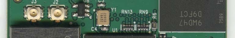

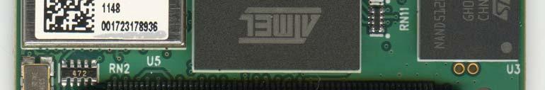

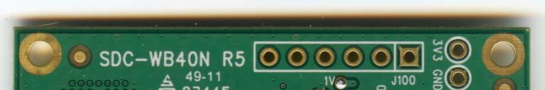


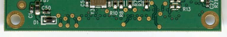
227 Elliott Laboratories -- EMC Department Test Report Report Date: March 14, 2012 APPENDIX D DETAILED PHOTOGRAPHS OF CONSTRUCTION Top view Bottom view File R85917 Page 227 of 229


228 Elliott Laboratories -- EMC Department Test Report Report Date: March 14, 2012 Without Shield File R85917 Page 228 of 229
Test Report LP0002 ( ) Summit Data Communications Device Name:SDC-MSD40NBT Brand: Summit Data Communications Model: SDC-MSD40NBT
 Summit Data Communications Device Name:SDC-MSD40NBT Brand: Summit Data Communications Model: SDC-MSD40NBT") Test Report LP0002 (100-06-28) Summit Data Communications Device Name:SDC-MSD40NBT Brand: Summit Data Communications Model: SDC-MSD40NBT GRANTEE: TEST SITE: Summit Data Communications 526 South Main St.
Test Report LP0002 (100-06-28) Summit Data Communications Device Name:SDC-MSD40NBT Brand: Summit Data Communications Model: SDC-MSD40NBT GRANTEE: TEST SITE: Summit Data Communications 526 South Main St.
EMC Test Report Application for Grant of Equipment Authorization Industry Canada RSS-Gen Issue 3 / RSS 210 Issue 8 FCC Part 15 Subpart C
 EMC Test Report Application for Grant of Equipment Authorization Industry Canada RSS-Gen Issue 3 / RSS 210 Issue 8 FCC Part 15 Subpart C Model: SDC-WB40NBT IC CERTIFICATION #: FCC ID: 6616A-SDCWB40NBT
EMC Test Report Application for Grant of Equipment Authorization pursuant to Industry Canada RSS-Gen Issue 2 / RSS 210 Issue 7 FCC Part 15 Subpart C
 EMC Test Report Application for Grant of Equipment Authorization pursuant to Industry Canada RSS-Gen Issue 2 / RSS 210 Issue 7 FCC Part 15 Subpart C IC CERTIFICATION #: FCC ID: APPLICANT: TEST SITE(S):
EMC Test Report Application for Grant of Equipment Authorization Industry Canada RSS-Gen Issue 3 / RSS 210 Issue 8 FCC Part 15 Subpart C
 EMC Test Report Application for Grant of Equipment Authorization Industry Canada RSS-Gen Issue 3 / RSS 210 Issue 8 FCC Part 15 Subpart C Model: SDC-WB40NBT IC CERTIFICATION #: FCC ID: 6616A-SDCWB40NBT
4655 Great America Parkway Santa Clara, CA W. Maude Avenue Sunnyvale, CA Boyce Road. Fremont, CA.
 EMC Test Report Application for Grant of Equipment Authorization pursuant to Industry Canada RSS-Gen Issue 2 / RSS 210 Issue 7 FCC Part 15, Subpart E Model: WLAN AP 8120 IC CERTIFICATION #: FCC ID: APPLICANT:
Test Certificate. given the measurement uncertainties detailed in Elliott report R Summit Data Communications. Model SDC-MSD40NBT
 Test Certificate A sample of the following product received on September 1, 2011 and tested on October 8 and November 11, 2011 and January 20, 2012 complied with the requirements of EN 300 328 V1.7.1 Electromagnetic
EMC Test Report. Application for FCC Grant of Equipment Authorization Canada Certification
 EMC Test Report Application for FCC Grant of Equipment Authorization Canada Certification Innovation, Science and Economic Development Canada RSS-Gen Issue 4 / RSS 247 Issue 1 FCC Part 15, Subpart E ARRIS
Test Certificate. Summit Data Communications Model SDC-WB40NBT
 Test Certificate A sample of the following product received on October 19, 2010 and tested on October 8 and 26 and November 11, 2011 complied with the requirements of AS/NZS 4268:2008 +A1:2010 Radio equipment
EMC Test Report. Application for Grant of Equipment Authorization. Industry Canada RSS-Gen Issue 4 / RSS 247 Issue 1 FCC Part 15 Subpart C
 EMC Test Report Application for Grant of Equipment Authorization Industry Canada RSS-Gen Issue 4 / RSS 247 Issue 1 FCC Part 15 Subpart C IC CERTIFICATION #: FCC ID: 8542A-FB502 XRAFB502 APPLICANT: Fitbit,
EMC Test Report. Application for FCC Grant of Equipment Authorization. FCC Part 15 Subpart C. Model: KET-001
 41039 Boyce Road 510-578-3500 Phone Fremont, CA. 94538 510-440-9525 Fax EMC Test Report Application for FCC Grant of Equipment Authorization FCC Part 15 Subpart C Model: KET-001 FCC ID: 2AFEOSE2 APPLICANT:
EMC Test Report. Application for FCC Grant of Equipment Authorization Canada Certification Class II Permissive Change/Reassessment
 EMC Test Report Application for FCC Grant of Equipment Authorization Canada Certification Class II Permissive Change/Reassessment Innovation, Science and Economic Development Canada RSS-Gen Issue / RSS
Test Certificate. given the measurement uncertainties detailed in Elliott report R Summit Data Communications.
 Test Certificate A sample of the following product received on October 19, 2010 and tested on October 31 and November 11, 2011 and January 4, 2012 complied with the requirements of EN 301 893 V1.5.1 Broadband
Electromagnetic Emissions Test Report and Application for Grant of Equipment Authorization pursuant to
 Electromagnetic Emissions and Application for Grant of Equipment Authorization pursuant to Industry Canada RSS-Gen Issue 1 / RSS 210 Issue 6 FCC Part 15 Subpart C on the Meshdynamics Transmitter Model:
FCC CFR47 PART 15 SUBPART C INDUSTRY CANADA RSS-GEN AND RSS-210 CERTIFICATION TEST REPORT FOR BROADCOM BLUETOOTH MODULE MODEL NUMBER: BCM92046MD
 FCC CFR47 PART 15 SUBPART C INDUSTRY CANADA RSS-GEN AND RSS-210 CERTIFICATION TEST REPORT FOR BROADCOM BLUETOOTH MODULE MODEL NUMBER: BCM92046MD IC #: 4324A-BRCM1029 REPORT NUMBER: 07U11199-1C ISSUE DATE:
Test Certificate. given the measurement uncertainties detailed in Elliott report R Summit Data Communications. Model SDC-SSD40NBT
 Test Certificate A sample of the following product received on September 1, 2011 and tested on November 11, 2011 and January 4, 10, and 12, 2012 complied with the requirements of EN 301 893 V1.5.1 Broadband
Elliott Laboratories, Inc Boyce Road Fremont, CA REPORT DATE: September 8, FINAL TEST DATE: July 22, 2004
 Electromagnetic Emissions and Verification of Compliance per FCC Part 15, Subpart B Specifications for a Class B Digital Device and ICES-003 Class B on the PalmOne, Inc. Model: TREO 650 (CDMA) MANUFACTURER:
Measurement of RF Emissions from a Caterpillar Inc. MSS3s RF ID Key Fob
 Measurement of RF Emissions from a Caterpillar Inc. MSS3s RF ID Key Fob For Caterpillar Inc. 330 S.W. Adams Street Peoria, IL 61630 P.O. Number JBL 11260 Date Tested May 11, 2016 Test Personnel Mark Longinotti
EMC Test Report. Information Technology Equipment Class B Digital Device. FCC Part 15 Industry Canada ICES-003 Issue 4
 EMC Information Technology Equipment Class B Digital Device FCC Part 15 Industry Canada ICES-003 Issue 4 Intel Centrino Advanced-N 6235, Models 6235ANHMRW and 6235ANHRU FCC ID: PD96235ANHR and PD96235ANHRU
TRANSMITTER MODEL: KAS-2030M
 Page 1 of 16 FCC PART 15, SUBPART B and C TEST REPORT for TRANSMITTER MODEL: KAS-2030M Prepared for WILDLIFE TECHNOLOGIES 115 WOLCOTT STREET MANCHESTER, NEW HAMPSHIRE 03103 Prepared by: KYLE FUJIMOTO Approved
175 Science Parkway Rochester, NY W. Maude Avenue Sunnyvale, CA REPORT DATE: November 4, FINAL TEST DATE: October 31, 2008
 Electromagnetic Emissions In Accordance With Industry Canada Radio Standards Specification 119 Issue 6, FCC Part 90 on the GE MDS LLC Transmitter Model: SD4 FCC ID NUMBER: UPN: GRANTEE: TEST SITE: E5MDS-SD4
Radio Test Report. Industry Canada RSS MHz to 3700 MHz RSS 197. Model: NanoStationM365/NanoBridgeM365
 Radio Test Report Industry Canada RSS 197 3650 MHz to 3700 MHz RSS 197 Model: NanoStationM365/NanoBridgeM365 COMPANY: TEST SITE(S): Ubiquiti Networks 91 E. Tasman Drive San Jose, CA 95134 Elliott Laboratories
FCC CFR47 PART 15 SUBPART C INDUSTRY CANADA RSS-210 ISSUE 7 CERTIFICATION TEST REPORT FOR g WIRELESS LAN + BLUETOOTH PCI-E MINI CARD
 FCC CFR47 PART 15 SUBPART C INDUSTRY CANADA RSS-210 ISSUE 7 CERTIFICATION TEST REPORT FOR 802.11g WIRELESS LAN + BLUETOOTH PCI-E MINI CARD MODEL NUMBER: BCM94312HMGB REPORT NUMBER: 09U12439-2 ISSUE DATE:
L.S. Compliance, Inc. W66 N220 Commerce Court Cedarburg, WI
 L.S. Compliance, Inc. W66 N220 Commerce Court Cedarburg, WI 53012 262-375-4400 COMPLIANCE TESTING OF: Quartex Synchronization Transmitter Model FM-72 PREPARED FOR: Quartex, Division of Primex, Inc. 965
OUTDOOR SOUND MODULE/TRANSMITTER MODEL: THE BANDIT
 Page 1 of 16 FCC PART 15, SUBPART B and C TEST REPORT for OUTDOOR SOUND MODULE/TRANSMITTER MODEL: THE BANDIT Prepared for MINASKA OUTDOORS 6517 PLATTE AVENUE LINCOLN, NEBRASKA 68507 Prepared by: KYLE FUJIMOTO
Matric Limited Hill City Road R.R. #1 Box 421A Seneca, PA 16346
 FCC CERTIFICATION TEST REPORT for Hill City Road R.R. #1 Box 421A Seneca, PA 16346 FCC ID: K5B-TP105 May 14, 2001 Revised: June 18, 2001 WLL PROJECT #: 6182X This report may not be reproduced, except in
STC Test Report. Date : Page 1 of 13 No. : HM161169
 Date : 2009-05-11 Page 1 of 13 Applicant (ATS001): Atech Scientific Measurement Limited. Room A-C, 18 Floor, Luk Hop Ind. Bldg, 8 Luk Hop Street, Kowloon Manufacturer: Atech Scientific Measurement Limited.
FCC 47 CFR PART 15 SUBPART C INDUSTRY CANADA RSS-210 ISSUE 8 BLUETOOTH LOW ENERGY CERTIFICATION TEST REPORT FOR. 2.4GHz LE MODULE MODEL NUMBER: RN4020
 FCC 47 CFR PART 15 SUBPART C INDUSTRY CANADA RSS-210 ISSUE 8 BLUETOOTH LOW ENERGY CERTIFICATION TEST REPORT FOR 2.4GHz LE MODULE MODEL NUMBER: RN4020 REPORT NUMBER: 14U17191-1 ISSUE DATE: MARCH 21, 2014
RF Emissions Test Report To Determine Compliance With: FCC, Part 15 Rules and Regulations
 RF Emissions Test Report To Determine Compliance With: FCC, Part 15 Rules and Regulations Model numbers: HT130022 Rev. B. December 17, 2002 Manufacturer: HQ, Inc. 210 9th Steet Drive Palmetto, FL 34221
Version TEST REPORT NO. DATE DESCRIPTION
 Version NO. DATE DESCRIPTION HCTR1302FR13 February 14, 2013 - First Approval Report - Additional Model Name Page 2 of 25 Table of Contents 1. GENERAL INFORMATION... 4 2. EUT DESCRIPTION... 4 3. TEST METHODOLOGY...
FCC CFR47 PART 15 SUBPART C INDUSTRY CANADA RSS-247 ISSUE 1 BLUETOOTH LOW ENERGY CERTIFICATION TEST REPORT FOR
 FCC CFR47 PART 15 SUBPART C INDUSTRY CANADA RSS-247 ISSUE 1 BLUETOOTH LOW ENERGY CERTIFICATION TEST REPORT FOR WLAN 2X2 MIMO 802.11a/b/g/n/ac with BLUETOOTH MODEL NUMBER: P2180 REPORT NUMBER: 15U21878-E2V1
TEST REPORT. Table of Contents
 Page:2 of 43 Table of Contents 1. DOCUMENT POLICY AND TEST STATEMENT... 4 1.1 DOCUMENT POLICY... 4 1.2 TEST STATEMENT... 4 2. DESCRIPTION OF EUT AND TEST MODE... 4 2.1 GENERAL DESCRIPTION OF EUT... 4 2.2
FCC CFR47 PART 15 SUBPART C INDUSTRY CANADA RSS-210 ISSUE 8 CERTIFICATION TEST REPORT FOR
 FCC CFR47 PART 15 SUBPART C INDUSTRY CANADA RSS-210 ISSUE 8 CERTIFICATION TEST REPORT FOR The Apple ipad is a tablet device with multimedia functions (music, application support, and video), 802.11a/b/g/n
Radio Frequency Exposure Test Report
 Radio Frequency Exposure EN 62311 January 2008 Assessment of electronic and electrical equipment related to human exposure restrictions for electromagnetic fields (0Hz 300GHz) (IEC 62311:2007, modified)
DATES OF TESTS: From 03/10/2014 to 20/10/2014 and 25/02/2015. Open area test site in Aunainville (28) - FRANCE. Page 2 out of 54
 - FRANCE. Page 2 out of 54") TEST CERTIFICATION FOR: FCC Certification NAME OF THE EQUIPMENT UNDER TEST: Serial number: Wireless conference access point Type: CONFIDEA WCAP G3 1440077150000C1 Reference / model (P/N): 71.98.0033 V
TEST CERTIFICATION FOR: FCC Certification NAME OF THE EQUIPMENT UNDER TEST: Serial number: Wireless conference access point Type: CONFIDEA WCAP G3 1440077150000C1 Reference / model (P/N): 71.98.0033 V
FCC & IC Certification. Test Report. FCC & Industry Canada Certification. Test Report. for Hetronic USA FCC ID: LW9-CS434TXN IC ID: 2219A-CS434TXN
 FCC & IC Certification Test Report FCC & Industry Canada Certification Test Report for Hetronic USA March 3, 2005 Prepared for: Hetronic USA 4300 Highline Blvd Building 4 Oklahoma City, OK 73108 Prepared
Measurement of RF Interference from a Canopy 900MHz Access Point and Subscriber Module Using A Yagi Antenna
 Measurement of RF Interference from a Canopy 900MHz Access Point and Subscriber Module Using A Yagi Antenna For : Motorola, Inc. 1301 East Algonquin Road Schaumburg, IL 60196 P.O. No. : 40335 Date Tested
Nemko-CCL, Inc West Alexander Street Salt Lake City, UT
 Nemko-CCL, Inc. 1940 West Alexander Street Salt Lake City, UT 84119 801-972-6146 Test Report Declaration of Conformity Test Of: MICRO-RM2.4-LB Test Specification: FCC PART 15, Subpart B ICES-003, Issue
ECHOSTAR 54.0 BRISBANE VOICE REMOTE 2017 MODEL: URC-2027BC0-R
 Page 1 of 17 FCC PART 15, SUBPART B and C TEST REPORT for ECHOSTAR 54.0 BRISBANE VOICE REMOTE 2017 MODEL: URC-2027BC0-R Prepared for UNIVERSAL ELECTRONICS, INC. 201 E. SANDPOINTE, 8 TH FLOOR SANTA ANA,
7. Transmitter Radiated Spurious Emissions and Conducted Spurious Emission
 7. Transmitter Radiated Spurious Emissions and Conducted Spurious Emission 7.1 Test Setup Refer to the APPENDIX I. 7.2 Limit According to 15.247(d), in any 100 khz bandwidth outside the frequency band
EMC Test Data. Radio Test Report R Summit Data Communications SDC-MCF10G. Test Report R76253 Rev 3.0. Revision History.
 EMC Test Data Radio Test Report R76253 For The Summit Data Communications Model SDC-MCF10G Revision History Rev # Made By Date Comments 1.0 Mark Hill 31-Jul-09 Initial Release 2.0 Mark Briggs 11-Aug-09
Medtronic MiniMed TEST REPORT FOR. GST3 Glucose Sensor Transmitter, MMT-7763A. Tested To The Following Standards:
 Medtronic MiniMed TEST REPORT FOR GST3 Glucose Sensor Transmitter, MMT-7763A Tested To The Following Standards: FCC Part 15 Subpart C Sections 15.247 Date of issue: October 31, 2013 This test report bears
SHENZHEN LCS COMPLIANCE TESTING LABORATORY LTD. FCC ID: 2ADPC-G6 Report No.: LCS E
 2) Sequence of testing 30 to 1 GHz Setup: --- The equipment was set up to simulate a typical usage like described in the user manual or described by manufacturer. --- If the EUT is a tabletop system, a
Advanced Compliance Solutions, Inc FAU Blvd, Suite 310 Boca Raton, Florida (561)
") 2129.01 Advanced Compliance Solutions, Inc. 3998 FAU Blvd, Suite 310 Boca Raton, Florida 33431 (561) 961-5585 Technical Report No. 09-2067a-2 EMI Evaluation of the AMM Marketing, LLC s E-Pulse UH 900,
2129.01 Advanced Compliance Solutions, Inc. 3998 FAU Blvd, Suite 310 Boca Raton, Florida 33431 (561) 961-5585 Technical Report No. 09-2067a-2 EMI Evaluation of the AMM Marketing, LLC s E-Pulse UH 900,
XBee Series 2 OEM RF Module Model No.: XBEE2 FCC ID: OUR-XBEE2. Applicant: MaxStream, Inc. 355 South 520 West Suite 180 Lindon, UT 84042
 XBee Series 2 OEM RF Module Model No.: XBEE2 Applicant: MaxStream, Inc. 355 South 520 West Suite 180 Lindon, UT 84042 In Accordance With Federal Communications Commission (FCC) Part 15, Subpart C, Section
FCC CFR47 PART 15 SUBPART C CERTIFICATION TEST REPORT FOR DUAL RADIO OUTDOOR ACCESS POINT MODEL NUMBER: AP-ONE FCC ID: SWX-AP1R2
 FCC CFR47 PART 15 SUBPART C CERTIFICATION TEST REPORT FOR DUAL RADIO OUTDOOR ACCESS POINT MODEL NUMBER: AP-ONE REPORT NUMBER: 04U3091-1 ISSUE DATE: JANUARY 07, 2005 Prepared for UBIQUITI NETWORKS 1111
FCC 47 CFR PART 15 SUBPART C CERTIFICATION TEST REPORT FOR. Bluetooth Remote Control for Video Set Top Box MODEL NUMBER: IPRC1000 FCC ID: 2ABTE-L3YJC9
 FCC 47 CFR PART 15 SUBPART C CERTIFICATION TEST REPORT FOR Bluetooth Remote Control for Video Set Top Box MODEL NUMBER: IPRC1000 REPORT NUMBER: 15U22448-E1V4 ISSUE DATE: 3/7/2016 Prepared for Verizon Online
Quality Auditing Institute # Schoolhouse Street, Coquitlam, BC, V3K 4X9, Canada. ISO Accreditation:
 CANADA: 16-211 Schoolhouse Street Coquitlam, British Columbia Canada V3K 4X9 ELECTROMAGNETIC COMPATIBILITY TEST REPORT TO CFR 47 FCC Part 15, Subpart C, Section 15.225 Industry Canada RSS 210, Issue 8
Radio Frequency Exposure Test Report
 Radio Frequency Exposure EN 62311 January 2008 Assessment of electronic and electrical equipment related to human exposure restrictions for electromagnetic fields (0Hz 300GHz) (IEC 62311:2007, modified)
COMMUNICATION CERTIFICATION LABORATORY 1940 West Alexander Street Salt Lake City, UT
 COMMUNICATION CERTIFICATION LABORATORY 1940 West Alexander Street Salt Lake City, UT 84119 801-972-6146 Test Report Certification TEST OF: LOZ-5S1-W FCC ID: R33LOZ5S11 To FCC PART 15, Subpart C (15.203,
Spectrian Dual Mode Cellular Power Amplifier Model No.: SCLPA 800 CR FCC ID: I2ONTHX51AA
 A Class II Permissive Change - FCC Part 22 Type Acceptance Test Report for Spectrian Dual Mode Cellular Power Amplifier Model No.: SCLPA 800 CR FCC ID: I2ONTHX51AA Date of Report: May 26, 1999 Total No.
TEST REPORT. For RFID READER/WRITER. In conformity with. FCC CFR 47 Part15 Subpart C
 TEST REPORT For RFID READER/WRITER In conformity with FCC CFR 47 Part15 Subpart C Model: TR3XM-SD01 / TR3XM-SU01 / TR3XM-SN01 FCC ID: MK4TR3XM-SX01 Test Item: RFID READER/WRITER Report No: RY1203Z12R1
FCC Test Report. : abgn M.2 module w/usb interface
 FCC Test Report FCC ID Equipment Model No. Brand Name Applicant : SQG-M2US50NBT : 802.11abgn M.2 module w/usb interface : M2US50NBT : Laird Technologies : Laird Technologies Address : 11160 Thompson Ave.,
FCC Test Report. Report No.: PTCDQ FC01
 Page 1 of 63 FCC Test Report Report No.: PTCDQ04170450501-FC01 FCC ID : 2AL2XW801 APPLICATION PURPOSE : Original Equipment PRODUCT DESIGNATION : WIFI DoorBell BRAND NAME : EASTIC MODEL NAME : W801, W802,
Compliance Engineering Ireland Ltd
 Page 1 of 27 Compliance Engineering Ireland Ltd RAYSTOWN, RATOATH ROAD, ASHBOURNE, CO. MEATH, IRELAND Tel: +353 1 8256722 Fax: +353 1 8256733 Project Number: 10E2475-5 Prepared for: Biancamed Ltd By Compliance
TABLE OF CONTENTS 1. GENERAL INFORMATION... 4
 TABLE OF CONTENTS 1. GENERAL INFORMATION... 4 1.1. EUT DESCRIPTION... 4 1.2. TEST STANDARDS AND RESULTS... 5 1.3. FACILITIES AND ACCREDITATIONS... 6 1.3.1. FACILITIES... 6 1.3.2. TEST ENVIRONMENT CONDITIONS...
FCC 47 CFR PART 15 SUBPART C INDUSTRY CANADA RSS-210 ISSUE 8 CERTIFICATION TEST REPORT FOR. Dolphin CT50
 FCC 47 CFR PART 15 SUBPART C INDUSTRY CANADA RSS-210 ISSUE 8 CERTIFICATION TEST REPORT FOR Dolphin CT50 MODEL NUMBER: CT50LFN IC ID: 1693B-CT50LFN REPORT NUMBER: 15U20259-E6 ISSUE DATE: JUNE 08, 2015 Prepared
FCC C2PC Test Report
 FCC C2PC Test Report FCC ID Equipment Model No. Brand Name Applicant : SQGBT800 : BTv4.0 Dual Mode USB Dongle : BT820 : Laird Technologies : Laird Technologies Address : 11160 Thompson Ave. / Lenexa, Kansas
F2 Labs Peters Road Middlefield, Ohio United States of America
 1674 Peters Road Middlefield, Ohio 4462 United States of America www.f2labs.com CERTIFICATION TEST REPORT Manufacturer: Applicant: Product Description: Libra Industries, Inc. 777 Division Drive Mentor,
Ave output power ANT 1(dBm) Ave output power ANT 2 (dbm)
 Ave output power ANT 2 (dbm)") Page 41 of 103 9.6. Test Result The test was performed with 802.11b Channel Frequency (MHz) power ANT 1(dBm) power ANT 2 (dbm) power ANT 1(mW) power ANT 2 (mw) Limits dbm / W Low 2412 7.20 7.37 5.248 5.458
Page 41 of 103 9.6. Test Result The test was performed with 802.11b Channel Frequency (MHz) power ANT 1(dBm) power ANT 2 (dbm) power ANT 1(mW) power ANT 2 (mw) Limits dbm / W Low 2412 7.20 7.37 5.248 5.458
IC Test Report. : 3147A-M2US50NBT : abgn M.2 module w/usb interface
 IC Test Report IC Equipment Model No. Brand Name Applicant : 3147A-M2US50NBT : 802.11abgn M.2 module w/usb interface : M2US50NBT : Laird Technologies : Laird Technologies Address : 11160 Thompson Ave.,
FCC PART & IC RSS GHz FHSS TEST REPORT
 FCC PART 15.247 & IC RSS-247 2.4 GHz FHSS TEST REPORT 849 NW State Road 45 Newberry, FL 32669 USA Ph.: 888.472.2424 or 352.472.5500 Fax: 352.472.2030 Email: info@timcoengr.com Website: www.timcoengr.com
APPROVED BY: DATE: 19-Aug-2011 Brian Boyea, EMC Engineer. TESTED BY: DATE: 12-Aug-2011 Arturo Ruvalcaba, EMC Engineer
 ENGINEERING TEST REPORT NUMBER: 102127174EUS1 ON Model No.(s): MAVRK IN ACCORDANCE WITH: CFR 47, PART 15, SUBPART B, TESTED FOR: Texas Instruments, Inc. 12500 TI Boulevard MS 8712 Dallas TX 75243 TESTED
TRANSMITTER Model: TX24
 FCC Part 15 Subpart B and FCC Section 15.231 Test Report Page 1 of 17 FCC PART 15 SUBPART B and C TEST REPORT for TRANSMITTER Prepared for FOPRO, INC. 14 FO HOLLOW DRIVE LEWISTOWN, PENNSYLVNIA 17044 Prepared
RADIO TEST REPORT. For MODEL NO FCC ID: C3K1703 IC ID: 3048A Test Report No. R-TR190-FCCIC-UNII-1 Issue Date: 14 September 2015
 RADIO TEST REPORT For MODEL NO. 1703 FCC ID: C3K1703 IC ID: 3048A-1703 Test Report No. R-TR190-FCCIC-UNII-1 Issue Date: 14 September 2015 FCC CFR47 Part 15 Subpart E Industry Canada RSS-247 Issue 1 Prepared
FCC 15B Test Report. : Bluetooth 4.2 Dual Mode USB HCI Module (Refer to item for more details) (Refer to item for more details)
 (Refer to item for more details)") FCC 15B Test Report Equipment Model No. Brand Name Applicant Address Standard : Bluetooth 4.2 Dual Mode USB HCI Module (Refer to item 1.1.1 for more details) : BT850-SA (Refer to item 1.1.1 for more details)
FCC 15B Test Report Equipment Model No. Brand Name Applicant Address Standard : Bluetooth 4.2 Dual Mode USB HCI Module (Refer to item 1.1.1 for more details) : BT850-SA (Refer to item 1.1.1 for more details)
SHURE ELECTROMAGNETIC COMPATIBILITY LABORATORY TEST REPORT
 SHURE ELECTROMAGNETIC COMPATIBILITY LABORATORY TEST REPORT TEST REPORT TITLE: Electromagnetic Compatibility Tests of the Shure QLXD2-V50 Handheld Transmitter TEST ITEM DESCRIPTION: QLXD2-V50 is a digital
FCC CFR47 PART 15 SUBPART C CERTIFICATION TEST REPORT FOR PCMCIA RFID READER CARD MODEL NUMBER: MPR6000 FCC ID: NTTWJMPR6XXX REPORT NUMBER: 04U2954-3
 FCC CFR47 PART 15 SUBPART C CERTIFICATION TEST REPORT FOR PCMCIA RFID READER CARD MODEL NUMBER: MPR6000 FCC ID: NTTWJMPR6XXX REPORT NUMBER: 04U2954-3 ISSUE DATE: NOVEMBER 22, 2004 Prepared for WJ COMUNICATIONS
Test Report Version. Test Report No. Date Description. DRTFCC Sep. 12, 2014 Initial issue
 DEMC1407-02828 FCC ID: 2AAAQH660W Test Report Version Test Report No. Date Description DRTFCC1409-1165 Sep. 12, 2014 Initial issue Page 2 DEMC1407-02828 FCC ID: 2AAAQH660W Table of Contents 1. EUT DESCRIPTION...
Certification Test Report
 Certification Test Report FCC ID: U9O-SM220 IC: 7084A-SM220 FCC Rule Part: 15.247 IC Radio Standards Specification: RSS-210 ACS Report Number: 14-2066.W06.1B Applicant: Synapse Wireless, Inc. Model(s):
Page 1 of 20 No.: HM TEST REPORT FCC PART 15 SUBPART C CERTIFICATION REPORT FOR LOW POWER TRANSMITTER. TEST REPORT No.
 Page 1 of 20 FCC PART 15 SUBPART C CERTIFICATION REPORT FOR LOW POWER TRANSMITTER Equipment Under Test [EUT]: Model Number: Applicant: FCC ID : Radio Controlled Tank FH002 Zhongshan Fu Hai Electronics
FCC Radio Test Report. Orpak Systems Ltd.
 DATE: 20 December 2015 I.T.L. (PRODUCT TESTING) LTD. FCC Radio Test Report for Orpak Systems Ltd. Equipment under test: Fuel Pump Nozzle Reader NNR EXTRA LARGE+SWITCH; NNR EXTRA LARGE* *See customer s
FCC & RSS-216 (Class II Permissive Change) Wireless Power Transfer Report. for A Acer Incorporated
 Wireless Power Transfer Report. for A Acer Incorporated") Page 1 of 17 FCC 15.209 & RSS-216 (Class II Permissive Change) Wireless Power Transfer Report for A Acer Incorporated 8F., No.88, Sec. 1, Xintai 5th Rd., Xizhi, New Taipei City 22181, Taiwan (R.O.C) Product
Page 1 of 17 FCC 15.209 & RSS-216 (Class II Permissive Change) Wireless Power Transfer Report for A Acer Incorporated 8F., No.88, Sec. 1, Xintai 5th Rd., Xizhi, New Taipei City 22181, Taiwan (R.O.C) Product
Page 1 of 51 Report No.: T TEST REPORT FCC ID: 2AGJ5WAP-30. In Accordance with: FCC PART 15, SUBPART C : 2015 (Section 15.
 Page 1 of 51 Report No.: T1851663 01 TEST REPORT FCC ID: 2AGJ5WAP-30 Applicant Address : Gonsin Conference Equipment Co., Ltd : No.401-406,Block C, Idea Industry Park, No.41 Fengxiang Road, Shunde, Foshan,
Palstar, Inc. EMC TEST REPORT FOR. HF LDMOS Amplifier Model: LA-1K. Tested To The Following Standard: FCC Part 97 Subpart D. Report No.
 Palstar, Inc. EMC TEST REPORT FOR HF LDMOS Amplifier Model: LA-1K Tested To The Following Standard: FCC Part 97 Subpart D Date of issue: November 28, 2017 This test report bears the accreditation symbol
Table of Contents 1. GENERAL INFORMATION SYSTEM TEST CONFIGURATION CONDUCTED EMISSIONS TEST RADIATED EMISSION TEST...
 Table of Contents 1. GENERAL INFORMATION... 4 1.1 PRODUCT DESCRIPTION FOR EQUIPMENT UNDER TEST... 4 1.2 RELATED SUBMITTAL(S) / GRANT (S)... 7 1.3 TEST METHODOLOGY... 7 1.4 EQUIPMENT MODIFICATIONS... 7
EMC Test Report. Tested by: Jeremy O. Pickens, Senior EMC Engineer. Reviewed by: David Schramm, EMC/RF/SAR/HAC Manager
 Page: 1 of 24 EMC Test Report Project Number: 4104971 Report Number: 4104971EMC01 Revision Level: 0 Client: Tier One, Inc. Equipment Under Test: GEN4 Glock Sensor Model Number: BA10232 FCC ID: 2AJ3810232
REVISION HISTORY. The revision history for this document is shown in table. HCT-EM-1801-FC037 January 22, 2018 Initial Release
 REVISION HISTORY The revision history for this document is shown in table. Version Issue Date Description HCT-EM-1801-FC037 January 22, 2018 Initial Release HCT-EM-1801-FC037-R1 January 26, 2018 Revision
FCC Rules and Regulations / Intentional Radiators. Operational in the MHz, MHz, MHz, and
 FCC Rules and Regulations / Intentional Radiators Operational in the 902-928 MHz, 2400-2483.5 MHz, 5725-5875 MHz, and 24.0-24.25 GHz Bands Part 15, Subpart C, Section 15.249 THE FOLLOWING MEETS THE ABOVE
C E R T I F I C A T I O N
 C E R T I F I C A T I O N Applicant Address Manufacturer Address : American Power Conversion Holding Inc. Taiwan Branch : 3F., No. 205, Sec. 3, Beixin Rd., Xindian Dist., New Taipei City 231, Taiwan R.O.C.
Chapter I - Federal Communications Commission Subchapter A - General Part 15 - Radio Frequency Devices Subpart C - Intentional Radiators
 www.nemko.com Report Reference ID 167484-1TRFWL Test specification Title 47 - Telecommunication Chapter I - Federal Communications Commission Subchapter A - General Part 15 - Radio Frequency Devices Subpart
FCC Test Report. Report No.: AGC FE08. Attestation of Global Compliance (Shenzhen) Co., Ltd
 Co., Ltd") Page 1 of 27 FCC Test Report Report No.: AGC01039170608FE08 FCC ID : PODTYT-X1U TYPE OF AUTHORIZATION : Certification APPLICATION PURPOSE : Original Equipment PRODUCT DESIGNATION : Analog Transceiver BRAND
Page 1 of 27 FCC Test Report Report No.: AGC01039170608FE08 FCC ID : PODTYT-X1U TYPE OF AUTHORIZATION : Certification APPLICATION PURPOSE : Original Equipment PRODUCT DESIGNATION : Analog Transceiver BRAND
Federal Communications Commission Office of Engineering and Technology Laboratory Division
 April 9, 2013 Federal Communications Commission Office of Engineering and Technology Laboratory Division Guidance for Performing Compliance Measurements on Digital Transmission Systems (DTS) Operating
Pico 900MHz 1W FHSS Module Model: p900 FCC ID: NS913P900. Applicant:
 Pico 900MHz 1W FHSS Module Model: p900 Applicant: Microhard Systems Inc. 150 Country Hills Landing NW Calgary, Alberta Canada T3K 5P3 In Accordance With Federal Communications Commission (FCC) Part 15,
TEST REPORT FROM RADIO FREQUENCY INVESTIGATION LTD.
 TEST REPORT FROM RADIO FREQUENCY INVESTIGATION LTD. Test Of: Wood & Douglas Ltd ST500 Transmitter Test Report Serial No: RFI/EMCB2/RP39403B This Test Report supersedes RFI Test Report No.: RFI/EMCB1/RP39403B
TEST REPORT. Table of Contents
 Page:2 of 28 Table of Contents 1. DOCUMENT POLICY AND TEST STATEMENT... 3 1.1 DOCUMENT POLICY... 3 1.2 TEST STATEMENT... 3 2. DESCRIPTION OF EUT AND TEST MODE... 4 2.1 GENERAL DESCRIPTION OF EUT... 4 2.2
1/41 IC: 109U-89FT7100
 SAMM No.0825 MOTOROLA PENANG ADV. COMM. LABORATORY FCC / IC TEST REPORT Motorola Solutions Malaysia Sdn. Bhd. Report Revision : Rev.A Innoplex Plot 2A Medan Bayan Lepas, Mukim 12, S.W.D. 11900 Bayan Lepas,
ELECTRICAL TESTING ACCORDING TO: FCC 47CFR part 15 subpart C (DTS) and subpart B FOR:
 and subpart B FOR:") ELECTRICAL TESTING 0839.01 Hermon Laboratories Ltd. P.O. Box 23, Binyamina 3055001, Israel Tel. +972 4628 8001 Fax. +972 4628 8277 E-mail: mail@hermonlabs.com TEST REPORT ACCORDING TO: FCC 47CFR part 15
ELECTRICAL TESTING 0839.01 Hermon Laboratories Ltd. P.O. Box 23, Binyamina 3055001, Israel Tel. +972 4628 8001 Fax. +972 4628 8277 E-mail: mail@hermonlabs.com TEST REPORT ACCORDING TO: FCC 47CFR part 15
As the responsible EMC Engineer, I hereby declare that the equipment tested as specified in this report conforms to the requirements indicated.
 MOBILE DEVICES BUSINESS PRODUCT SAFETY AND COMPLIANCE EMC LABORATORY EMC TEST REPORT Test Report Number 24262-1 WLAN Report Date December 17, 2010 The test results contained herein relate only to the model(s)
FCC ID: B4OCC264BPA-S
 FCC TEST REPORT FCC ID: B4OCC264BPA-S Product : Bluetooth LE Module Model Name : CC264BPA-S, CC265BPA-S, CC26xBPA Brand : GT-tronics Report No. : PTC801181160622E-FC01 Prepared for GT-tronics HK Ltd Unit
FCC 15B Test Report. : BTv4.0 Dual Mode USB Dongle. Address : Thompson Ave. / Lenexa, Kansas / / USA
 FCC 15B Test Report Equipment Model No. Brand Name Applicant : BTv4.0 Dual Mode USB Dongle : BT820 : Laird Technologies : Laird Technologies Address : 11160 Thompson Ave. / Lenexa, Kansas / 66219 / USA
FCC 47 CFR PART 15 SUBPART C
 FCC 47 CFR PART 15 SUBPART C Product Type Applicant Address Trade Name Model Number : Wink Relay : Quirky, Inc. : 606 W 28th St, Floor 7 New York NY 10001 United States : Wink : PRLAY-WH01 Test Specification
TEST REPORT. Covering the DYNAMIC FREQUENCY SELECTION (DFS) REQUIREMENTS OF. FCC Part 15 Subpart E (UNII) Summit Data Communications Inc SDC-MSD30AG
 REQUIREMENTS OF. FCC Part 15 Subpart E (UNII) Summit Data Communications Inc SDC-MSD30AG") TEST REPORT Covering the DYNAMIC FREQUENCY SELECTION (DFS) REQUIREMENTS OF FCC Part 15 Subpart E (UNII) Summit Data Communications Inc SDC-MSD30AG UPN: FCCID: COMPANY: TEST SITE: 6616A-SDCMSD30AG TWG-SDCMSD30AG
TEST REPORT Covering the DYNAMIC FREQUENCY SELECTION (DFS) REQUIREMENTS OF FCC Part 15 Subpart E (UNII) Summit Data Communications Inc SDC-MSD30AG UPN: FCCID: COMPANY: TEST SITE: 6616A-SDCMSD30AG TWG-SDCMSD30AG
TABLE OF CONTENTS SECTION TITLE PAGE. 5. LIST OF EUT, ACCESSORIES AND TEST EQUIPMENT 10 EUT and Accessory List EMI Test Equipment
 Page 2 of 14 TABLE OF CONTENTS SECTION TITLE PAGE GENERAL REPORT SUMMARY 04 SUMMARY OF TEST RESULTS 04 1. PURPOSE 05 2. ADMINISTRATIVE DATA 06 2.1 Location of Testing 06 2.2 Traceability Statement 06 2.3
UNIDEN AMERICA CORPORATION 4700 AMON CARTER BLVD. FORT WORTH TEXAS UNITED STATES
 849 NW STATE ROAD 45 NEWBERRY, FL 32669 USA PH: 888.472.2424 OR 352.472.5500 FAX: 352.472.2030 EMAIL: INFO@TIMCOENGR.COM HTTP://WWW.TIMCOENGR.COM TEST REPORT PER FCC Part 15, Subparts B, C, and D IC RSS-213
FCC PART 15C IC RSS-210, ISSUE 7, JUNE 2007 TEST AND MEASUREMENT REPORT. SunPower Corporation
 FCC PART 15C IC RSS-210, ISSUE 7, JUNE 2007 TEST AND MEASUREMENT REPORT For SunPower Corporation 1414 Harbour Way South, Richmond, CA 94804, USA FCC ID: YAW110884 IC: 8917A-110884 Report Type: Original
TEST REPORT. Table of Contents
 Page:2 of 24 Table of Contents 1. DOCUMENT POLICY AND TEST STATEMENT... 3 1.1 DOCUMENT POLICY...3 1.2 TEST STATEMENT...3 2. DESCRIPTION OF EUT AND TEST MODE... 4 2.1 GENERAL DESCRIPTION OF EUT...4 2.2
FCC 47 CFR PART 15 SUBPART C CERTIFICATION TEST REPORT FOR. RF ID Reader MODEL NUMBER: A-405 FCC ID: WFQITCS-A-405 IC: 10717A-ITCSA405
 FCC 47 CFR PART 15 SUBPART C CERTIFICATION TEST REPORT FOR RF ID Reader MODEL NUMBER: A-405 REPORT NUMBER: 10906664A ISSUE DATE: December 12, 2015 Prepared for RF Controls LLC 1400 S 3 RD Street Suite
RF test report AU01+W02
 Customer: Kehlbergstrasse 109 8054 Graz Austria Tel.: +43 664 415 6260 RF test report 170186-AU01+W02 The test result refers exclusively to the tested model. This test report may not be copied or published
CERTIFICATION TEST REPORT
 CERTIFICATION TEST REPORT Report Number. : 16U23813-E3V3 DTS Applicant : Model : FCC ID : IC : EUT Description : Test Standard(s) : APPLE, INC. 1 INFINITE LOOP CUPERTINO, CA 95014, U.S.A A1822 BCGA1822
UEI FUSION PLUS QWERTY KB REMOTE 2012 MODEL: URC-5110BC0-XXX-R
 Page 1 of 16 FCC PART 15 SUBPART B and C TEST REPORT for UEI FUSION PLUS QWERTY KB REMOTE 2012 MODEL: URC-5110BC0-XXX-R Prepared for UNIVERSAL ELECTRONICS, INC. 201 EAST SANDPOINTE AVENUE, 8 TH FLOOR SANTA