Notion of propagation of radio waves
|
|
|
- Jonas Heath
- 5 years ago
- Views:
Transcription


1 1 Notion of propagation of radio waves December 2016
2 2
3 I. Summary I. The Free-Space Path Loss (FSPL)... 7 II. The Fresnel zone... 8 III. Earth roundess... 9 IV. Fading/Reflection V. Case and results Optimal case No signal Power loss, lower range VI. Recommandations et conclusions VII. Figures table
4 4
5 Abstract An electric radio wave or radio wave is an electromagnetic wave. The first electromagnetic phenomenon was discovered by Hans Christian Orsted, a Danish chemist, in 1821 (Hans Christian Orsted, 1998). The radiocommunications domain is regulated by the International Telecommunication Union (ITU), which has established a Radio Regulations, as follows: «Radio waves or hertzian waves: electromagnetic waves whose frequency is by convention less than 300 GHz, propagating in space without artificial guide ; They are between 9 khz and 300 GHz which corresponds to wavelengths of 33 km to 1 mm.» There are two ways of propagating a radio wave or hertzian waves: - in free fields (propagation called radiated) - in power lines (guided propagation in a coaxial cable, for example) The propagation of a wave in a free space is more complex and results from various parameters. When radio equipment is used, it is important to optimize the reception of the signal and take into account the environment. 5 Four major elements are to be considered: - The Free-Space Path Loss (FSPL) - The Fresnel zone - The Earth roundess - Fading/Reflection - The environment (soil, climatic conditions) The first four elements will be presented. The consequences of the environment can not be explained because it depends on the field and the used frequency that makes it difficult to generalize. Key words : Radio, frequency, propagation, Fresnel zone, free-space path loss (FSPL)
6 6
.")

7 I. The Free-Space Path Loss (FSPL) In free fields, an electromagnetic wave reacts like a sound wave, it attenuates with distance. This is called the Free-Space Path Loss (FPPL). This attenuation is generally expressed in decibel (db) and follows the calculation below: FSPL = 20log10(d) log10(f) 2 147,55 db can be converted to distance, as: 3 db = Distance/ 2 6 db = Distance/2 10 db = Distance/3,16 7 Figure 1: Representation of the Free-Space Path Loss, Xerius d = distance between transmitter and receiver 2 f = frequency
8 II. The Fresnel zone The Fresnel zone help to determine the ellipsoid between a receiver and a transmitter in the context of a transmission of a radio signal. In the case where an obstacle is located in this ellipsoid, the signal will be attenuated. The scope will therefore be less. D (distance) r (radius) Figure 2: Representation of the Fresnel zone, Xerius 2016 Consider D as the distance between the receiver and the transmitter and r as the radius of the ellipsoid. It is enough to calculate the radius r to know where to place the receiver to have the maximum power. Receiver altitude can be calculated as show below: 8 r = 3 D = c4 f = /f 5 For examples : With D = 10kms and Stratus I in 234,5 MHz r = 113 m With D = 10kms and Stratus II in 220 MHz r = 117 m 3 is equal to the celerity divised by the frequency 4 c is equal to 3* f is the used frequency
9 III. Earth roundess In addition to taking into account the elements mentioned above, it also must consider that the Earth is round. d1 D (distance) d2 9 Figure 3 : Representation of the Earth roundess, Xerius 2016 We can estimate it, following the calculation below : r x = D (r 6 arccos ( r + d1 )) 1 d2 = r( cos ( x r ) 1) For examples : With D = 10kms and d1 = 60 m d2 = 25 m With D = 200kms and d1 = 1000 m d2 = 596 m 6 r is Earth radius km
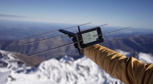
10 IV. Fading/Reflection An electromagnetic wave can be reflected in some environments. This action is called fading or reflection. Position deducted by the receiver Obstacle Figure 4: Representation of fading, Xerius 2016 To avoid this phenomenon during study, the tracking tags are equipped with GPS inside. The coordinates of the species are sent via UHF/VHF to the receiver. It eliminates the risk of fading. Reflections or fading consequences are power loss to the signal and therefore to the range. 10
 Same power Range of 107kms between receiver and transmitter 11 2.")
11 V. Case and results 1. Optimal case Figure 5: Optimal case, Xerius 2016 Results : Radio signal is Line of Sight (LoS) Same power Range of 107kms between receiver and transmitter No signal Figure 6: Case without LoS, Xerius 2016 Results : Radio signal is not Line of Sight (LoS) No signal despite the distance of 1km between receiver and transmitter
12 3. Power loss, lower range Results : Figure 7: Case with obstacle on the Fresnel zone, Xerius 2016 Radio signal is Line of Sight (LoS) Obstacle in the Fresnel zone Power loss and, so, lower range 12 VI. Recommandations et conclusions In order to limit the impact of these factors and have the best signal, it is important to always be placed in elevated area. It's not because you do not have a signal a few meters away that your device is not working. Simply move and/or go in elevated area to intercept a signal. The impact of the environment is not taken into account but is not to be neglected.
13 VII. Figures table Figure 1: Representation of the Free-Space Path Loss, Xerius Figure 2: Representation of the Fresnel zone, Xerius Figure 3 : Representation of the Earth roundess, Xerius Figure 4: Representation of fading, Xerius Figure 5: Optimal case, Xerius Figure 6: Case without LoS, Xerius Figure 7: Case with obstacle on the Fresnel zone, Xerius
14 14
Radio Propagation Fundamentals
 Radio Propagation Fundamentals Concept of Electromagnetic Wave Propagation Mechanisms Modes of Propagation Propagation Models Path Profiles Link Budget Fading Channels Electromagnetic (EM) Waves EM Wave
Study of Factors which affect the Calculation of Co- Channel Interference in a Radio Link
 International Journal of Electronic and Electrical Engineering. ISSN 0974-2174 Volume 8, Number 2 (2015), pp. 103-111 International Research Publication House http://www.irphouse.com Study of Factors which
Link Budget Calculation
 Link Budget Calculation Training materials for wireless trainers This 60 minute talk is about estimating wireless link performance by using link budget calculations. It also introduces the Radio Mobile
Application Note No. 7 Radio Link Calculations (Link_Calc.xls)
") TIL-TEK Application Note No. 7 Radio Link Calculations (Link_Calc.xls) The following application note describes the application and utilization of the Link_Calc.xls worksheet. Link_Calc.xls is an interactive
TIL-TEK Application Note No. 7 Radio Link Calculations (Link_Calc.xls) The following application note describes the application and utilization of the Link_Calc.xls worksheet. Link_Calc.xls is an interactive
Point to point Radiocommunication
 Point to point Radiocommunication SMS4DC training seminar 7 November 1 December 006 1 Technical overview Content SMS4DC Software link calculation Exercise 1 Point-to-point Radiocommunication Link A Radio
COMMUNICATION SYSTEMS -I
 COMMUNICATION SYSTEMS -I Communication : It is the act of transmission of information. ELEMENTS OF A COMMUNICATION SYSTEM TRANSMITTER MEDIUM/CHANNEL: The physical medium that connects transmitter to receiver
Antennas and Propagation
 CMPE 477 Wireless and Mobile Networks Lecture 3: Antennas and Propagation Antennas Propagation Modes Line of Sight Transmission Fading in the Mobile Environment Introduction An antenna is an electrical
6 Radio and RF. 6.1 Introduction. Wavelength (m) Frequency (Hz) Unit 6: RF and Antennas 1. Radio waves. X-rays. Microwaves. Light
 Frequency (Hz) Unit 6: RF and Antennas 1. Radio waves. X-rays. Microwaves. Light") 6 Radio and RF Ref: http://www.asecuritysite.com/wireless/wireless06 6.1 Introduction The electromagnetic (EM) spectrum contains a wide range of electromagnetic waves, from radio waves up to X-rays (as
6 Radio and RF Ref: http://www.asecuritysite.com/wireless/wireless06 6.1 Introduction The electromagnetic (EM) spectrum contains a wide range of electromagnetic waves, from radio waves up to X-rays (as
Data and Computer Communications. Tenth Edition by William Stallings
 Data and Computer Communications Tenth Edition by William Stallings Data and Computer Communications, Tenth Edition by William Stallings, (c) Pearson Education - Prentice Hall, 2013 Wireless Transmission
EEG 816: Radiowave Propagation 2009
 Student Matriculation No: Name: EEG 816: Radiowave Propagation 2009 Dr A Ogunsola This exam consists of 5 problems. The total number of pages is 5, including the cover page. You have 2.5 hours to solve
Intro to Radio Propagation,Antennas and Link Budget
 Intro to Radio Propagation,Antennas and Link Budget Training materials for wireless trainers Marco Zennaro and Ermanno Pietrosemoli T/ICT4D Laboratory ICTP Behavior of radio waves There are a few simple
Annex 5. Determination of the interference field strength in the Land Mobile Service
 Annex 5 Determination of the interference field strength in the Land Mobile Service Annex 5, page 2 of 18 1 General 1.1 This calculation method is based on Recommendation ITU-R P.1546, taking into account
Technical Note: Path Align-R Wireless Supporting Information
 Technical Note: Path Align-R Wireless Supporting Information Free-space Loss The Friis free-space propagation equation is commonly used to determine the attenuation of a signal due to spreading of the
This Antenna Basics reference guide includes basic information about antenna types, how antennas work, gain, and some installation examples.
 Antenna Basics This Antenna Basics reference guide includes basic information about antenna types, how antennas work, gain, and some installation examples. What Do Antennas Do? Antennas transmit radio
UNIT Derive the fundamental equation for free space propagation?
 UNIT 8 1. Derive the fundamental equation for free space propagation? Fundamental Equation for Free Space Propagation Consider the transmitter power (P t ) radiated uniformly in all the directions (isotropic),
ECC Recommendation (16)04
04") ECC Recommendation (16)04 Determination of the radiated power from FM sound broadcasting stations through field strength measurements in the frequency band 87.5 to 108 MHz Approved 17 October 2016 Edition
ECC Recommendation (16)04 Determination of the radiated power from FM sound broadcasting stations through field strength measurements in the frequency band 87.5 to 108 MHz Approved 17 October 2016 Edition
Antennas and Propagation
 Antennas and Propagation Chapter 5 Introduction An antenna is an electrical conductor or system of conductors Transmission - radiates electromagnetic energy into space Reception - collects electromagnetic
PART 1 RECOMMENDATION ITU-R P.1144 GUIDE TO THE APPLICATION OF THE PROPAGATION METHODS OF RADIOCOMMUNICATION STUDY GROUP 3
 Rec. ITU-R P.1144 1 PART 1 SECTION P-A: TEXTS OF GENERAL INTEREST Rec. ITU-R P.1144 RECOMMENDATION ITU-R P.1144 GUIDE TO THE APPLICATION OF THE PROPAGATION METHODS OF RADIOCOMMUNICATION STUDY GROUP 3 (1995)
Rec. ITU-R P RECOMMENDATION ITU-R P PROPAGATION BY DIFFRACTION. (Question ITU-R 202/3)
") Rec. ITU-R P.- 1 RECOMMENDATION ITU-R P.- PROPAGATION BY DIFFRACTION (Question ITU-R 0/) Rec. ITU-R P.- (1-1-1-1-1-1-1) The ITU Radiocommunication Assembly, considering a) that there is a need to provide
Rec. ITU-R P.- 1 RECOMMENDATION ITU-R P.- PROPAGATION BY DIFFRACTION (Question ITU-R 0/) Rec. ITU-R P.- (1-1-1-1-1-1-1) The ITU Radiocommunication Assembly, considering a) that there is a need to provide
Topic 5: Radio wave propagation and safety issues
 6. Short-distance link design, Fresnel ellipsoide. Topic 5: Radio wave propagation and safety issues A 6. 10-km Short-distance link system, link see design, figures Fresnel 1) and 3) ellipsoide. below,
RVRUSA - DATA DE REFERENCIA PARA INGENIEROS
 Useful formulae Electrical formulae Electrical power in KW: DC power [KW]: YROW DPSHUH YROW DPSHUH AC power (single phase) [KW]: AC power (three-phase) [KW]: where: cos( j ) YROW DPSHUH 73. cos( j) Volt:
Using the epmp Link Budget Tool
 Using the epmp Link Budget Tool The epmp Series Link Budget Tool can offer a help to determine the expected performances in terms of distances of a epmp Series system operating in line-of-sight (LOS) propagation
Chapter 4 The RF Link
 Chapter 4 The RF Link The fundamental elements of the communications satellite Radio Frequency (RF) or free space link are introduced. Basic transmission parameters, such as Antenna gain, Beamwidth, Free-space
DEVELOPMENT OF SOFTWARE FOR THE BASIC LINE-OF-SIGHT PARAMETERS CALCULATION
 DEVELOPMENT OF SOFTWARE FOR THE BASIC LINE-OF-SIGHT PARAMETERS CALCULATION,, {abidur@nstu.edu.bd, zmozumder@du.ac.bd} Abstract: In this paper we have developed a software by which the general parameter
Unguided Transmission Media
 CS311 Data Communication Unguided Transmission Media by Dr. Manas Khatua Assistant Professor Dept. of CSE IIT Jodhpur E-mail: manaskhatua@iitj.ac.in Web: http://home.iitj.ac.in/~manaskhatua http://manaskhatua.github.io/
The better WLAN Radio Network by an optimal Antenna System
 The better WLAN Radio Network by an optimal Antenna System BU Antennas ASY H&S Antennen mme / Pfad...ppt 1 www.hubersuhner.com www.hubersuhner.com The better radio network by optimal antennas What is an
Antennas and Propagation. Chapter 5
 Antennas and Propagation Chapter 5 Introduction An antenna is an electrical conductor or system of conductors Transmission - radiates electromagnetic energy into space Reception - collects electromagnetic
Antennas and Propagation. Chapter 5
 Antennas and Propagation Chapter 5 Introduction An antenna is an electrical conductor or system of conductors Transmission - radiates electromagnetic energy into space Reception - collects electromagnetic
Chapter-15. Communication systems -1 mark Questions
 Chapter-15 Communication systems -1 mark Questions 1) What are the three main units of a Communication System? 2) What is meant by Bandwidth of transmission? 3) What is a transducer? Give an example. 4)
Semi-Automated Microwave Radio Link Planning Tool
 Semi-Automated Microwave Radio Link Planning Tool W.M.D.R. Gunathilaka, H.G.C.P. Dinesh, K.M.M.W.N.B. Narampanawe Abstract Link Budget is a main estimate in telecommunication microwave link planning for
Session2 Antennas and Propagation
 Wireless Communication Presented by Dr. Mahmoud Daneshvar Session2 Antennas and Propagation 1. Introduction Types of Anttenas Free space Propagation 2. Propagation modes 3. Transmission Problems 4. Fading
Outline / Wireless Networks and Applications Lecture 3: Physical Layer Signals, Modulation, Multiplexing. Cartoon View 1 A Wave of Energy
 Outline 18-452/18-750 Wireless Networks and Applications Lecture 3: Physical Layer Signals, Modulation, Multiplexing Peter Steenkiste Carnegie Mellon University Spring Semester 2017 http://www.cs.cmu.edu/~prs/wirelesss17/
Antenna Basics. Antennas. A guide to effective antenna use
 A guide to effective antenna use Antennas Antennas transmit radio signals by converting radio frequency electrical currents into electromagnetic waves. Antennas receive the signals by converting the electromagnetic
Data and Computer Communications Chapter 4 Transmission Media
 Data and Computer Communications Chapter 4 Transmission Media Ninth Edition by William Stallings Data and Computer Communications, Ninth Edition by William Stallings, (c) Pearson Education - Prentice Hall,
Unguided Media and Matched Filter After this lecture, you will be able to Example?
 Unguided Media and Matched Filter After this lecture, you will be able to describe the physical and transmission characteristics of various unguided media Example? B.1 Unguided media Guided to unguided
Antenna & Propagation. Basic Radio Wave Propagation
 For updated version, please click on http://ocw.ump.edu.my Antenna & Propagation Basic Radio Wave Propagation by Nor Hadzfizah Binti Mohd Radi Faculty of Electric & Electronics Engineering hadzfizah@ump.edu.my
Antennas and Propagation
 Mobile Networks Module D-1 Antennas and Propagation 1. Introduction 2. Propagation modes 3. Line-of-sight transmission 4. Fading Slides adapted from Stallings, Wireless Communications & Networks, Second
BASICS OF ANTENNAS Lecture Note 1
 BASICS OF ANTENNAS Lecture Note 1 INTRODUCTION Antennas are devices that are capable of launching RF (radio frequency) energy into space and detect it as well. How well an antenna is able to launch RF
Allocation of electromagnetic spectrum
 Allocation of electromagnetic spectrum λ= = f 1 In the figure, λ = c/f, where: λ is the wavelength in meters; c is the propagation speed of light (identical to that of a radio wave) in meters per second
Colubris Networks. Antenna Guide
 Colubris Networks Antenna Guide Creation Date: February 10, 2006 Revision: 1.0 Table of Contents 1. INTRODUCTION... 3 2. ANTENNA TYPES... 3 2.1. OMNI-DIRECTIONAL ANTENNA... 3 2.2. DIRECTIONAL ANTENNA...
Determination of Propagation Path Loss and Contour Map for Adaba FM Radio Station in Akure Nigeria
 International Journal of Science and Technology Volume 2 No. 9, September, 2013 Determination of Propagation Path Loss and Contour Map for Adaba FM Radio Station in Akure Nigeria Oyetunji S. A, Alowolodu
Antennas and Propagation. Prelude to Chapter 4 Propagation
 Antennas and Propagation Prelude to Chapter 4 Propagation Introduction An antenna is an electrical conductor or system of conductors for: Transmission - radiates electromagnetic energy into space (involves
3 Methods of radiocommunication
 + + & & * * ) ) From the ITU Emergency Telecommunications handbook; prepared for the 54 th JOTA 2011. 3 Methods of radiocommunication 3.1 Frequencies Radio frequencies should be selected according to propagation
Chapter 1: Telecommunication Fundamentals
 Chapter 1: Telecommunication Fundamentals Block Diagram of a communication system Noise n(t) m(t) Information (base-band signal) Signal Processing Carrier Circuits s(t) Transmission Medium r(t) Signal
Basic Radio Physics. Developed by Sebastian Buettrich. ItrainOnline MMTK 1
 Basic Radio Physics Developed by Sebastian Buettrich 1 Goals Understand radiation/waves used in wireless networking. Understand some basic principles of their behaviour. Apply this understanding to real
Antennas & Propagation. CSG 250 Fall 2007 Rajmohan Rajaraman
 Antennas & Propagation CSG 250 Fall 2007 Rajmohan Rajaraman Introduction An antenna is an electrical conductor or system of conductors o Transmission - radiates electromagnetic energy into space o Reception
Rec. ITU-R P RECOMMENDATION ITU-R P *
 Rec. ITU-R P.682-1 1 RECOMMENDATION ITU-R P.682-1 * PROPAGATION DATA REQUIRED FOR THE DESIGN OF EARTH-SPACE AERONAUTICAL MOBILE TELECOMMUNICATION SYSTEMS (Question ITU-R 207/3) Rec. 682-1 (1990-1992) The
Project = An Adventure : Wireless Networks. Lecture 4: More Physical Layer. What is an Antenna? Outline. Page 1
 Project = An Adventure 18-759: Wireless Networks Checkpoint 2 Checkpoint 1 Lecture 4: More Physical Layer You are here Done! Peter Steenkiste Departments of Computer Science and Electrical and Computer
RECOMMENDATION ITU-R P Guide to the application of the propagation methods of Radiocommunication Study Group 3
 Rec. ITU-R P.1144-2 1 RECOMMENDATION ITU-R P.1144-2 Guide to the application of the propagation methods of Radiocommunication Study Group 3 (1995-1999-2001) The ITU Radiocommunication Assembly, considering
RECOMMENDATION ITU-R F.1819
 Rec. ITU-R F.1819 1 RECOMMENDATION ITU-R F.1819 Protection of the radio astronomy service in the 48.94-49.04 GHz band from unwanted emissions from HAPS in the 47.2-47.5 GHz and 47.9-48.2 GHz bands * (2007)
Prediction of clutter loss
 Recommendation ITU-R P.2108-0 (06/2017) Prediction of clutter loss P Series Radiowave propagation ii Rec. ITU-R P.2108-0 Foreword The role of the Radiocommunication Sector is to ensure the rational, equitable,
3C5 Telecommunications. what do radios look like? mobile phones. Linda Doyle CTVR The Telecommunications Research Centre
 3C5 Telecommunications what do radios look like? Linda Doyle CTVR The Telecommunications Research Centre ledoyle@tcd.ie Oriel/Dunlop House 2009 mobile phones talk is cheap.. bluetooth 3G WLAN/802.11 GSM
Announcements : Wireless Networks Lecture 3: Physical Layer. Bird s Eye View. Outline. Page 1
 Announcements 18-759: Wireless Networks Lecture 3: Physical Layer Please start to form project teams» Updated project handout is available on the web site Also start to form teams for surveys» Send mail
LCL, Radiation, and Radiation Resistance
 LCL, Radiation, and Radiation Resistance Some thoughts on how to determine antenna or cable radiation, ideas which may not necessarily represent the opinion of IARU At first we should have a look at Fig
Wireless systems. includes issues of
 Wireless systems includes issues of hardware processors, storage, peripherals, networks,... representation of information, analog vs. digital, bits & bytes software applications, operating system organization
Engineering Discovery
 Modeling, Computing, & Measurement: Measurement Systems # 4 Dr. Kevin Craig Professor of Mechanical Engineering Rensselaer Polytechnic Institute 1 Frequency Response and Filters When you hear music and
Applying ITU-R P.1411 Estimation for Urban N Network Planning
 Progress In Electromagnetics Research Letters, Vol. 54, 55 59, 2015 Applying ITU-R P.1411 Estimation for Urban 802.11N Network Planning Thiagarajah Siva Priya, Shamini Pillay Narayanasamy Pillay *, Vasudhevan
November 24, 2010xx. Introduction
 Path Analysis XXXXXXXXX Ref Number: XXXXXXX Introduction This report is an analysis of the proposed XXXXXXXXX network between XXXXXXX and XXXXXXX. The primary aim was to investigate the frequencies and
Structure of the Lecture
 Structure of the Lecture Chapter 2 Technical Basics: Layer 1 Methods for Medium Access: Layer 2 Representation of digital signals on an analogous medium Signal propagation Characteristics of antennas Chapter
UHF Wave Propagation Losses Beyond 40 Percent Fresnel Zone Radius in South-South, Nigeria
 UHF Wave Propagation Losses Beyond 40 Percent Fresnel Zone Radius in South-South, Nigeria D. E. Bassey 1, Aniefiok O. Akpan 2, E Udoeno 3 1 Electronics and Computer Technology Unit, Department of Physics,
Wave Propagation and Antenna Engineering
 Wave Propagation and Antenna Engineering Wave Propagation and Antenna Engineering SANJAY KUMAR Air Commodore (Retd.) Former AOC, 9 BRD, IAF Pune and Former Principal Adviser Defence Avionics Research
Intermediate Course (5) Antennas and Feeders
 Antennas and Feeders") Intermediate Course (5) Antennas and Feeders 1 System Transmitter 50 Ohms Output Standing Wave Ratio Meter Antenna Matching Unit Feeder Antenna Receiver 2 Feeders Feeder types: Coaxial, Twin Conductors
Intermediate Course (5) Antennas and Feeders 1 System Transmitter 50 Ohms Output Standing Wave Ratio Meter Antenna Matching Unit Feeder Antenna Receiver 2 Feeders Feeder types: Coaxial, Twin Conductors
Basic radio physics. Sebastian Büttrich, NSRC/ITU/wire.less.dk edit: June
 Basic radio physics Sebastian Büttrich, NSRC/ITU/wire.less.dk edit: June 2011 http://creativecommons.org/licenses/by-nc-sa/3.0/ Electromagnetic Fields Electromagnetic forces act between electric charges
SATELLITE COMMUNICATIONS
 SATELLITE COMMUNICATIONS Master of Management and Economics of Telecommunication Networks University of Athens - 006 The Link Budget by E. Rammos ESA Senior Advisor Satcom Courses University of Athens
Introduction to Wireless Signal Propagation
 Introduction to Wireless Signal Propagation Raj Jain Professor of Computer Science and Engineering Washington University in Saint Louis Saint Louis, MO 63130 Jain@cse.wustl.edu Audio/Video recordings of
Issues Associated with Decimeter Waves Propagation at 0.6, 1.0 and 2.0 Peak Fresnel Zone Levels
 Issues Associated with Decimeter Waves Propagation at 0.6, 1.0 and 2.0 Peak Fresnel Zone Levels D. E. Bassey 1, R. C. Okoro 2, B. E. Okon 3 1 Electronics and Computer Technology Unit, Department of Physics,
CS-435 spring semester Network Technology & Programming Laboratory. Stefanos Papadakis & Manolis Spanakis
 CS-435 spring semester 2016 Network Technology & Programming Laboratory University of Crete Computer Science Department Stefanos Papadakis & Manolis Spanakis CS-435 Lecture preview Wireless Networking
Notification of the National Telecommunications Commission
 Notification of the National Telecommunications Commission On Technical Standards for Telecommunication Equipment Re: Wireless Microphone in the Frequency Range 794-806 MHz Whereas it is deemed appropriate
Groundwave Propagation, Part One
 Groundwave Propagation, Part One 1 Planar Earth groundwave 2 Planar Earth groundwave example 3 Planar Earth elevated antenna effects Levis, Johnson, Teixeira (ESL/OSU) Radiowave Propagation August 17,
France. 1 Introduction. 2 Employed methodology. Radiocommunication Study Groups
 Radiocommunication Study Groups Received: 10 February 2014 Document 10 February 2014 France COMPATIBILITY STUDY BETWEEN THE POTENTIAL NEW MS ALLOCATION AROUND THE 1 400-1 427 MHz PASSIVE BAND AND THE RADIO
Chapter 3. Mobile Radio Propagation
 Chapter 3 Mobile Radio Propagation Based on the slides of Dr. Dharma P. Agrawal, University of Cincinnati and Dr. Andrea Goldsmith, Stanford University Propagation Mechanisms Outline Radio Propagation
Modification of Earth-Space Rain Attenuation Model for Earth- Space Link
 IOSR Journal of Electronics and Communication Engineering (IOSR-JECE) e-issn: 2278-2834,p- ISSN: 2278-8735.Volume 9, Issue 2, Ver. VI (Mar - Apr. 2014), PP 63-67 Modification of Earth-Space Rain Attenuation
Sharing Considerations Between Small Cells and Geostationary Satellite Networks in the Fixed-Satellite Service in the GHz Frequency Band
 Sharing Considerations Between Small Cells and Geostationary Satellite Networks in the Fixed-Satellite Service in the 3.4-4.2 GHz Frequency Band Executive Summary The Satellite Industry Association ( SIA
A Simple Field Strength Model for Broadcast Application in VHF Band in Minna City, Niger State, Nigeria
 A Simple Field Strength Model for Broadcast Application in VHF Band in Minna City, Niger State, Nigeria Abiodun Stephen Moses * Onyedi David Oyedum Moses Oludare Ajewole Julia Ofure Eichie Department of
1 Propagation in free space and the aperture antenna
 1 Propagation in free space and the aperture antenna This chapter introduces the basic concepts of radio signals travelling from one antenna to another. The aperture antenna is used initially to illustrate
Exercise 1-4. The Radar Equation EXERCISE OBJECTIVE DISCUSSION OUTLINE DISCUSSION OF FUNDAMENTALS
 Exercise 1-4 The Radar Equation EXERCISE OBJECTIVE When you have completed this exercise, you will be familiar with the different parameters in the radar equation, and with the interaction between these
Satellite Signals and Communications Principles. Dr. Ugur GUVEN Aerospace Engineer (P.hD)
") Satellite Signals and Communications Principles Dr. Ugur GUVEN Aerospace Engineer (P.hD) Principle of Satellite Signals In essence, satellite signals are electromagnetic waves that travel from the satellite
Satellite Signals and Communications Principles Dr. Ugur GUVEN Aerospace Engineer (P.hD) Principle of Satellite Signals In essence, satellite signals are electromagnetic waves that travel from the satellite
Announced on the 7 th day of May B.E (2010)
") Unofficial translation B.E. 2553 (2010) The National Telecommunications Commission has a policy to revise the technical standards of telecommunication equipment which are used widely, in order to keep
Unofficial translation B.E. 2553 (2010) The National Telecommunications Commission has a policy to revise the technical standards of telecommunication equipment which are used widely, in order to keep
Cellular Expert Radio Links module features
 Cellular Expert Radio Links module features Tasks Features Network data management Site, sector, construction, customer, repeater management: Add Edit Move Copy Delete Site re-use patterns for nominal
Basic Propagation Theory
 S-7.333 POSTGRADUATE COURSE IN RADIO COMMUNICATIONS, AUTUMN 4 1 Basic Propagation Theory Fabio Belloni S-88 Signal Processing Laboratory, HUT fbelloni@hut.fi Abstract In this paper we provide an introduction
Electromagnetic Compatibility at Green Bank: Evaluation and Mitigation
 Electromagnetic Compatibility at Green Bank: Evaluation and Mitigation National Radio Astronomy Observatory John Ford Green Bank Electronics Division Head Carla Beaudet Green Bank RFI Engineer Emissions
Transmission Media. Transmission Media 12/14/2016
 Transmission Media in data communications DDE University of Kashmir By Suhail Qadir System Analyst suhailmir@uok.edu.in Transmission Media the transmission medium is the physical path between transmitter
Terrestrial Workshop Presentation FXM Exercises WRS BR/TSD/TPR International Telecommunication Union
 Terrestrial Workshop Presentation FXM WRS - 16 BR/TSD/TPR International Telecommunication Union Overview of the notification workshop: Fixed and Mobile Services General guidelines on the preparation of
Chapter 1 Introduction
 Wireless Information Transmission System Lab. Chapter 1 Introduction National Sun Yat-sen University Table of Contents Elements of a Digital Communication System Communication Channels and Their Wire-line
Wireless System Characteristics
 Wireless System Characteristics Antennas designed by Mobile Mark are used by commercial wireless system integrators in countless applications and settings. Experience in this area has given our company
CHAPTER 6 THE WIRELESS CHANNEL
 CHAPTER 6 THE WIRELESS CHANNEL These slides are made available to faculty in PowerPoint form. Slides can be freely added, modified, and deleted to suit student needs. They represent substantial work on
E-716-A Mobile Communications Systems. Lecture #2 Basic Concepts of Wireless Transmission (p1) Instructor: Dr. Ahmad El-Banna
 Instructor: Dr. Ahmad El-Banna") October 2014 Ahmad El-Banna Integrated Technical Education Cluster At AlAmeeria E-716-A Mobile Communications Systems Lecture #2 Basic Concepts of Wireless Transmission (p1) Instructor: Dr. Ahmad El-Banna
October 2014 Ahmad El-Banna Integrated Technical Education Cluster At AlAmeeria E-716-A Mobile Communications Systems Lecture #2 Basic Concepts of Wireless Transmission (p1) Instructor: Dr. Ahmad El-Banna
CHAPTER -15. Communication Systems
 CHAPTER -15 Communication Systems COMMUNICATION Communication is the act of transmission and reception of information. COMMUNICATION SYSTEM: A system comprises of transmitter, communication channel and
Site-Specific Validation of ITU Indoor Path Loss Model at 2.4 GHz
 Site-Specific Validation of ITU Indoor Path Loss Model at 2.4 GHz Theofilos Chrysikos (1), Giannis Georgopoulos (1) and Stavros Kotsopoulos (1) (1) Wireless Telecommunications Laboratory Department of
Module contents. Antenna systems. RF propagation. RF prop. 1
 Module contents Antenna systems RF propagation RF prop. 1 Basic antenna operation Dipole Antennas are specific to Frequency based on dimensions of elements 1/4 λ Dipole (Wire 1/4 of a Wavelength) creates
EMC Evaluation at Green Bank: Emissions and Shield Effectiveness
 EMC Evaluation at Green Bank: Emissions and Shield Effectiveness National Radio Astronomy Observatory Carla Beaudet Green Bank RFI Group Leader Emissions Evaluation: Standards ITU-R RA.769 specifies (typical)
UNIVERSITI MALAYSIA PERLIS Pusat Pengajian Kejuruteraan Komputer dan Perhubungan Semester 1, 2011/12 DKT 211 Basic Communication Engineering
 UNIVERSITI MALAYSIA PERLIS Pusat Pengajian Kejuruteraan Komputer dan Perhubungan Semester 1, 2011/12 DKT 211 Basic Communication Engineering TUTORIAL 1: NOISE AND TRANSMISSION MEDIA & EM TUTORIAL 1 CHAPTER
Recommendation ITU-R SF.1843 (10/2007)
") Recommendation ITU-R SF.1843 (10/2007) Methodology for determining the power level for high altitude platform stations ground to facilitate sharing with space station receivers in the bands 47.2-47.5 GHz
Recommendation ITU-R SF.1843 (10/2007) Methodology for determining the power level for high altitude platform stations ground to facilitate sharing with space station receivers in the bands 47.2-47.5 GHz
Goodbye Rec. 370 Welcome Rec. 1546
 Goodbye Rec. 370 Welcome Rec. 1546 LS Day 2002, Lichtenau Rainer Grosskopf Institut für Rundfunktechnik GmbH IRT R. Grosskopf 12 June 2002 1 Goodbye Recommendation ITU-R P.370 Introduction Retrospect on
Qosmotec. Software Solutions GmbH. Technical Overview. QPER C2X - Car-to-X Signal Strength Emulator and HiL Test Bench. Page 1
 Qosmotec Software Solutions GmbH Technical Overview QPER C2X - Page 1 TABLE OF CONTENTS 0 DOCUMENT CONTROL...3 0.1 Imprint...3 0.2 Document Description...3 1 SYSTEM DESCRIPTION...4 1.1 General Concept...4
Channel Modeling and Characteristics
 Channel Modeling and Characteristics Dr. Farid Farahmand Updated:10/15/13, 10/20/14 Line-of-Sight Transmission (LOS) Impairments The received signal is different from the transmitted signal due to transmission
Wireless Transmission Rab Nawaz Jadoon
 Wireless Transmission Rab Nawaz Jadoon DCS Assistant Professor COMSATS IIT, Abbottabad Pakistan COMSATS Institute of Information Technology Mobile Communication Frequency Spectrum Note: The figure shows
DDPP 2163 Propagation Systems. Satellite Communication
 DDPP 2163 Propagation Systems Satellite Communication 1 Satellite Two far apart stations can use a satellite as a relay station for their communication It is possible because the earth is a sphere. Radio
Contents. ITS323: Introduction to Data Communications CSS331: Fundamentals of Data Communications. Transmission Media and Spectrum.
 2 ITS323: Introduction to Data Communications CSS331: Fundamentals of Data Communications Sirindhorn International Institute of Technology Thammasat University Prepared by Steven Gordon on 3 August 2015
ITS323: Introduction to Data Communications CSS331: Fundamentals of Data Communications
 ITS323: Introduction to Data Communications CSS331: Fundamentals of Data Communications Sirindhorn International Institute of Technology Thammasat University Prepared by Steven Gordon on 3 August 2015